permeability of glass wool and other highly porous media · retical aspects of the permeability of...
TRANSCRIPT
2. Monobarium aluminate dissolves in bariumhydroxide solutions with precipitation first of7BaO.6Al2O3.36H2O, subsequently of BaO.Al2O3.-7H2O in the less basic and BaO.Al2O3.4H2O in themore basic solutions.
3. Tribarium aluminate is rapidly hydrolyzed bywater, with precipitation of Ba(OH)2.8H2O, BaO.-A12O3.7H2O, and, subsequently, 2BaO.Al2O3.5H2O.
4. All the hydrated barium aluminates dissolve inwater and are hydrolyzed, with precipitation ofhydrated alumina.
5. The hydrated barium aluminates dissolve inbarium hydroxide solutions with eventual precipita-tion of the equilibrium solid phases, but frequentlywith preliminary separation of metastable inter-mediate solid phases.
6. The stable solid phases in the system BaO-Al2O3-H2O at 30° C are: (a) gibbsite (Ai2O3.3H2O) over arange from approximately zero concentration toabout 52 g of BaO and 2.8 g of A12O3 per liter; (b)Ba(OH)2.8H2O from 52.9 g of BaO and zero A12O3to about 55.5 g of BaO and 2.7 g of A12O3 per liter;(c) probably 2BaO.Al2O3.5H2O (but possibly BaO.-A12O3.4H2O or gibbsite) over the short range from52 BaO and 2.8 A12O3 to 55.5 BaO and 2.7 A12O3.
7. 7BaO.6Al2O3.36H2O is a metastable phase, notsufficiently stable to permit an accurate determina-tion of its solubility.
8. BaO.Al2O3.7H2O is also metastable, but it mayexist in contact with solution for several months.
9. BaO.Al2O3.4H2O is likewise metastable over thegreater part, if not all, of its range, but its stabilityis greater than that of the higher hydrates.
10. 2BaO.Al2O3.5H2O resembles BaO.Al2O3.4H2Oin its degree of stability in the metastable range.
11. No hydrate more basic than 2BaO.Al2O3.5H2Owas found.
VI. References[1] R. Stumper, Chimie & industrie 22, 1067 to 83 (1929).[2] G. Grube and G. Heintz, Z. Electrochem. 41, 797 (1935).[3] K. Akiyama, Z. Kajima, and H. Aiba, J. Soc. Chem. Ind.
(Japan) 41, 218 (1938), and 43, 145 (1939); abstr. inChem Abstr. 33, 325 and 7497 (1939).
[4] V. F. Zhuravlev, Tsement 1939, No. 8, 41; abstract inChem. Abstr. 35, 595 (1941).
[5] F. L. Hunt and M. Temin, Radiology (Feb. 1927).[6] G. W. Morey, U. S. Patent 1,688,054 (1928).[7] H. V. Wartenburg and H. J. Reusch, Z. anorg. allgem.
Chem. 207, 1 (1932).[8] S. Wallmark and A. Westgren, Arkiv. Kemi, Mineral,
Geol. 12B, No. 35 (1937).[91 N. A. Toropov, Compt. rend. acad. sci. URSS 1935, 150.
[10] N. A. Toropov and M. M. Stukalova, Compt. rend.acad. sci. URSS, 24, 459 (1939).
[11] N. A. Toropov and M. M. Stukalova, Compt rend.acad. sci. URSS, 27, 974 (1940).
[12] E. T. Carlson and L. S. Wells, J. Research NBS 41, 103(1948) RP1908.
[13] E. Beckman, J. prakt. Chem. [2] 26, 385 and 474; 27, 126(1883).
[14] G. Maekawa, J. Soc. Chem. Ind. (Japan) 44, 912 (1941);abstr. in Chem. Abstr. 42, 2536 (1948).
[15] G. Maekawa, J. Soc. Chem. Ind. (Japan) 45, 130 (14)42).[161 G. Malquori, Gazz. chim. ital. 56, 51 (1926).[17] G. Gallo, Ind. ital. del cemento 17, 123 (1947).[18] H. Le Chatelier, Experimental researches on the constitu-
tion of hydraulic mortars (1887) (Translated by J. L.Mack, 1905).
[19] A. Braniski, Rev. materiaux construction trav. publ.(Ed. C), No. 404, 154 (1949).
WASHINGTON, June 2, 1950.
Journal of Research of the National Bureau of Standards Vol. 45, No. 5, November 1950 Research Paper 2150
Permeability of Glass Wool and Other Highly PorousMedia'
By Arthur S. IberallAn elementary treatment is developed for the permeability of fibrous materials of
high porosities, based on the drag of fche individual filaments. It is believed Unit I lie sametreatment is valid for other highly porous media,. A brief historical review is given oftheories relating I he permeability to the s t ructure of porous media. The applicability ofthe currently accepted permeability theory, based on the hydraulic radius, only to media,of low porosities is discussed. Both approaches may be extended to pennii approximatecorrelat ion for i n t e r m e d i a t e porosi t ies . Fo r f ib rous m a t e r i a l s of h igh p o r o s i t y , it, is s h o w nthai the efleei of fluid inertia results iii a permeability thai varies wilh How even ai lowReynolds Dumber. 'The permeability to gaseous flow is also shown to vary with the abso-lute gas pressure. This variation is appreciable when the molecular mean free path is ofthe same order of magnitude as the separation between filaments or particles in the medium.Data suitable for the design of linear flowmeters utilizing fibrous materials of high porosityare given, including da,I a, on I he useful porositv range of fibrous media.
I. I n t r o d u c t i o n
During the war there arose a need in the Bureau ofAeronautics, Department of the Navy, for rapidprocurement of equipment suitable for field tests ofdiluter-demand oxygen regulator's, winch are used
by flight personnel ;ti high altitudes. Duo to dilli-culties in procurement, and certain disadvantagesin the convenient use of commercially availableflowmeters for (lie measurement of gaseous How, the
S ( ) l development of a suitable flowmeter was undertaken.After some preliminary consideration, efforts werecentered on the development of ;i constant-resistanceflowmeter utilizing a porous medium ;is the flow-
i nia paper is a 11Njavj i >epari men! |t hi' e n d 0 1 i i i is p a p e r
iretical abstract ol a report i" fche Bureau of Aeronautics,Figures In brackets Indicate i he literature references at
398
resistance element. The major advantage of theconstant-resistance (or constant-permeability) flow-meter is that its pressure drop is an indication of andproportional to the volume rate of flow, so that aninstrument with linear response can be obtained.
Glass wool appeared to be a suitable porousmedium because it is relatively inactive chemically,relatively nonhygroscopic, its fibers are strong andelastic, making in bulk a resilient mass that will'retain its characteristics; and the fibers can be madein an almost unlimited range of sizes. A wide rangeof permeability is therefore obtainable that isabsolutely essential for latitude in the design of flow-meters. In addition, the wool is inexpensive andeasy to procure.
The development of these flowmeters included aninvestigation into the general flow characteristicsof porous media, with particular reference to amedium consisting of randomly arrayed filaments.The primary concern in this paper is with the theo-retical aspects of the permeability of highly porousmedia of this type.
II. Permeability of Porous Media
1. Historical Review
The characteristic law of fluid flow through a porousmedium, for sufficiently low flows, is given by
Ap A=cn, (1)
whereA = cross-sectional area of a cylindrical plug
of a porous medium.Z—length of the plug.Q=volumetric rate of flow of fluid through
the plug.JU = absolute viscosity of the fluid.
.Ap=pressure drop between the ends of the plug.c = a constant (used indiscriminately through-
out this paper). In eq 1 it is a factorcharacteristic of each particular medium.It is approximately a constant, increas-ing at high flows, and lor gases, de-creasing at low absolute pressures.
It is the elucidation of the principal dependence oft h e f a c t o r c o n t h e s t r u c t u r e o f t h e m e d i u m a n d i t si n c i d e n t a l d e p e n d e n c e o n t h e p r o p e r t i e s o f t h e fluidt h a i i s t h e p r i n c i p a l o b j e c t in t h i s p a p e r . It w i l l h eu s e f u l t o d e f i n e t h e q u a n t i t y AAp/LQ. a s t h e r e s i s t -i v i t y o f t h e m e d i u m f o r a g i v e n f l u i d , a n d i t s r e c i p r o -cal LQ/AAp as the permeability. The quantity cma v t hen be referred to as the coefficient of resistivityof the porous medium, or its reciprocal I /<• as thecoefficient of permeability.
D ' A r c y ' s e x p e r i m e n t s ( i n L 8 5 6 ) 01) t h e f low o fw a t e r t h r o u g h s a n d s l e d h i m t o e s t a b l i s h e q I , a n dit is commonly referred to as D'Arcy's equation.
Dupuit (in L863) extended it to partially includedependence on the porosity of the medium. Theporosity f- is defined as the ratio of the yoluine occu-
pied by voids available to the fluid in a porousmedium to the total volume. He argued that theapparent velocity QJA in a porous medium was lessthan the actual average velocity in the pore spaces,His expression was thus equivalent to
Ap AL Q (2)
Slichter (in 1897) considered a granular bed as anequivalent system of capillary tubes. On this basishe derived the equation
Apd2F(eY (3)
whered=dimension characteristic of the structure
of the medium. In this instance, it isthe diameter of the granule.
F( e) = empirical function of the porosity.Many investigators have subsequently attempted
to obtain a generally applicable form of the porosityfunction.
The valuable methods of Stanton and Pannell (in1914) of correlating data on flow through smoothcircular pipes on the basis of the Reynolds numberand other dimensionless groups, were followed bythe concept of Schiller (in 1923) of a mean hydraulicradius that permitted correlating flow data on non-circular pipes. The mean hydraulic radius r maybe defined as the ratio of the volume of a mediumfilled with a fluid to the surface within the mediumin contact with the fluid. Blake (in 1922) utilizedthe idea of a mean hydraulic radius in graphicallycorrelating data on flow through granular beds interms of a Reynolds number and other dimensionlessgroups. The results of Blake's work and the theo-retical exposition of Kozeny (in 1927) on granularbeds may be summarized in the formula
Ap A_ jus2
irc7(4)
in which S is the surface per uni t volume of a porousmedium in contact with the fluid (.s'=e/r).
The Kozeny, or hydraulic radius, theory (eq 4) isintended to have general applicabil i ty to all porousmedia, because the only properties of the mediumthai, remain buried in the constant c involve thedetailed s t ruc ture of the medium, such as factorst h a i take into account the shape and configurationof the fluid path or the shape and orientation of (hem a t e r i a l p a r t i c l e s . In f a c t , e x p e r i m e n t s w h e r e t h i stheory is definitely applicable show only modera tevariation of this constant for a variety of shapes.
An extensive list of references, complete up toI(.K)X, and more complete exposition of the problemcan be found in reference [2],
In L938 and l!):;(.) [3], eq I was modified by Carmanto the form
~L
399
in which s0 is the "specific" surface exposed to thefluid (surface exposed to the fluid per unit volumeof solid material).
The value of c in eq 5 was found to be about 5for granular materials of low porosities.
Equation 5 was applied to fibrous materials byWiggins, Campbell, and Maass [4], and by Fowlerand Hertel [5]. A clear exposition of the hydraulicradius theory leading to eq 5 may be also found inreference [4].
The latest modification of the hydraulic radiustheory [6] involves the introduction of an orientationfactor O, which is defined as the averaged valueof the square of the sine of the angle between anormal to the particle, fiber, or wall forming themicroscopic flow channel and the macroscopicdirection of flow. The resulting formula is
Ap A0 (6)
Ko is a shape factor that should be the same for allchannels of the same geometric shape and that shouldnot vary markedly from shape to shape.
The Kozeny, or hydraulic radius, theory (from eq4 onward) has thus been carried to a high degreeof refinement. Many investigators, however, havenot felt justified in using any relationship morecomplicated than the D'Arcy formula (eq 1), inwhich an empirical constant 1/c (the coefficient ofpermeability) is obtained experimentally for eachmedium investigated.
A theory developed from a different point ofview which may be referred to as the drag t heo ry -has existed for some time without attracting muchrecognition or support. Emcrsleben (in 1925)attempted a mathematical solution of the hydro-dynamic problem of the viscous drag of a fluid on ;ispecial array of parallel fibers. Burke and Plummer(in 1928) used the drag on spheres to obtain a lawfor the dependence of permeability of a porousmedium on its porosity. The drag theory leads toa different expression for the dependence of resis-tivity on porosity than that given by the hydraulicradius theory. As existing data at that time andlater, particularly on (low through sands, appearedto be consistent with the hydraulic radius theory,little attention has been given to the drag theory.
Actually, it appears that neither the hydraulicradius theory nor the drag theory can be entirelycorrect, but (hat each will ha ve a range of application.This concept is implicit in ftmersleben's solution.Indeed, data on fibrous materials obtained bySullivan in 1942 indicated that the hydraulic radiustheory broke down at high porosities, where onemay expect an elementary viscous drag theory toapply most satisfactorily.
It, can be easily understood why (here is a separaterange of applicability of these two theories l>\ con-sidering the extreme cases. For an array of fibersor particles of large separation, the resistance doflow can be computed as the sum of the fluid dragson each element. As (he elements are brought closer
together, adjacent elements will modify the flowpattern surrounding a particular element. In prin-ciple, if account could be taken of the effect of themutual interference between particles, the dragtheory should be applicable to all porosities. How-ever, in practice, this is beset by mathematicaldifficulties. Thus an elementary drag theory shouldfail when applied to low porosities.
In the hydraulic radius theory, the estimate of theresistance offered by a connected network of flowchannels is based on the product of the area of solidsurface in contact with fluid and an "equivalent"shearing stress acting on this area. The equivalentshearing stress is assumed to be that obtained fromthe normal velocity gradient that would exist at thewalls of an equivalent channel formed between twoparallel plates [4]. When the separation betweenthe drag surfaces is small (more exactly, when theseparation is small compared to the radius of curva-ture of a surface), a valid estimate is obtained.However, as the separation increases (higher porosi-ties), the velocity gradient normal to the surfacedepends more and more on the ratio of the radiusof curvature at the surface to the separation ratherthan on the distance to an adjacent wall. This isreadily seen in the case of two concentric tubes withaxial flow between them. With small separation,the hydraulic radius theory gives a true account ofthe flow resistance in the annulus. As the innertube is shrunk, this is no longer true. Thus it turnsout that the hydraulic radius theory is best applicableat low porosities and the drag theory at high porosi-ties.
In the present investigation, expressions for theresistivity of fibrous materials have been derivedfrom elementary consideration of the viscous dragof individual elements and were found to bemoderately successful experimentally. This mightbe expected, as, in general, fibrous materials undermoderate packing will still have rather high porosity.It is thus proposed that the same method of attackis suitable for all materials of high porosity.
The problem of intermediate porosities will be leftuntouched. It is possible, by semiempirical methods,to find expressions t h a t may be expected to fit a p -proximately the entire range of porosities, or, byperturbation methods, to extend the range of appli-cability of each theory individually, or finally, itmay be possible by greal effort, to find one singlemathemat ical solution that is applicable at allporosil ics.
2. D r a g Theory of Permeabi l i ty
We will under take to account for the permeabili ty
of a random distribution of circular cylindrical fiberso f t h e s a m e d i a m e t e r o n t h e b a s i s o f t h e d r a g o nindividual elements.
I t w i l l b e a s s u m e d t h a t t h e ( l o w r e s i s t i v i t y o f a l lr a n d o m d i s t r i b u t i o n s o f t h e s a m e fibers p e r u n i tv o l u m e w i l l n o t d i f f e r , a n d t h a t it w i l l b e t h e s a m ea s t h a t o b t a i n e d w i t h a n e q u i p a r t it i o n o f l i b e r s i nt h r e e p e r p e n d i c u l a r d i r e c t i o n s , o n e o f w h i c h i s a l o n
400
the direction of macroscopic flow. It will be furtherassumed that the separation between fibers, and thelength of individual fibers are both large comparedto the fiber diameter (high porosities), and that thedisturbance due to adjacent fibers on the flow aroundany particular fiber is negligible.
If it be assumed that fluid inertial forces arenegligible (low local Reynolds number) an equationcan be derived by equating the pressure at twoplanes perpendicular to the direction of macroscopicflow to the viscous drag force on all elements betweenthe planes. It is assumed that the pressure dropnecessary to overcome the viscous drag is linearlyadditive for the various fibers, whether parallel orperpendicular to the flow.
It was estimated from Emersleben's paper [7] thatthe drag force per unit length of a single fiber sur-rounded by similar fibers all oriented along thedirection of flow and with moderate separations isapproximately given by
(7)
where
/=drag force per unit length of fiber.v=velocity of the fluid stream distant from the
filament.
If it be assumed that there are n filaments per unitvolume, and that n/3 filaments are arrayed in each ofthe three perpendicular directions, the total dragforce in a unit volume due to the n/3 filamentsparallel to the flow can be equated to the pressuredrop per unit length, so that
Ap Aim(8)
It is estimated from Oseen's solution for a cylinderperpendicular to a stream that partially takes intoaccount fluid inertia (sec Lamb's "Hydrodynamics")that the drag force for such filaments is given by
/ •
4TT
2-ln I! (9)
in which
In It natural Logarithm of (lie local Reynoldsnumber.
7?= Reynolds number , defined as </rp/n.<l fiber d iameter ,p fluid densi ty .
The drug force on each of the two sets of n/3 fila-men t s per unit volume, arrayed perpendicular to thefluid f low, c a n b e e q u a t e d t o t h e p r e s s u r e d r o p perunit length, giving
1 TTII
3(2-1711!) (10)
Linear superposition or simple addition of the threesets of pressure drops necessary to overcome the dragof the three sets of filaments results in the totalpressure gradient of
Ap 4irn 4—In RX = "~3~2 — In R (11)
The number of fibers n per unit volume, which isalso equal to the total fiber length per unit volume,may be eliminated, as the apparent density of afibrous pack in vacuum <rp is equal to the product ofthe fiber volume and the fiber density <rf, or
IT ]2
a v=-. d no-f.
Eliminating n, eq 11 reduces to
Ap f6/xy ap 4 — In R3 afd
22~lnR
(12)
(13)
The velocity profile between fibers is assumed tobe sufficiently flat for high porosities so that thevelocity may be taken as constant. The velocity v istherefore related to the volumetric rate of flow Q andthe macroscopic cross sectional area of a plug A bythe relation
Qv=- A (14)
It follows from the definition of the porosity e that
1 - 6 = ' (15)
With the use of these two relations, eq 13 may beput in the form
Ap AL Q
1 — 6 A—lnRed2 2-lnR'
16M 4:-In R3 (af-ap)d
2 2—In /.'(16)
Although the derivat ion, as given, assumed anincompressible fluid, it can be readily shown thatthe derived equat ions are unchanged for a compres-sible fluid, flowing isothermally, if the volumetric(low at the ar i thmet ic mean pressure Qm is used ineq 16. It is therefore applicable to both liquids andgases. However, it will be shown later, that anaddit ional correction must be made to eq 16 for gasesat low absolute pressures.
If eq (') is compared with eq 16 and their ratio isinterpreted in terms of the shape factor of the hy-draulic radius theory, it is possible to predict thegeneral variation of the shape factor A,, at highporosity. At low porosities, A,, is cons tan t , butat high porosities it should become asymptot ic to
Kt> (17)
where c is a constant.
401
This prediction is qualitatively compatible withthe data given in reference [6].
Another significant implication in eq 16 is that theresistivity (or permeability) is not a constant butvaries slowly with Reynolds number. The theo-retical variation of the resistivity is shown in table 1.
TABLE 1. Theoretical variation of resistivity with Reynoldsnumber for a porous plug of randomly arrayed fibers
Reynoldsnumber,
dQP
/iAt
0__lO-5
1<HlO-3
10-210-i1-.-
Factor pro-portional toresistivity,
16 4- ln R3 2- ln R
5.36.16.36.56.97.8
10.7
This slow variation of resistivity with flow isquite characteristic of many elements in which theflow is nominally viscous and was immediatelyfound experimentally in the first glass wool flow-meters that were studied. While in general it isreasonable to assume that this effect is associatedwith fluid inertia, it is often difficult to account forit precisely. In fact, a common method of separat-ing the resistance into two additive components, oneproportional to the viscous resistance, and the otherproportional to a kinetic energy loss, often fails insecuring added precision in describing experimentalresults with linear flow elements.
In eq 16, it is noteworthy that the effect has beenassociated with an intrinsic variation of drag withReynolds number. An extremely interesting mathe-matical interpretation of eq 16 is possible. Theslow variation of a logarithmic expression, as thatgive in oq 16, can be closely approximated by anexponential form.
(18)
This type of relation is often successfully used forlinear flow elements without apparent theoreticaljustification. At least in the case of highly porousfibrous media it has been shown to have theoreticalvalidity.
T h e q u a n t i t y Qx r e p r e s e n t s to a h i g h d e g r e e t h epoint variation of Reynolds number, where the bestvalue of x depends on the Reynolds number.
For the resistance law given by eq L6, the bestvalue of x is
(I!))(2 - lnA ' ) (4 - ln li)
In r e f e r e n c e 111, e q I<> w a s u s e d f o r c o m p a r i s o n w i t he x p e r i m e n t a l d a t a on g l a s s wool a n d fair a g r e e m e n tf o u n d , so t h a t i t s e s s e n t i a l va l id i ty appears e s t a b -
lished. While it is apparent that eq 16 was derivedfrom elementary considerations, to which manyrefinements are possible, particularly as to the sta-tistical distribution function for drag and second-order effects of porosity, lack of extensive experi-mental data make these refinements dubious. Asan illustration of the possible accuracy of eq 16,some selected data of fair accuracy obtained subse-quent to the issue of reference [1] permitted closefitting by the formula
*2.A=$U ^ 2.4-lnflLQ ^ (af-o-p)d
2 2-ln R l Z U ;
Although at first sight, the change in numericalconstants appears drastic, it can be shown to repre-sent moderately reasonable changes in the amountand relative weighting of the parallel and perpen-dicular fiber drags.
The main conclusion from all the experimentaldata obtained is that the coefficient of the resistivityfunction always fell in the approximate range of5 to 10, and that the variation of resistivity withReynolds number is less than given by eq 16, butnot as small as given by eq 20.
3. Limits of Linearity
I t is well known that a laminar flow regime does notpersist around elements producing drag in a fluidstream at Reynolds numbers much greater than 1.Even at Reynolds numbers less than 1, the dragforce will not remain strictly proportional to thevelocity. Furthermore, even when drag is almostproportional to velocity for an indivdual element,this may not necessarily hold true for an array ofsimilar elements, even though widely spaced.
The value of the resistivity given by eq 16 maytherefore not be expected to apply for Reynoldsnumbers much greater than 1. However, experi-mental data indicated no inconsistencies up to avalue of Reynolds number even as great as 1.2.Therefore, as a round measure of the limit of flowlinearity, a Reynolds number of 1 may bo assumed.
The resistance of a given porous plug used as aflowmeter may therefore be expressed as
Ap f^p\ /4 — In<2 U L \ 2 InHmax-\n QIQ
max\ /
i n a x / \
111
4—In(21)
where the subscript max refers to the values ofquantities at the maximum or full scale How.
4. Pressure Variation of Resistivity at Low Pressurefor Gases
At low absolute pressures, the How of gas along atube does nol obey I'oiseuille's law, the How beingsomewhat larger for a given pressure drop thanpredicted by this law. At low gas pressures theresistance to How in a tube may be derived by themethods of statistical mechanics [Sj.
402
The essential idea is that at low pressures, wherethe separation between walls is of the order of themean free path, molecules will suffer few collisionswith each other, and therefore should be capable ofbeing urged to drift, or "flow", by an infinitesimalpressure gradient. However, there will be a loss ofmomentum suffered by molecules that collide with astationary boundary (the tube wall). This loss ofmomentum is computed by assuming that, with afinite pressure gradient, the velocity of a moleculeconsists of its drift, or flow, velocity, superimposedon its Maxwellian thermal velocity; and that as aresult of collisions with a wall, the molecule will bediffusely reflected, that is, it will give up its driftvelocity and be reflected with some random Max-wellian velocity. The average velocity profile forgas flowing at low absolute pressures in a tube willtherefore consist of a flat portion between the wallsof constant velocity equal to the drift velocity, anda portion near the walls that falls very rapidly tozero, so that the velocity profile looks essentiallyflat-topped. This represents the model for molec-ular "drift" flow in a tube. At high pressures,viscosity is used to account for the flow resistance.
Knudsen found that, for a given pressure gradientat any absolute pressure, a large fraction of the driftvelocity can be added to the "viscous" velocity toobtain a composite velocity in good agreement withexperiment. The fraction of the computed driftvelocity was semiempirically determined to rangefrom 0.81 to 1, depending on the ratio of mean freepath to wall separation. The effect of this super-position leads to a result that encompasses the en-tire pressure range. One term, the Knudsen term,becomes predominant at low pressures, while theother term, the Poiseuille term, becomes predominantat high pressures. In the intermediate pressurerange (above 1 mm Hg absolute pressure), althoughsmall, the Knudsen term is not negligible.
Application of the same theory to porous media ofa random filament nature leads to the result that themolecular drift flow at low pressure (>'m is approxi-mately given by
where subscript /// refers to conditions at the meanpressure, and2?o=arbitrary reference pressure, chosen as I a tmos-
phere.(/>/p),,- pressure to density ratio for the gas a t
the mean plug tempera ture .
F o l l o w i n g K n u d s e n , o . s i of t h e dr i f t How is s i m p l ya d d e d t o t h e v i s c o u s ( l o w o f e ( | I d , s o t h a t t h e t o t a lH o w a t m e a n c o n d i t i o n s i s
1 2 In II (aj ffp)d2 AA/>
r>.:; l In //
(Tj(l
(23)
The approximate value 10 was chosen for theresistivity function in the Knudsen term in thebracket.
The form of eq 23 is thus
(24)
where b is the coefficient of the Knudsen term.Experimentally, a linear variation of permeability
Qm/Ap with the reciprocal mean pressure ratioPolPm was always obtained. In fact, fair agreementwas found with the theoretically computed cofficientb in practically all cases, although this result mayhave been purely fortuitous.
III. Range of Useful Porosities of FibrousMaterials
The following section, largely based on speculativeconsiderations, is irrelevant to the development ofthe theory of permeability of porous media. How-ever, it is of utility in the design of flowmeters. Ina flowmeter, it is desirable to pack the fibrousmaterial to such a density that it will remain rela-tively rigid under vibration, shock, or differentialpressure overload.
The following theoretical and experimental con-clusions, while tentative, furnish a rough guide indetermining usable porosity limits for design purposes:
1. The upper limit to the porosity of a fibrousmaterial is obtained with a free pack and is ap-proximately 0.98. The minimum ratio of free packto fiber density <sv[of is thus approximately 0.02.The usable upper limit of porosity is set by otherdesign considerations.
2. The lower limit to the porosity of a fibrousmaterial is approximately 0.50.
3. To a crude approximation, the compressibilityof all fibrous materials is the same, and equals0.0021 lb/in.3 of pack per pounds per square inch ofpressure load.
4. Fibrous materials have fairly reproducible andconstant compressibility characteristics on increasingload but show erratic hysteresis with decreasingload. Therefore all packing adjustments on fibrousplugs should be made with increasing load.
The approximate constancy of the free-pack den-sity, it is believed, is related to the geometric-mech-anical problem of the minimum number of filamentsthat mus t be introduced into a given volume to bindand form a stable pack.
The lower limit to the porosity of librous materialsmay be estimated by considering a close packed arrayof fibers perpendicular to each other in three direc-tions. The porosity for such an array was computedto be 0.41. Experimentally, porosities as low as 0.5were obtained. While lower porosities can be ob-tained, it is believed that serious compression of them a t e r i a l r a t h e r t h a n l i b e r b e n d i n g w o u l d t a k e p l a c e .
The approximate constancy of compressibility ofvarious materials is probably related to the similarsmall variation m the ratio of elastic modulus to
403
density for many elastic materials. Various modelsfor the compressibility of a fibrous pack demonstratethe dependence of pack compressibility on this pa-rameter.
In lieu of any other information, the variation ofpack density with pressure loading for increasingload may be taken as
where= 0.02o-/+0.002lP, (25)
<rp=pack density.i f h
pp yaf=density of the fiber (in the same units).P=pressure loading. The constant 0.0021 has
the units lb/in.3/psi.The theoretical range of pack density ratio is ap-
proximately 0.02 to 0.50. The practical range ofpack density ratio for flowmeter design is probably0.1 to 0.3.
IV. Design of Linear Flowmeters
A convenient procedure is outlined in this sectionfor designing a linear flowmeter on the basis of thetheory developed in section II. It is assumed thatthe basic problem is to design a linear flowmeterthat will possess a desired resistance Ap/Q, which isconstant within given limits over a desired flowrange 0— Qm&x for a given fluid. To meet these re-quirements, compromise choices must be made offiber diameter, cross-sectional area of the flow-metering plug, plug density, and plug length.
A scheme, involving the use of a simple chart, hasbeen evolved for design purposes. In the interestsof clarity, the theory by which the design chart wasdevised will be sketched.
Equation 23 sets forth the law of isothermal gasHow for a fibrous plug sis
1 2 - I n R (af~ap)d2 AAp
Of— Op
a, (I£s &.1 (23)Po V\
The same equation holds for liquids, except that thebracketed expression bas the value unity.
As it is assumed that this law holds only for highporosities, the small correct ion term in the bracketmay be evaluated for a porosity of unity so that eq 23,for gases, becomes
1 2—In R Qf—Ojl~5T3 4—lni? or, mL
f """" (26)
It will be c o n v e n i e n t , in t h i s s e c t i o n , to drop thesubscript m, which denotes mean isothermal condi-tions, leaving it, understood.
From the definition, the Reynolds number is
It(I p Q af
A(af 0 „)('27)
These equations may be regrouped by the followingdefinitions:
whereOf
(28)
L=actual plug length.£0=fictitious plug length (length of plug if
compressed to a porosity of 0.50).
07
in whichfraax Of
Mnax 1: 7? ~'
-"max e
(29)
M=mass flow (M=pQ).Mmax=maximum mass flow for which the
flowmeter is to be used.Rmax=corresponding maximum Reynolds num-
ber.Mo=fictitious flow (mass flow at which the
Reynolds number is unity if the medi-um had unit porosity).
(30)
The quantity (QL0/Ap)0 is a fictitious value for theflow per unit pressure gradient (the value for aReynolds number of zero). It is closely related tothe true value by the relation
QL0J2-\nR/Q £
Ap 4—In R\Ap(31)
The definitions, eq 27 through 30, and eq 31 containthe desired solution.
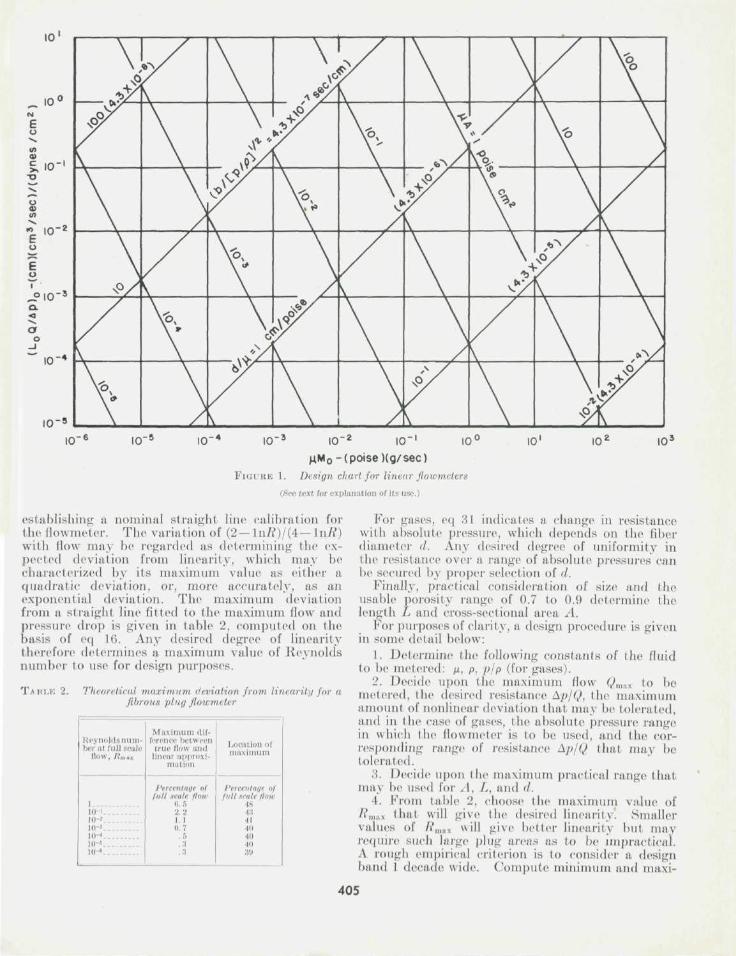
Equation 30 may be plotted as a generalized chartapplicable to all fluids, or, by choice of fluid param-eters, as a design chart suitable fora specific fluid.I t is presented in generalized form in figure' 1 as alogarithmic plot of (Q/Ap)L0 against- 11M „ forconstant values of ^.1 and d/n respectively. The useof figure 1 or 6Q 30 leads to values of A, L, and </ fora,porous plug tha t nominally will have the desiredresistance Ap/Q. The besi choice of these parametersdepends upon the deviat ions from constant resistancet h a t m a y be tolerated.
As the permeability theory developed has onlynominal cer ta in ty , it is not to be expected that a,desired resistance will be experimentally obtainedwith any great accuracy, so that in general, a moder-ate amount of resistance adjustment will be foundnecessary. (Illustratively, this may be accom-plished by variation of the.weight ol glass wool used.)Therefore Little distinction need be made as to thenominal design value of ApjQ. T h e value (Ap/Q)0
may thus be regarded as the resistance at full scale,
404
IO~9
10' 10- 5 10- 4 10~3 IO~2 10"'
u.M0- (poise Kg/ sec)FIGURE 1. Design chart for linear flowmeters
(See text for explanation of its use.)
10' 10' 10'
establishing a nominal straight line calibration forthe flowmeter. The variation of (2— In/?)/(4— IILR)with flow may be regarded as determining the ex-pected deviation from linearity, which may becharacterized by its maximum value as either aquadratic deviation, or, more accurately, as anexponential deviation. The maximum deviationfrom a straight line fitted to the maximum flow andpressure drop is given in table 2, computed on thebasis of eq Hi. Any desired degree of linearitytherefore determines a maximum value of Reynoldsnumber to use for design purposes.
TABLE 2. Theoretical maximum deviation from linearity for afibrous pi no flowmeter
Reynoldsnum-ber at lull scale
How, Rm H
110-'1<H10-'in 'io-«10 •
Maximum dif-ference between
true Mow andlinear approxi-
mation
Percentage o)lull scale iiini
6 . -ri
I . I
(I. 7
. : ;
.3
Location ofmaximum
Percentage o)full 8CaU !l<nr
4843•1140404039
For gases, eq 31 indicates a change in resistancewith absolute pressure, which depends on the fiberdiameter d. Any desired degree of uniformity inthe resistance over a range of absolute pressures canbe secured by proper selection of d.
Finally, practical consideration of size and theusable porosity range of 0.7 to 0.9 determine thelength L and cross-sectional area A.
For purposes of clarity, a design procedure is givenin some detail below:
1. Determine the following constants of the fluidto be metered: M, p, p/p (for gases).
2. Decide upon the maximum How Qmax to bemetered, the desired resistance Ap/Q, the maximumamount of nonlinear deviation that may be tolerated,and in the case of gases, the absolute pressure rangein which the flowmeter is to be used, and the cor-responding range of resistance Ap/Q thai may betolerated.
3. Decide upon the maximum practical range thatmay be used for A, L, and </.
4. F rom table 2, choose the maximum value of/ i \n a x that will give the desired linearity. Smallervalues of Rmft, will give belter linearity but mayrequire such large plug areas as to be impractical.A rough empirical criterion is to consider a designband 1 decade wide. Compute minimum and maxi-
405
mum values of Mo (eq 29) assuming minimum andmaximum values for both Rmax and e. The range of* may be taken as 0.7 to 0.9. Compute the cor-responding values for fx Mo and mark out the verticalband corresponding to these limits in figure 1.
5. For the maximum and minimum limits assumedfor both L and e, compute the corresponding limitsfor Lo (eq 28). Compute the corresponding valuesof QL0/Ap and mark out the horizontal band cor-responding to these limits in figure 1. Steps (4) and(5) result in a design rectangle on figure 1 withinwhich a solution is possible.
6. Further limit this design rectangle by excludingregions of figure 1 representing greater and lesserarea A (really /JLA) than desired.
7. For gas flow, compute the maximum tolerablevalue of the coefficient of the Knudsen term b andthe corresponding minimum value of fiber diameterd. Exclude regions of figure 1 representing smallervalues of d (really d/fi). One may then choosedesign parameters corresponding to any point inthe design region that has not been excluded.
8. When the flowmeter is built and tested, adjust-ment of the resistivity can then be made by theprincipal technique^of changing the weight of glasswool used.
Financial support for this investigation was pro-vided by the Office of Naval Research under a proj-ect on Basic Instrumentation of Scientific Research.Grateful acknowledgement is also due W. A. Wild-hack, at whose suggestion and under whose super-vision the development of the glass wool flowmeterwas carried on.
V. References
[1] National Bureau of Standards Report to the Bureau ofAeronautics, Navy Department, Washington, D. C ,entitled, Linear pressure drop flowmeters for oxygenregulator test stands, reference 6.2/6211-2885 (Sept. 25,1947).
[2] P. C. Carman, Trans. Institution Chem. Engrs. 15, 151(1937); 16, 168 (1938).
[3] P. C. Carman, J. Soc. Chem. Ind. 57, 225 (1938); 58,1 (1939).
[4] E. Wiggin, W. Campbell, O. Maass, Can. J. Research 17,318 (1939).
[5] J. Fowler and K. Hertel, J. App. Phys. 12, 503 (1941).[6] R. Sullivan, J. App. Phys. 12, 503 (1941); 13, 725 (1942).[7] O. Emersleben, Physik. Z. 26, 601 (1925).[8] R. Tolman, Statistical mechanics with applications to
physics and chemistry (Chemical Catalogue Co., NewYork, N. Y., 1927).
WASHINGTON, April 6, 1950.
Journal of Research of the National Bureau of Standards Vol. 45, No. 5, November 1950 Research Paper 2151
Density, Refractive Index, Boiling Point, and VaporPressure of Eight Monoolefin (1-Alkene), Six Pentadiene,
and Two Cyclomonoolefin Hydrocarbons1
By Alphonse F. Forziati,2 David L. Camin,! and Frederick D. Rossini3
Density (at 20°, 25°, and 30° C), refractive index (at seven wavelengths at 20°, 25°,and 30° C), vapor pressure, and boiling point (from 48 to 778 mm Eg) of 16 highly purifiedsamples of hydrocarbons of the AIM NBS series were measured for S monoolefin (1-alkene),(> pentadiene, and 2 cyclomonoolefin hydrocarbons.
The data on refractive index were adjusted by means of modified Cauchy and Hart-mann equations, and values of the constants are given for each compound.
The data on vapor pressure were adjusted by means of the method of least squaresand the three-constant Antoine equation. The values of the constants are given for eachcompound.
Values were calculated for the specfic dispersions, (nF—nc)ld and {nK — nn)l<i.
As a cooperative investigation of the Nat ionalBureau of S t a n d a r d s , the I1. S. Office of RubberReserve, and the American Petroleum [nstituteResearch Project (>, measurements of density, re-fractive index, vapor pressure, and boiling point,were made on highly purified samples of ei<j:htnionoolclin (1-alkene), six pentadiene, and twocyclomonoolelin hydrocarbons of the API NBSseries.
The compounds measured were made available'This investigation was performed at the National Bureau "f Standards :is
part of the work of the American Petroleum [nstitute Research Project 6 on the"Analysis, purification, and properties <>i hydrocarbons."
Formerly Research Associate on the American Petroleum [nstitute ResearchProject <'..
1 Present address: Carnegie [nstitute of Technology, Pittsburgh 13, Pa.
through (lie American Petroleum Ins t i tu te ResearchProject 11 on the "Collection, calculat ion, andcompilat ion of data on the properties of hydrocar -bons . " T h e samples were purified by the AmericanPetroleum Ins t i tu te Research Project 6 on the"Analysis , purification, and properties of hydro-carbons," Iron) material supplied by the followinglaboratories:
L-Pentene, by the Phillips Petroleum Co., Bartles-ville, Okla.
l-IIexene, l -heptene, l-noneiie, L-undecene, and1,4-penfadiene, by the American Petroleum Ins t i tu teResearch Project 45, at the Ohio S ta le University,(Jolumbus, Ohio.
406