performancestudyofmodifiedsavoniuswaterturbinewith...
TRANSCRIPT
Hindawi Publishing CorporationInternational Journal of Rotating MachineryVolume 2012, Article ID 679247, 12 pagesdoi:10.1155/2012/679247
Research Article
Performance Study of Modified Savonius Water Turbine withTwo Deflector Plates
Golecha Kailash, T. I. Eldho, and S. V. Prabhu
Department of Mechanical Engineering, Indian Institute of Technology, Powai, Mumbai 400 076, India
Correspondence should be addressed to S. V. Prabhu, [email protected]
Received 12 November 2011; Accepted 13 January 2012
Academic Editor: Tariq Iqbal
Copyright © 2012 Golecha Kailash et al. This is an open access article distributed under the Creative Commons AttributionLicense, which permits unrestricted use, distribution, and reproduction in any medium, provided the original work is properlycited.
Savonius rotor is a vertical axis rotor with simple in design and easy to fabricate at lower cost. The rotation of the rotor is due tothe drag difference between the advancing blade and returning blade. Net driving force can be increased by reducing the reverseforce on the returning blade or increasing the positive force on the advancing blade. Former can be realized by providing a flowobstacle to the returning blade and latter can be realized by concentrating the flow towards the advancing blade. The objectiveof the present work is to identify the optimal position of the deflector plate (on advancing blade side) placed upstream to theflow which would result in increase in power generated by the rotor. Tests are conducted to identify the optimum position of thedeflector plate on the advancing blade side in the presence of a deflector plate on the returning blade side at its optimum position.Results suggest that two deflector plates placed at their optimal positions upstream to the flow increase the coefficient of power to0.35. This is significantly higher than the coefficient of power of 0.14 observed for the rotor without deflector plates.
1. Introduction
Hydropower from the river is one of the best renewablesources. Hydropower source is predictable compared towind or solar energy. Water current turbines are zero headturbines. They generate electricity using the kinetic energyof natural water resources using different types of rotors.Usually, these rotors are fixed to a structure on the riversideor on floating pontoons. Hydrokinetic turbine electricitygeneration is mainly aimed for rural use at sites remote fromexisting electricity grids. It is a useful tool for improving thequality of life of people in these locations and for improvinglocal economies. Different designs of water current turbineare available for the extraction of energy from the river wateror canals. Based on the alignment of the rotor axis withrespect to water flow, two generic classes exist. They are hor-izontal axis turbine (axial turbines) and vertical axis turbine(cross-flow turbines). Commonly used vertical axis turbinesare Savonius turbine, helical turbine, Darrieus turbine, andH-shaped Darrieus turbine.
Research on the water current turbines is going on world-wide. Literature suggests that water turbines are gaining
popularity [1–3]. Different kinds of water turbines are beinginstalled and tested. In the coast of Korea, GCK TechnologyLimited (USA) installed a Gorlov helical water turbine witha diameter of 1 m and height of 2.5 m [4]. Gorlov verticalaxis water turbine has the blades of helical structure. It wasproposed by Gorlov [5] to convert kinetic energy of the flow-ing water into electrical or mechanical energy. The advantageof this turbine is that it reduces the relative diameter of therotor while simultaneously increasing the length of the blade.Verdant Power Limited (USA) also installed a three-bladedaxial water turbine to extract the water energy from free flowin the east river New York [4]. Alternative Hydro SolutionsLtd. in Ontario has developed vertical axis turbines to extractthe water energy from river [6]. New Energy CorporationInc., with support from Natural Resources Canada and theCANMET Energy Technology Centre, is developing a seriesof turbine/generator sets that produce between 5 kW and25 kW of power and can be used in rivers, irrigation canals,industrial outflows, and tidal estuaries. The turbines are ofvertical axis water turbines [7].
Majority of the turbines installed in Ireland and devel-oped to extract the tidal and marine current energy are
2 International Journal of Rotating Machinery
170 mm
330 mm
(a)
269.5 mm
730 mm
245 mm
(b)
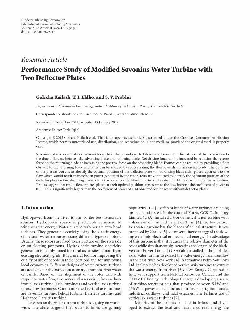
Figure 1: (a) Side view of the experimental setup and channel. (b) Top view of the experimental set-up channel.
7
1
2
3
4
5
6
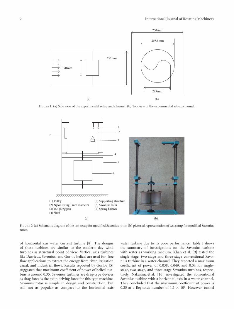
(1) Pulley(2) Nylon string 1 mm diameter(3) Weighing pan(4) Shaft
(5) Supporting structure(6) Savonius rotor(7) Spring balance
(a) (b)
Figure 2: (a) Schematic diagram of the test setup for modified Savonius rotor, (b) pictorial representation of test setup for modified Savoniusrotor.
of horizontal axis water current turbine [8]. The designsof these turbines are similar to the modern day windturbines as structural point of view. Vertical axis turbineslike Darrieus, Savonius, and Gorlov helical are used for freeflow applications to extract the energy from river, irrigationcanal, and industrial flows. Results reported by Gorlov [5]suggested that maximum coefficient of power of helical tur-bine is around 0.35. Savonius turbines are drag-type devicesas drag force is the main driving force for this type machine.Savonius rotor is simple in design and construction, butstill not as popular as compare to the horizontal axis
water turbine due to its poor performance. Table 1 showsthe summary of investigations on the Savonius turbinewith water as working medium. Khan et al. [9] tested thesingle-stage, two-stage and three-stage conventional Savo-nius turbine in a water channel. They reported a maximumcoefficient of power of 0.038, 0.049, and 0.04 for single-stage, two-stage, and three-stage Savonius turbines, respec-tively. Nakajima et al. [10] investigated the conventionalSavonius turbine with a horizontal axis in a water channel.They concluded that the maximum coefficient of power is0.25 at a Reynolds number of 1.1 × 10⁵. However, tunnel
International Journal of Rotating Machinery 3
Table 1: Summary of experimental investigation carried out by researchers on Savonius turbines with water as working medium.
AuthorTurbine
aspect ratio(H/D)
Reynoldsnumber× 105
Free streamvelocity(m/s)
Water tunneldimensions
(m ×m)
Orientationof the axis
Turbines testedParametersmeasured
Results
Khanet al. [9]
1.820.98,1.52,1.96
1 5× 3 Vertical
Single-stage,two-stage, three-stageconventional Savoniusturbines with anoverlap ratio of 0.207
Cp, Ct
Cpmax of 0.038, 0.049, and0.04 for single-, two-, andthree-stage Savoniusturbines
Nakajimaet al. [10]
1.48 1.1 0.8 0.6× 0.5 HorizontalSingle-stageconventional Savoniusturbine
Cp, flowvisualisation
Cpmax of 0.25 forsingle-stage Savoniusturbine
Nakajimaet al. [11]
1.2, 2.4 1.1 0.8 0.6× 0.5 Horizontal
Single-stage andtwo-stage conventionalSavonius turbine withan overlap ratio of 0.36
Cp, flowvisualisation
Cpmax of 0.275 fortwo-stage with 90◦ phaseshift compared to 0.25 forsingle-stage turbine andflow visualisation gives thetorque generationmechanism
Golechaet al. [12]
0.70 1.32 0.45 0.73× 0.33 Vertical
Single-stage, two-stageand three-stagemodified Savoniusturbine with andwithout deflector plate
Cp, Ct
50% improvement in theCpmax for single-stagemodified Savonius withdeflector plate at optimalposition
D
q p
pq
ψψ
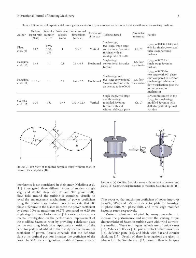
Figure 3: Top view of modified Savonius rotor without shaft inbetween the end plates [18].
interference is not considered in their study. Nakajima et al.[11] investigated three different types of models (singlestage and double stage with 0◦ and 90◦ phase shift).Flow field around the turbine is examined visually toreveal the enhancement mechanisms of power coefficientusing the double stage turbine. Results indicate that 90◦
phase difference in the blades improve the power coefficientby about 10% at maximum (0.275 compared to 0.25 forsingle stage turbine). Golecha et al. [12] carried out an exper-imental investigation on the performance improvement ofthe modified Savonius rotor by providing a deflector plateon the returning blade side. Appropriate position of thedeflector plate is identified in their study for the maximumcoefficient of power. Results conclude that the deflectorplate at its optimal position increases the coefficient of thepower by 50% for a single-stage modified Savonius rotor.
U θ
2p
qψ
D
H
(a) (b)
Figure 4: (a) Modified Savonius rotor without shaft in between endplates. (b) Geometrical parameters of modified Savonius rotor [18].
They reported that maximum coefficient of power improvesby 42%, 31%, and 17% with deflector plate for two-stage0◦ phase shift, 90◦ phase shift, and three-stage modifiedSavonius rotor, respectively.
Various techniques adopted by many researchers toincrease the performance and improve the starting torquecharacteristics of Savonius turbine were with wind as work-ing medium. These techniques include use of guide vanes[13], V-block deflector [14], partially blocked Savonius rotor[15], deflector plate [16], and blade with flat and circularshielding [17]. Details of these investigations are given intabular form by Golecha et al. [12]. Some of these techniques
4 International Journal of Rotating Machinery
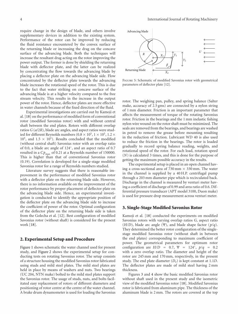
require change in the design of blade, and others involvesupplementary devices in addition to the existing system.Performance of the rotor can be improved by reducingthe fluid resistance encountered by the convex surface ofthe returning blade or increasing the drag on the concavesurface of the advancing blade. Both the techniques willincrease the resultant drag acting on the rotor improving thepower output. The former is done by shielding the returningblade with deflector plate, and the latter can be realizedby concentrating the flow towards the advancing blade byplacing a deflector plate on the advancing blade side. Flowconcentrated by the deflector plate towards the advancingblade increases the rotational speed of the rotor. This is dueto the fact that water striking on concave surface of theadvancing blade is at a higher velocity compared to the freestream velocity. This results in the increase in the outputpower of the rotor. Hence, deflector plates are more effectivein water channels because of the fixed direction of the fluid.
Experimental investigations are carried out by Kamoji etal. [18] on the performance of modified form of conventionalrotor (modified Savonius rotor) with and without centralshaft between the end plates. Rotors with different overlapratios G (a/2R), blade arc angles, and aspect ratios were stud-ied for different Reynolds numbers (0.8 × 10⁵, 1× 10⁵, 1.2×10⁵, and 1.5 × 10⁵). Results concluded that the modified(without central shaft) Savonius rotor with an overlap ratioof 0.0, a blade arc angle of 124◦, and an aspect ratio of 0.7resulted in a Cpmax of 0.21 at a Reynolds number of 150000.This is higher than that of conventional Savonius rotor(0.19). Correlation is developed for a single-stage modifiedSavonius rotor for a range of Reynolds numbers studied.
Literature survey suggests that there is reasonable im-provement in the performance of modified Savonius rotorwith a deflector plate on the returning blade side. However,there is no information available on the improvement of therotor performance by proper placement of deflector plate onthe advancing blade side. Hence, an experimental investi-gation is conducted to identify the appropriate position ofthe deflector plate on the advancing blade side to increasethe coefficient of power of the rotor. Optimal configurationof the deflector plate on the returning blade side is takenfrom the Golecha et al. [12]. Best configuration of modifiedSavonius rotor (without shaft) is considered for the presentwork [18].
2. Experimental Setup and Procedure
Figure 1 shows schematic the water channel used for presentstudy, and Figure 2 shows the experimental setup for con-ducting tests on rotating Savonius rotor. The setup consistsof a structure housing the modified Savonius rotor fabricatedusing studs and mild steel plates. The mild steel plates areheld in place by means of washers and nuts. Two bearings(UC 204, NTN make) bolted to the mild steel plates supportthe Savonius rotor. The usage of studs, nuts, and bolts facil-itated easy replacement of rotors of different diameters andpositioning of rotor centre at the centre of the water channel.A brake drum dynamometer is used for loading the Savonius
Advancing blade
Returning blade
RU
X1
X2
Y2
Y1
β
Figure 5: Schematic of modified Savonius rotor with geometricalparameters of deflector plate [12].
rotor. The weighing pan, pulley, and spring balance (Saltermake, accuracy of 2.5 gms) are connected by a nylon stringof 1 mm diameter. Friction is an important parameter thataffects the measurement of torque of the rotating Savoniusrotor. Friction in the bearings and the 1 mm inelastic fishingnylon wire wound on the rotor shaft must be minimized. Theseals are removed from the bearings, and bearings are washedin petrol to remove the grease before mounting resultingin the reduction of friction. Lubricant WD 40 is also usedto reduce the friction in the bearings. The rotor is loadedgradually to record spring balance reading, weights, androtational speed of the rotor. For each load, rotation speed(N) is calculated 3 times, and this is done for the purpose ofgetting the maximum possible accuracy in the results.
The experimental setup is placed in an open channel hav-ing a cross-sectional area of 730 mm × 330 mm. The waterin the channel is supplied by a 40 H.P. centrifugal pumpthrough a 203 mm diameter pipe which is recirculated back.Discharge in the channel is measured by venturi meter hav-ing a coefficient of discharge of 0.99 and area ratio of 0.6. Dif-ferential pressure transducer (APT model 3100, Duon make)is used for pressure drop measurement across venturi meter.
3. Single-Stage Modified Savonius Rotor
Kamoji et al. [18] conducted the experiments on modifiedSavonius rotors with varying overlap ratios G, aspect ratio(H/D), blade arc angle (Ψ), and blade shape factor (p/q).They determined the better rotor configuration of the single-stage modified Savonius rotor (without shaft in betweenthe end plates) corresponding to maximum coefficient ofpower. The geometrical parameters for optimum rotorconfiguration are H/D = 0.7, Ψ = 124◦, p/q = 0.2with a zero overlap ratio. The diameter and height of therotor are 245 mm and 170 mm, respectively, in the presentstudy. The end plate diameter (Do) is kept constant at 1.1D.The deflector plates are made of mild steel having 2 mmthickness.
Figures 3 and 4 show the basic modified Savonius rotorwithout shaft used in the present study and the isometricview of the modified Savonius rotor [18]. Modified Savoniusrotor is fabricated from aluminum pipe. The thickness of thealuminum blade is 2 mm. The rotors are covered at the top
International Journal of Rotating Machinery 5
32
654
7 8
1
Modified Savonius without deflector
Cpmax Cpmax Cpmax
Cpmax Cpmax Cpmax
Cpmax Cpmax Cpmax
= 0.14 = 0.21 = 0.16
= 0.15 = 0.15 = 0.14
= 0.15 = 0.11 = 0.17
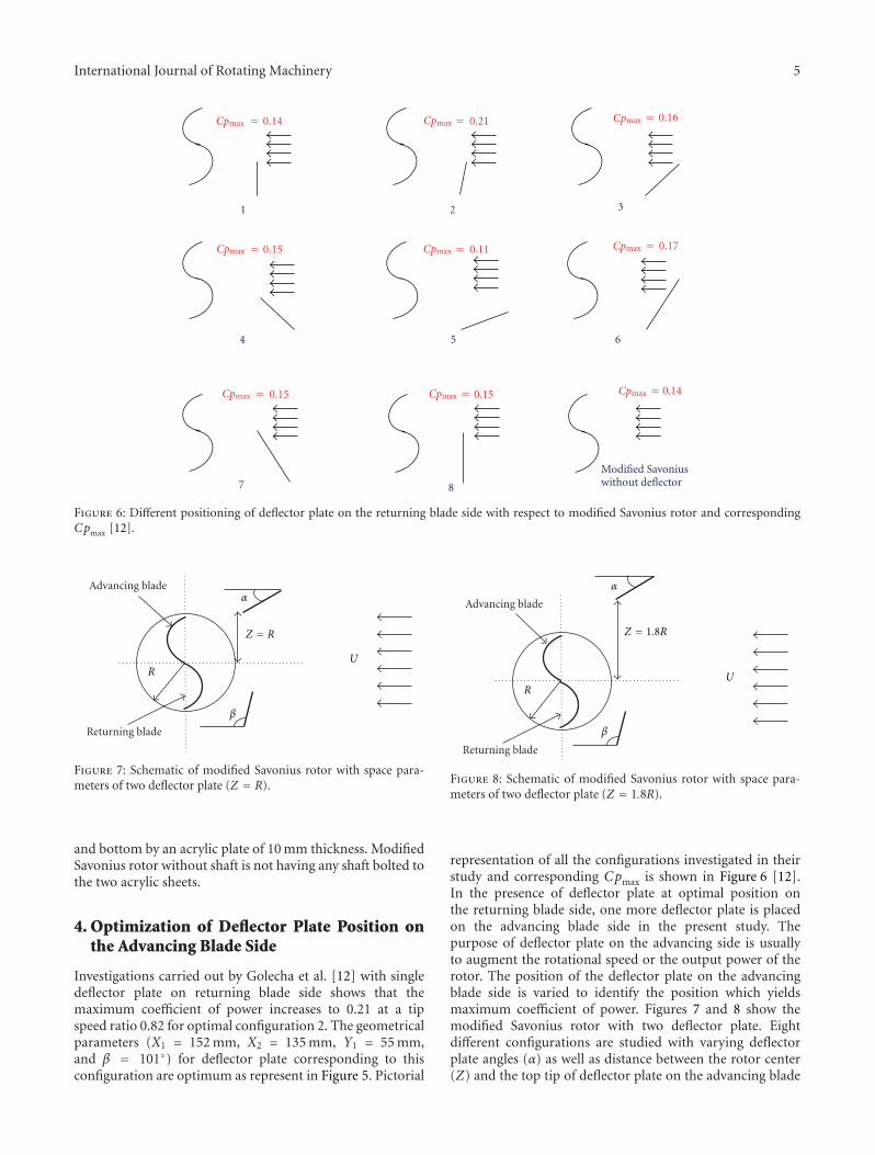
Figure 6: Different positioning of deflector plate on the returning blade side with respect to modified Savonius rotor and correspondingCpmax [12].
Advancing blade
Returning blade
RU
Z = R
α
β
Figure 7: Schematic of modified Savonius rotor with space para-meters of two deflector plate (Z = R).
and bottom by an acrylic plate of 10 mm thickness. ModifiedSavonius rotor without shaft is not having any shaft bolted tothe two acrylic sheets.
4. Optimization of Deflector Plate Position onthe Advancing Blade Side
Investigations carried out by Golecha et al. [12] with singledeflector plate on returning blade side shows that themaximum coefficient of power increases to 0.21 at a tipspeed ratio 0.82 for optimal configuration 2. The geometricalparameters (X1 = 152 mm, X2 = 135 mm, Y1 = 55 mm,and β = 101◦) for deflector plate corresponding to thisconfiguration are optimum as represent in Figure 5. Pictorial
Advancing blade
Returning blade
RU
α
β
Z = 1.8R
Figure 8: Schematic of modified Savonius rotor with space para-meters of two deflector plate (Z = 1.8R).
representation of all the configurations investigated in theirstudy and corresponding Cpmax is shown in Figure 6 [12].In the presence of deflector plate at optimal position onthe returning blade side, one more deflector plate is placedon the advancing blade side in the present study. Thepurpose of deflector plate on the advancing side is usuallyto augment the rotational speed or the output power of therotor. The position of the deflector plate on the advancingblade side is varied to identify the position which yieldsmaximum coefficient of power. Figures 7 and 8 show themodified Savonius rotor with two deflector plate. Eightdifferent configurations are studied with varying deflectorplate angles (α) as well as distance between the rotor center(Z) and the top tip of deflector plate on the advancing blade
6 International Journal of Rotating Machinery
With single deflector plate
32
654
7 8
1
Figure 9: Different arrangements of the two deflector plates studied in the present study with the deflector plate on the returning blade sideis at its optimum position.
Tip speed ratio (TSR)
0 0.2 0.4 0.6 0.8 1 1.2 1.40
0.05
0.1
0.15
0.2
0.25
Coe
ffici
ent
of p
ower
(Cp
)
(a)
Modified Savonius (without deflector)
Tip speed ratio (TSR)
0 0.2 0.4 0.6 0.8 1 1.2 1.40
0.05
0.1
0.15
0.2
0.25
0.3
0.35
Coe
ffici
ent
of p
ower
(Cp)
(b)
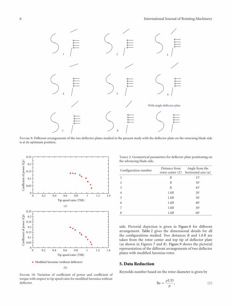
Figure 10: Variation of coefficient of power and coefficient oftorque with respect to tip speed ratio for modified Savonius withoutdeflector.
Table 2: Geometrical parameters for deflector plate positioning onthe advancing blade side.
Configuration numberDistance from
rotor center (Z)Angle from the
horizontal axis (α)
1 R 15◦
2 R 30◦
3 R 45◦
4 1.8R 20◦
5 1.8R 30◦
6 1.8R 40◦
7 1.8R 50◦
8 1.8R 60◦
side. Pictorial depiction is given in Figure 8 for differentarrangement. Table 2 gives the dimensional details for allthe configurations studied. Two distances R and 1.8R aretaken from the rotor center and top tip of deflector plate(as shown in Figures 7 and 8). Figure 9 shows the pictorialrepresentation of the different arrangements of two deflectorplates with modified Savonius rotor.
5. Data Reduction
Reynolds number based on the rotor diameter is given by
Re = ρUD
μ, (1)
International Journal of Rotating Machinery 7
Two-way 1–15Without deflector
0
0.05
0.1
0.15
0.2
0.25
0.3
0.35C
oeffi
cien
t of
pow
er (Cp)
0 0.2 0.4 0.6 0.8 1 1.2 1.4 1.6
Tip speed ratio (TSR)
•
(a)
Without deflector
0
0.05
0.1
0.15
0.2
0.25
0.3
0.35
Coe
ffici
ent
of p
ower
(Cp)
0 0.2 0.4 0.6 0.8 1 1.2 1.4 1.6
Tip speed ratio (TSR)
•Two-way 2–30
(b)
Without deflector
0
0.05
0.1
0.15
0.2
0.25
0.3
0.35
Coe
ffici
ent
of p
ower
(Cp)
0 0.2 0.4 0.6 0.8 1 1.2 1.4 1.6
Tip speed ratio (TSR)
•Two-way 3–45
(c)
Without deflector
0
0.05
0.1
0.15
0.2
0.25
0.3
0.35C
oeffi
cien
t of
pow
er (Cp)
0 0.2 0.4 0.6 0.8 1 1.2 1.4 1.6
Tip speed ratio (TSR)
•Two-way 4–20
(d)
Without deflector
0
0.05
0.1
0.15
0.2
0.25
0.3
0.35
Coe
ffici
ent
of p
ower
(Cp)
0 0.2 0.4 0.6 0.8 1 1.2 1.4 1.6
Tip speed ratio (TSR)
•Two-way 5–30
(e)
Without deflector
0
0.05
0.1
0.15
0.2
0.25
0.3
0.35
Coe
ffici
ent
of p
ower
(Cp)
0 0.2 0.4 0.6 0.8 1 1.2 1.4 1.6
Tip speed ratio (TSR)
•Two-way 6–40
(f)
Figure 11: Continued.
8 International Journal of Rotating Machinery
Without deflector
0
0.05
0.1
0.15
0.2
0.25
0.3
0.35C
oeffi
cien
t of
pow
er (Cp)
0 0.2 0.4 0.6 0.8 1 1.2 1.4 1.6
Tip speed ratio (TSR)
•Two-way 7–50
(g)
Without deflector
0
0.05
0.1
0.15
0.2
0.25
0.3
0.35
Coe
ffici
ent
of p
ower
(Cp)
0 0.2 0.4 0.6 0.8 1 1.2 1.4 1.6
Tip speed ratio (TSR)
•Two-way 8–60
(h)
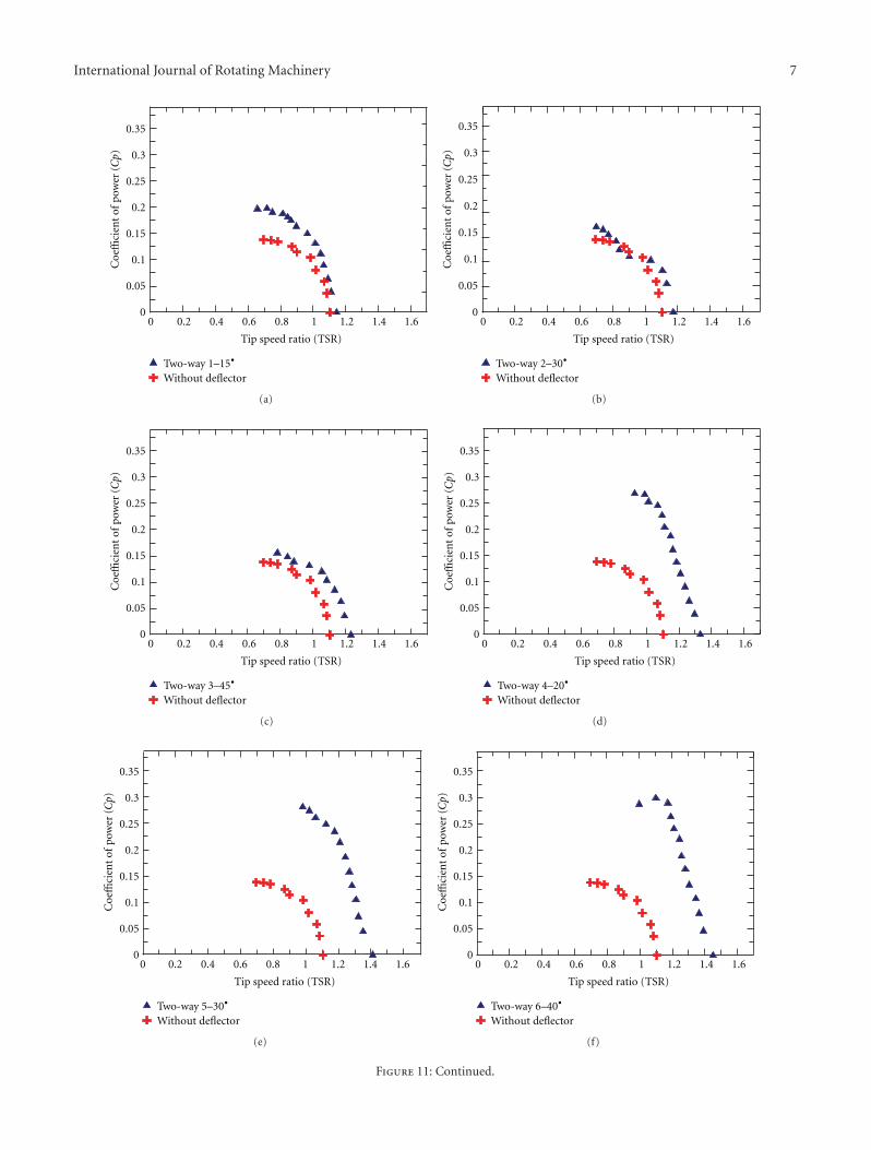
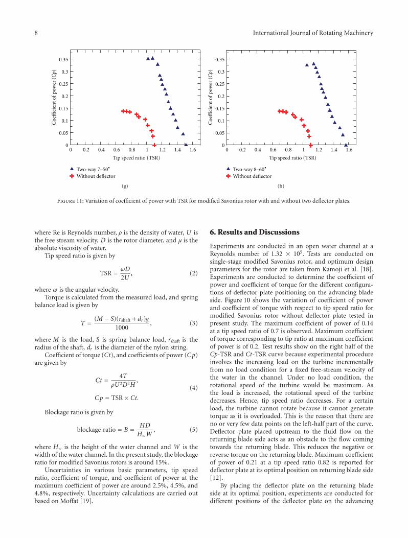
Figure 11: Variation of coefficient of power with TSR for modified Savonius rotor with and without two deflector plates.
where Re is Reynolds number, ρ is the density of water, U isthe free stream velocity, D is the rotor diameter, and μ is theabsolute viscosity of water.
Tip speed ratio is given by
TSR = ωD
2U, (2)
where ω is the angular velocity.Torque is calculated from the measured load, and spring
balance load is given by
T = (M − S)(rshaft + dr)g1000
, (3)
where M is the load, S is spring balance load, rshaft is theradius of the shaft, dr is the diameter of the nylon string.
Coefficient of torque (Ct), and coefficients of power (Cp)are given by
Ct = 4TρU2D2H
,
Cp = TSR× Ct.(4)
Blockage ratio is given by
blockage ratio = B = HD
HwW, (5)
where Hw is the height of the water channel and W is thewidth of the water channel. In the present study, the blockageratio for modified Savonius rotors is around 15%.
Uncertainties in various basic parameters, tip speedratio, coefficient of torque, and coefficient of power at themaximum coefficient of power are around 2.5%, 4.5%, and4.8%, respectively. Uncertainty calculations are carried outbased on Moffat [19].
6. Results and Discussions
Experiments are conducted in an open water channel at aReynolds number of 1.32 × 10⁵. Tests are conducted onsingle-stage modified Savonius rotor, and optimum designparameters for the rotor are taken from Kamoji et al. [18].Experiments are conducted to determine the coefficient ofpower and coefficient of torque for the different configura-tions of deflector plate positioning on the advancing bladeside. Figure 10 shows the variation of coefficient of powerand coefficient of torque with respect to tip speed ratio formodified Savonius rotor without deflector plate tested inpresent study. The maximum coefficient of power of 0.14at a tip speed ratio of 0.7 is observed. Maximum coefficientof torque corresponding to tip ratio at maximum coefficientof power is of 0.2. Test results show on the right half of theCp-TSR and Ct-TSR curve because experimental procedureinvolves the increasing load on the turbine incrementallyfrom no load condition for a fixed free-stream velocity ofthe water in the channel. Under no load condition, therotational speed of the turbine would be maximum. Asthe load is increased, the rotational speed of the turbinedecreases. Hence, tip speed ratio decreases. For a certainload, the turbine cannot rotate because it cannot generatetorque as it is overloaded. This is the reason that there areno or very few data points on the left-half part of the curve.Deflector plate placed upstream to the fluid flow on thereturning blade side acts as an obstacle to the flow comingtowards the returning blade. This reduces the negative orreverse torque on the returning blade. Maximum coefficientof power of 0.21 at a tip speed ratio 0.82 is reported fordeflector plate at its optimal position on returning blade side[12].
By placing the deflector plate on the returning bladeside at its optimal position, experiments are conducted fordifferent positions of the deflector plate on the advancing
International Journal of Rotating Machinery 9
0
0.05
0.1
0.15
0.2
0.25
0.3
0.35C
oeffi
cien
t of
torq
ue
(Ct)
Without deflector
0 0.2 0.4 0.6 0.8 1 1.2 1.4 1.6
Tip speed ratio (TSR)
•Two-way 1–15
(a)
0
0.05
0.1
0.15
0.2
0.25
0.3
0.35
Coe
ffici
ent
of to
rqu
e (Ct)
Without deflector
0 0.2 0.4 0.6 0.8 1 1.2 1.4 1.6
Tip speed ratio (TSR)
•Two-way 2–30
(b)
0
0.05
0.1
0.15
0.2
0.25
0.3
0.35
Coe
ffici
ent
of to
rqu
e (Ct)
Without deflector
0 0.2 0.4 0.6 0.8 1 1.2 1.4 1.6
Tip speed ratio (TSR)
•Two-way 3–45
(c)
0
0.05
0.1
0.15
0.2
0.25
0.3
0.35C
oeffi
cien
t of
torq
ue
(Ct)
Without deflector
0 0.2 0.4 0.6 0.8 1 1.2 1.4 1.6
Tip speed ratio (TSR)
•Two-way 4–20
(d)
0
0.05
0.1
0.15
0.2
0.25
0.3
0.35
Coe
ffici
ent
of to
rqu
e (Ct)
Without deflector
0 0.2 0.4 0.6 0.8 1 1.2 1.4 1.6
Tip speed ratio (TSR)
•Two-way 5–30
(e)
0
0.05
0.1
0.15
0.2
0.25
0.3
0.35
Coe
ffici
ent
of to
rqu
e (Ct)
Without deflector
0 0.2 0.4 0.6 0.8 1 1.2 1.4 1.6
Tip speed ratio (TSR)
•Two-way 6–40
(f)
Figure 12: Continued.
10 International Journal of Rotating Machinery
0
0.05
0.1
0.15
0.2
0.25
0.3
0.35C
oeffi
cien
t of
torq
ue
(Ct)
Two-way 7–50Without deflector
0 0.2 0.4 0.6 0.8 1 1.2 1.4 1.6
Tip speed ratio (TSR)
•
(g)
0
0.05
0.1
0.15
0.2
0.25
0.3
0.35
Coe
ffici
ent
of to
rqu
e (Ct)
Without deflector
0 0.2 0.4 0.6 0.8 1 1.2 1.4 1.6
Tip speed ratio (TSR)
•Two-way 8–60
(h)
Figure 12: Variation of coefficient of torque with TSR for modified Savonius rotor with and without two deflector plate.
Table 3: Maximum coefficient of power and the corresponding tipspeed ratio and coefficient of torque for the configuration studiedon the two deflector plates.
Configurationnumber
Maximumcoefficient ofpower Cpmax
Tip speed ratiocorresponding
to Cpmax
Maximumcoefficient of
torque at Cpmax
1 0.20 0.72 0.26
2 0.16 0.70 0.23
3 0.15 0.78 0.20
4 0.27 0.93 0.29
5 0.28 0.98 0.29
6 0.30 1.01 0.27
7 0.35 1.10 0.32
8 0.33 1.14 0.29
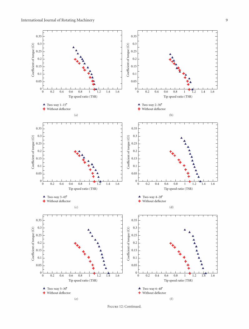
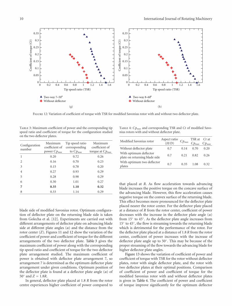
blade side of modified Savonius rotor. Optimum configura-tion of deflector plate on the returning blade side is takenfrom Golecha et al. [12]. Experiments are carried out withdifferent arrangements of deflector plate on advancing bladeside at different plate angles (α) and the distance from therotor center (Z). Figures 11 and 12 show the variation of thecoefficient of power and coefficient of torque for the differentarrangements of the two deflector plate. Table 3 gives themaximum coefficient of power along with the correspondingtip speed ratio and coefficient of torque for the two deflectorplate arrangement studied. The maximum coefficient ofpower is obtained with deflector plate arrangement 7, soarrangement 7 is determined as the optimum deflector platearrangement under given conditions. Optimum position ofthe deflector plate is found at a deflector plate angle (α) of50◦ and Z = 1.8R.
In general, deflector plate placed at 1.8 R from the rotorcentre experiences higher coefficient of power compared to
Table 4: Cpmax and corresponding TSR and Ct of modified Savo-nius rotors with and without deflector plate.
Modified Savonius rotorAspect ratio
(H/D)Cpmax
TSR atCpmax
Ct atCpmax
Without deflector plate 0.7 0.14 0.70 0.20
With optimum deflectorplate on returning blade side
0.7 0.21 0.82 0.26
With optimum two deflectorplates
0.7 0.35 1.08 0.32
that placed at R. As flow acceleration towards advancingblade increases the positive torque on the concave surface ofthe advancing blade. However, this flow acceleration causesnegative torque on the convex surface of the returning blade.This effect becomes more pronounced for the deflector plateplaced nearer the rotor center. For the deflector plate placedat a distance of R from the rotor center, coefficient of powerdecreases with the increase in the deflector plate angle (α)from 15◦ to 45◦. As the deflector plate angle increases from15◦ to 45◦, the flow is streaming towards the returning bladewhich is detrimental for the performance of the rotor. Forthe deflector plate placed at a distance of 1.8R from the rotorcenter, coefficient of power increases with the increase ofdeflector plate angle up to 50◦. This may be because of theproper streaming of the flow towards the advancing blade forhigher deflector plate angles.
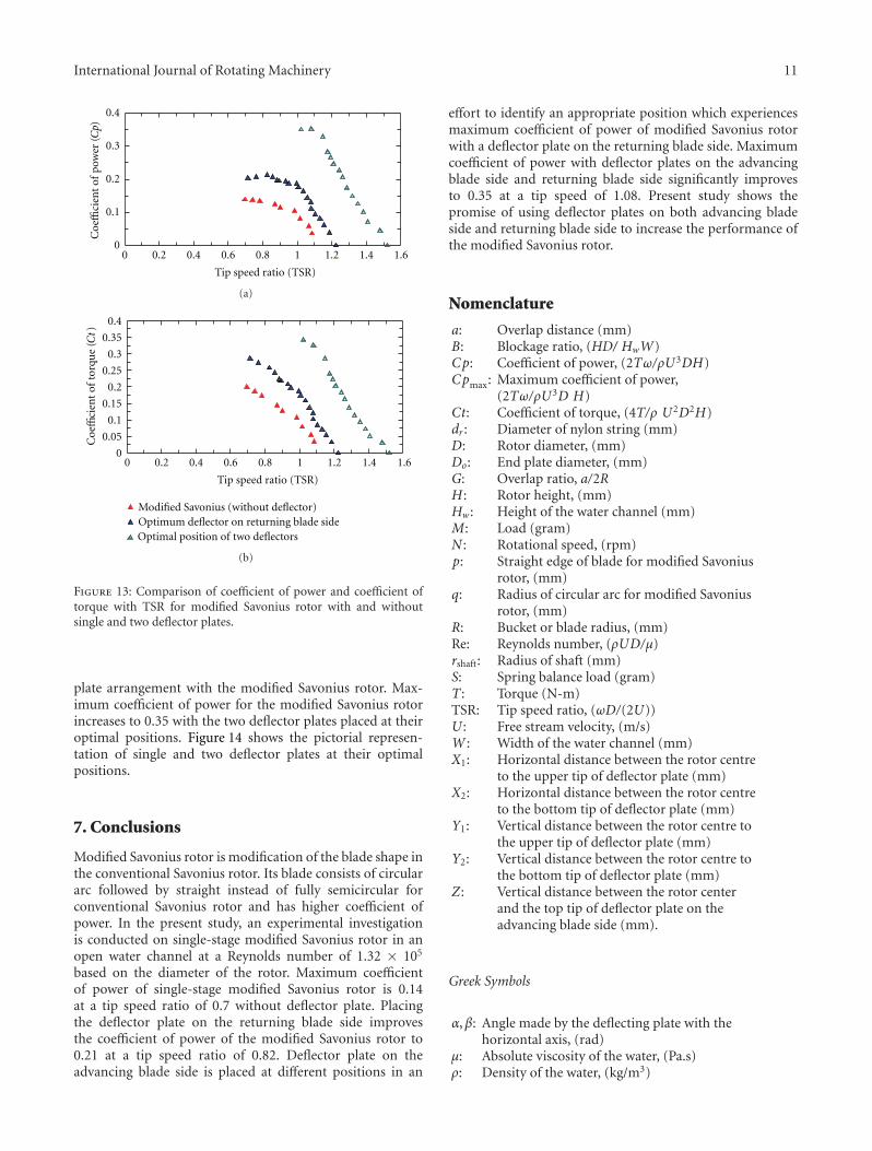
Figure 13 shows the variation of coefficient of power andcoefficient of torque with TSR for the rotor without deflectorplates, rotor with single deflector plate, and the rotor withtwo deflector plates at their optimal positions. Comparisonof coefficient of power and coefficient of torque for themodified Savonius rotor with and without deflector platesis given in Table 4. The coefficient of power and coefficientof torque improve significantly for the optimum deflector
International Journal of Rotating Machinery 11
0 0.2 0.4 0.6 0.8 1 1.2 1.4 1.6
Tip speed ratio (TSR)
0
0.1
0.2
0.3
0.4
Coe
ffici
ent
of p
ower
(Cp)
(a)
Modified Savonius (without deflector)Optimum deflector on returning blade sideOptimal position of two deflectors
0 0.2 0.4 0.6 0.8 1 1.2 1.4 1.6
Tip speed ratio (TSR)
0
0.05
0.1
0.15
0.2
0.25
0.3
0.35
0.4
Coe
ffici
ent
of to
rqu
e (Ct)
(b)
Figure 13: Comparison of coefficient of power and coefficient oftorque with TSR for modified Savonius rotor with and withoutsingle and two deflector plates.
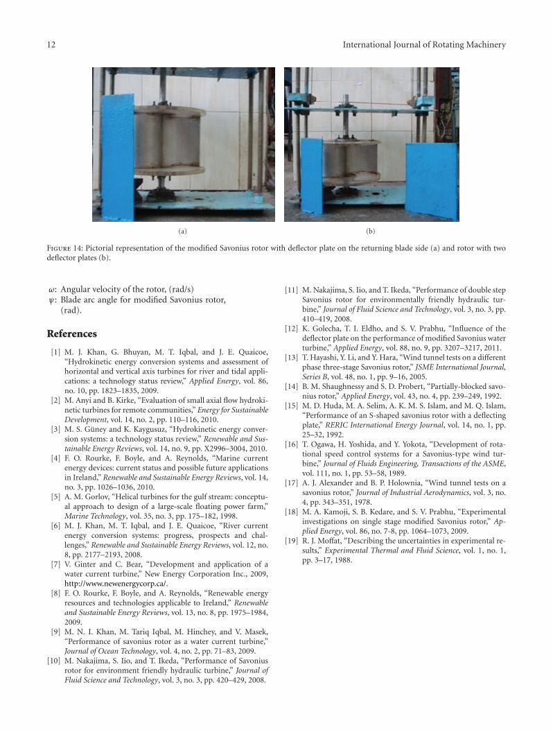
plate arrangement with the modified Savonius rotor. Max-imum coefficient of power for the modified Savonius rotorincreases to 0.35 with the two deflector plates placed at theiroptimal positions. Figure 14 shows the pictorial represen-tation of single and two deflector plates at their optimalpositions.
7. Conclusions
Modified Savonius rotor is modification of the blade shape inthe conventional Savonius rotor. Its blade consists of circulararc followed by straight instead of fully semicircular forconventional Savonius rotor and has higher coefficient ofpower. In the present study, an experimental investigationis conducted on single-stage modified Savonius rotor in anopen water channel at a Reynolds number of 1.32 × 10⁵
based on the diameter of the rotor. Maximum coefficientof power of single-stage modified Savonius rotor is 0.14at a tip speed ratio of 0.7 without deflector plate. Placingthe deflector plate on the returning blade side improvesthe coefficient of power of the modified Savonius rotor to0.21 at a tip speed ratio of 0.82. Deflector plate on theadvancing blade side is placed at different positions in an
effort to identify an appropriate position which experiencesmaximum coefficient of power of modified Savonius rotorwith a deflector plate on the returning blade side. Maximumcoefficient of power with deflector plates on the advancingblade side and returning blade side significantly improvesto 0.35 at a tip speed of 1.08. Present study shows thepromise of using deflector plates on both advancing bladeside and returning blade side to increase the performance ofthe modified Savonius rotor.
Nomenclature
a: Overlap distance (mm)B: Blockage ratio, (HD/ HwW)Cp: Coefficient of power, (2Tω/ρU3DH)Cpmax: Maximum coefficient of power,
(2Tω/ρU3D H)Ct: Coefficient of torque, (4T/ρ U2D2H)dr : Diameter of nylon string (mm)D: Rotor diameter, (mm)Do: End plate diameter, (mm)G: Overlap ratio, a/2RH : Rotor height, (mm)Hw: Height of the water channel (mm)M: Load (gram)N : Rotational speed, (rpm)p: Straight edge of blade for modified Savonius
rotor, (mm)q: Radius of circular arc for modified Savonius
rotor, (mm)R: Bucket or blade radius, (mm)Re: Reynolds number, (ρUD/μ)rshaft: Radius of shaft (mm)S: Spring balance load (gram)T : Torque (N-m)TSR: Tip speed ratio, (ωD/(2U))U : Free stream velocity, (m/s)W : Width of the water channel (mm)X1: Horizontal distance between the rotor centre
to the upper tip of deflector plate (mm)X2: Horizontal distance between the rotor centre
to the bottom tip of deflector plate (mm)Y1: Vertical distance between the rotor centre to
the upper tip of deflector plate (mm)Y2: Vertical distance between the rotor centre to
the bottom tip of deflector plate (mm)Z: Vertical distance between the rotor center
and the top tip of deflector plate on theadvancing blade side (mm).
Greek Symbols
α,β: Angle made by the deflecting plate with thehorizontal axis, (rad)
μ: Absolute viscosity of the water, (Pa.s)ρ: Density of the water, (kg/m3)
12 International Journal of Rotating Machinery
(a) (b)
Figure 14: Pictorial representation of the modified Savonius rotor with deflector plate on the returning blade side (a) and rotor with twodeflector plates (b).
ω: Angular velocity of the rotor, (rad/s)ψ: Blade arc angle for modified Savonius rotor,
(rad).
References
[1] M. J. Khan, G. Bhuyan, M. T. Iqbal, and J. E. Quaicoe,“Hydrokinetic energy conversion systems and assessment ofhorizontal and vertical axis turbines for river and tidal appli-cations: a technology status review,” Applied Energy, vol. 86,no. 10, pp. 1823–1835, 2009.
[2] M. Anyi and B. Kirke, “Evaluation of small axial flow hydroki-netic turbines for remote communities,” Energy for SustainableDevelopment, vol. 14, no. 2, pp. 110–116, 2010.
[3] M. S. Guney and K. Kaygusuz, “Hydrokinetic energy conver-sion systems: a technology status review,” Renewable and Sus-tainable Energy Reviews, vol. 14, no. 9, pp. X2996–3004, 2010.
[4] F. O. Rourke, F. Boyle, and A. Reynolds, “Marine currentenergy devices: current status and possible future applicationsin Ireland,” Renewable and Sustainable Energy Reviews, vol. 14,no. 3, pp. 1026–1036, 2010.
[5] A. M. Gorlov, “Helical turbines for the gulf stream: conceptu-al approach to design of a large-scale floating power farm,”Marine Technology, vol. 35, no. 3, pp. 175–182, 1998.
[6] M. J. Khan, M. T. Iqbal, and J. E. Quaicoe, “River currentenergy conversion systems: progress, prospects and chal-lenges,” Renewable and Sustainable Energy Reviews, vol. 12, no.8, pp. 2177–2193, 2008.
[7] V. Ginter and C. Bear, “Development and application of awater current turbine,” New Energy Corporation Inc., 2009,http://www.newenergycorp.ca/.
[8] F. O. Rourke, F. Boyle, and A. Reynolds, “Renewable energyresources and technologies applicable to Ireland,” Renewableand Sustainable Energy Reviews, vol. 13, no. 8, pp. 1975–1984,2009.
[9] M. N. I. Khan, M. Tariq Iqbal, M. Hinchey, and V. Masek,“Performance of savonius rotor as a water current turbine,”Journal of Ocean Technology, vol. 4, no. 2, pp. 71–83, 2009.
[10] M. Nakajima, S. Iio, and T. Ikeda, “Performance of Savoniusrotor for environment friendly hydraulic turbine,” Journal ofFluid Science and Technology, vol. 3, no. 3, pp. 420–429, 2008.
[11] M. Nakajima, S. Iio, and T. Ikeda, “Performance of double stepSavonius rotor for environmentally friendly hydraulic tur-bine,” Journal of Fluid Science and Technology, vol. 3, no. 3, pp.410–419, 2008.
[12] K. Golecha, T. I. Eldho, and S. V. Prabhu, “Influence of thedeflector plate on the performance of modified Savonius waterturbine,” Applied Energy, vol. 88, no. 9, pp. 3207–3217, 2011.
[13] T. Hayashi, Y. Li, and Y. Hara, “Wind tunnel tests on a differentphase three-stage Savonius rotor,” JSME International Journal,Series B, vol. 48, no. 1, pp. 9–16, 2005.
[14] B. M. Shaughnessy and S. D. Probert, “Partially-blocked savo-nius rotor,” Applied Energy, vol. 43, no. 4, pp. 239–249, 1992.
[15] M. D. Huda, M. A. Selim, A. K. M. S. Islam, and M. Q. Islam,“Performance of an S-shaped savonius rotor with a deflectingplate,” RERIC International Energy Journal, vol. 14, no. 1, pp.25–32, 1992.
[16] T. Ogawa, H. Yoshida, and Y. Yokota, “Development of rota-tional speed control systems for a Savonius-type wind tur-bine,” Journal of Fluids Engineering, Transactions of the ASME,vol. 111, no. 1, pp. 53–58, 1989.
[17] A. J. Alexander and B. P. Holownia, “Wind tunnel tests on asavonius rotor,” Journal of Industrial Aerodynamics, vol. 3, no.4, pp. 343–351, 1978.
[18] M. A. Kamoji, S. B. Kedare, and S. V. Prabhu, “Experimentalinvestigations on single stage modified Savonius rotor,” Ap-plied Energy, vol. 86, no. 7-8, pp. 1064–1073, 2009.
[19] R. J. Moffat, “Describing the uncertainties in experimental re-sults,” Experimental Thermal and Fluid Science, vol. 1, no. 1,pp. 3–17, 1988.

International Journal of
AerospaceEngineeringHindawi Publishing Corporationhttp://www.hindawi.com Volume 2010
RoboticsJournal of
Hindawi Publishing Corporationhttp://www.hindawi.com Volume 2014
Hindawi Publishing Corporationhttp://www.hindawi.com Volume 2014
Active and Passive Electronic Components
Control Scienceand Engineering
Journal of
Hindawi Publishing Corporationhttp://www.hindawi.com Volume 2014
International Journal of
RotatingMachinery
Hindawi Publishing Corporationhttp://www.hindawi.com Volume 2014
Hindawi Publishing Corporation http://www.hindawi.com
Journal ofEngineeringVolume 2014
Submit your manuscripts athttp://www.hindawi.com
VLSI Design
Hindawi Publishing Corporationhttp://www.hindawi.com Volume 2014
Hindawi Publishing Corporationhttp://www.hindawi.com Volume 2014
Shock and Vibration
Hindawi Publishing Corporationhttp://www.hindawi.com Volume 2014
Civil EngineeringAdvances in
Acoustics and VibrationAdvances in
Hindawi Publishing Corporationhttp://www.hindawi.com Volume 2014
Hindawi Publishing Corporationhttp://www.hindawi.com Volume 2014
Electrical and Computer Engineering
Journal of
Advances inOptoElectronics
Hindawi Publishing Corporation http://www.hindawi.com
Volume 2014
The Scientific World JournalHindawi Publishing Corporation http://www.hindawi.com Volume 2014
SensorsJournal of
Hindawi Publishing Corporationhttp://www.hindawi.com Volume 2014
Modelling & Simulation in EngineeringHindawi Publishing Corporation http://www.hindawi.com Volume 2014
Hindawi Publishing Corporationhttp://www.hindawi.com Volume 2014
Chemical EngineeringInternational Journal of Antennas and
Propagation
International Journal of
Hindawi Publishing Corporationhttp://www.hindawi.com Volume 2014
Hindawi Publishing Corporationhttp://www.hindawi.com Volume 2014
Navigation and Observation
International Journal of
Hindawi Publishing Corporationhttp://www.hindawi.com Volume 2014
DistributedSensor Networks
International Journal of