performance-based design of gravity … · performance-based design of gravity retaining walls...
TRANSCRIPT
E. Cosenza (ed), Eurocode 8 Perspectives from the Italian Standpoint Workshop, 277-289, © 2009 Doppiavoce, Napoli, Italy
PERFORMANCE-BASED DESIGN OF GRAVITY RETAINING WALLS UNDER SEISMIC ACTIONS
Armando Lucio Simonelli a, Augusto Penna a,b
a University of Sannio, Benevento, Italy, [email protected] b CIMA-AMRA Research Center, Sant’Angelo dei Lombardi, Italy, [email protected]
ABSTRACT This paper is devoted to the performance-based design of retaining walls under seismic actions. EC8 takes into account this kind of approach, both encouraging the utilization of dynamic analyses, and proposing reduction factor r in the simple pseudostatic method, whose value depends on the amount of “displacement” tolerable by the structure. In the recent Italian Building Code (2008) a better calibration of the seismic coefficients for the pseudostatic approach has been produced, based on the results of specific displacement analyses. According to the results obtained, it would be necessary to recalibrate the seismic coefficient now proposed in EC8. In this paper a further improvement in the design procedure of retaining walls is proposed, still based on the performance evaluation, which more effectively takes into account the principle of the “capacity design”, widely applied in structural design.
KEYWORDS Retaining walls, PBD, simplified dynamic analysis, pseudostatic design, capacity design.
1 INTRODUCTION
This paper deals with the performance-based design of retaining walls under seismic actions. In the first part of the paper the present version of Eurocode 8, and specifically EC8-Part5, is illustrated. The Code takes into account the performance criteria, both encouraging the utilization of dynamic analyses which allow to forecast the behaviour of the wall under real excitations, and proposing reduction factor r in the simple pseudostatic method, whose value depends on the amount of “displacement” tolerable by the structure. In the second part of the paper, after a discussion on the effects of the application of EC8 design rules for retaining wall, the recent studies performed in Italy by the Associazione Geotecnica Italiana (AGI) on these topics are briefly referred to. Then the recent Italian Building Code (Norme Tecniche per le Costruzioni, D.M. 14/01/2008, alias NTC2008) is illustrated in detail, since it derives from EC8 and could be practically considered as a first national application of Eurocodes, although with some significant improvements. As regards retaining walls, it propose a calibration of the seismic coefficient for the pseudostatic approach, based on the results of specific displacement analyses. In the last part of the paper, a further improvement in the design procedure of retaining walls is proposed, still based on the performance evaluation, which more effectively takes into account the principle of the “capacity design”, widely applied in structural design.
A.L. Simonelli, A. Penna
278
2 EUROCODE 8: RETAINING WALL DESIGN
The design of retaining walls is dealt with in Ch. 7 of Eurocode8-Part 5 (EN1998-5, FINAL DRAFT, December 2003, alias EC8-5); a detailed discussion on the whole chapter is illustrated in Simonelli (2003). At the beginning of ch. 7.1 “General requirements”, clause (2) it is stated that “Permanent displacements, in the form of combined sliding and tilting, the latter due to irreversible deformation of the foundation soil, may be acceptable if it is shown that they are compatible with functional and/or aesthetic requirements”. This concept is very important, and will be taken into account later in the evaluation of the pseudo-static seismic action on the structure. The methods of analysis are dealt with in Ch. 7.3, and it is stated that: “Any established method based on the procedures of structural and soil dynamics, and supported by experience and observations, is in principle acceptable for assessing the safety of an earth retaining structure” (Ch. 7.3.1, clause (1)P). After this foreword, particular attention is devoted to the pseudo-static analysis, regarded as the main simplified method (Ch. 7.3.2).
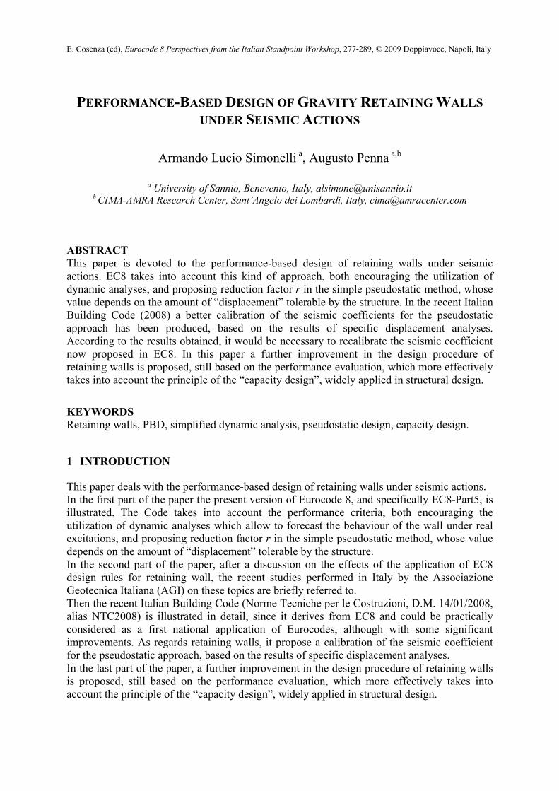
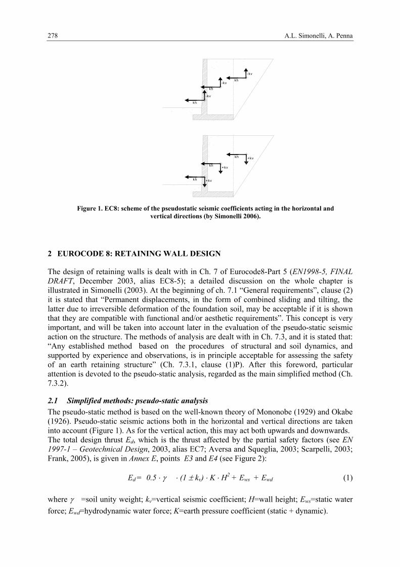
2.1 Simplified methods: pseudo-static analysis The pseudo-static method is based on the well-known theory of Mononobe (1929) and Okabe (1926). Pseudo-static seismic actions both in the horizontal and vertical directions are taken into account (Figure 1). As for the vertical action, this may act both upwards and downwards. The total design thrust Ed, which is the thrust affected by the partial safety factors (see EN 1997-1 – Geotechnical Design, 2003, alias EC7; Aversa and Squeglia, 2003; Scarpelli, 2003; Frank, 2005), is given in Annex E, points E3 and E4 (see Figure 2):
Ed = 0.5 ⋅ γ ⋅ (1 ± kv) ⋅ K ⋅ H2 + Ews + Ewd (1)
where γ =soil unity weight; kv=vertical seismic coefficient; H=wall height; Ews=static water force; Ewd=hydrodynamic water force; K=earth pressure coefficient (static + dynamic).
-kv
kh
kh
kh
-kv
-kv
kh
kh
kh
+kv
+kv
+kv
Figure 1. EC8: scheme of the pseudostatic seismic coefficients acting in the horizontal and vertical directions (by Simonelli 2006).
Performance-Based Design of Gravity Retaining Walls under Seismic Actions
279
The vertical seismic coefficient kv is a function of the horizontal one kh :
kv = ± 0.33 ⋅ kh or kv = ± 0.5 ⋅ kh (2)
depending on the ratio between the vertical and horizontal design accelerations (avg and ag), being respectively lower or larger than 0,6 (see EC8-5, ch. 7.3.2.2, clause (4)P). The horizontal seismic coefficient kh is:
kh = agR ⋅ γI ⋅ S / (g ⋅ r) (3)
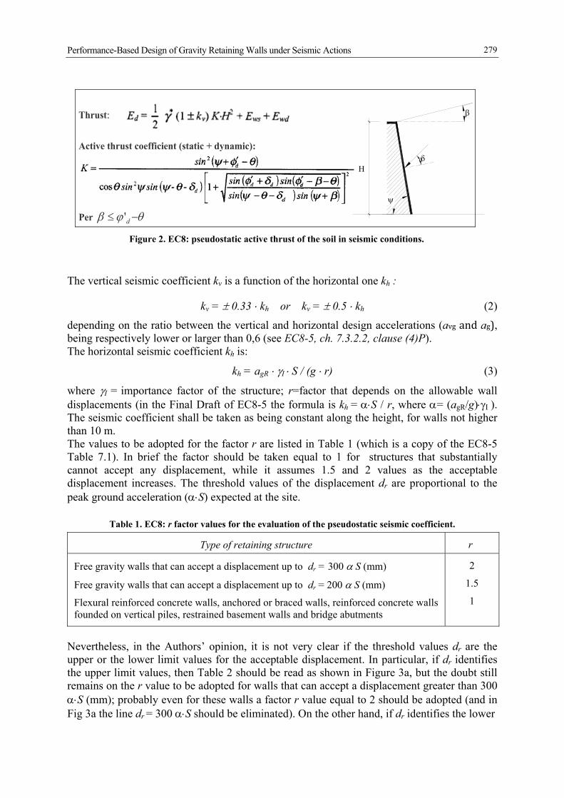
where γI = importance factor of the structure; r=factor that depends on the allowable wall displacements (in the Final Draft of EC8-5 the formula is kh = α⋅S / r, where α= (agR/g)⋅γI ). The seismic coefficient shall be taken as being constant along the height, for walls not higher than 10 m. The values to be adopted for the factor r are listed in Table 1 (which is a copy of the EC8-5 Table 7.1). In brief the factor should be taken equal to 1 for structures that substantially cannot accept any displacement, while it assumes 1.5 and 2 values as the acceptable displacement increases. The threshold values of the displacement dr are proportional to the peak ground acceleration (α⋅S) expected at the site.
Table 1. EC8: r factor values for the evaluation of the pseudostatic seismic coefficient.
Type of retaining structure r
Free gravity walls that can accept a displacement up to dr = 300 α S (mm)
Free gravity walls that can accept a displacement up to dr = 200 α S (mm)
Flexural reinforced concrete walls, anchored or braced walls, reinforced concrete walls founded on vertical piles, restrained basement walls and bridge abutments
2
1.5
1
Nevertheless, in the Authors’ opinion, it is not very clear if the threshold values dr are the upper or the lower limit values for the acceptable displacement. In particular, if dr identifies the upper limit values, then Table 2 should be read as shown in Figure 3a, but the doubt still remains on the r value to be adopted for walls that can accept a displacement greater than 300 α⋅S (mm); probably even for these walls a factor r value equal to 2 should be adopted (and in Fig 3a the line dr = 300 α⋅S should be eliminated). On the other hand, if dr identifies the lower
Figure 2. EC8: pseudostatic active thrust of the soil in seismic conditions.
Thrust:
δ
ψ
β
Η
Active thrust coefficient (static + dynamic):
Per θϕβ −≤ d'
d
A.L. Simonelli, A. Penna
280
limit values for the acceptable displacement, then Table 2 should be read as shown in Figure 3b, but the doubt still remains on the r value to be adopted for walls that can accept a displacement lower than 200 α⋅S (mm); moreover, in this case, the threshold condition dr = 300 α⋅S (mm) for applying r=2 would be quite severe, implying very large acceptable displacement values for the walls. In summary, the intensity of the pseudostatic force depends on the value of the ground surface acceleration ag⋅S and on the amount of allowable displacement of the wall (by means of the factor r). As regards the point of application of the force due to the dynamic earth pressures, it must be taken at mid-height of the wall, in the absence of a more detailed study taking into account the relative stiffness, the type of movements and the relative mass of the retaining structure. Only for walls which are free to rotate about their toe, the dynamic force may be taken to act at the same point as the static force. As regards the inclination of the thrust on the wall due to the static and the dynamic action, it can not be taken greater than (2/3)φ' for the active state, and must be taken equal to zero for the passive state. The equation of the active earth pressure coefficient K is given in Figure 2, where the symbols are ϕ’d = design value of the soil friction angle; δd = design value of the wall-soil friction angle; θ = inclination of the mass forces acting on the soil wedge. For dry soil θ is given by the equation:
v
h
kktan∓1
=ϑ (4)
For saturated soils the expression of θ changes for the two cases of low and high permeability soil under dynamic actions (see Annex E), and proper values of Ews and Ewd must be taken into account; it is worthwhile to underline that in any case the soil strength is always computed in drained conditions. Once the design action Ed has been determined, the wall must be verified against the sliding and bearing capacity failures: in both cases, Ed must be lower or equal to the design resistance Rd, which is the resistance affected by the partial safety factors:
Rd ≥ Ed (5)
0
50
100
150
0.00 0.10 0.20 0.30 0.40 0.50
α S
dmax
(mm
)
300 α S
200 α Sr = 2
r = 1,5
r = ?
dam
m (m
m)
α S (g)
d r (m
m)
0
50
100
150
0.00 0.10 0.20 0.30 0.40 0.50
α S
dmax
(mm
)
300 α S
200 α Sr = ?
r = 2
r = 1,5
dam
m (m
m)
α S (g)
d r (m
m)
(a) (b)
Figure 3. Graphic interpretations of the correlation among the r factor, the acceptable displacement dr (free gravity wall) and the peak ground acceleration, listed in Table 1 (by Simonelli, 2006).
Performance-Based Design of Gravity Retaining Walls under Seismic Actions
281
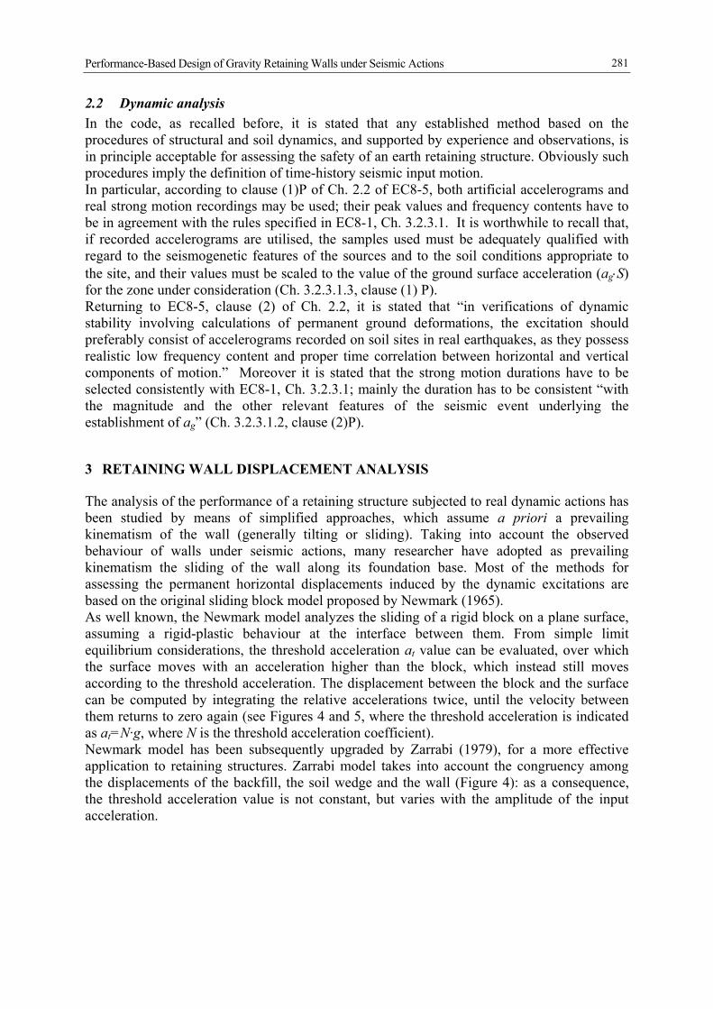
2.2 Dynamic analysis In the code, as recalled before, it is stated that any established method based on the procedures of structural and soil dynamics, and supported by experience and observations, is in principle acceptable for assessing the safety of an earth retaining structure. Obviously such procedures imply the definition of time-history seismic input motion. In particular, according to clause (1)P of Ch. 2.2 of EC8-5, both artificial accelerograms and real strong motion recordings may be used; their peak values and frequency contents have to be in agreement with the rules specified in EC8-1, Ch. 3.2.3.1. It is worthwhile to recall that, if recorded accelerograms are utilised, the samples used must be adequately qualified with regard to the seismogenetic features of the sources and to the soil conditions appropriate to the site, and their values must be scaled to the value of the ground surface acceleration (ag⋅S) for the zone under consideration (Ch. 3.2.3.1.3, clause (1) P). Returning to EC8-5, clause (2) of Ch. 2.2, it is stated that “in verifications of dynamic stability involving calculations of permanent ground deformations, the excitation should preferably consist of accelerograms recorded on soil sites in real earthquakes, as they possess realistic low frequency content and proper time correlation between horizontal and vertical components of motion.” Moreover it is stated that the strong motion durations have to be selected consistently with EC8-1, Ch. 3.2.3.1; mainly the duration has to be consistent “with the magnitude and the other relevant features of the seismic event underlying the establishment of ag” (Ch. 3.2.3.1.2, clause (2)P).
3 RETAINING WALL DISPLACEMENT ANALYSIS
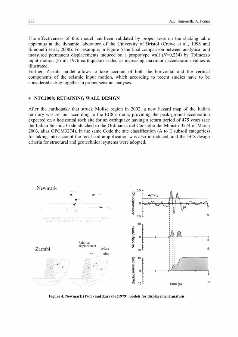
The analysis of the performance of a retaining structure subjected to real dynamic actions has been studied by means of simplified approaches, which assume a priori a prevailing kinematism of the wall (generally tilting or sliding). Taking into account the observed behaviour of walls under seismic actions, many researcher have adopted as prevailing kinematism the sliding of the wall along its foundation base. Most of the methods for assessing the permanent horizontal displacements induced by the dynamic excitations are based on the original sliding block model proposed by Newmark (1965). As well known, the Newmark model analyzes the sliding of a rigid block on a plane surface, assuming a rigid-plastic behaviour at the interface between them. From simple limit equilibrium considerations, the threshold acceleration at value can be evaluated, over which the surface moves with an acceleration higher than the block, which instead still moves according to the threshold acceleration. The displacement between the block and the surface can be computed by integrating the relative accelerations twice, until the velocity between them returns to zero again (see Figures 4 and 5, where the threshold acceleration is indicated as at=N·g, where N is the threshold acceleration coefficient). Newmark model has been subsequently upgraded by Zarrabi (1979), for a more effective application to retaining structures. Zarrabi model takes into account the congruency among the displacements of the backfill, the soil wedge and the wall (Figure 4): as a consequence, the threshold acceleration value is not constant, but varies with the amplitude of the input acceleration.
A.L. Simonelli, A. Penna
282
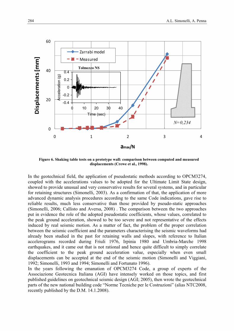
The effectiveness of this model has been validated by proper tests on the shaking table apparatus at the dynamic laboratory of the University of Bristol (Crewe et al., 1998 and Simonelli et al., 2000). For example, in Figure 6 the final comparison between analytical and measured permanent displacements induced on a proptotype wall (N=0,234) by Tolmezzo input motion (Friuli 1976 earthquake) scaled at increasing maximum acceleration values is illustrated. Further, Zarrabi model allows to take account of both the horizontal and the vertical components of the seismic input motion, which according to recent studies have to be considered acting together in proper seismic analyses.
4 NTC2008: RETAINING WALL DESIGN
After the earthquake that struck Molise region in 2002, a new hazard map of the Italian territory was set out according to the EC8 criteria, providing the peak ground acceleration expected on a horizontal rock site for an earthquake having a return period of 475 years (see the Italian Seismic Code attached to the Ordinanza del Consiglio dei Ministri 3274 of March 2003, alias OPCM3274). In the same Code the site classification (A to E subsoil categories) for taking into account the local soil amplification was also introduced, and the EC8 design criteria for structural and geotechnical systems were adopted.
Zarrabi
Newmark
Relative displacement
beforeafter
at=N· g
Figure 4. Newmark (1965) and Zarrabi (1979) models for displacement analysis.
Performance-Based Design of Gravity Retaining Walls under Seismic Actions
283
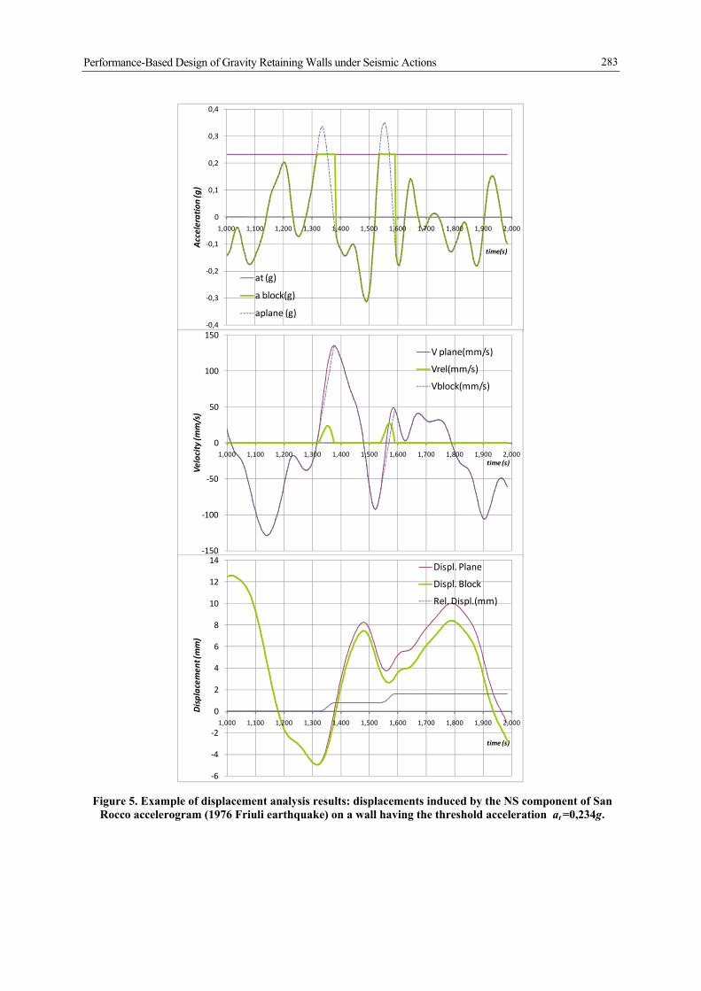
Figure 5. Example of displacement analysis results: displacements induced by the NS component of San Rocco accelerogram (1976 Friuli earthquake) on a wall having the threshold acceleration at =0,234g.
‐0,4
‐0,3
‐0,2
‐0,1
0
0,1
0,2
0,3
0,4
1,000 1,100 1,200 1,300 1,400 1,500 1,600 1,700 1,800 1,900 2,000
Acceleration (g)
time(s)
at (g)
a block(g)
aplane (g)
‐150
‐100
‐50
0
50
100
150
1,000 1,100 1,200 1,300 1,400 1,500 1,600 1,700 1,800 1,900 2,000
Velocity (m
m/s)
time (s)
V plane(mm/s)
Vrel(mm/s)
Vblock(mm/s)
‐6
‐4
‐2
0
2
4
6
8
10
12
14
1,000 1,100 1,200 1,300 1,400 1,500 1,600 1,700 1,800 1,900 2,000
Displacem
ent (mm)
time (s)
Displ. Plane
Displ. Block
Rel. Displ.(mm)
A.L. Simonelli, A. Penna
284
In the geotechnical field, the application of pseudostatic methods according to OPCM3274, coupled with the accelerations values to be adopted for the Ultimate Limit State design, showed to provide unusual and very conservative results for several systems, and in particular for retaining structures (Simonelli, 2003). As a confirmation of that, the application of more advanced dynamic analysis procedures according to the same Code indications, gave rise to reliable results, much less conservative than those provided by pseudo-static approaches (Simonelli, 2006; Callisto and Aversa, 2008) . The comparison between the two approaches put in evidence the role of the adopted pseudostatic coefficients, whose values, correlated to the peak ground acceleration, showed to be too severe and not representative of the effects induced by real seismic motion. As a matter of fact, the problem of the proper correlation between the seismic coefficient and the parameters characterising the seismic waveforms had already been studied in the past for retaining walls and slopes, with reference to Italian accelerograms recorded during Friuli 1976, Irpinia 1980 and Umbria-Marche 1998 earthquakes, and it came out that is not rational and hence quite difficult to simply correlate the coefficient to the peak ground acceleration value, especially when even small displacements can be accepted at the end of the seismic motion (Simonelli and Viggiani, 1992; Simonelli, 1993 and 1994; Simonelli and Fortunato 1996). In the years following the emanation of OPCM3274 Code, a group of experts of the Associazione Geotecnica Italiana (AGI) have intensely worked on those topics, and first published guidelines on geotechnical seismic design (AGI; 2005), then wrote the geotechnical parts of the new national building code “Norme Tecniche per le Costruzioni” (alias NTC2008, recently published by the D.M. 14.1.2008).
Figure 6. Shaking table tests on a prototype wall: comparison between computed and measured displacements (Crewe et al., 1998).
0
20
40
60
0 1 2 3 4
Displacemen
ts [m
m]
amax/N
Zarrabi model
Measured in test
N=0,234
Tolmezzo NS
-0.4
-0.2
0
0.2
0.4
0 10 20 30 40Time (sec)
Acce
lera
tion
(g)
Performance-Based Design of Gravity Retaining Walls under Seismic Actions
285
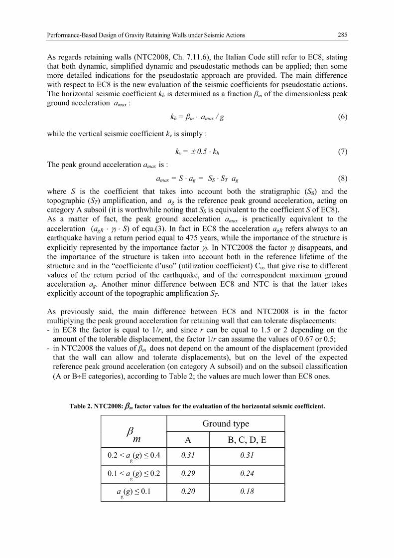
As regards retaining walls (NTC2008, Ch. 7.11.6), the Italian Code still refer to EC8, stating that both dynamic, simplified dynamic and pseudostatic methods can be applied; then some more detailed indications for the pseudostatic approach are provided. The main difference with respect to EC8 is the new evaluation of the seismic coefficients for pseudostatic actions. The horizontal seismic coefficient kh is determined as a fraction βm of the dimensionless peak ground acceleration amax :
kh = βm ⋅ amax / g (6)
while the vertical seismic coefficient kv is simply :
kv = ± 0.5 ⋅ kh (7)
The peak ground acceleration amax is :
amax = S ⋅ ag = SS ⋅ ST ag (8)
where S is the coefficient that takes into account both the stratigraphic (SS) and the topographic (ST) amplification, and ag is the reference peak ground acceleration, acting on category A subsoil (it is worthwhile noting that SS is equivalent to the coefficient S of EC8). As a matter of fact, the peak ground acceleration amax is practically equivalent to the acceleration (agR ⋅ γI ⋅ S) of equ.(3). In fact in EC8 the acceleration agR refers always to an earthquake having a return period equal to 475 years, while the importance of the structure is explicitly represented by the importance factor γI. In NTC2008 the factor γI disappears, and the importance of the structure is taken into account both in the reference lifetime of the structure and in the “coefficiente d’uso” (utilization coefficient) Cu, that give rise to different values of the return period of the earthquake, and of the correspondent maximum ground acceleration ag. Another minor difference between EC8 and NTC is that the latter takes explicitly account of the topographic amplification ST. As previously said, the main difference between EC8 and NTC2008 is in the factor multiplying the peak ground acceleration for retaining wall that can tolerate displacements: - in EC8 the factor is equal to 1/r, and since r can be equal to 1.5 or 2 depending on the
amount of the tolerable displacement, the factor 1/r can assume the values of 0.67 or 0.5; - in NTC2008 the values of βm does not depend on the amount of the displacement (provided
that the wall can allow and tolerate displacements), but on the level of the expected reference peak ground acceleration (on category A subsoil) and on the subsoil classification (A or B÷E categories), according to Table 2; the values are much lower than EC8 ones.
Table 2. NTC2008: βm factor values for the evaluation of the horizontal seismic coefficient.
Ground type β
m
A B, C, D, E 0.2 < a
g(g) ≤ 0.4 0.31 0.31
0.1 < ag(g) ≤ 0.2 0.29 0.24
ag(g) ≤ 0.1 0.20 0.18
A.L. Simonelli, A. Penna
286
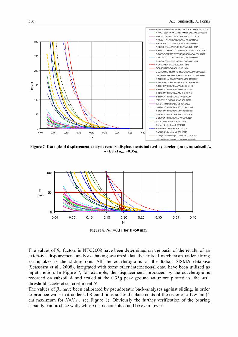
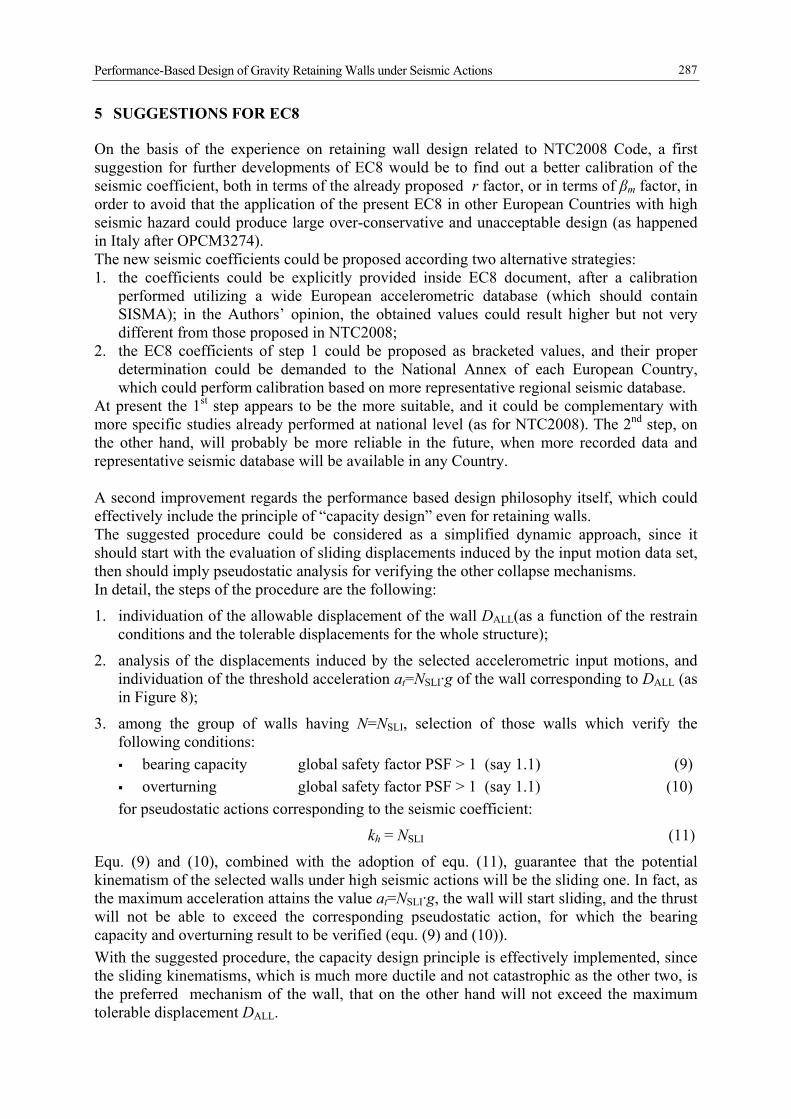
The values of βm factors in NTC2008 have been determined on the basis of the results of an extensive displacement analysis, having assumed that the critical mechanism under strong earthquakes is the sliding one. All the accelerograms of the Italian SISMA database (Scasserra et al., 2008), integrated with some other international data, have been utilized as input motion. In Figure 7, for example, the displacements produced by the accelerograms recorded on subsoil A and scaled at the 0.35g peak ground value are plotted vs. the wall threshold acceleration coefficient N. The values of βm have been calibrated by pseudostatic back-analyses against sliding, in order to produce walls that under ULS conditions suffer displacements of the order of a few cm (5 cm maximum for N=NSLI, see Figure 8). Obviously the further verification of the bearing capacity can produce walls whose displacements could be even lower.
0
50
100
150
200
250
300
0,00 0,05 0,10 0,15 0,20 0,25 0,30 0,35 0,40
D(m
m)
N(g)
A-TOLMEZZO -DIGA AMBIESTA EW SCALATA 0.35/0.35713
A-TOLMEZZO -DIGA AMBIESTA NS SCALATA 0.35/0.35713
A-VILLETTA BARREA EW SCALATA 0.35/0.19876
A-VILLETTA BARREA NS SCALATA 0.35/0.18173
A-ASSISI-STALLONE EW SCALATA 0.35/0.18847
A-ASSISI-STALLONE NS SCALATA 0.35/0.18847
B-BORGO-CERRETO-TORRE EW SCALATA 0.35/0.18497
B-BORGO-CERRETO-TORRE NS SCALATA 0.35/0.18497
E-ASSISI-STALLONE EW SCALATA 0.35/0.18814
E-ASSISI-STALLONE NS SCALATA 0.35/0.18814
F-CASCIA EW SCALATA 0.35/0.19876
F-CASCIA NS SCALATA 0.35/0.19876
J-BORGO-CERRETO-TORRE EW SCALATA 0.35/0.33833
J-BORGO-CERRETO-TORRE NS SCALATA 0.35/0.33833
R-NOCERA-UMBRA2 EW SCALATA 0.35/0.38041
R-NOCERA-UMBRA2 NS SCALATA 0.35/0.38041
R-BISCONTINI EW SCALATA 0.35/0.31148
R-BISCONTINI NS SCALATA 0.35/0.31148
S-BISCONTINI EW SCALATA 0.35/0.2254
S-BISCONTINI NS SCALATA 0.35/0.2254
TARCENTO EW SCALATA 0.35/0.21096
TARCENTO NS SCALATA 0.35/0.21096
C-BISCONTINI EW SCALATA 0.35/0.27332
C-BISCONTINI NS SCALATA 0.35/0.27332
E-BISCONTINI EW SCALATA 0.35/0.38281
E-BISCONTINI NS SCALATA 0.35/0.38281
Sturno EW - Scalato a 0.35/0.3205
Sturno NS - Scalato a 0.35/0.3205
Bagnoli EW - scalato a 0.35/0.18975
BAGNOLI NS scalata a 0.35/0.18975
Hercegnovi Montenegro EW scalata a 0.35/0.256
Hercegnovi Montenegro NS scalata a 0.35/0.256
Figure 7. Example of displacement analysis results: displacements induced by accelerograms on subsoil A, scaled at amax=0.35g.
N
Figure 8. NSLI=0,19 for D=50 mm.
0
50
100
0,00 0,05 0,10 0,15 0,20 0,25 0,30 0,35 0,40N(g)N
D (mm)
Performance-Based Design of Gravity Retaining Walls under Seismic Actions
287
5 SUGGESTIONS FOR EC8
On the basis of the experience on retaining wall design related to NTC2008 Code, a first suggestion for further developments of EC8 would be to find out a better calibration of the seismic coefficient, both in terms of the already proposed r factor, or in terms of βm factor, in order to avoid that the application of the present EC8 in other European Countries with high seismic hazard could produce large over-conservative and unacceptable design (as happened in Italy after OPCM3274). The new seismic coefficients could be proposed according two alternative strategies: 1. the coefficients could be explicitly provided inside EC8 document, after a calibration
performed utilizing a wide European accelerometric database (which should contain SISMA); in the Authors’ opinion, the obtained values could result higher but not very different from those proposed in NTC2008;
2. the EC8 coefficients of step 1 could be proposed as bracketed values, and their proper determination could be demanded to the National Annex of each European Country, which could perform calibration based on more representative regional seismic database.
At present the 1st step appears to be the more suitable, and it could be complementary with more specific studies already performed at national level (as for NTC2008). The 2nd step, on the other hand, will probably be more reliable in the future, when more recorded data and representative seismic database will be available in any Country. A second improvement regards the performance based design philosophy itself, which could effectively include the principle of “capacity design” even for retaining walls. The suggested procedure could be considered as a simplified dynamic approach, since it should start with the evaluation of sliding displacements induced by the input motion data set, then should imply pseudostatic analysis for verifying the other collapse mechanisms. In detail, the steps of the procedure are the following:
1. individuation of the allowable displacement of the wall DALL(as a function of the restrain conditions and the tolerable displacements for the whole structure);
2. analysis of the displacements induced by the selected accelerometric input motions, and individuation of the threshold acceleration at=NSLI·g of the wall corresponding to DALL (as in Figure 8);
3. among the group of walls having N=NSLI, selection of those walls which verify the following conditions: bearing capacity global safety factor PSF > 1 (say 1.1) (9) overturning global safety factor PSF > 1 (say 1.1) (10)
for pseudostatic actions corresponding to the seismic coefficient:
kh = NSLI (11)
Equ. (9) and (10), combined with the adoption of equ. (11), guarantee that the potential kinematism of the selected walls under high seismic actions will be the sliding one. In fact, as the maximum acceleration attains the value at=NSLI·g, the wall will start sliding, and the thrust will not be able to exceed the corresponding pseudostatic action, for which the bearing capacity and overturning result to be verified (equ. (9) and (10)). With the suggested procedure, the capacity design principle is effectively implemented, since the sliding kinematisms, which is much more ductile and not catastrophic as the other two, is the preferred mechanism of the wall, that on the other hand will not exceed the maximum tolerable displacement DALL.
A.L. Simonelli, A. Penna
288
6 CONCLUSIONS
In this paper the performance-based design of retaining walls under seismic actions has been dealt with, first reviewing the present version of Eurocode 8, then examining the indications of the recent Italian Building Code (D.M. 14/01/2008, alias NTC2008). Both EC8 and NTC2008, which practically derives from the Eurocode, take into account the performance based design criteria. In fact the codes encourage the utilization of dynamic analyses which allow to forecast the behaviour of the wall under real excitations; further they propose simple pseudostatic method, whose seismic coefficients depend on the amount of “displacement” tolerable by the structure. Nevertheless the application of EC8 rules to the Italian territory, coupled with the peak ground accelerations expected for high return period earthquakes (SLU conditions) showed to produce over-conservative design. On the other hand, in the recent NTC2008 a better calibration of the seismic coefficients for computing pseudostatic actions has been produced, on the basis of parametric displacement analyses performed adopting as input motion the Italian accelerometric database SISMA. These results suggest that in the next future a similar procedure should be implemented in EC8 too, with the aim to improve the effectiveness of the suggested pseudostatic methods. In this last part of the paper a simplified dynamic design procedure is proposed, still based on the performance evaluation, which more effectively takes into account the principle of the “capacity design” for retaining wall. According to the design procedure the sliding phenomenon, which is the more ductile and not catastrophic kinematism, becomes the potential mechanism under severe seismic motion, preventing the wall from bearing capacity and overturning collapse.
7 ACKNOWLEDGEMENTS
The work presented in this paper is part of the ReLUIS Research Project “Innovative methods for the design of geotechnical systems”, promoted and funded by the Department of Civil Protection (DPC) of the Italian Government and coordinated by the AGI (Italian Geotechnical Association).
8 REFERENCES
AGI - Associazione Geotecnica Italiana (2005). Linee Guida su “Gli aspetti geotecnici della progettazione antisismica”, Patron Editor, Bologna.
Aversa, S., and Squeglia, N. (2003). Il dimensionamento delle opera di sostegno. XXI Convegno Nazionale di Geotecnica "Opere Geotecniche in ambito urbano", L'Aquila, Volume 2, ISBN 88-555-2873-4
Callisto, L., and Aversa, S. (2008). Dimensionamento di opere di sostegno soggette ad azioni sismiche. XII Ciclo di Conferenze di Meccanica e Ingegneria delle Rocce “Opere Geotecniche in Condizioni Sismiche”, MIR 2008, Torino.
Crewe, A.J., Scotto di Santolo, A. and Simonelli, A.L. (1998). Shaking table tests of scale models of gravity retaining walls. The Sixth SECED Conference on Seismic Design Practice into the Next Century, Oxford, UK
D.M. 14.1.2008 del Ministero delle Infrastrutture. Nuove norme tecniche per le costruzioni (NTC, 2008). S.O. n. 30 alla G.U. del 4.2.2008, No. 29.
Performance-Based Design of Gravity Retaining Walls under Seismic Actions
289
EN 1997-1 (2002). Eurocode 7 Geotechnical Design – Part 1: General Rules. CEN European Committee for Standardization, Bruxelles, Belgium.
EN 1998-5 (December 2003). Eurocode 8: Design of structures for earthquake resistance – Part 5: Foundations, retaining structures and geotechnical aspects. CEN European Committee for Standardization, Bruxelles, Belgium.
Frank, R. (2005). Eurocodice 7: Progettazione geotecnica. Regole generali: Approccio concettuale e principi di base. Atti delle Conferenze di Geotecnica di Torino, XX Ciclo, Torino.
Mononobe, N. (1929). Earthquake proof construction of masonry dams. Proc. of World Conference, vol 9 Newmark, N. M. (1965). Effects of earthquake on dams and embankments. Geotechnique, n.15, pp. 139-
160 Okabe, S. (1926). General theory of earth pressure. Japanese Society of Civil Engineers, vol. 12, no. 1. OPCM n. 3274 (20/3/03) – Primi elementi in materia di criteri generali per la classificazione sismica
del territorio nazionale e di normative tecniche per le costruzioni in zona sismica. Gazzetta Ufficiale della Repubblica Italiana, n. 105 dell’8/5/03.
Scarpelli, G. (2003). I possibili approcci alla progettazione secondo l’Eurocodice 7. XXI Convegno Nazionale di Geotecnica "Opere Geotecniche in ambito urbano", L'Aquila, Volume 2, ISBN 88-555-2873-4.
Scasserra G., Lanzo G., Stewart J.P., D’Elia B. (2008). “SISMA (Site of Italian Strong-Motion Accelerograms): a web-database of ground motion recordings for engineering applications”, Seismic Engng. Conf. commemorating the 1908 Messina and Reggio Calabria Earthquake, Reggio Calabria, AIP, Melville, N.Y., Vol. 2, pp. 1649-1656; http://sisma.dsg.uniroma1.it.
Simonelli, A.L. (1993). Displacement analysis in earth slope design under seismic conditions, Proc. VI Conference on Soil Dynamics and Earthquake Engineering, Bath, CMP, Southampton & Elsevier, London.
Simonelli, A.L. (1994). Earth retaining wall displacement analysis under seismic conditions. X European Conference on Earthquake Engineering, Vienna
Simonelli, A.L. (2003). Eurocodice 8: valutazione delle azioni sismiche al suolo ed effetti sulla spinta dei terreni. XXI Convegno Nazionale di Geotecnica "Opere Geotecniche in ambito urbano", L'Aquila, Volume 2, ISBN 88-555-2873-4
Simonelli, A.L. (2006). Pseudo-static and pseudo-dynamic gravity wall design according to Eurocode 8. ETC12 Workshop on the “Evaluation of Eurocode 8”, Atene
Simonelli, A.L., Carafa, P., Feola, A., Crewe, A.J. and Taylor, C.A. (2000). Retaining walls under seismic actions: shaking table testing and numerical approaches. XII World Conference on Earthquake Engineering, Aukland, New Zealand
Simonelli, A.L., Fortunato E. (1996). Effects of earth slope characteristics on displacement based seismic design. Proc. 11 World Conference on Earthquake Engineering, Acapulco, Pergamon, Oxford.
Simonelli, A.L. and Viggiani, C. (1992). Some remarks on retaining wall design under seismic conditions. X World Conference on Earthquake Engineering, Madrid
Zarrabi-Kashani, K. (1979). Sliding of gravity retaining walls during earthquakes considering vertical acceleration and changing inclination of failure surface. M.S. Thesis, Dept. of Civil Eng., Massachusetts Institute of Technology, Cambridge