performance and limitations of photothermoplastic devices
TRANSCRIPT
This article was downloaded by: [New York University]On: 06 October 2014, At: 21:46Publisher: Taylor & FrancisInforma Ltd Registered in England and Wales Registered Number: 1072954 Registeredoffice: Mortimer House, 37-41 Mortimer Street, London W1T 3JH, UK
Optica Acta: International Journal ofOpticsPublication details, including instructions for authors andsubscription information:http://www.tandfonline.com/loi/tmop19
Performance and Limitations ofPhotothermoplastic DevicesU. Killat a & D.R. Terrell aa Philips GmbH Forschungslaboratorium Hamburg, 2000 Hamburg 54,BRDPublished online: 16 Nov 2010.
To cite this article: U. Killat & D.R. Terrell (1977) Performance and Limitations of PhotothermoplasticDevices, Optica Acta: International Journal of Optics, 24:4, 441-452, DOI: 10.1080/713819554
To link to this article: http://dx.doi.org/10.1080/713819554
PLEASE SCROLL DOWN FOR ARTICLE
Taylor & Francis makes every effort to ensure the accuracy of all the information (the“Content”) contained in the publications on our platform. However, Taylor & Francis,our agents, and our licensors make no representations or warranties whatsoever as tothe accuracy, completeness, or suitability for any purpose of the Content. Any opinionsand views expressed in this publication are the opinions and views of the authors,and are not the views of or endorsed by Taylor & Francis. The accuracy of the Contentshould not be relied upon and should be independently verified with primary sourcesof information. Taylor and Francis shall not be liable for any losses, actions, claims,proceedings, demands, costs, expenses, damages, and other liabilities whatsoever orhowsoever caused arising directly or indirectly in connection with, in relation to or arisingout of the use of the Content.
This article may be used for research, teaching, and private study purposes. Anysubstantial or systematic reproduction, redistribution, reselling, loan, sub-licensing,systematic supply, or distribution in any form to anyone is expressly forbidden. Terms &Conditions of access and use can be found at http://www.tandfonline.com/page/terms-and-conditions
OPTICA ACTA, 1977, VOL . 24, NO . 4, 441-452
Performance and limitations of photothermoplastic devices
U. KILLAT and D . R. TERRELLPhilips GmbH Forschungslaboratorium Hamburg,2000 Hamburg 54, BRD
(Received 12 November 1976)
Abstract . The performance of photothermoplastics has been reviewed withrespect to sensitivity, resolution and diffraction efficiency . Particular attentionhas been given to the problems of linearity, the band-pass limited modulationtransfer function, and high cycling speed . The relation between signal andfrost is discussed qualitatively on the basis of a heuristic model .
Drawbacks of the system lie in the unwieldy and slow corona operation andthe critical dosage for heat development . Some recent improvements in thisdirection are reported .
1 . IntroductionHolographic recording in photothermoplastic devices (PTD's) has been
known for more than ten years [1] . PTD's have aroused considerable interestas re-usable, in situ working, real-time storage materials with principal appli-cations in the fields of holographic filtering [2], holographic interferometry[3-5], and optical memories [6-8] .
Ideally storage materials for such purposes should fulfil a number of require-ments, such as high resolution, high diffraction efficiency, high sensitivity, fastwriting times, rapid cycling, high stability, etc . PTD's do not possess all theseattributes, but have found widespread use as a result of simple and cheap fabri-cation, high diffraction efficiency and high sensitivity .
In this paper a brief review will be given of the performance of PTD's asholographic storage materials. In subsequent sections some long-term problemswill be discussed in the light of recent research, such as
the limitation of the resolution of thermoplastics by a band-pass frequencyresponse, which appears to be related to the so-called frost problem,
the severe restraints imposed upon the device by rapid operation, i .e . oncharging technique, sensitivity, heat supply and heat dissipation .
2 . Device fabricationA PTD configuration similar to that described in [6] has been used, comprising
a glass substrate successively coated with a transparent conductive layer, a photo-conductor layer and a thermoplastic layer . The transparent electrode consistsof tin dioxide doped with indium to reduce the layer resistance . It has been foundthat resistance homogeneity is crucial to the functioning of the PTD and that onlysputtering a fresh mixture of tin and indium oxides provided such homogeneity .
To exclude particulate contamination during the preparation of PTD 's thesolutions are filtered under pressure through fine filters (0 .6p pore diameter) andthe layers are dip-coated in a dust-free environment . Layer thicknesses could
Dow
nloa
ded
by [
New
Yor
k U
nive
rsity
] at
21:
46 0
6 O
ctob
er 2
014
442
U. Killat and D. R. Terell
be varied between 0-21L and 2[t by changes in the solution concentrations andpulling rates . Typical values for the thermoplastic and photoconductorthicknesses were 0 .4µm and 0 . 6µm, respectively .
The widely used Staybelite Ester 10 has been used as the thermoplastic inmost of our experiments, although preliminary experiments have also been carriedout with some (styrene-methacrylate) copolymers which exhibit promising vis-cosity temperature-characteristics [9] . Poly(N-vinyl carbazole) (PVK) dopedwith appropriate dyes for sensitization at 633 nm has been used as the photo-conductor .
3 . Holographic recordingHolograms are recorded by depositing a surface charge on the PTD surface
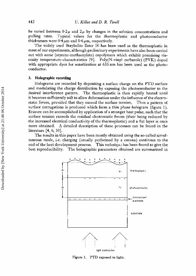
and modulating the charge distribution by exposing the photoconductor to thedesired interference pattern . The thermoplastic is then rapidly heated untilit becomes sufficiently soft to allow deformation under the influence of the electro-static forces, provided that they exceed the surface tension . Thus a pattern ofsurface corrugations is produced which form a thin phase hologram (figure 1) .Erasure can be accomplished by application of a stronger heat pulse, such that thesurface tension exceeds the residual electrostatic forces (their being reduced bythe increased electrical conductivity of the thermoplastic) and a flat layer is oncemore obtained. A detailed description of these processes can be found in theliterature [4, 6, 10] .
The results in this paper have been mostly obtained using the so-called simul-taneous mode, i .e. charging (usually performed by a corona) continues to theend of the heat development process . This technique has been found to give thebest reproducibility . The holographic parameters obtained are summarized in
Ep
light distribution
Figure 1 . PTD exposed to light.
thermoplastic
photoconductor
transparentelectrode
substrate
Dow
nloa
ded
by [
New
Yor
k U
nive
rsity
] at
21:
46 0
6 O
ctob
er 2
014
Performance and limitations of photothermoplastic devices
443
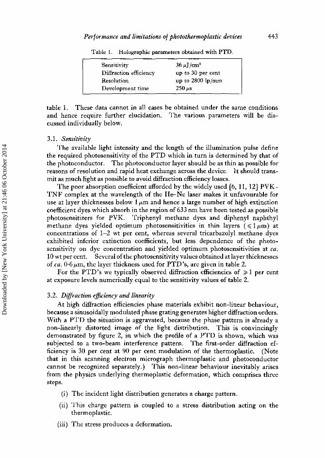
Table 1 . Holographic parameters obtained with PTD .
Sensitivity
36 µJ/cm'
Diffraction efficiency
up to 30 per centResolution
up to 2800 lp/mmDevelopment time
250µs
table 1 . These data cannot in all cases be obtained under the same conditionsand hence require further elucidation. The various parameters will be dis-cussed individually below .
3.1 . SensitivityThe available light intensity and the length of the illumination pulse define
the required photosensitivity of the PTD which in turn is determined by that ofthe photoconductor . The photoconductor layer should be as thin as possible forreasons of resolution and rapid heat exchange across the device . It should trans-mit as much light as possible to avoid diffraction efficiency losses .
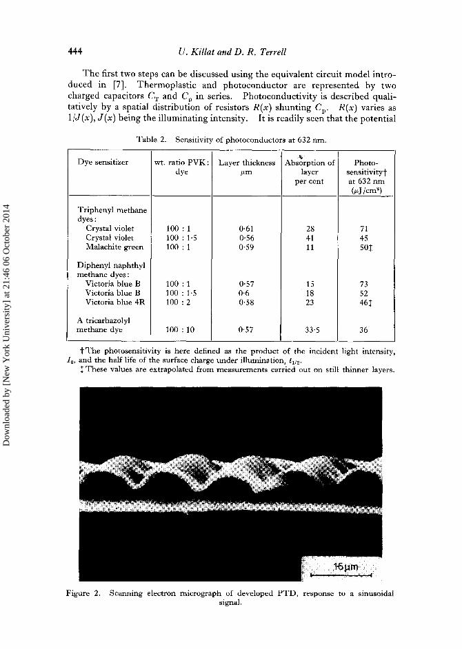
The poor absorption coefficient afforded by the widely used [6, 11, 12] PVK-TNF complex at the wavelength of the He-Ne laser makes it unfavourable foruse at layer thicknesses below 1 µm and hence a large number of high extinctioncoefficient dyes which absorb in the region of 633 nm have been tested as possiblephotosensitizers for PVK. Triphenyl methane dyes and diphenyl naphthylmethane dyes yielded optimum photosensitivities in thin layers ( < 1 µm) atconcentrations of 1-2 wt per cent, whereas several tricarbazolyl methane dyesexhibited inferior extinction coefficients, but less dependence of the photo-sensitivity on dye concentration and yielded optimum photosensitivities at ca .10 wt per cent. Several of the photosensitivity values obtained at layer thicknessesof ca . 0 . 6µm, the layer thickness used for PTD's, are given in table 2 .
For the PTD's we typically observed diffraction efficiencies of '>' 1 per centat exposure levels numerically equal to the sensitivity values of table 2 .
3.2 . Diffraction efficiency and linearityAt high diffraction efficiencies phase materials exhibit non-linear behaviour,
because a sinusoidally modulated phase grating generates higher diffraction orders .With a PTD the situation is aggravated, because the phase pattern is already anon-linearly distorted image of the light distribution . This is convincinglydemonstrated by figure 2, in which the profile of a PTD is shown, which wassubjected to a two-beam interference pattern . The first-order diffraction ef-ficiency is 30 per cent at 90 per cent modulation of the thermoplastic . (Notethat in this scanning electron micrograph thermoplastic and photoconductorcannot be recognized separately .) This non-linear behaviour inevitably arisesfrom the physics underlying thermoplastic deformation, which comprises threesteps .
(i) The incident light distribution generates a charge pattern .
(ii) This charge pattern is coupled to a stress distribution acting on thethermoplastic .
(iii) The stress produces a deformation .
Dow
nloa
ded
by [
New
Yor
k U
nive
rsity
] at
21:
46 0
6 O
ctob
er 2
014
444 U. Killat and D . R. Terrell
The first two steps can be discussed using the equivalent circuit model intro-duced in [7] . Thermoplastic and photoconductor are represented by twocharged capacitors CT and CP in series . Photoconductivity is described quali-tatively by a spatial distribution of resistors R(x) shunting C P . R(x) varies as1/J(x), J(x) being the illuminating intensity . It is readily seen that the potential
Table 2 . Sensitivity of photoconductors at 632 nm .
t The photosensitivity is here defined as the product of the incident light intensity,I,,, and the half life of the surface charge under illumination, t 12 .
1 These values are extrapolated from measurements carried out on still thinner layers .
Figure 2 . Scanning electron micrograph of developed PTD, response to a sinusoidalsignal .
Dye sensitizer wt. ratio PVK :dye
Layer thicknessµm
Absorption oflayer
per cent
Photo-sensitivitytat 632 nm(µJ /cm2)
Triphenyl methanedyes :
Crystal violet 100 : 1 0 . 61 28 71Crystal violet 100 : 1 . 5 0 . 56 41 45Malachite green 100 : 1 0 . 59 11 501
Diphenyl naphthylmethane dyes
Victoria blue B 100 : 1 0 . 57 15 73Victoria blue B 100 : 1 . 5 0 . 6 18 52Victoria blue 4R 100 : 2 0 .58 23 461
A tricarbazolylmethane dye 100 :10 0 .57 33 . 5 36
Dow
nloa
ded
by [
New
Yor
k U
nive
rsity
] at
21:
46 0
6 O
ctob
er 2
014
Performance and limitations o f photothermoplastic devices
445
across the photoconductor decreases exponentially with exposure . Thus thecharge pattern generated at the interface of thermoplastic and photoconductorwill be linearly related to the light pattern only if its amplitude is small comparedwith the charge density stored at the upper surface of the PTD .
This condition also applies to the second step . The stress exerted on thethermoplastic is proportional to the square of the electric field . For sufficientlysmall modulating charges the expressions for stress can be linearized and underthese conditions the stress distribution will be a true reproduction of the lightpattern .
In figure 2 the second harmonic content is approximately 25 per cent of thefundamental . This leads to an additional second-order contribution which is aslarge as that expected for a pure sine-wave grating of equal amplitude .
For modulating depths below 40 per cent no significant distortion of the defor-mation profile has been found . Non-linearities in thermoplastic recording can beneglected for most applications, provided that diffraction efficiencies are keptbelow 10 per cent.
3.3. Spatial frequency response
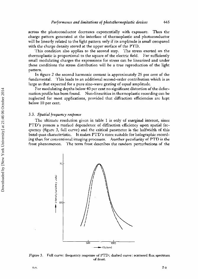
The ultimate resolution given in table 1 is only of marginal interest, sincePTD 's possess a marked dependence of diffraction efficiency upon spatial fre-quency (figure 3, full curve) and the critical parameter is the halfwidth of thisband-pass characteristic . It makes PTD 's more suitable for holographic record-ing than for conventional imaging processes . Another peculiarity of PTD is thefrost phenomenon . The term frost describes the random perturbations of the
1.0
500
flip/mm]
Figure 3 . Full curve : frequency response of PTD ; dashed curve : scattered flux spectrumof frost .
1000
Dow
nloa
ded
by [
New
Yor
k U
nive
rsity
] at
21:
46 0
6 O
ctob
er 2
014
446
U. Killat and D . R . Terrell
thermoplastic's surface which occur upon heating a thermoplastic layer that hasbeen charged to a certain potential .
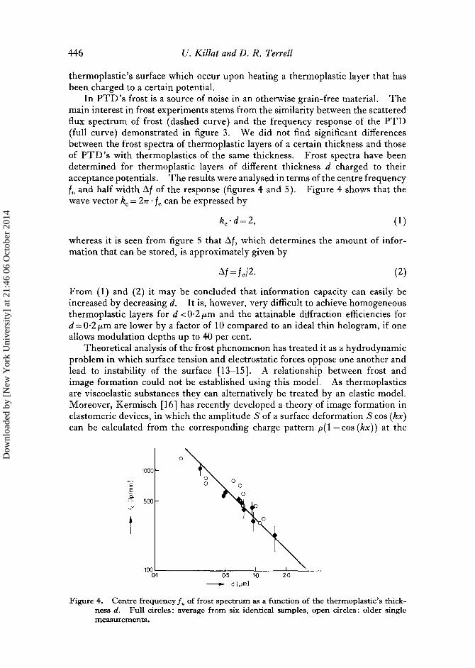
In PTD's frost is a source of noise in an otherwise grain-free material . Themain interest in frost experiments stems from the similarity between the scatteredflux spectrum of frost (dashed curve) and the frequency response of the PTD(full curve) demonstrated in figure 3 . We did not find significant differencesbetween the frost spectra of thermoplastic layers of a certain thickness and thoseof PTD's with thermoplastics of the same thickness . Frost spectra have beendetermined for thermoplastic layers of different thickness d charged to theiracceptance potentials . The results were analysed in terms of the centre frequencyf. and half width Of of the response (figures 4 and 5) . Figure 4 shows that thewave vector k0 = 2ir • f can be expressed by
k0 •d =2, (1)
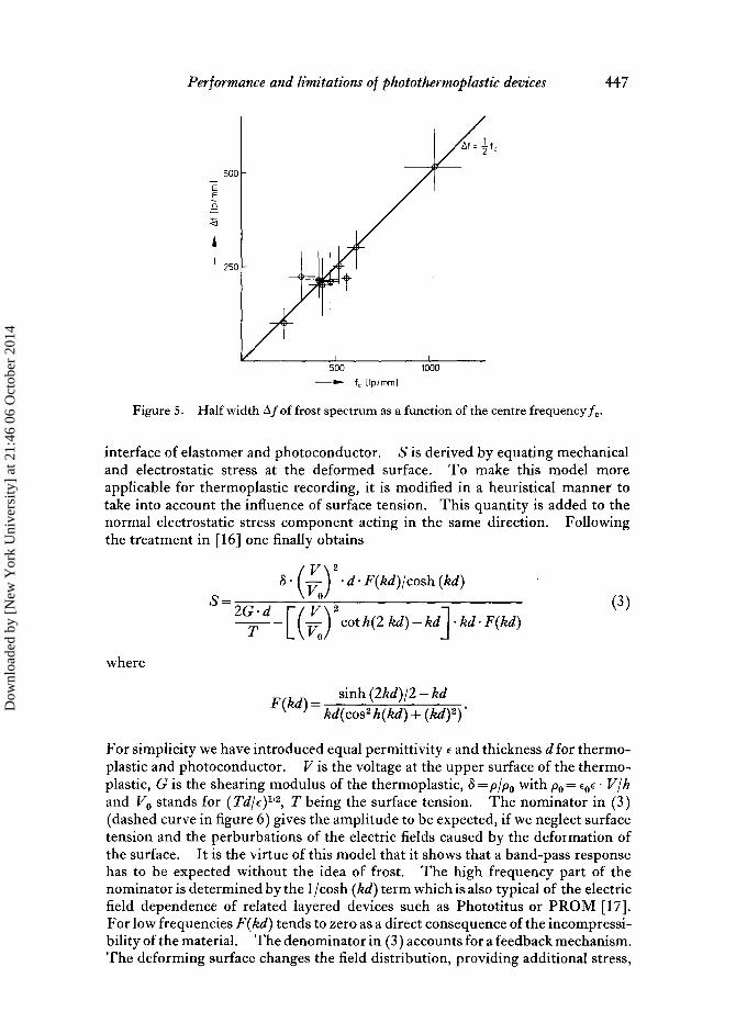
whereas it is seen from figure 5 that zf, which determines the amount of infor-mation that can be stored, is approximately given by
O f =f,/2 .
(2)
From (1) and (2) it may be concluded that information capacity can easily beincreased by decreasing d. It is, however, very difficult to achieve homogeneousthermoplastic layers for d <0 .2µm and the attainable diffraction efficiencies ford=0.2µm are lower by a factor of 10 compared to an ideal thin hologram, if oneallows modulation depths up to 40 per cent .
Theoretical analysis of the frost phenomenon has treated it as a hydrodynamicproblem in which surface tension and electrostatic forces oppose one another andlead to instability of the surface [13-15] . A relationship between frost andimage formation could not be established using this model . As thermoplasticsare viscoelastic substances they can alternatively be treated by an elastic model .Moreover, Kermisch [16] has recently developed a theory of image formation inelastomeric devices, in which the amplitude S of a surface deformation S cos (kx)
can be calculated from the corresponding charge pattern p(1 - cos (kx)) at the
1000
EEa
500
1000 .1
-~ d [pml
Figure 4 . Centre frequencyff of frost spectrum as a function of the thermoplastic's thick-ness d . Full circles : average from six identical samples, open circles : older singlemeasurements.
Dow
nloa
ded
by [
New
Yor
k U
nive
rsity
] at
21:
46 0
6 O
ctob
er 2
014
Performance and limitations o f photothermoplastic devices
447
_ 500
EEa
d
A
500f, Pp/mm]
1000
Figure 5 . Half width zXf of frost spectrum as a function of the centre frequency f . .
interface of elastomer and photoconductor . S is derived by equating mechanicaland electrostatic stress at the deformed surface . To make this model moreapplicable for thermoplastic recording, it is modified in a heuristical manner totake into account the influence of surface tension . This quantity is added to thenormal electrostatic stress component acting in the same direction . Followingthe treatment in [16] one finally obtains
S
S • (VV0
2
• d • F(kd)/cosh (kd)
2G •d
Vl 2
7,- C(V/
cot h(2 kd)-kd] •kd •F(kd)-o
where
F(kd) =kd(
sinh
osh(kd) + (kd) 2)'
(3)
For simplicity we have introduced equal permittivity a and thickness d for thermo-plastic and photoconductor . V is the voltage at the upper surface of the thermo-plastic, G is the shearing modulus of the thermoplastic, S = p/po with po= Eoc • V/hand Vo stands for (Td/E)1i2, T being the surface tension . The nominator in (3)(dashed curve in figure 6) gives the amplitude to be expected, if we neglect surfacetension and the perburbations of the electric fields caused by the deformation ofthe surface . It is the virtue of this model that it shows that a band-pass responsehas to be expected without the idea of frost . The high frequency part of thenominator is determined by the 1 /cosh (kd) term which is also typical of the electricfield dependence of related layered devices such as Phototitus or PROM [17] .For low frequencies F(kd) tends to zero as a direct consequence of the incompressi-bility of the material . The denominator in (3) accounts for a feedback mechanism .The deforming surface changes the field distribution, providing additional stress,
Dow
nloa
ded
by [
New
Yor
k U
nive
rsity
] at
21:
46 0
6 O
ctob
er 2
014
448
0-02
001
U. Killat and D. R. Terrell
/ I
_d=10um
~ d =O .S%
, .0m
\ -d=0.2pm
N
kd
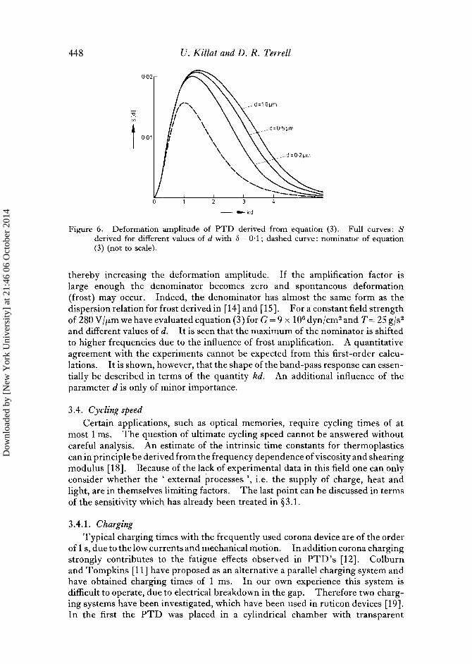
Figure 6 . Deformation amplitude of PTD derived from equation (3) . Full curves : Sderived for different values of d with S =0-1 ; dashed curve : nominator of equation(3) (not to scale) .
thereby increasing the deformation amplitude . If the amplification factor islarge enough the denominator becomes zero and spontaneous deformation(frost) may occur . Indeed, the denominator has almost the same form as thedispersion relation for frost derived in [14] and [15] . For a constant field strengthof 280 V jµm we have evaluated equation (3) for G = 9 x 10 6 dyn/cm2 and T = 25 g/s2and different values of d. It is seen that the maximum of the nominator is shiftedto higher frequencies due to the influence of frost amplification. A quantitativeagreement with the experiments cannot be expected from this first-order calcu-lations . It is shown, however, that the shape of the band-pass response can essen-tially be described in terms of the quantity kd. An additional influence of theparameter d is only of minor importance .
3.4. Cycling speedCertain applications, such as optical memories, require cycling times of at
most 1 ms . The question of ultimate cycling speed cannot be answered withoutcareful analysis . An estimate of the intrinsic time constants for thermoplasticscan in principle be derived from the frequency dependence of viscosity and shearingmodulus [18] . Because of the lack of experimental data in this field one can onlyconsider whether the ' external processes ', i .e. the supply of charge, heat andlight, are in themselves limiting factors . The last point can be discussed in termsof the sensitivity which has already been treated in § 3 .1 .
3.4.1 . ChargingTypical charging times with the frequently used corona device are of the order
of Is, due to the low currents and mechanical motion . In addition corona chargingstrongly contributes to the fatigue effects observed in PTD's [12] . Colburnand Tompkins [11] have proposed as an alternative a parallel charging system andhave obtained charging times of 1 ms . In our own experience this system isdifficult to operate, due to electrical breakdown in the gap . Therefore two charg-ing systems have been investigated, which have been used in ruticon devices [19] .In the first the PTD was placed in a cylindrical chamber with transparent
Dow
nloa
ded
by [
New
Yor
k U
nive
rsity
] at
21:
46 0
6 O
ctob
er 2
014
150
50
U
.
5
10 .5
Performance and limitations o f photothermoplastic devices
449
windows filled with an inert gas . One window was coated with a transparentelectrode and a glow discharge was produced in the gap between this electrode and
an additional ring electrode . The resulting ions were drawn from the dischargeonto the surface of the PTD by applying an appropriate bias voltage to the PTD .
Charging times of 10 ms for 1 cm 2 samples could be obtained with this system andunlike the parallel charging system no critical component alignment was neces-
sary . However, some damage to the thermoplastic due to sputtering effects
was observed .The second system investigated was accomplished by the evaporation of a thin
metal film electrode onto the upper surface of the thermoplastic . This system
suffered from contacting problems to the new electrode . However, we haverecently succeeded in storing two-beam interference patterns in a PTD with top
electrode. The diffraction efficiency was rather poor, 0 . 5 o at 800 lp/mm, but
further improvements can be expected .From our preliminary investigations it is still unclear which, if either, of these
systems will provide the rapid charging required .
3.4.2. Heat development and erasure
Heating of the thermoplastic is most effectively done by resistive heating of thetransparent electrode. The question of whether the surface of the thermoplastic
can be heated rapidly has been tackled using a one-dimensional model. The
device is simplified to a layer of thickness D = 1 ttm on a substrate of infinite extent .
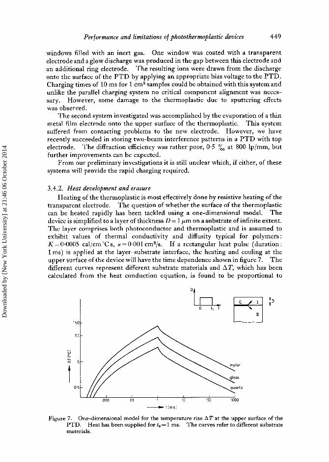
The layer comprises both photoconductor and thermoplastic and is assumed toexhibit values of thermal conductivity and diffusity typical for polymersK=0.0005 cal/cm °C s, K=0 .001 cm2/s . If a rectangular heat pulse (duration1 ms) is applied at the layer-substrate interface, the heating and cooling at theupper surface of the device will have the time dependence shown in figure 7 . Thedifferent curves represent different substrate materials and AT, which has beencalculated from the heat conduction equation, is found to be proportional to
0'
a\
I =D
Figure 7 . One-dimensional model for the temperature rise AT at the upper surface of thePTD . Heat has been supplied for t o =1 ms . The curves refer to different substratematerials .
Dow
nloa
ded
by [
New
Yor
k U
nive
rsity
] at
21:
46 0
6 O
ctob
er 2
014

450
U. Killat and D. R. Terrell
start0 heat pulse
stop
Figure 8 . Heat control for PTD (see text) .
the heat power Q. A value for Q of 200 watt/cm2 is used in figure 7 and is foundto be appropriate to thermoplastics with softening temperatures of ca . 70°C,such as Staybelite Ester 10. Glass is a satisfactory substrate material, but Mylarsubstrates should be superior judging from their higher figure of merit -,/K/K .
The most important consequence of figure 7 concerns heat dissipation, foralthough the heating process may be rapid enough, cooling to the starting tempera-ture will take too long for rapid cycling due to the well-known tilt-dependence [ 20] .
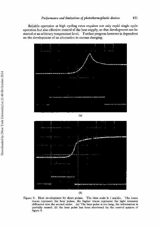
Therefore a means of starting a cycle from any temperature below the softeningpoint with a feedback mechanism controlling the critical heat dosage is required .Such a system is shown in figure 8 and operates by monitoring the second-orderdiffracted signal of the PTD during the development process . This signal isused to halt the heating process, when a certain value of the signal (or its derivative)is attained . The development of the PTD finishes almost immediately after theheating pulse ends, due to the sharp negative slope shown in all curves of figure 7after 1 ms . An experimental result is given in figure 9. Figure 9 (a) shows anexample in which the heating pulse was too long, the signal being already partiallyerased . In figure 9 (b) the heating signal was stopped after 2 .8 ms when a dif-fraction efficiency of 3 per cent was achieved. In recent experiments developmenttimes as short as 250µs have been obtained .
4 . ConclusionsPhotothermoplastic devices have considerable potential for many applications .
Some care must be taken, however, in using the most attractive figures of meritfor system design .
PTD 's in their operation (in addition to the phase character of the holograms)are inherently non-linear and therefore can only be satisfactorily used at diffractionefficiencies well below 10 per cent, depending on the system parameters .
Thermoplastic deformation is caused by electric stress which changes withchanging field upon deformation. This change has the character of a positivefeedback and leads to a greater bandwidth than expected from static resolutionconsiderations . The bandwidth is inversely proportional to the thermoplastic'sthickness . But at high resolution one has to sacrifice some diffraction efficiencydue to the small phase changes obtained with very thin layers .
Dow
nloa
ded
by [
New
Yor
k U
nive
rsity
] at
21:
46 0
6 O
ctob
er 2
014
Performance and limitations o f photothermoplastic devices
451
Reliable operation at high cycling rates requires not only rapid single cycleoperation but also effective control of the heat supply, so that development can bestarted at an arbitrary temperature level . Further progress however is dependenton the development of an alternative to corona charging .
(a)
(b)
Figure 9 . Heat development by short pulses. The time scale is 1 ms/div . The lowertraces represent the heat pulses, the higher traces represent the light intensitydiffracted into the second order . (a) The heat pulse is too long, the information ispartially erased ; (b) the heat pulse has been shortened by the control system offigure 8 .
Dow
nloa
ded
by [
New
Yor
k U
nive
rsity
] at
21:
46 0
6 O
ctob
er 2
014
452
Performance and limitations o f photothermoplastic devices
ACKNOWLEDGMENTS
The authors would like to thank G . Rabe and H. Katiofsky for their skilfulexperimental assistance .
On passe en revue les performances des thermoplastiques en cc qui concerne lasensibilite, la resolution et 1'efficacite de diffraction . On examine plus particulierement lesproblemes de linearite, la limitation de la bande passante de la fonction de transfert demodulation, et la vitesse de repetition . Sur la base d'un modele heuristique, on discutequalitativement la relation entre le signal et le gelee (frost) .
Les inconvenients du systeme resident dans la compliquee et lente operation corona etle dosage critique pour le developpement a la chaleur . On presente quelques ameliorationsrecentes dans ce domain .
Es wird die Wirkungsweise von Photothermoplasten unter Berilcksichtigung derEmpfindlichkeit, der Auflosung and dem Beugungswirkungsgrad besprochen . Dabei wirdeine besondere Aufmerksamkeit den Problemen der Linearitat, der Bandpassbegrenzungder Cbertragungsfunktion and der schnellen Zyklusgeschwindigkeit geschenkt . Auf derBasis eines heuristischen Modells wird die Beziehung zwischen Signal and dem `Frost'qualitativ diskutiert .
Engpasse des Systems liegen in der Unhandlichkeit and Langsamkeit der Korona andder kritischen Dosierung der Warmemenge, die zur Entwicklung benotigt wird . Cbereinige neue Verbesserungen zur Oberwindung dieser Engpasse wird berichtet .
REFERENCES
URBACH, J . C ., and MEIER, R. W ., 1966, Appl. Optics, 5, 666 .GRAY, P . F., and BARNETT, M . E., 1974, Opt. Commun ., 12, 275 .BELLAMY, J. C ., OSTROWSKY, D. B ., POINDRON, M ., and SPITZ, E., 1971, Appl. Optics,
10, 1458 .CREDELLE, T . L., and SPONG, F. W., 1972, RCA Rev., 33, 206 .THINH, V. N ., and TANAKA ., S., 1973, Yap . Y. appl. Phys ., 12, 1954 .LIN, L. H., and BEAUCHAMP, H . L., 1970, Appl. Optics, 9, 2088 .STEWART, W. C., MEZRICH, R . S., COSENTINO, L. S ., NAGLE, E. M., WENDT, F. S .,and LOHMAN, R. D ., 1973, RCA Rev., 34, 3 .
BUTTER, C. D., and LEE, T . C ., 1975, I.E.E.E. Trans., C-24, 402 .TERRELL, D. R., and KATIOFSKY, H ., 1977, J . appl. Polym . Sci . (to be published) .CHANG, L. S., 1968, Photogr . Sci . Engng., 12, 238 .COLBURN, W. S., and TOMPKINS, E . N., 1974, Appl. Optics, 13, 2934 .LEE, T . C., 1974, Appl. Optics., 13, 888 .CRESSMAN, P . J ., 1963, Y. appl. Phys ., 34, 2327 .BUDD, H. F., 1965, Y. appl. Phys ., 36, 1613 .KILLAT, U., 1975, Y. appl. Phys ., 46, 5169 .KERMISCH, D., 1976, Appl. Optics, 15, 1775 .ROACH, W. R., 1974, I.E.E.E. Trans ., ED-21, 453 .FERRY, J . D ., 1970, Viscoelastic Properties of Polymers, 2nd edition (J . Wiley & Sons, Inc .) .SHERIDON, N. K ., 1972, I.E.E.E. Trans ., ED-19,1003 .CARSLOW, H. S ., and JAEGER, J . C ., 1973, Conduction of Heat in Solids (Oxford Univer-sity Press) Chap . II .
Dow
nloa
ded
by [
New
Yor
k U
nive
rsity
] at
21:
46 0
6 O
ctob
er 2
014