performance analysis of cellular manufacturing … · performance analysis of cellular...
TRANSCRIPT
PERFORMANCE ANALYSIS OF
CELLULAR MANUFACTURING SYSTEMS USING COLORED PETRI NETS
Hilano José Rocha de Carvalho (USP-EESC) [email protected]
Arthur José Vieira Por to (USP-EESC) [email protected]
The need for flexibility due to the global competitiveness is influencing the way companies are organized. There are several ways of organizing a manufacturing system directly dependent on the volume and on the variability of the products ddemanded. In order to reduce material handling and production scrap costs, cellular manufacturing systems (CMS) have emerged. Concerning a CMS study, the building of simulation models capable of handling complex simultaneity of processes and multifunctional work policies motivates the use of more efficient programming and simulation techniques. Hence, the aim of this paper is focused on proposing the use of colored Petri net formalism to develop a simulation model for the analysis of cellular manufacturing systems with multifunctional workforce in order to overcome the former limitations. The CPN Tools was used for the CPN edition and simulation analysis. The resultant colored Petri net based cellular manufacturing system simulation model (CPNCMSSM) was successfully used for the practical investigation of a three-working-cell CMS. Three scenarios were studied for which the number of family parts was the factor altered, converging to adequate and expected results about multifunctional work performance and work in process magnitude. Hence, the CPNCMSSM can be used to the study of bigger and more complex arrangements as an alternative to conventional programming and simulation languages and tools available. Keywords: Colored Petri nets, Cellular Manufacturing Systems, Simulation
��������������� ������������������������� ����� ����� ��� �� �!"�� #%$'&���(�� ��&&�" � � ( #�� �)� *�&"�#�!� � �� ,+-#%��#�( &�+.&���!/1032547698�:�;9<=:%>@?9AB2DCFE94�?9G9H3IJ:LK ?909M9<@G9K <DN ?969H32O<D>P?9036QK 0R:L25694�<=:�K ?903S1E947?UT725IJ:V<W03G@CDH9CX:X<DK 03<WY9K N K :�8
Iguassu Falls, PR, Brazil, 09 - 11 October 2007
Z [\[\[][\^`_�a`b�^dc_�[�eV^dc�fPg�eV^%h1a1b�a1^%g]aPi�j.k j�l�m�n�o9p�k q�rP/1j�s�k jV/1/1p�k j�s.q�j�l.iVt]/`pVq�o9k i�j�n'uQq�j�q�s�/`uQ/1j�ovDwBxUy zX{�|�}B~�|d�����9xR�%�Dy �5���B��|�� �BwB�B~��B� ~U� �5zB�Bx�~U���BwBz � wX|�xRz5y ~�|�� �DwB�B�By\���\xU��|d~UwB���J�B��|�~U� w�~U�B� � � | {
Iguassu Falls, PR, Brazil, 09 - 11 October 2007
2
1. Introduction
The need for flexibility due to the global competitiveness is influencing the way
companies are organized. There are several ways of organizing a manufacturing system directly
dependent on the volume and on the variability of the products demanded (ASKIN, 1993). In
order to reduce material handling and production scrap costs, cellular manufacturing systems
(CMS) have emerged. As a matter of fact, such a system is defined by the concept of part family
about which different types of machines and products (or parts) are grouped according to a
predefined similarity index, e.g., the sequence of production operations, in order to form working
cells (SINGH & RAJAMANI, 2004).
Computer tools to model and simulate cellular or any kind of production system already
exist (LAW & KELTON, 2000). However, the time taken by the modeler using conventional
simulation programming languages to adapt a primary model for different scenarios may be a
costly constraint. In addition, an attempt to generalize a simulation model may yield modeling
loss of expressiveness, especially considering complex simultaneity of processes and material
handling.
Hence, the main objective of this paper is focused on the proposal of using a colored Petri
net simulation model to model and to simulate cellular manufacturing systems in order to reduce
complexity and modeling time without loss of expressiveness.
As a related work, Carvalho et al. (2005) demonstrated the potentiality of Petri nets to
model and to analyze the performance of the multifunctional workforce in a U-shaped production
line compared to other simulation languages. However, due to the low level Petri nets
limitations, especially in terms of the huge number of modeling elements, different levels of
complexity inherently present in real and large manufacturing systems demand a more
sophisticated approach. In this sense, the investigation herein tries to overcome the drawbacks
and to keep the positive aspects evidenced by Carvalho et al. (2005) using a high level Petri net
formalism.
The remainder of this paper is organized as follows. In Section 2, the theory of colored
Petri nets formalism is focused, concerning its main concepts and modeling and simulation
elements, the CPN tools for academic purposes. In Section 3, a colored Petri net based cellular
Z [\[\[][\^`_�a`b�^dc_�[�eV^dc�fPg�eV^%h1a1b�a1^%g]aPi�j.k j�l�m�n�o9p�k q�rP/1j�s�k jV/1/1p�k j�s.q�j�l.iVt]/`pVq�o9k i�j�n'uQq�j�q�s�/`uQ/1j�ovDwBxUy zX{�|�}B~�|d�����9xR�%�Dy �5���B��|�� �BwB�B~��B� ~U� �5zB�Bx�~U���BwBz � wX|�xRz5y ~�|�� �DwB�B�By\���\xU��|d~UwB���J�B��|�~U� w�~U�B� � � | {
Iguassu Falls, PR, Brazil, 09 - 11 October 2007
3
manufacturing system simulation model (CPNCMSSM) is presented. Section 4 is dedicated to
the practical use of CPNCMSSM using simulation. Finally, Section 5 is focused on the
conclusions and final considerations.
2. Colored Petr i nets
The theory of colored Petri nets (CPN) was developed as an extension to the basic Petri
nets theory (JENSEN, 1997). The prime objective of CPN is to make feasible the modeling and
formal analysis of large, concurrent and distributed systems using Petri nets. A detailed definition
and discusson about the CPN formalism can be found in Jensen (1997).
The CPN tools as defined in Jensen et al. (2007), in turn, comprise two components: a
graphical user interface (GUI) and CPN ML. These ones are directly related to three integrated
tools: the CPN editor, the CPN simulator and the CPN state space tool. The CPN ML is a
functional programming language implemented on top of a SML/NJ compiler. Herein used, the
CPN tools 2.2.0 academic version was obtained from CPNTools (2006).
Based on the CPN formalism and the CPN tools as defined above, the token primitive and
compound types are defined by the color sets associated with each place and their type
modifications are accomplished by the functions defined on the arcs. In order to do that, the
corresponding transition must be enabled to fire. This happens when the number and the type of
the input place tokens to the transition agrees with the conditions of transition’s enablement
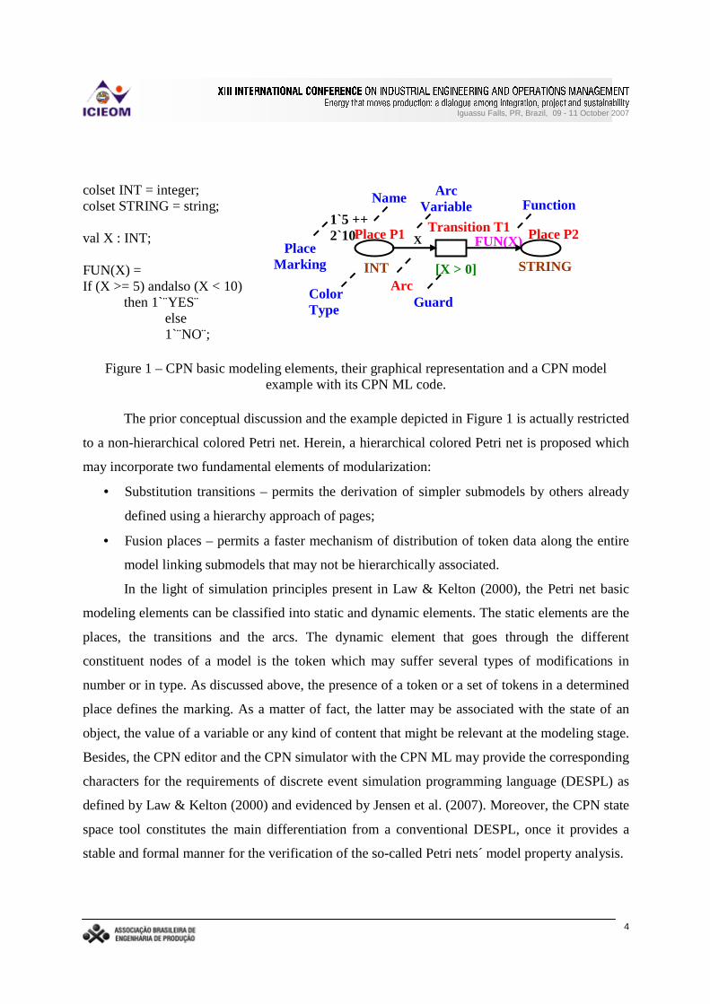
defined by the transition guard. Figure 1 shows the CPN basic modeling elements, their graphical
representation and an example of how to deal with the CPN formalism.
As can be seen in Figure 1, the initial state of the CPN model is represented by three
tokens in “Place P1” . The number and the type of those tokens are defined by the initial place
marking of P1 (in this case, a five integer token and two ten integer tokens). They are three true
firing conditions to “Transition T1” since they are in agreement with the transition guard. The
firing of T1 initialize the function “FUN(X)”. “FUN(X)” captures the token data by the arc
variable “X” and transforms them into one string token in number and in type following the “ if-
then-else” structure of the CPN ML code of Figure 1. Finally, “Place P2” receives the one string
token from “FUN(X)” .
Z [\[\[][\^`_�a`b�^dc_�[�eV^dc�fPg�eV^%h1a1b�a1^%g]aPi�j.k j�l�m�n�o9p�k q�rP/1j�s�k jV/1/1p�k j�s.q�j�l.iVt]/`pVq�o9k i�j�n'uQq�j�q�s�/`uQ/1j�ovDwBxUy zX{�|�}B~�|d�����9xR�%�Dy �5���B��|�� �BwB�B~��B� ~U� �5zB�Bx�~U���BwBz � wX|�xRz5y ~�|�� �DwB�B�By\���\xU��|d~UwB���J�B��|�~U� w�~U�B� � � | {
Iguassu Falls, PR, Brazil, 09 - 11 October 2007
4
colset INT = integer; colset STRING = string; val X : INT; FUN(X) = If (X >= 5) andalso (X < 10)
then 1`¨YES else 1`¨NO¨;
Figure 1 – CPN basic modeling elements, their graphical representation and a CPN model example with its CPN ML code.
The prior conceptual discussion and the example depicted in Figure 1 is actually restricted
to a non-hierarchical colored Petri net. Herein, a hierarchical colored Petri net is proposed which
may incorporate two fundamental elements of modularization:
• Substitution transitions – permits the derivation of simpler submodels by others already
defined using a hierarchy approach of pages;
• Fusion places – permits a faster mechanism of distribution of token data along the entire
model linking submodels that may not be hierarchically associated.
In the light of simulation principles present in Law & Kelton (2000), the Petri net basic
modeling elements can be classified into static and dynamic elements. The static elements are the
places, the transitions and the arcs. The dynamic element that goes through the different
constituent nodes of a model is the token which may suffer several types of modifications in
number or in type. As discussed above, the presence of a token or a set of tokens in a determined
place defines the marking. As a matter of fact, the latter may be associated with the state of an
object, the value of a variable or any kind of content that might be relevant at the modeling stage.
Besides, the CPN editor and the CPN simulator with the CPN ML may provide the corresponding
characters for the requirements of discrete event simulation programming language (DESPL) as
defined by Law & Kelton (2000) and evidenced by Jensen et al. (2007). Moreover, the CPN state
space tool constitutes the main differentiation from a conventional DESPL, once it provides a
stable and formal manner for the verification of the so-called Petri nets model property analysis.
FUN(X)
INT STRING
X
1`5 ++ 2`10
[X > 0]
Color Type
Place P1 Place
Marking
Arc Var iable
Transition T1
Function
Arc Guard
Place P2
Name
Z [\[\[][\^`_�a`b�^dc_�[�eV^dc�fPg�eV^%h1a1b�a1^%g]aPi�j.k j�l�m�n�o9p�k q�rP/1j�s�k jV/1/1p�k j�s.q�j�l.iVt]/`pVq�o9k i�j�n'uQq�j�q�s�/`uQ/1j�ovDwBxUy zX{�|�}B~�|d�����9xR�%�Dy �5���B��|�� �BwB�B~��B� ~U� �5zB�Bx�~U���BwBz � wX|�xRz5y ~�|�� �DwB�B�By\���\xU��|d~UwB���J�B��|�~U� w�~U�B� � � | {
Iguassu Falls, PR, Brazil, 09 - 11 October 2007
5
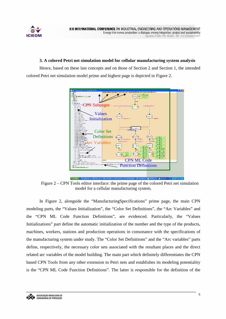
3. A colored Petr i net simulation model for cellular manufactur ing system analysis
Hence, based on these last concepts and on those of Section 2 and Section 1, the intended
colored Petri net simulation model prime and highest page is depicted in Figure 2.
Figure 2 – CPN Tools editor interface: the prime page of the colored Petri net simulation model for a cellular manufacturing system.
In Figure 2, alongside the “ManufacturingSpecifications” prime page, the main CPN
modeling parts, the “Values Initialization” , the “Color Set Definitions” , the “Arc Variables” and
the “CPN ML Code Function Definitions” , are evidenced. Particularly, the “Values
Initializations” part define the automatic initialization of the number and the type of the products,
machines, workers, stations and production operations in consonance with the specifications of
the manufacturing system under study. The “Color Set Definitions” and the “Arc variables” parts
define, respectively, the necessary color sets associated with the resultant places and the direct
related arc variables of the model building. The main part which definitely differentiates the CPN
based CPN Tools from any other extension to Petri nets and establishes its modeling potentiality
is the “CPN ML Code Function Definitions” . The latter is responsible for the definition of the
Values Initialization
Color Set Definitions
Arc Variables
CPN ML Code Function Definitions
CPN Subpages
Z [\[\[][\^`_�a`b�^dc_�[�eV^dc�fPg�eV^%h1a1b�a1^%g]aPi�j.k j�l�m�n�o9p�k q�rP/1j�s�k jV/1/1p�k j�s.q�j�l.iVt]/`pVq�o9k i�j�n'uQq�j�q�s�/`uQ/1j�ovDwBxUy zX{�|�}B~�|d�����9xR�%�Dy �5���B��|�� �BwB�B~��B� ~U� �5zB�Bx�~U���BwBz � wX|�xRz5y ~�|�� �DwB�B�By\���\xU��|d~UwB���J�B��|�~U� w�~U�B� � � | {
Iguassu Falls, PR, Brazil, 09 - 11 October 2007
6
methods defined by the manufacturing system processes which will act directly on the token
modifications in number and in type.
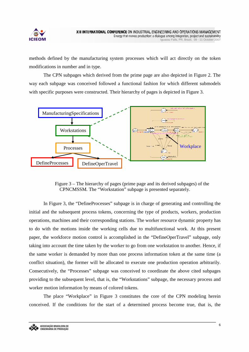
The CPN subpages which derived from the prime page are also depicted in Figure 2. The
way each subpage was conceived followed a functional fashion for which different submodels
with specific purposes were constructed. Their hierarchy of pages is depicted in Figure 3.
Figure 3 – The hierarchy of pages (prime page and its derived subpages) of the CPNCMSSM. The “Workstation” subpage is presented separately.
In Figure 3, the “DefineProcesses” subpage is in charge of generating and controlling the
initial and the subsequent process tokens, concerning the type of products, workers, production
operations, machines and their corresponding stations. The worker resource dynamic property has
to do with the motions inside the working cells due to multifunctional work. At this present
paper, the workforce motion control is accomplished in the “DefineOperTravel” subpage, only
taking into account the time taken by the worker to go from one workstation to another. Hence, if
the same worker is demanded by more than one process information token at the same time (a
conflict situation), the former will be allocated to execute one production operation arbitrarily.
Consecutively, the “Processes” subpage was conceived to coordinate the above cited subpages
providing to the subsequent level, that is, the “Workstations” subpage, the necessary process and
worker motion information by means of colored tokens.
The place “Workplace” in Figure 3 constitutes the core of the CPN modeling herein
conceived. If the conditions for the start of a determined process become true, that is, the
ManufacturingSpecifications
Workstations
DefineProcesses DefineOperTravel
Processes Workplace
Z [\[\[][\^`_�a`b�^dc_�[�eV^dc�fPg�eV^%h1a1b�a1^%g]aPi�j.k j�l�m�n�o9p�k q�rP/1j�s�k jV/1/1p�k j�s.q�j�l.iVt]/`pVq�o9k i�j�n'uQq�j�q�s�/`uQ/1j�ovDwBxUy zX{�|�}B~�|d�����9xR�%�Dy �5���B��|�� �BwB�B~��B� ~U� �5zB�Bx�~U���BwBz � wX|�xRz5y ~�|�� �DwB�B�By\���\xU��|d~UwB���J�B��|�~U� w�~U�B� � � | {
Iguassu Falls, PR, Brazil, 09 - 11 October 2007
7
resources tokens demanded by the process information tokens are all simultaneously available, a
job token with a time stamp corresponding to the process time (based on the type of the
operation, product and machine) is put into the place “Workplace” . In this sense, the
simultaneous presence of different job tokens in place “Workplace” represents a condensed form
of modeling the simultaneity of several workstations carrying out different production operations
which correspond to the wholly function of the entire cellular manufacturing system.
4. A practical use of CPNCMSSM with simulation results
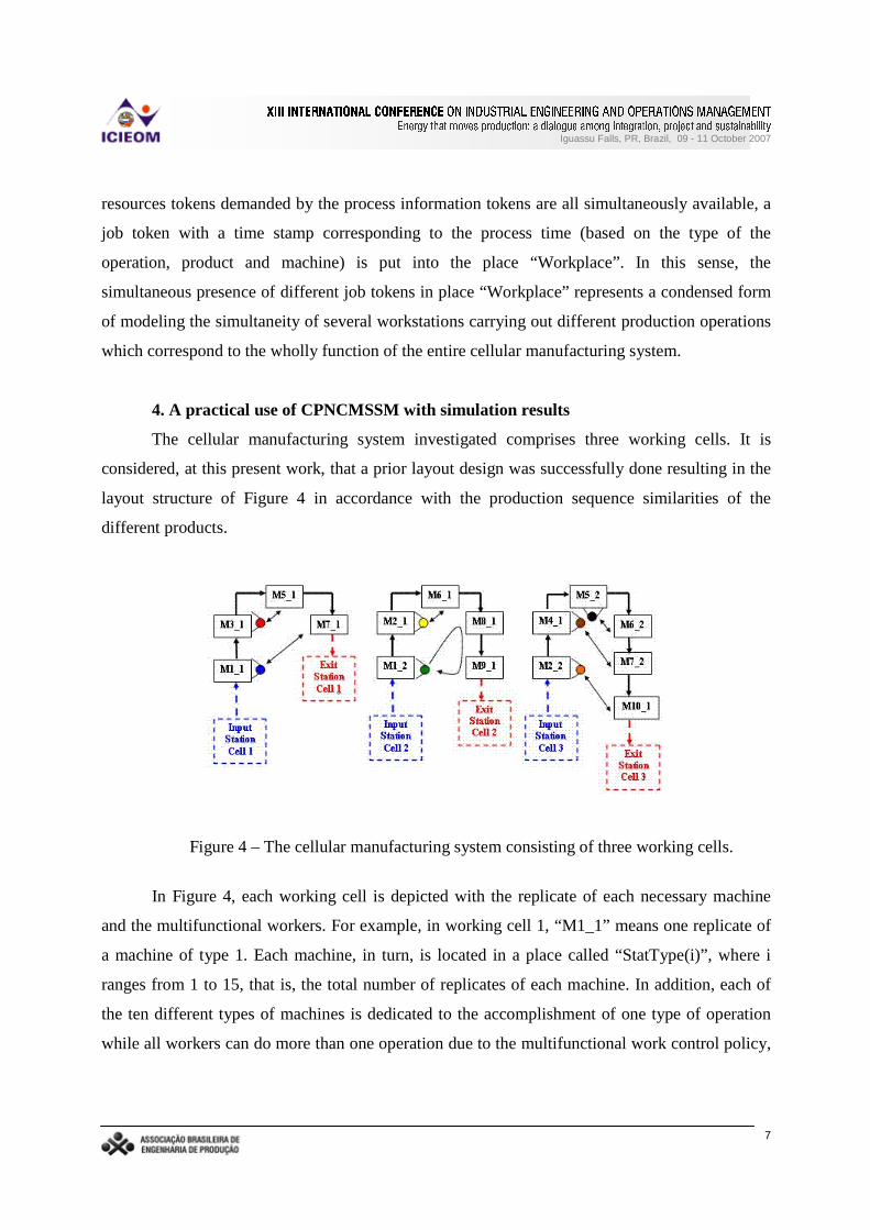
The cellular manufacturing system investigated comprises three working cells. It is
considered, at this present work, that a prior layout design was successfully done resulting in the
layout structure of Figure 4 in accordance with the production sequence similarities of the
different products.
Figure 4 – The cellular manufacturing system consisting of three working cells.
In Figure 4, each working cell is depicted with the replicate of each necessary machine
and the multifunctional workers. For example, in working cell 1, “M1_1” means one replicate of
a machine of type 1. Each machine, in turn, is located in a place called “StatType(i)” , where i
ranges from 1 to 15, that is, the total number of replicates of each machine. In addition, each of
the ten different types of machines is dedicated to the accomplishment of one type of operation
while all workers can do more than one operation due to the multifunctional work control policy,
Z [\[\[][\^`_�a`b�^dc_�[�eV^dc�fPg�eV^%h1a1b�a1^%g]aPi�j.k j�l�m�n�o9p�k q�rP/1j�s�k jV/1/1p�k j�s.q�j�l.iVt]/`pVq�o9k i�j�n'uQq�j�q�s�/`uQ/1j�ovDwBxUy zX{�|�}B~�|d�����9xR�%�Dy �5���B��|�� �BwB�B~��B� ~U� �5zB�Bx�~U���BwBz � wX|�xRz5y ~�|�� �DwB�B�By\���\xU��|d~UwB���J�B��|�~U� w�~U�B� � � | {
Iguassu Falls, PR, Brazil, 09 - 11 October 2007
8
as evidenced in Figure 4. Hence, the CPNCMSSM as defined in Section 3 was adapted to the
CMS of Figure 4. The distance among the fifteen machine replicates were approximately
considered in order to calculate the delay times associated with the multifunctional workforce
motion. The different process times of each machine were also taken into account. For the
generation of all types of initial process information tokens, an exponential distribution with
average rate of 100 was defined. Concerning this, for the maximum statistical confidence of
analysis, twenty replications of 48000 steps each were considered for the three scenarios
analyzed. These three different scenarios were defined varying the number of products: six
products for the first one, twelve products for the second one and eighteen products for the last
one. In this sense, the main objective of the experimental investigation herein is simply to verify
the use of CPNCMSSM on the performance analysis of the multifunctional workforce due to the
increase of the number of family parts.
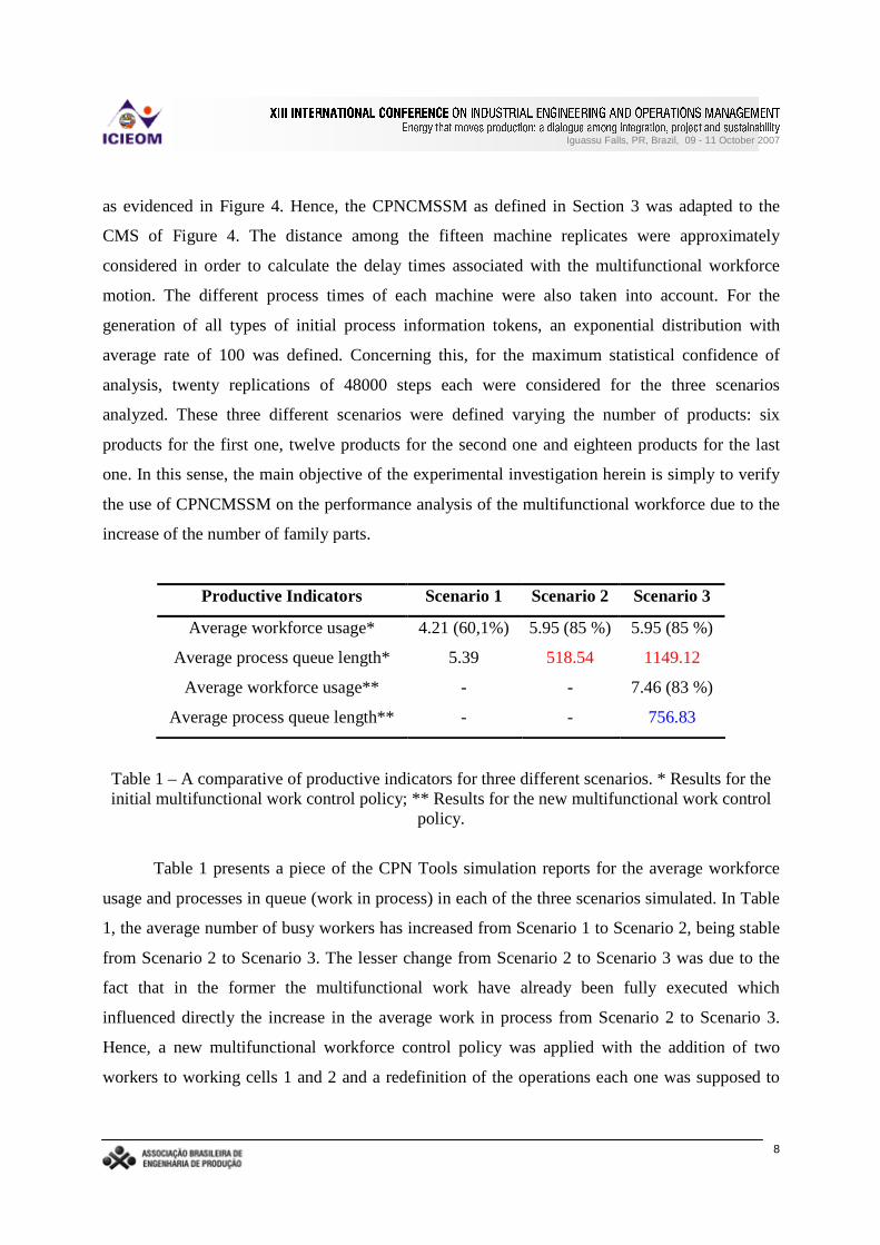
Productive Indicators Scenar io 1 Scenar io 2 Scenar io 3
Average workforce usage* 4.21 (60,1%) 5.95 (85 %) 5.95 (85 %)
Average process queue length* 5.39 518.54 1149.12
Average workforce usage** - - 7.46 (83 %)
Average process queue length** - - 756.83
Table 1 – A comparative of productive indicators for three different scenarios. * Results for the initial multifunctional work control policy; * * Results for the new multifunctional work control
policy.
Table 1 presents a piece of the CPN Tools simulation reports for the average workforce
usage and processes in queue (work in process) in each of the three scenarios simulated. In Table
1, the average number of busy workers has increased from Scenario 1 to Scenario 2, being stable
from Scenario 2 to Scenario 3. The lesser change from Scenario 2 to Scenario 3 was due to the
fact that in the former the multifunctional work have already been fully executed which
influenced directly the increase in the average work in process from Scenario 2 to Scenario 3.
Hence, a new multifunctional workforce control policy was applied with the addition of two
workers to working cells 1 and 2 and a redefinition of the operations each one was supposed to

Z [\[\[][\^`_�a`b�^dc_�[�eV^dc�fPg�eV^%h1a1b�a1^%g]aPi�j.k j�l�m�n�o9p�k q�rP/1j�s�k jV/1/1p�k j�s.q�j�l.iVt]/`pVq�o9k i�j�n'uQq�j�q�s�/`uQ/1j�ovDwBxUy zX{�|�}B~�|d�����9xR�%�Dy �5���B��|�� �BwB�B~��B� ~U� �5zB�Bx�~U���BwBz � wX|�xRz5y ~�|�� �DwB�B�By\���\xU��|d~UwB���J�B��|�~U� w�~U�B� � � | {
Iguassu Falls, PR, Brazil, 09 - 11 October 2007
9
perform. Due to the latter modifications, as can be seen in Table 1, the average work in process
has considerably decreased for Scenario 3, but the average workforce usage remained
approximately the same from the one obtained by the former multifunctional work control policy
in percentage terms.
5. Conclusions
The performance analysis of multifunctional work in manufacturing system using Petri
nets was already evidenced by Carvalho et al. (2005). However, only by means of a CPN model
and CPN Tools, an effective cellular manufacturing system can be analyzed, as demonstrated by
a practical case in Section 4. The resultant colored Petri net based cellular manufacturing system
simulation model (CPNCMSSM) of Section 3 is general enough to be used to any kind of CMS,
since the modeler has only the task to change the possible machine distance alterations due to
layout re-designs and to consider or not multifunctional workforce. Even the addition of new
productive resources, such as workers and machines, can be easily done. Without a doubt,
CPNCMSSM is an alternative technique from conventional simulation languages and packages,
especially owing to multifunctional work and process simultaneity modeling power. For further
works, a user-friendly interface and an automatic code generator (CPNCMSSM´s CPN ML)
could be implemented by means of CPN Tools external communication with other programming
techniques.
References
ASKIN, R.G. & STANDRIDGE, C.R. Modeling and Analysis of Manufacturing Systems. New York: John Wiley & Sons, 1993.
CARVALHO, H. J. R. & YOSHIZAWA, A. R. & PONTES, H. L. J., & PORTO, A. J. V. Modelagem e Simulação de Linhas de Produção em Forma de U com Operadores Polivalentes por Redes de Petri Temporizadas, Anais do XXV Encontro Nacional de Engenharia de Produção, 2005.
CPNTools. Available via <http://wiki.daimi.au.dk/cpntools/cpntools.wiki> accessed in November, 2006.
DESROCHERS, A. & AL-JAAR, R. Applications of Petri Nets in Manufacturing Systems: modeling, control, and performance analysis, New York: IEEE Press, 1995.
JENSEN, K. Colored Petri Nets: Basic Concepts. 2. ed. New York: Springer, 1997.
JENSEN, K. & KRISTENSEN, L.R. & WELLS, L. Coloured Petri Nets and CPN Tools for Modeling and Validation of Concurrent Systems. International Journal on Software Tools for Technology Transfer. Special Section CPN 04/05, p.1-42, 2007.
LAW, A.M., & KELTON, W.D. Simulation modeling & analysis. 3. ed. New York: McGraw Hill

Z [\[\[][\^`_�a`b�^dc_�[�eV^dc�fPg�eV^%h1a1b�a1^%g]aPi�j.k j�l�m�n�o9p�k q�rP/1j�s�k jV/1/1p�k j�s.q�j�l.iVt]/`pVq�o9k i�j�n'uQq�j�q�s�/`uQ/1j�ovDwBxUy zX{�|�}B~�|d�����9xR�%�Dy �5���B��|�� �BwB�B~��B� ~U� �5zB�Bx�~U���BwBz � wX|�xRz5y ~�|�� �DwB�B�By\���\xU��|d~UwB���J�B��|�~U� w�~U�B� � � | {
Iguassu Falls, PR, Brazil, 09 - 11 October 2007
10
Inc., 2000.
SINGH, N. & RAJAMANI, D. Cellular Manufacturing Systems: Design, Planning and Control. Chapman & Hall: John Wiley & Sons, 1993.