“perfect fit” in-dash · pdf file1 “perfect fit” in-dash heat/ cool/...
TRANSCRIPT
1
“PERFECT FIT”
IN-DASH HEAT/ COOL/ DEFROST
1967-72 CHEVROLET PICKUP
CONTROL & OPERATING INSTRUCTIONS
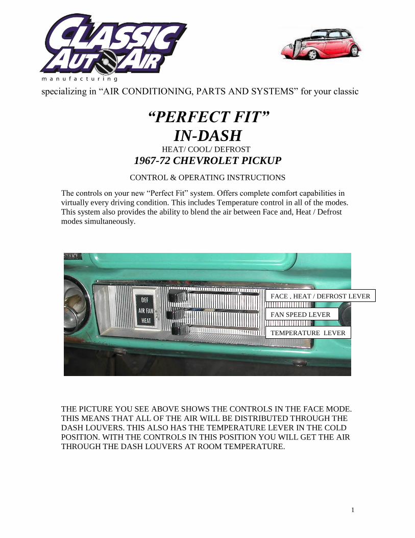
The controls on your new “Perfect Fit” system. Offers complete comfort capabilities in
virtually every driving condition. This includes Temperature control in all of the modes.
This system also provides the ability to blend the air between Face and, Heat / Defrost
modes simultaneously.
THE PICTURE YOU SEE ABOVE SHOWS THE CONTROLS IN THE FACE MODE.
THIS MEANS THAT ALL OF THE AIR WILL BE DISTRIBUTED THROUGH THE
DASH LOUVERS. THIS ALSO HAS THE TEMPERATURE LEVER IN THE COLD
POSITION. WITH THE CONTROLS IN THIS POSITION YOU WILL GET THE AIR
THROUGH THE DASH LOUVERS AT ROOM TEMPERATURE.
TEMPERATURE LEVER
FAN SPEED LEVER
FACE , HEAT / DEFROST LEVER
specializing in “AIR CONDITIONING, PARTS AND SYSTEMS” for your classic
vehicle
2
CAUTION: ALL OF THE OUTSIDE VENTS MUST BE CLOSED WHEN THE
SYSTEM IS IN THE A/C MODE. THIS WILL ALLOW THE A/C SYSTEM TO
FUCTION AT ITS MAXIMUM PERFORMANCE LEVEL.
THE FOLLOWING SUMMARY WILL DESCRIBE EACH OF THE CONTROL
LEVERS FUNCTION.
FAN SPEED LEVER: There are 3 speeds plus Off. When the switch is in the off
position it will disconnect the 12V power to the Blower Motor and the A/C Clutch. This
will shut down the entire system. When the switch is moved to any of the blower speeds
1,2 or 3 there is 12V supplied to the Micro-Switch which is mounted on the main
housing.
FACE / HEAT, DEFROST LEVER: The lever as shown in the picture is in the
Face position. The lever all the way to the left will engage the compressor for air
conditioning mode. As this lever is moved towards the right, the clutch will disengage
and it will change the air from the Face louvers and blend into the Heat / Defrost outlets.
Only when the lever is in the far right position will the compressor engage and provide
“Dehumidified” defrost.
TEMPERATURE CONTROL: The temperature lever as shown is in the
COLDEST temperature position. As the lever is pushed to the right the temperature of
the discharged air will rise to the HOTTEST point.
Note: The temperature lever will function in any of the modes.
AIR CONDITIONING MODE: The picture shows the controls in the Face Mode
(air-flow out the dash louvers).
When Air Conditioning is required the compressor clutch must be activated. This is
accomplished by pushing the lever all the way to the LEFT. When the compressor is
activated the Temperature Lever will control the air from maximum cold through
maximum heat.
3
INSTALLATION INSTRUCTIONS
1967-72 CHEVROLET PICKUP
Congratulations! ! You have just purchased the highest quality, best performing A/C system
ever designed for you Classic Car. To obtain the high level of performance and dependability
our systems are known for, pay close attention to the following instructions.
Before beginning the installation check the box for the correct components.
Evaporator
Face Duct Assembly
Inlet Air Block Off Assembly
Firewall Block Off Assembly
Flex Hose 2”dia. x 3ft.
Flex Hose 2”dia. x 4ft x 2ea..
Flex Hose 2 ½”dia. x 2 ft.
Sack Kit Louver
Sack Kit Hardware
Sack Kit Control
Glove Box
IMPORTANT INFORMATION
1. Before starting, read the instructions carefully and follow proper sequence.
2. Check condition of engine mounts. Excessive engine movement can damage
hoses to A/C, heater, radiator, transcooler, and power steering systems.
3. Before starting, check vehicle interior electrical functions. i.e. interior lights,
radio, horn, etc. When ready to start installation, disconnect battery.
4. Fittings. Use one or two drops of lubricant on O’rings, threads and rear of bump
for O’ring where female nut rides. Do not use thread tape or sealants.
5. Always use two wrenches to tighten fittings. Try holding in one hand while
squeezing together while other hand holds fitting in position.
6. Shaft seals in a small percentage of compressors will require as much as 3-4
hours run time to become leak free.
7. Compressors supplied in our complete systems are filled with proper amount of
oil.
8. Compressor requires technician to hand turn 15-20 revolutions before and after
charging with liquid from a charging station before running system.
Compressors with damaged reed valves cannot be warranted.
9. Should you have any technical questions, or are suspect of missing, or defective
parts, call us immediately. Our knowledgeable staff will be glad to assist you.
specializing in “AIR CONDITIONING, PARTS AND SYSTEMS” for your classic
vehicle
4
YOU CAN NOW BEGIN THE INSTALLATION
CAUTION: DISCONNECT BATTERY GROUND CABLE
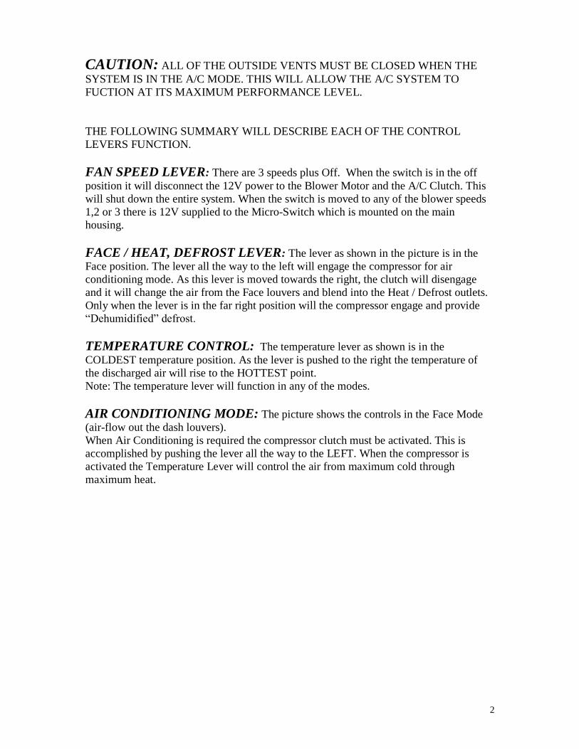
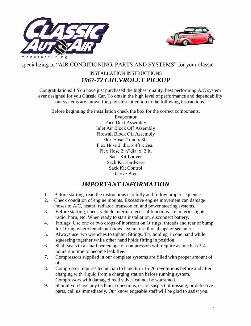
Remove Glove box, Heater
controls and Radio, set aside for
reinstall.
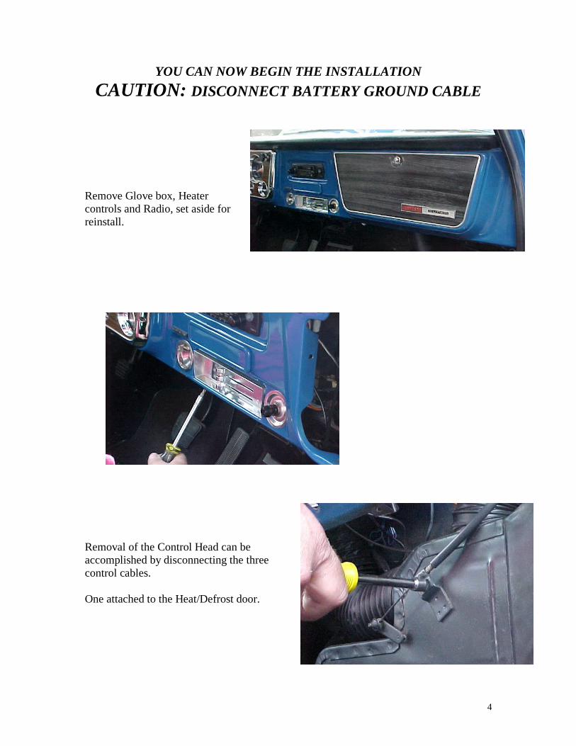
Removal of the Control Head can be
accomplished by disconnecting the three
control cables.
One attached to the Heat/Defrost door.
5
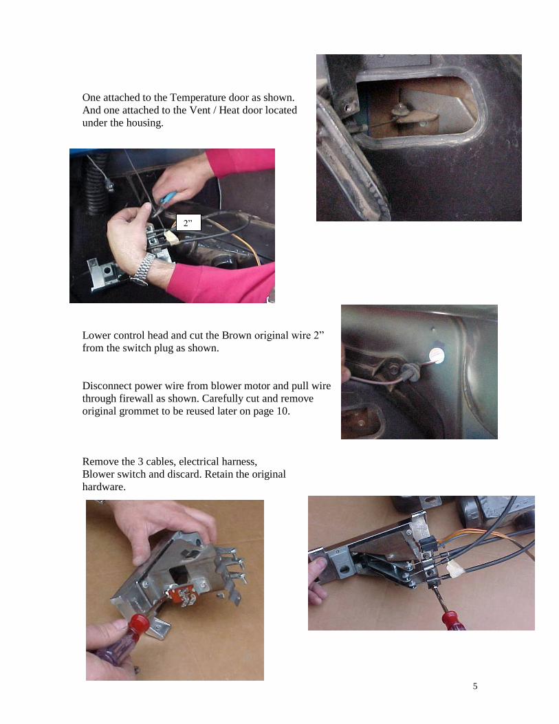
One attached to the Temperature door as shown.
And one attached to the Vent / Heat door located
under the housing.
Lower control head and cut the Brown original wire 2”
from the switch plug as shown.
Disconnect power wire from blower motor and pull wire
through firewall as shown. Carefully cut and remove
original grommet to be reused later on page 10.
Remove the 3 cables, electrical harness,
Blower switch and discard. Retain the original
hardware.
2”
6
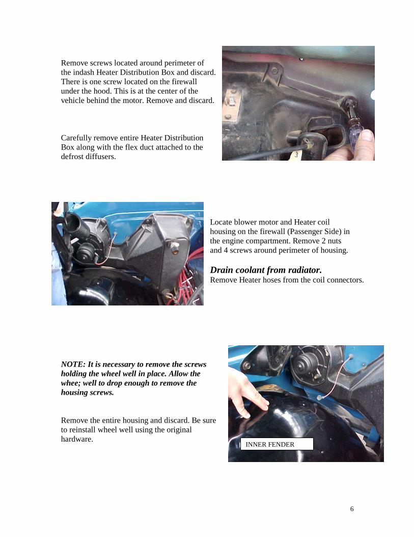
Remove screws located around perimeter of
the indash Heater Distribution Box and discard.
There is one screw located on the firewall
under the hood. This is at the center of the
vehicle behind the motor. Remove and discard.
Carefully remove entire Heater Distribution
Box along with the flex duct attached to the
defrost diffusers.
Locate blower motor and Heater coil
housing on the firewall (Passenger Side) in
the engine compartment. Remove 2 nuts
and 4 screws around perimeter of housing.
Drain coolant from radiator. Remove Heater hoses from the coil connectors.
NOTE: It is necessary to remove the screws
holding the wheel well in place. Allow the
whee; well to drop enough to remove the
housing screws.
Remove the entire housing and discard. Be sure
to reinstall wheel well using the original
hardware.
INNER FENDER
7
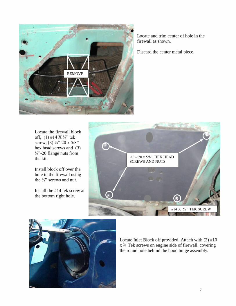
Locate and trim center of hole in the
firewall as shown.
Discard the center metal piece.
Locate the firewall block
off, (1) #14 X ¾” tek
screw, (3) ¼”-20 x 5/8”
hex head screws and (3)
¼”-20 flange nuts from
the kit.
Install block off over the
hole in the firewall using
the ¼” screws and nut.
Install the #14 tek screw at
the bottom right hole.
Locate Inlet Block off provided. Attach with (2) #10
x ¾ Tek screws on engine side of firewall, covering
the round hole behind the hood hinge assembly.
REMOVE
¼” – 20 x 5/8” HEX HEAD
SCREWS AND NUTS
#14 X ¾” TEK SCREW
8
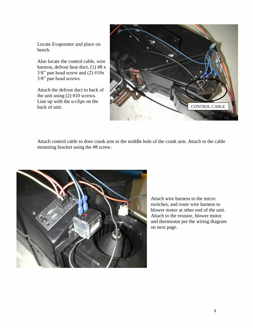
Locate Evaporator and place on
bench.
Also locate the control cable, wire
harness, defrost heat duct, (1) #8 x
3/8” pan head screw and (2) #10x
5/8” pan head screws.
Attach the defrost duct to back of
the unit using (2) #10 screws.
Line up with the u-clips on the
back of unit.
Attach control cable to door crank arm in the middle hole of the crank arm. Attach to the cable
mounting bracket using the #8 screw.
Attach wire harness to the micro
switches, and route wire harness to
blower motor at other end of the unit.
Attach to the resistor, blower motor
and thermostat per the wiring diagram
on next page.
CONTROL CABLE
9
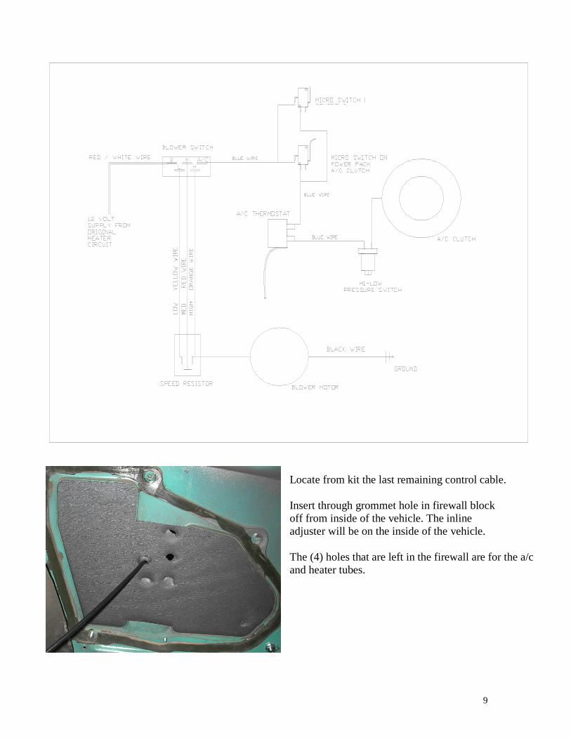
Locate from kit the last remaining control cable.
Insert through grommet hole in firewall block
off from inside of the vehicle. The inline
adjuster will be on the inside of the vehicle.
The (4) holes that are left in the firewall are for the a/c
and heater tubes.
10
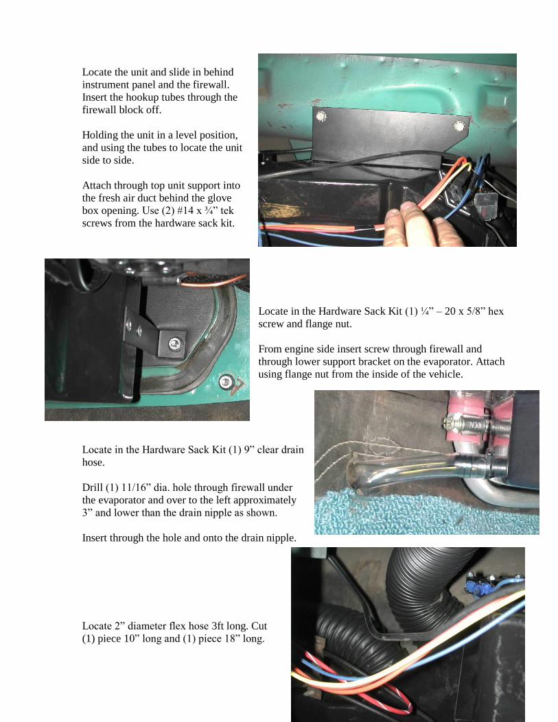
Locate the unit and slide in behind
instrument panel and the firewall.
Insert the hookup tubes through the
firewall block off.
Holding the unit in a level position,
and using the tubes to locate the unit
side to side.
Attach through top unit support into
the fresh air duct behind the glove
box opening. Use (2) #14 x ¾” tek
screws from the hardware sack kit.
Locate in the Hardware Sack Kit (1) ¼” – 20 x 5/8” hex
screw and flange nut.
From engine side insert screw through firewall and
through lower support bracket on the evaporator. Attach
using flange nut from the inside of the vehicle.
Locate in the Hardware Sack Kit (1) 9” clear drain
hose.
Drill (1) 11/16” dia. hole through firewall under
the evaporator and over to the left approximately
3” and lower than the drain nipple as shown.
Insert through the hole and onto the drain nipple.
Locate 2” diameter flex hose 3ft long. Cut
(1) piece 10” long and (1) piece 18” long.
11
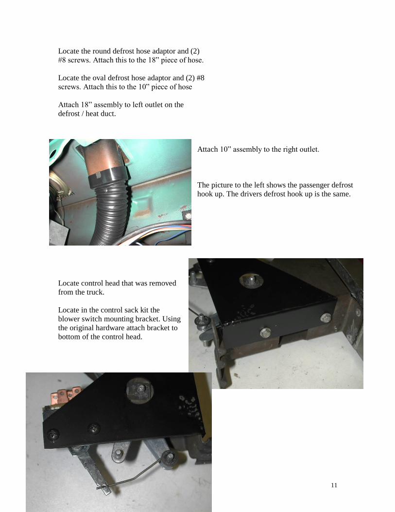
Locate the round defrost hose adaptor and (2)
#8 screws. Attach this to the 18” piece of hose.
Locate the oval defrost hose adaptor and (2) #8
screws. Attach this to the 10” piece of hose
Attach 18” assembly to left outlet on the
defrost / heat duct.
Attach 10” assembly to the right outlet.
The picture to the left shows the passenger defrost
hook up. The drivers defrost hook up is the same.
Locate control head that was removed
from the truck.
Locate in the control sack kit the
blower switch mounting bracket. Using
the original hardware attach bracket to
bottom of the control head.
12
Locate the blower switch, control wire, (1) push nut, and (2) #8 x 3/8 pan head screws.
Attach blower switch to the control bracket as shown.
Attach wire through the blower switch hole and then over the center lever pin. Secure with push
nut.
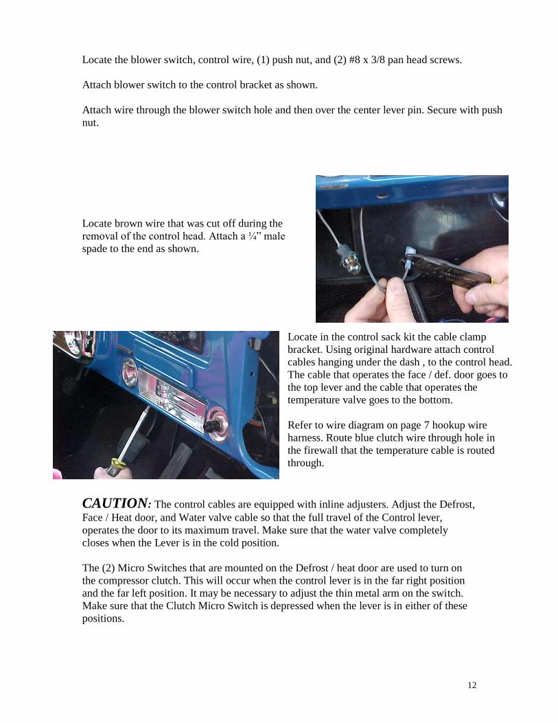
Locate brown wire that was cut off during the
removal of the control head. Attach a ¼” male
spade to the end as shown.
Locate in the control sack kit the cable clamp
bracket. Using original hardware attach control
cables hanging under the dash , to the control head.
The cable that operates the face / def. door goes to
the top lever and the cable that operates the
temperature valve goes to the bottom.
Refer to wire diagram on page 7 hookup wire
harness. Route blue clutch wire through hole in
the firewall that the temperature cable is routed
through.
CAUTION: The control cables are equipped with inline adjusters. Adjust the Defrost,
Face / Heat door, and Water valve cable so that the full travel of the Control lever,
operates the door to its maximum travel. Make sure that the water valve completely
closes when the Lever is in the cold position.
The (2) Micro Switches that are mounted on the Defrost / heat door are used to turn on
the compressor clutch. This will occur when the control lever is in the far right position
and the far left position. It may be necessary to adjust the thin metal arm on the switch.
Make sure that the Clutch Micro Switch is depressed when the lever is in either of these
positions.
13
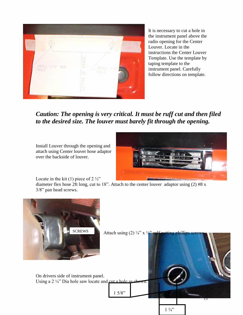
1 ¾”
1 5/8”
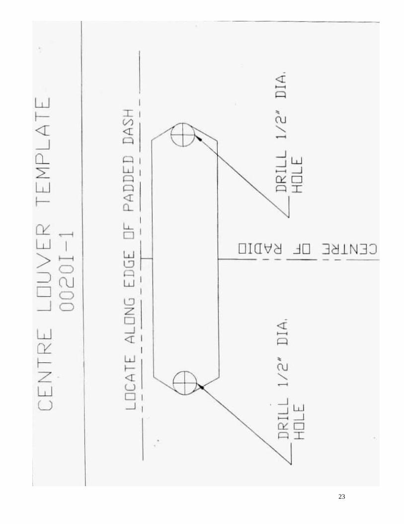
It is necessary to cut a hole in
the instrument panel above the
radio opening for the Center
Louver. Locate in the
instructions the Center Louver
Template. Use the template by
taping template to the
instrument panel. Carefully
follow directions on template.
Caution: The opening is very critical. It must be ruff cut and then filed
to the desired size. The louver must barely fit through the opening.
Install Louver through the opening and
attach using Center louver hose adaptor
over the backside of louver.
Locate in the kit (1) piece of 2 ½”
diameter flex hose 2ft long, cut to 18”. Attach to the center louver adaptor using (2) #8 x
3/8” pan head screws.
Attach using (2) ¼” x ½” self cutting phillips screws.
On drivers side of instrument panel.
Using a 2 ¼” Dia hole saw locate and cut a hole as shown.
SCREWS
14
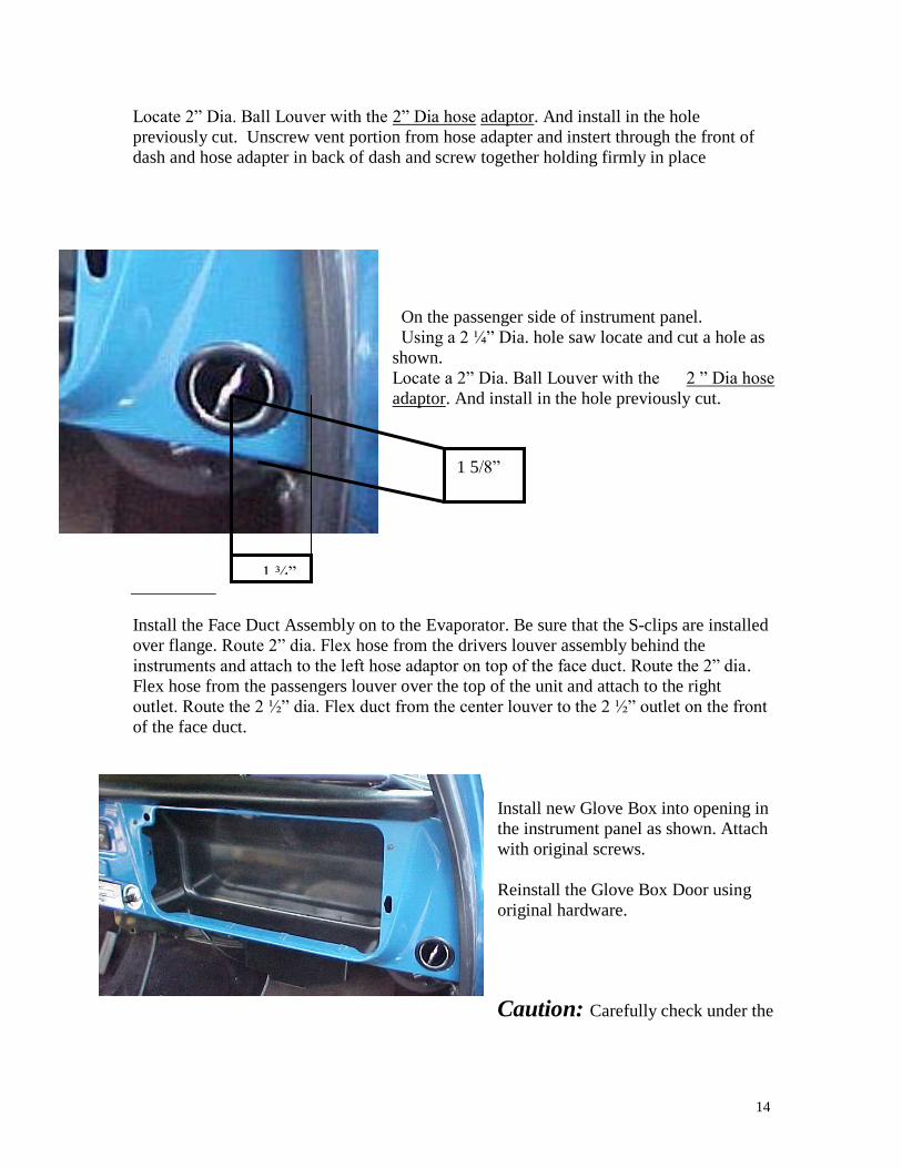
1 ¾”
1 5/8”
Locate 2” Dia. Ball Louver with the 2” Dia hose adaptor. And install in the hole
previously cut. Unscrew vent portion from hose adapter and instert through the front of
dash and hose adapter in back of dash and screw together holding firmly in place
On the passenger side of instrument panel.
Using a 2 ¼” Dia. hole saw locate and cut a hole as
shown.
Locate a 2” Dia. Ball Louver with the 2 ” Dia hose
adaptor. And install in the hole previously cut.
Install the Face Duct Assembly on to the Evaporator. Be sure that the S-clips are installed
over flange. Route 2” dia. Flex hose from the drivers louver assembly behind the
instruments and attach to the left hose adaptor on top of the face duct. Route the 2” dia.
Flex hose from the passengers louver over the top of the unit and attach to the right
outlet. Route the 2 ½” dia. Flex duct from the center louver to the 2 ½” outlet on the front
of the face duct.
Install new Glove Box into opening in
the instrument panel as shown. Attach
with original screws.
Reinstall the Glove Box Door using
original hardware.
Caution: Carefully check under the
15
Instrument Panel for all cables, electrical harness, or Flex Ducting that might interfere with the safe operation of the vehicle.
IT IS NOW TIME TO INSTALL THE COMPRESSOR AND THE CONDENSER
REMOVE BATTERY AND SET ASIDE.
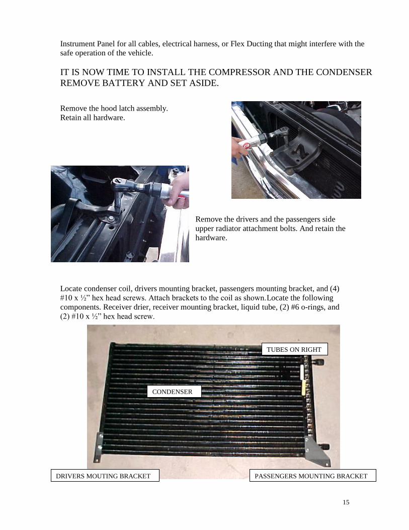
Remove the hood latch assembly.
Retain all hardware.
Remove the drivers and the passengers side
upper radiator attachment bolts. And retain the
hardware.
Locate condenser coil, drivers mounting bracket, passengers mounting bracket, and (4)
#10 x ½” hex head screws. Attach brackets to the coil as shown.Locate the following
components. Receiver drier, receiver mounting bracket, liquid tube, (2) #6 o-rings, and
(2) #10 x ½” hex head screw.
CONDENSER
DRIVERS MOUTING BRACKET PASSENGERS MOUNTING BRACKET
TUBES ON RIGHT
16
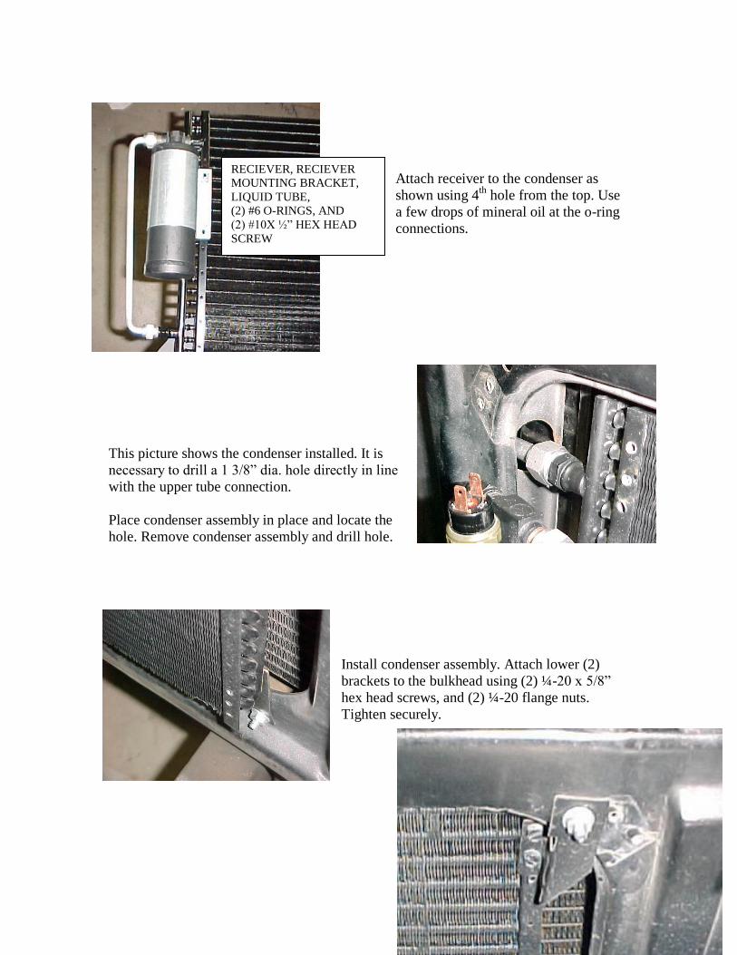
Attach receiver to the condenser as
shown using 4th
hole from the top. Use
a few drops of mineral oil at the o-ring
connections.
This picture shows the condenser installed. It is
necessary to drill a 1 3/8” dia. hole directly in line
with the upper tube connection.
Place condenser assembly in place and locate the
hole. Remove condenser assembly and drill hole.
Install condenser assembly. Attach lower (2)
brackets to the bulkhead using (2) ¼-20 x 5/8”
hex head screws, and (2) ¼-20 flange nuts.
Tighten securely.
RECIEVER, RECIEVER
MOUNTING BRACKET,
LIQUID TUBE,
(2) #6 O-RINGS, AND
(2) #10X ½” HEX HEAD
SCREW
17
Locate Upper Drivers mounting bracket, (2) #10 x ½” hex head screws, (1) ¼-20 x 5/8” hex head screw, and (1) ¼-20 flange nut.
Attack bracket to the condenser and bulkhead as shown. tighten securely.
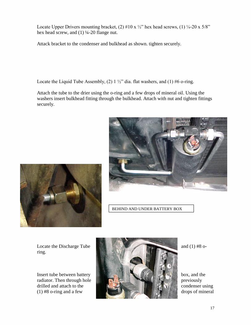
Locate the Liquid Tube Assembly, (2) 1 ½” dia. flat washers, and (1) #6 o-ring.
Attach the tube to the drier using the o-ring and a few drops of mineral oil. Using the
washers insert bulkhead fitting through the bulkhead. Attach with nut and tighten fittings
securely.
Locate the Discharge Tube and (1) #8 o-
ring.
Insert tube between battery box, and the
radiator. Then through hole previously
drilled and attach to the condenser using
(1) #8 o-ring and a few drops of mineral
BEHIND AND UNDER BATTERY BOX
18
oil.
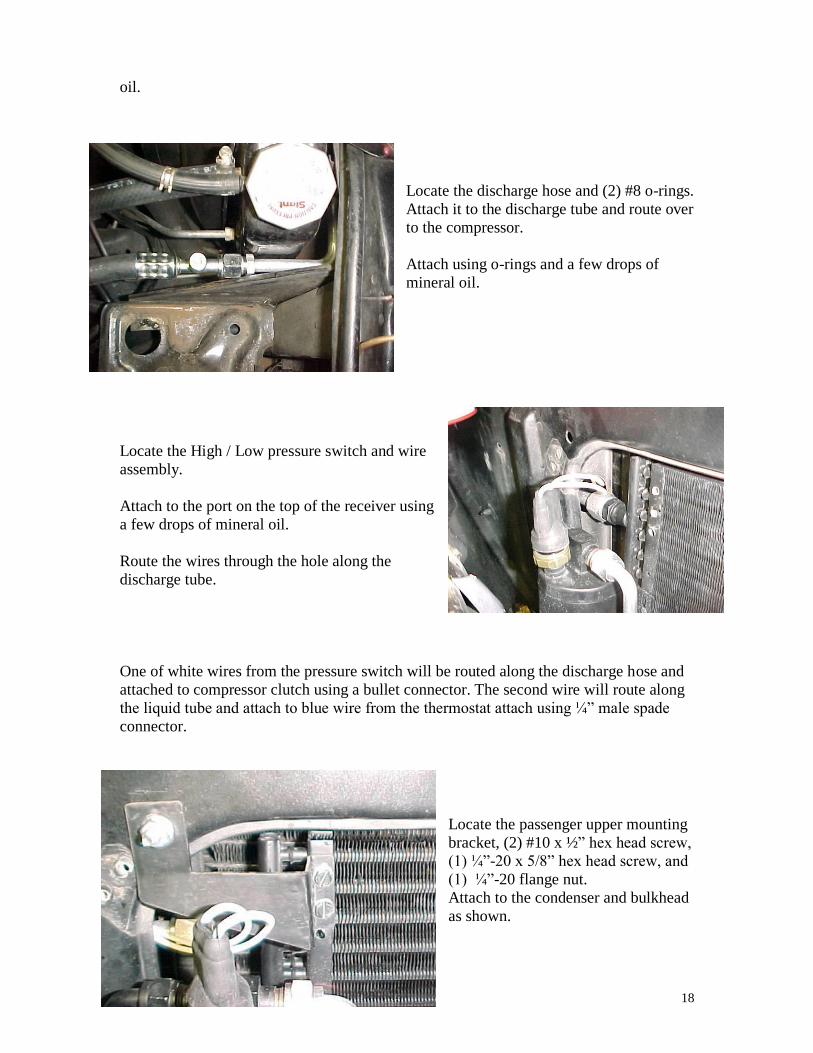
Locate the discharge hose and (2) #8 o-rings.
Attach it to the discharge tube and route over
to the compressor.
Attach using o-rings and a few drops of
mineral oil.
Locate the High / Low pressure switch and wire
assembly.
Attach to the port on the top of the receiver using
a few drops of mineral oil.
Route the wires through the hole along the
discharge tube.
One of white wires from the pressure switch will be routed along the discharge hose and
attached to compressor clutch using a bullet connector. The second wire will route along
the liquid tube and attach to blue wire from the thermostat attach using ¼” male spade
connector.
Locate the passenger upper mounting
bracket, (2) #10 x ½” hex head screw,
(1) ¼”-20 x 5/8” hex head screw, and
(1) ¼”-20 flange nut.
Attach to the condenser and bulkhead
as shown.
19
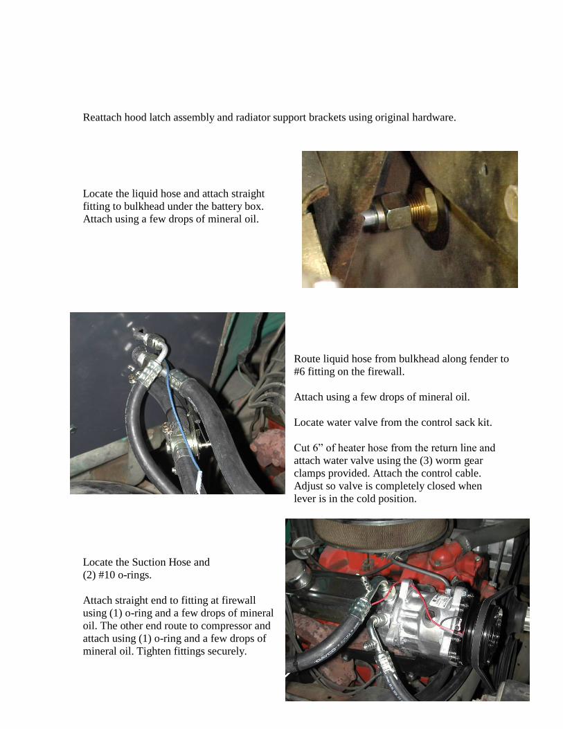
Reattach hood latch assembly and radiator support brackets using original hardware.
Locate the liquid hose and attach straight
fitting to bulkhead under the battery box.
Attach using a few drops of mineral oil.
Route liquid hose from bulkhead along fender to
#6 fitting on the firewall.
Attach using a few drops of mineral oil.
Locate water valve from the control sack kit.
Cut 6” of heater hose from the return line and
attach water valve using the (3) worm gear
clamps provided. Attach the control cable.
Adjust so valve is completely closed when
lever is in the cold position.
Locate the Suction Hose and
(2) #10 o-rings.
Attach straight end to fitting at firewall
using (1) o-ring and a few drops of mineral
oil. The other end route to compressor and
attach using (1) o-ring and a few drops of
mineral oil. Tighten fittings securely.
20
THE ENGINE COMPARTMENT OF YOUR SYSTEM IS COMPLETE.
THE UNIT IS READY FOR EVACUATION AND CHARGING.
THIS SHOULD BE DONE BY A QUALIFIED AND CERTIFIED AIR
CONDITIONING TECHNICIAN.
Congratulations you have completed the install of your
CLASSIC AUTO AIR “Perfect Fit Series” system.
NOTE: COMPRESSOR IS SUPPLIED WITH THE
CORRECT OIL CHARGE. DO NOT ADD OIL TO SYSTEM.
134a SYSTEMS 24 oz OF REFRIGERANT
Recommend that power fuse is 25amp minimum
21
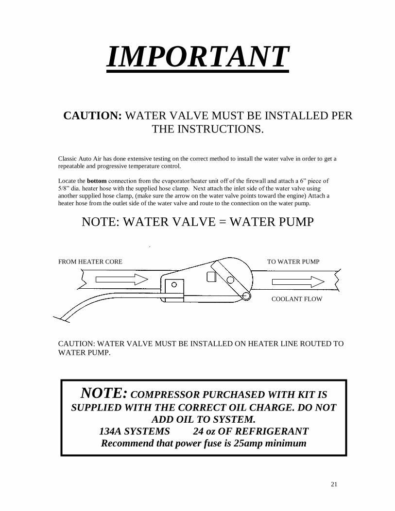
IMPORTANT
CAUTION: WATER VALVE MUST BE INSTALLED PER
THE INSTRUCTIONS.
Classic Auto Air has done extensive testing on the correct method to install the water valve in order to get a
repeatable and progressive temperature control.
Locate the bottom connection from the evaporator/heater unit off of the firewall and attach a 6” piece of
5/8” dia. heater hose with the supplied hose clamp. Next attach the inlet side of the water valve using
another supplied hose clamp, (make sure the arrow on the water valve points toward the engine) Attach a
heater hose from the outlet side of the water valve and route to the connection on the water pump.
NOTE: WATER VALVE = WATER PUMP
CAUTION: WATER VALVE MUST BE INSTALLED ON HEATER LINE ROUTED TO
WATER PUMP.
NOTE: COMPRESSOR PURCHASED WITH KIT IS
SUPPLIED WITH THE CORRECT OIL CHARGE. DO NOT
ADD OIL TO SYSTEM.
134A SYSTEMS 24 oz OF REFRIGERANT
Recommend that power fuse is 25amp minimum
TO WATER PUMP FROM HEATER CORE
COOLANT FLOW

22
23