pegasus 9703 gas appliance - blaze king · om-9703 page 1 date printed: thursday, july 05, 2007...
TRANSCRIPT
PAGE 1OM-9703
Date Printed: Thursday, July 05, 2007Revision Date: March 6, 2006
BLAZE KINGPRODUCTS
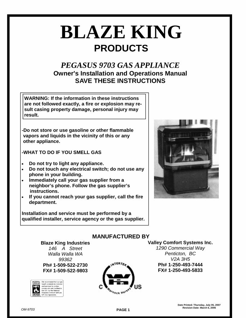
PEGASUS 9703 GAS APPLIANCEOwner's Installation and Operations Manual
SAVE THESE INSTRUCTIONS
Blaze King Industries146 A StreetWalla Walla WA
99362Ph# 1-509-522-2730FX# 1-509-522-9803
Valley Comfort Systems Inc.1290 Commercial Way
Penticton, BCV2A 3H5
Ph# 1-250-493-7444FX# 1-250-493-5833
MANUFACTURED BY
-Do not store or use gasoline or other flammablevapors and liquids in the vicinity of this or anyother appliance.
-WHAT TO DO IF YOU SMELL GAS
Do not try to light any appliance. Do not touch any electrical switch; do not use any
phone in your building. Immediately call your gas supplier from a
neighbor’s phone. Follow the gas supplier’sinstructions.
If you cannot reach your gas supplier, call the firedepartment.
Installation and service must be performed by aqualified installer, service agency or the gas supplier.
WARNING: If the information in these instructionsare not followed exactly, a fire or explosion may re-sult casing property damage, personal injury mayresult.

PAGE 2OM-9703
Date Printed: Thursday, July 05, 2007Revision Date: March 6, 2006
Dear Customer:
Thank you for purchasing this Blaze King gas appliance. It is our goal to haveevery purchaser of a Blaze King stove be a satisfied customer. This owner’smanual explains the steps required to safely assemble, install, operate, andmaintain your new appliance.
Be a responsible appliance owner. Carefully read these requirements for safeinstallation and proper operation BEFORE installing and using your appliance.Check local building and Fire Codes before installing your appliance. If local lawsrequire them, obtain permits from the Building Inspector or Fire Department. Whenyou have completed the installation, have it checked by your local inspector.Disregarding inspection and code requirements may jeopardize your safety and/orhomeowner’s insurance. Since some insurance carriers require notification of anappliance installation we recommend you contact your insurance agent . We wantyour Blaze King to give you a lifetime of trouble-free operation.
We have made every effort to make these installation and operating instructionsas complete as possible. If you have any questions that have not been answeredhere, contact your BLAZE KING dealer, Local Building Inspector, or FireDepartment.
The management and Employees of BLAZE KING
.
KEEP THIS MANUAL FOR FUTURE REFERENCE
Mail your warranty card TODAY, andSAVE your BILL OF SALE.
In order to receive full warranty coverageand to expedite service, BKI recommendsthat your save your bill of sale and attach itto this page
By doing this you will have all the necessaryinformation in the event the your stove mayneed service
Your Blaze King Stove has itsown personal serial number, notwo stoves are alike. The serialnumber is located on the stovelabel attached to a plate hangingon a hook on the left side of thefire box

PAGE 3OM-9703
Date Printed: Thursday, July 05, 2007Revision Date: March 6, 2006
SPECIFICATIONS MODEL 9703 ........................................................................................................... 4
SAFETY NOTICE .................................................................................................................................... 5
WARRANTY ............................................................................................................................................ 6
WHITE MINERAL DEPOSITS................................................................................................................. 7
COPY OF APPROVAL LABEL................................................................................................................ 8
ELECTRICAL GROUNDING INSTRUCTIONS....................................................................................... 9
CAUTION ................................................................................................................................................ 9
PLANNING YOUR STOVE PLACEMENT ............................................................................................ 10
Z 9723 INSERT KIT........................................................................................................ ...................... 11
AIR SHUTTER ADJUSTMENT ............................................................................................................ 15
OAK LOG INSTALLATION AND POSITIONING .................................................................................. 15
GAS CONNECTIONS ........................................................................................................................... 16
CLEARANCE DIAGRAM ...................................................................................................................... 16
FLUE VENTING..................................................................................................................................... 17
ORIFICE SIZING TABLE....................................................................................................................... 17
BURNER CONVERSION INSTRUCTIONS .......................................................................................... 18
PILOT CONVERSION ........................................................................................................................... 19
WIRING DIAGRAMS ............................................................................................................................. 20
LIGHTING PREPARATION................................................................................................................... 20
LIGHTING INSTRUCTIONS.................................................................................................................. 21
PARTS LIST .......................................................................................................................................... 22
TABLE OF CONTENTS

PAGE 4OM-9703
Date Printed: Thursday, July 05, 2007Revision Date: March 6, 2006
SPECIFICATIONS - 9703
Gas Appliance Rating Natural Gas L P Gas
Freestanding / Insert Freestanding / Insert
Input Rating (BTU/hr) 0-610m (0-2000 ft.) ALT 44,000 42,000
Orifice Size (DMS) 610m #48 (Front) & #33 (Back) #62 (Front) & #52 (Back)
Input Rating (Btu/hr) 610-1370 m (2000-4500 ft) ALT 41,000 39,000
Orifice Size (DMS) 1370m #49 (Front) & #33 (Back) #63 (Front) & #52(Back)
Unit Factory Equipped For 0-610m (0-2000 ft.)
Minimum Input (BTU/hr) 25,000 20,500
Manifold Pressure (in w.c./kPa) 3.5 / 0.87 11.0 / 2.74
Manifold Pressure Lo-Setting (in w.c./kPa) 1.3 / 0.42 2.7 / 0.67
Minimum Inlet Pressure (in w.c./kPa) 4.5 / 1.12 12.2 / 3.04
Maximum Inlet Pressure (in w.c. / kPa) 10.5 / 2.62 13.0 / 3.24
Shipping Weights & Dimensions Freestanding Fire Box Only Shroud
Width 31.5” 28.5” 48”
Height 36” 24” 30”
Depth 24” 22.5” 3”
Weight 237 lbs. 170 lbs. 54 lbs.
Insert Units can only be installed in a masonary fireplace ora listed wood burning “0” clearance fireplace.

PAGE 5OM-9703
Date Printed: Thursday, July 05, 2007Revision Date: March 6, 2006
CAUTIONS
NEVER vent the appliance to other rooms or buildings. The appliance must be vented to theoutside ONLY.
NEVER burn the appliance with the viewing door open.
FIRE EXTINGUISHER:Every home should have at least one approved Class A-B-C fire extinguisher. Thisextinguisher should be mounted on the wall near an exit, and close to the appliance, but not soclose that accessibility to the extinguisher could be blocked by a fire. Your local FireDepartment can advise you concerning the most appropriate location.
BUILDING AND FIRE CODES, PERMITS AND INSPECTIONS:The installation of this gas appliance must comply with your local building and fire codes.Always contact your local Building Inspector and/or Fire Department before beginning theinstallation process. If required, obtain a permit before installation and have the completedinstallation inspected. Remember that not complying with building and/or fire codes mayjeopardize your homeowner’s insurance.
CHILDREN:Do NOT allow children to play near the appliance or with the controls. Severe burns may beresult when touching the door or glass, the front, sides or top of the appliance. Train children tostay away from the appliance, and never leave children unattended in the room when theappliance is in operation.
SMOKE DETECTORS and CARBON MONOXIDE DETECTORS (CO-DETECTORS):Install at least one smoke detector on each floor of your home to ensure your safety. It shouldbe located away from the gas appliance and close to the sleeping areas. Follow the smokedetector manufacturers placement installation and maintenance instructions. Your local FireDepartment may provide assistance in selecting smoke detectors and CO-detectors. For yourfamilies protection, it is strongly recommended that a CO-detector be placed in all homes thatutilize gas in any form.
THE APPLIANCE AREA MUST BE KEPT CLEAR FROM COMBUSTIBLE MATERIALS,GASOLINE AND OTHER FLAMMABLE VAPORS OR LIQUIDS.
SAFETY NOTICE
IF THIS APPLIANCE IS NOT PROPERLY INSTALLED, A HOUSE FIRE, OR EXPLOSIONMAY RESULT. FOR YOUR SAFETY, FOLLOW THE INSTALLATION DIRECTIONS.CONTACT LOCAL BUILDING OR FIRE OFFICIALS ABOUT RESTRICTIONS ANDINSTALLATION REQUIREMENTS IN YOUR AREA. PLEASE READ THIS ENTIREMANUAL BEFORE YOU INSTALL AND USE YOUR NEW APPLIANCE. FAILURE TOFOLLOW INSTRUCTIONS MAY RESULT IN PROPERTY DAMAGE, BODILY INJURY or

PAGE 6OM-9703
Date Printed: Thursday, July 05, 2007Revision Date: March 6, 2006
Gas stoves manufactured by Blaze King Industries and/or Valley Comfort Systems Inc. are covered by a limitedlifetime warranty against manufacturers defects in material and workmanship. Details of this comprehensivewarranty program are outlined below. In addition to the terms outlined for the limited lifetime warranty, ourproducts carry a 5 year warranty which covers mechanical and electrical components including labor costsoutlined below. The combination of these warranty policies provide a very strong coverage package that we areproud to offer you, our customers. Our Blaze King tradition of building high quality products for over 25 years isreally your most important assurance of quality but it's nice to know that should something fail (and it occasionallydoes) you are covered by a warranty policy that leads the industry. To ensure the coverage is in place you musthave your unit properly installed by an authorized Blaze King dealer and you must register your ownership. BlazeKing's warranty policy applies only to units sold, installed and/or for use in the USA or Canada. No personis authorized to modify this warranty or make any additional warranties on behalf of the manufacturer,Blaze King.Components and parts 5 year warranty:Blaze King warrants the following parts; blower motors, door gasket, blower speed control, logs, pilot assembly,gas valve, gas lines, thermocouple and/or thermopile against defects in material or workmanship to the originalpurchaser, for five years following the date of purchase.Labor costs during the 5 year warranty period:Blaze King manufacturers warranty covers labor costs to the original purchaser based on our schedule ofapproved charges, provided to our authorized dealers. Blaze King will only be responsible for labor costsprovided by our authorized dealers and based upon the schedule.Limited Lifetime CoverageThis warranty contains different terms that cover specific parts of the gas appliance. Blaze King warrants thefollowing parts of the gas appliance against defects in material or workmanship to the original retail purchaser. Forthe first five years of ownership, the combustion chamber, heat exchanger and burners will be replaced by BlazeKing, conditional upon production availability. From year 6 through to the end of ownership by the originalpurchaser, Blaze King will provide replacement or repair of the aforementioned parts, conditional upon currentproduction availability, at 50% of current retail price but does not cover any charges relating to labor. This portionof the warranty coverage is not transferable and applies only to the original purchaser.How to Get ServiceIf this product requires repair or replacement due to defects in material or craftsmanship during the first five yearsof ownership, contact your Blaze King dealer and explain the nature of the problem. If the dealer is unable torepair or replace the product to your satisfaction then contact Blaze King at 509-522-2730 in the USA or 250-493-7444 in Canada. If a replacement part is sent directly to you, please contact Blaze King to obtain a ReturnAuthorization Number (RA#) for all defective parts. Blaze King will refuse delivery of any returned packages notclearly showing an (RA#). All expenses relating to the shipping of defective parts or entire stoves will be atpurchaser's expense.Blaze Kings Responsibilities:If the purchaser has complied with all the terms and conditions of this warranty and if the purchaser has notifiedBlaze King of the defect prior to the expiration of any warranted items, the following procedure will occur. BlazeKing will inspect the product to determine that there is indeed a defect and that the defect is covered by warranty.Blaze King will either repair or replace the product at its' discretion. Under no condition whatsoever does BlazeKing provide or imply warranty coverage for venting components used in the installation of our products. Thiswarranty details the obligations and liabilities of Blaze King and no other warranties are expressed or implied.Blaze King reserves the right to investigate and settle all claims against warranted parts at their discretion. In noevent shall Blaze King be held responsible for indirect or consequential damages of any nature which are inexcess of the original purchase price of the product. Blaze King may at its' discretion discharge any or allobligations by refunding the wholesale price of any defective part or parts.Misuse of Stove Nullifies Warranty:The above warranty is conditioned upon the proper installation and use of the product according to themanufacturers instructions as specified in the "Owners Installation & Operations Instructions" and incompliance with applicable local building and fire codes. Blaze King recommends the local building inspector orfire department inspect the unit prior to initial use. Consult the "Owners Installation & Operations Instructions"supplied with each unit prior to installation or operation. Alteration, abuse, lack of maintenance, faulty repairs ormisuse will void the warranty. Abuse includes but is not limited to the use of fuels other than as specified in the"Owners Installation & Operations Instructions."
BLAZE KING LIMITED LIFETIME WARRANTY

PAGE 7OM-9703
Date Printed: Thursday, July 05, 2007Revision Date: March 6, 2006
The front door of your new Blaze King direct vent is gasketed and has been adjusted for a tight seal. As with alldirect vent appliances, a tight seal is necessary for maximum performance and proper venting of combustion prod-ucts. With use the door gasket material may compress and the door may require periodic adjustments to maintaina proper seal. The time to make these adjustments will vary depending upon individual hours of use, btu settings,and frequency of opening and closing the door. Check the door on your appliance periodically, especially duringthe first 90 days of operation, to ensure it is sealing properly. Your Blaze King dealer/installer should be contactedto properly adjust the door if required.
One of the byproducts of the combustion process in a gas appliance is a mineral which can show up as a whitefilm on the ceramic glass of the viewing door. The composition of the deposit varies widely from location tolocation and also from time to time in the same locations. You may have the problem for a time and then not see itfor many months when it will reappear in your area. It seems this is associated with the varying sulfur content ofthe gas. We have discussed this problem with ceramic glass manufacturers and they cannot give us a definitiveanswer to this problem. We have input from several dealers who have tried different cleaning products withvarying results. We can only make the following recommendations but we cannot guarantee results in very case.
WARNING!!Never clean the ceramic glass or any other part of the appliance while it is still hot. Please shut
off your appliance and wait for it to cool down prior to cleaning.
1) Clean the glass regularly as soon as you notice the buildup (white film). If the film is left for a long period oftime it will build up and bake on making it hard or almost impossible to remove
2) NEVER use an abrasive cleaner on the ceramic glass. Any abrasion of the surface will immediately affect thestrength of the glass. An emulsion type cleaner is best.
3) Use a soft, damp, preferably cotton, cloth to apply the cleaner and a soft, dry cloth to dry the glass. Most papertowels and synthetic materials are abrasive to ceramic glass and should be avoided.
WHITE OFF by Rutland has been tested and shown to be effective in removing ugly mineral deposits fromceramic glass.NOTE: This is a problem beyond BLAZE KING'S control and is not covered under warranty.
Legal Rights of Purchaser:This warranty gives you specific legal rights and you may have other rights that vary from state to state (orprovince to province).Blaze King Assurance Plan:Included with each gas stove manufactured by Blaze King is a Warranty Card, which must be completed in itsentirety and returned to Blaze king within ten days from the date of purchase. Blaze King will be unable toproperly administer the warranty if the card is not completed and registered on file.The Protection Plan will pay to repair and or replace parts which fail under normal usage at labor rates establishedby this Agreement. Extra charges such as mileage, overtime or shipping are not covered. Nuisance calls are notcovered by the Plan. This Plan is for residential stoves and does not apply to commercial applications. Onlyrepairs attributed to normal failure of the electronic and mechanical functions of the stove are covered. Failuredue but not limited to, abuse, negligence, impact, fire, lightning, power failures and or surges, rust and corrosionare not covered. Damage and or repairs to cabinets and all exterior components, remote controls, and normalmaintenance , related duct work, power surges, electrical spikes or electrical circuit overloads, filters, knobs, glass,gaskets, block and tile etc., are not covered. Additional or unusual utility bills incurred due to any malfunction ordefect in equipment listed on the Plan, labor cost of gaining access to or removal of a unit that requires specialequipment or tools such as cranes, ladder trucks, etc., are not covered. These include but are not limited to,cleaning, adjustments of the customer controls and customer product education. Labor, materials, expenses orequipment required to comply with the law and or regulations set forth by any governmental agencies are notcovered by this Plan.
BLAZE KING LIMITED LIFETIME WARRANTY
WHITE MINERAL DEPOSITS
DOOR SEAL GASKET

PAGE 8OM-9703
Date Printed: Thursday, July 05, 2007Revision Date: March 6, 2006
APPROVAL LABEL
WH-
This stove is factory equipped for 0-
Natural Gas • Propane Gas •
Tested to ANSI Z21.88b-2003•CSA 2.33B-2003 “Vented Gas
Fireplace Heaters” and CAN/CGA 2.17 –M91”Gas-Fired Appliances for use at High Altitudes”
NATURAL GAS LP GAS
Input rating (BTU/hr) 0-610m 0-2,000 ft 44,000 42,000
Orifice (DMS) 0-610 m 48 Front 33 Back 62 Front 52 Back
Input rating (BTU/hr) 610-1370m 2,000 -4,500 ft Alt. 41,000 39,000
Orifice (DMS)610-1370 m 49 Front 33 Back 63 Front 52 back
Minimum input (Btu/hr) 25,000 20,500
Manifold Pressure (In w.c.) 3.5 11.0
Manifold Pressure Lo setting(In w.c.) 1.3 2.7
Minimum Inlet Pressure (In w.c.) 5.0 12.3
FOR USE WITH GLASS DOORS CERTIFIED WITH THE APPLIANCE ONLY
NOT FOR USE WITH SOLID FUEL.
MINIMUM CLEARANCES FROM COMBUSTIBLE CONSTRUCTION
Unit to Sidewall 10 in.
Unit to Backwall 6 in. (to flue collar)
Unit to Adjacent Wall Corner 2 in.
Alcove: Minimum 50 in.
Minimum Height 60 in.
Maximum Depth 30 in.
Minimum Mantel Height 27" Above the top of unit
15" Floor protection required if unit is not on a 6" elevated Hearth (insert only)
For more details, see Instruction Manual
Electrical Rating: 115 Volts, 1 Amp, 60 Hz
DANGER: Risk of electrical shock. Disconnect power before servicing unit.
Do not route power cord beneath heater.
Manufactured By: Manufactured Date:
•2005 •2006 •2007 •2008
•JAN •FEB •MAR •APRIL
•MAY •JUNE •JULY •AUG
•SEPT •OCT •NOV •DEC
Blaze King 9703Vented Gas Fireplace HeaterNot For Use With Solid Fuel
Not for installation in a Mobile Home
This appliance must be installed in accordance with the manufacture’s instructions. This appliance must be in-stalled in accordance with local codes if any; if not follow the current ANSI Z223.1 or CAN/CGA-B149.1. Thisvented gas fireplace is not for use with air filters. For use with glass doors certified with the appliance only.
Blaze King Industries146A StreetWalla Walla, WA99362Ph# 1-509-522-2730
Valley Comfort Systems Inc.1290 Commercial WayPenticton, BC V2A 3H5Ph# 1-250-493-7444
0754H Rev Re: Mar 8 letter

PAGE 9OM-9703
Date Printed: Thursday, July 05, 2007Revision Date: March 6, 2006
ELECTRICAL GROUNDING INSTRUCTIONS
ELECTRICAL GROUNDING INSTRUCTIONSWARNING: The appliance, when installed, must be electrically grounded in accordance with local codes or in theabsence of local codes with the current edition of National Electrical Code ANSI/NFPA 70, or the current CanadianElectrical Code CSA.C22.1
This appliance is equipped with a three prong (grounding) plug for your protection against shock hazard andshould be plugged directly into a properly grounded three prong receptacle.DO NOT cut or remove the ground prong from this plug.
This appliance installation must conform with local codes and with the current edition of National Fuel Gascode ANSI Z223.1 or CAN 1-B149.1
The appliance and its individual shut off valve must be disconnected from the gas supply piping system duringany pressure testing of that system at test pressures in excess of 1/2 psi (3.5 kPa)
The appliance must be isolated from the gas supply piping system by closing its individual manual shut offvalve during any pressure testing of the gas supply piping system at test pressures equal to or less than 1/2psi (3.5 kPa). The appliance installer must provide a 1/2 inch N.P.T. plugged tapping accessibility for testgage connection immediately upstream of the gas supply connection to the appliance.
Should overheating occur or the gas supply fail to shut off, shut off the manual gas valve to the appliancebefore shutting off the electrical supply.
Due to high temperatures, the appliance should be located out of traffic and away from furniture and draperies.
Children and adults should be alerted to the hazards of high surface temperatures and should stay away toavoid burns or clothing ignition.
Young children should be carefully supervised when they are in the same room as the appliance.
Clothing or other flammable material should not be placed on or near the appliance.
Any safety screen or guard removed for servicing a room heater must be replaced prior to operating theappliance.
Installation and repair should be done by a qualified service person.
WARNING: DO NOT OPERATE APPLIANCE WITH THE GLASS DOOR REMOVED,OPENED, CRACKED, OR BROKEN. REPLACEMENT OF GLASS SHOULD BE DONE BYA LICENSED OR QUALIFIED SERVICE PERSON AS AUTHORIZED BY BLAZE KING. DONOT USE SUBSTITUTE MATERIALS. DO NOT ABUSE GLASS BY STRIKING ORSLAMMING DOOR SHUT. DO NOT USE ABRASIVE CLEANERS OR CLEAN WHILE HOT.FOR INSTRUCTIONS ON REPLACING THE GLASS IN YOUR APPLIANCE PLEASE SEETHE INSTRUCTIONS ON PAGE 22 OF THIS MANUAL.
WARNINGIMPROPER ASSEMBLY AND/OR INSTALLATION OF YOUR BLAZE KING GASAPPLIANCE OR FAILURE TO OPERATE IT ACCORDING TO THE GUIDELINESDETAILED IN THESE INSTRUCTIONS WILL VOID THE APPLIANCE WARRANTY, CANCAUSE A HOUSE FIRE, AND MAY ENDANGER YOUR FAMILY. FOR YOUR SAFETY,FOLLOW THE ASSEMBLY AND INSTALLATION INSTRUCTIONS CAREFULLY.CONTACT LOCAL BUILDING OR FIRE OFFICIALS ABOUT RESTRICTIONS ANDINSTALLATION INSPECTIONS IN YOUR AREA. PLEASE READ THIS ENTIRE MANUALBEFORE YOU INSTALL AND USE YOUR NEW APPLIANCE.
CAUTION

PAGE 10OM-9703
Date Printed: Thursday, July 05, 2007Revision Date: March 6, 2006
The appliance and venting should be inspected before use and annually afterwards by a qualified serviceperson.
More frequent cleaning may be required due to excessive lint from carpeting, bedding materials, etc.
It is imperative that control compartments, burners, and circulating air passageways of the appliance are keptclean.
When cleaning the stove, make sure the appliance is off and cold. Remove the logs and embers and use avacuum to clean the burner and air openings in the bottom and at the back of the appliance. Replace the logsand embers.
The draft hood must be in the same atmospheric pressure zone as the combustion air inlet. The flow ofcombustion and ventilation air must not be obstructed.
Do not use this heater if any part has been under water. Immediately call a qualified service technician toinspect the heater and to replace any part of the control system and any gas control which has been underwater.
CAUTION
As you plan your installation, consider the following:
The stove should be placed as centrally in the home as possible. Consider safety, convenience, traffic flow, andthe fact that the stove will need a venting system.
DUE TO HIGH TEMPERATURES, THE ROOM HEATER SHOULD BE LOCATED OUT OFTRAFFIC AREAS AND AWAY FROM FURNITURE OR DRAPERIES. MINIMUMCLEARANCES SHOWN ON PAGE 16 ARE TO PREVENT WALLS AND CEILINGS FROMCATCHING ON FIRE.
See page 17 for the type of vent system to be used for both Freestanding Kit and Insert Kit. Power needed is115-60 HZ. The stove is equipped with a fan assembly having a six foot electrical cord. Do not route the cord infront of the stove. Position the stove in its final location. A floor protector may be used for aesthetics but is notrequired. The freestanding 9703 units may be installed directly onto carpet, vinyl, or any other flooring.
WARNINGONLY PERSONS LICENSED TO WORK WITH GAS PIPING MAY MAKE THE NECESSARY GAS CONNECTION TO THIS APPLIANCE.YOU ARE NOW READY TO HOOK UP THE GAS SUPPLY. BE SURE GAS PLUMBING INSTRUCTIONS AND ALL PROVINCIAL ANDLOCAL CODES ARE CAREFULLY FOLLOWED. USE APPROVED FLEXIBLE GAS CONNECTIONS OR RIGID PIPING DEPENDINGON STATE, PROVINCIAL AND LOCAL CODES TO ATTACH BURNER TO GAS SUPPLY. BE SURE TO USE PROPER SIZE GASSUPPLY LINE. CAREFULLY CHECK ALL CONNECTIONS WITH SOAP AND WATER SOLUTION FOR GAS LEAKS .
The installation must conform with local codes or, in the absence of local codes, with the National Fuel Gas Code,ANSI A223.1/NFPA 54, or the Natural Gas and Propane Installation Code, CSA B149.1.A manufactured home (USA only) or mobile home OEM installation must conform with the Manufactured HomeConstruction and Safety Standard, Title 24 CFR, Part 3280, or, when such a standard is not applicable, theStandard for Manufactured Home Installations, ANSI/NCSBCS A225.1, or Standard for Gas EquippedRecreational Vehicles and Mobile Housing, CSA Z240.4.
PLANNING YOUR STOVE PLACEMENT
INSERT: If the hearth rises less than 6 inches above floor then R 1.1 protection or better is required at least15 inches in front of, and spanning the width of the unit. This appliance is equipped with a safety controlsystem designed to protect against improper venting of combustion products.
FREE STANDING: This appliance may be installed directly on carpeting, tile or other combustible materials.
This gas appliance must not be connected to a chimney flue serving a separate solid fuel burning appliance.
Periodic examination of the venting systems is required.
Before using propane, please see local codes when installing in a basement.
USE ONLY THE GLASS DOOR CERTIFIED WITH THIS APPLIANCE

PAGE 11OM-9703
Date Printed: Thursday, July 05, 2007Revision Date: March 6, 2006
MAIN SHROUD - FIG. 27
WIRE SUPPORT BRACKET - FIG. 29OUTER TOP - FIG. 28
VALVE BRACKET
Z9723 - 9703 PEGASUS INSERT KIT CONTENTS
LOWER LEFT AND RIGHT SHROUD - FIG. 26
FASTENERS - FIG. 30
COVER PLATES
TOP TRIM

PAGE 12OM-9703
Date Printed: Thursday, July 05, 2007Revision Date: March 6, 2006
POSITION MAIN SHROUD - FIG. 36 INSTALL MAIN SHROUD ASSEMBLY - FIG. 37
SCREW AND HOLE IDENTIFICATION - FIG. 32
ATTACH OUTER TOP TO MAIN SHROUD - FIG. 35
Z9723 - 9703 PEGASUS INSERT KIT ASSEMBLY
4 Screws
“WARNING: Failure to position the parts in accordance with thesediagrams or failure to use only parts specifically approved with thisappliance may result in property damage or personal injury.”
ATTACH LOWER LEFT AND RIGHT SHROUDSFIG. 33
ATTACH LEFT AND RIGHT COVER PLATES– FIG.34

PAGE 13OM-9703
Date Printed: Thursday, July 05, 2007Revision Date: March 6, 2006
CONTENTSDESCRIPTION PART NUMBER QUANTITYMAIN SHROUD 9781 1LEFT LOWER SHROUD R8185 1RIGHT LOWER SHROUD R8184 1LEFT UPPER SHROUD BRACKET R8186L 1RIGHT UPPER SHROUD BRACKET R8186R 1VALVE BRACKET R8144A 1WIRE SUPPORT BRACKET R8115A 2TIE WRAP 0810 6LEVELING BOLTS 3/8” 0833B 2LOCK NUTS 0046 2#2 X 1/2” SQ. DR. SCREWS 0235A 20WIRE CLAMP 0877` 1STRAIN RELIEF 0371 1TOP TRIM Z9746G 1
1. Remove fire box from carton. Place on floor.
2. Remove and examine contents of Insert Kit. If any parts appear to be missing STOP and notify your Blaze King Dealer.
3. Note 6 screws on each side of the fire box.(Fig. 32, p.12) Remove screws.
4. Attach both lower left and right shroud assemblies by lining up the bottom two screw holes on each side of the fire boxwith the corresponding holes in the shroud assemblies. Secure with the screws previously removed. ( Fig. 33, p. 12)
5. Attach left and right upper shroud brackets where the top two screw holes on each side are. When the bracket is attachedthere should be a single screw hole facing forward towards the front of the stove. Brackets have a 3/4” bend on 2 sidesthat point down.
6. Position the Right Cover Plate on the right side of the stove, lining up the two screw holes on the firebox with the holes inthe cover plate. Secure the Cover Plate under the door latch rod with the two screws previously removed. (See Fig. 34,page 12) Note: The door latch rod will need to pass through the rectangular cut out of the Right Cover Plate. Repeat withleft side.
7. Locate and remove the 3 - #2 Sq. Dr. screws that secure the valve bracket to the fan housing.
8. Remove the 3 machine screws securing the valve to the bracket. Set screws aside and discard bracket.
9. Place the Insert Valve Bracket (part# 8144B) against the same side of the valve where the original bracket was secured.(The small support leg of the insert valve bracket should be pointing away from the valve and towards the firebox.
10. Line up the three holes on the valve side with the holes in the bracket and secure with the three machine screwspreviously removed.
11. Locate two oblong screw holes on top of the right lower shroud. The insert valve bracket will mount under here.
12. Position the valve bracket just behind the right lower shroud. The small support leg on the bracket should be facing up andtowards the fire box. Line up the two holes in the triangular bottom of the valve bracket, underneath the two oblong holesof the shroud. Secure with two screws.
13. The small support leg should now be lined up with the hole in a tab coming off of the fire box. Secure support leg to firebox with screw provided in kit.
14. Locate two holes on the top right edge of the right lower shroud. This is where the burner switch/piezzo pushbutton assembly will mount.
Z9723 - 9703 PEGASUS INSERT KIT ASSEMBLY INSTRUCTIONS
PREPARATION FOR INSTALLATION IN A SOLID-FUEL BURNING FIREPLACE
The installer must mechanically attach the marking label #0163 supplied with the gas fireplace insert to the inside of the fireboxof the fireplace into which the gas fireplace insert is installed.
Cutting any sheet-metal parts of the fireplace, in which the gas fireplace insert is to be installed, is prohibited.
“If the factory-built fireplace has no gas access hole(s) provided, an access hole of 1.5 inch (37.5 mm) or less may be drilledthrough the lower sides or bottom of the firebox in a proper workmanship like manner. This access hole must be plugged withon-combustible insulation after the gas supply line has been installed.”
The fireplace flue damper can be fully blocked open or removed for installation of the gas fireplace insert.
The fireplace and fireplace chimney must be clean and in good working order and constructed of non-combustible materials.
Chimney cleanouts must fit properly.
Glass doors, screen rails, screen mesh and log grates can be removed from the fireplace before installing the gas fireplaceinsert.
Smoke shelves , shields and baffles may be removed if attached by mechanical fasteners.
Trim panels or surrounds shall not seal ventilation openings in the fireplace.

PAGE 14OM-9703
Date Printed: Thursday, July 05, 2007Revision Date: March 6, 2006
15. Locate the burner switch/piezzo button assembly secured adjacent to the valve. Cut the tie wrap and move the assemblyover to the right shroud and line up the two hole two holes on the switch bracket with the holes on the top lip of the rightshroud. Secure with two screws
16. At this point in time it is necessary to determine which side of the shroud the fan cord will come out of. Two wire supportbrackets are included in the insert kit. These attach to the left and right side of the fan box with two screws. If the cord isto be routed out of the left side, it is necessary to install only one support bracket. If fan cord is to be routed out the rightside then both support brackets must be installed. (Fig. 32,34, p. 12)
17. Install bracket(s) and secure with two screws.
18. Locate the two screw holes on the back of the fan box. One is on the lower left and one is on the lower right. Secure cordwith the plastic cable clamp provided on the appropriate side.
19. Connect the fan and snap disc wires to the rheostat located on the left side of stove. Install rheostat knob.
20. Secure the wires to the wire support bracket using a tie wrap routed through each hole in the bracket.
NOTE: IF FAN CORD IS ROUTED ON THE LEFT SIDE, SECURE FAN CORD ALONG WITH RHEOSTAT AND SNAP DISC WIRES. IF ROUTED OUTTHE RIGHT SIDE, SECURE TO WIRE SUPPORT BRACKET ON THE RIGHT SIDE.
21. You may position the unit in your existing masonry or listed zero clearance fire place at this time. If your hearth is lowerthan the bottom of the fire place you must install the leveling bolts provided in the insert kit. Spin a lock nut onto each bolt.Locate a threaded hole underneath the front bottom portion of the fire box; one on the left, one on the right. Insert eachbolt and adjust as needed. Be sure to tighten the lock nut against the bottom of the fire box.
NOTE: If the bolts included in the kit are not long enough, you can obtain the appropriate length at your local hardware store. You can also purchase aHearth Ext. Kit from your Dealer
WARNING! INSERT IS FRONT HEAVY- USE CAUTION WHEN INSTALLING . TWO PEOPLE ARE RECOMMENDED TOPERFORM THIS TASK
22. Connect the 1/2” flex gas supply line to the valve.
NOTE: The 9703 fire box comes with a wall Thermostat. The leads should be hooked up to the terminals on the valve labeled “TH TP” and “TH”.(See p. 20) Use 18 gauge or better wire.
23. Connect either single wall or flex pipe to the flue collar. *Slide pipe inside flue collar. Fasten with 3 screws through the 3holes punched in the flue collar.
24. Secure outer top to the main shroud with five screws. Position the back of top against the main shroud and line up thecorresponding holes. The screws will pass through the back of the shroud then into the top. (Fig. 35, p. 12)
25. Locate the two brackets that hold the decor above the viewing door. Note that there is an empty slot on each bracket. Thisis where the bottom lip on the front of the outer top will engage.
26. Position the main shroud in front of the stove at a 45 deg. angle (top towards you). Engage the bottom “legs” of theshroud around the outside of the lower left and right shrouds. (Fig. 36, p. 12)
27. Tilt the main shroud upward and engage the bottom inside lip of the outer top into the empty slots on the decor brackets.Square up the main shroud to the fire box. (Fig. 37, p. 12)
28. Open the left shroud door. Note the holes now lined up to the right of the magnetic catch. Secure the main shroud to theupper shroud bracket with one screw. Repeat with the right side.
29. Locate two access holes above the fan cord exits on both left and right sides of the main shroud. Pass a screw throughthe access hole, through the second hole in the main shroud, and tighten to the lower shroud. Repeat with second screw.
30. Repeat with opposite side.
31. Take the fan cord and push it up into the exit hole on the side of the shroud. Wrap the strain relief around the cord,compress the top and bottom with a pair of pliers,(see illustration to the right) and push into the hole. Push insert flushagainst fire place.
*
Z9723 - 9703 PEGASUS INSERT KIT ASSEMBLY INSTRUCTIONS

PAGE 15OM-9703
Date Printed: Thursday, July 05, 2007Revision Date: March 6, 2006
THERE ARE TWO AIR SHUTTERS THAT REQUIRE ADJUSTMENT. THE SECOND AIR SHUTTER ISOPPOSITE OF THE ONE ILLUSTRATED BELOW. THE SHUTTER SHOULD BE 1/2 WAY OPENED FORNATURAL GAS AND FULLY OPENED FOR LIQUID PROPANE. THESE SHUTTER SETTINGS AREAPPROXIMATE, THEREFORE THE UNIT SHOULD BE ALLOWED TO BURN FOR ABOUT 10 MINUTES TOSEE IF ANY FURTHER ADJUSTMENTS ARE TO BE MADE. IF SOOTING APPEARS ON THE LOGS ORGLASS THE AIR SHUTTERS NEED TO BE OPENED UNTIL THE SOOTING HAS STOPPED.
AIR SHUTTER ADJUSTMENT
The pilot flame must envelope approximately 1/2 of the Millivolt Generator.It must burn clean. All parts must be lit. If there are any problems, contactyour serviceman. Periodic checking of the flame pattern is necessary. Theflame should look approximately like the picture. The base of the flamemust not rise above the burner plate.
ThermopilePilot
Proper Flame Pattern
-A- REAR LOG: This larger log should be placed in the back of the stove close to the far back wall. The flat sideshould rest flush against the flat part of the back bracket with the rough textured side of the log pointingtowards you.
-B- FRONT LOG: This smaller log fits in the right and left side brackets closest to you. The flat portion should beplaced flush against the back of the bracket. After setting this log in the brackets, the rough textured side ofthe log should be pointing outward, facing you.
-C- RIGHT TWIG: This T shaped log sits on the right side of the front and back logs (A and B). This log (C)should be placed on the pins (two on log A and one on log B)
OAK LOG INSTALLATION
EMBER PLACEMENT: Place embers directly on the front burnertube, leaving a 1/4” gap between the front log and the embers.
WARNING: DANGEROUS OPERATING CONDITIONS MAY OCCUR IF THESE LOGS ARE NOT POSITIONEDIN THEIR PROPER LOCATIONS. FOLLOW THESE LOG INSTALLATION INSTRUCTIONS CAREFULLY.
Front of StoveTOP VIEW
SIDE VIEW

PAGE 16OM-9703
Date Printed: Thursday, July 05, 2007Revision Date: March 6, 2006
The gas line may be installed at this time. Make sure to follow all provincial and local codes. Blaze Kingrecommends that gas connections be made by a Licensed and qualified installer. The appliance can beconnected to the supply line with either rigid or approved flexible gas connection. Check with provincial and localcodes.
PIPING DETAIL:
NOTE: DO NOT DAMAGE OR KINK THE FLEX CONNECTOR. CHECK FOR GAS LEAKS WITH SOAP ANDWATER SOLUTION.
1/2 INCH FLEX OR RIGID PIPING MAY BE USED TO CONNECT THE GAS SUPPLY TO THE UNITDEPENDING ON STATE, PROVINCIAL AND LOCAL CODES.
GAS SUPPLY PRESSURE:
NATURAL GAS............................7 inch w.c. recommended 5.5 min / 10.5 max
1/2” Flex connector or rigid pipe.
GAS CONNECTION
9703 - FREE STANDING30”
9703 - FREESTANDING & INSERT CLEARANCE DIAGRAMS
9703 - FREE STANDING
18”
5-1/4”
8”
20”
Min. tocombustibles
Min. tocombustibles
Gas supply
Supply line
1/2” Gas shut off valve open position
30”
10”
Min. tocombustibles
9703 - FREE STANDING
2” MINIMUM TOCOMBUSTIBLES
2”M
INIM
UM
TO
CO
MB
US
TIB
LE
S
Gas supply
12-1/2”
9703 - INSERT16”
12-3/4”
9”
Min. tocombustibles
11”

PAGE 17OM-9703
Date Printed: Thursday, July 05, 2007Revision Date: March 6, 2006
WARNINGAlways refer to current local, state or provincial codes and vent manufacturing
specifications for a safe and efficient installation.
Caution: Each of the vent manufacturers have their own method of connection. DO NOT MIX B-VENTFROM VARIOUS MANUFACTURERS. B-vent must be used when passing through a wall, ceiling, or roof.
9703 - FLUE VENTING
Rain Cap
Storm Collar
Roof JackFlashing
Min. 3’
B Vent
Pipe Collar
See chimney manufacturers specifications andlocal building codes for proper clearances
6” Min. onsingle wall pipe
B Ventor single wall
If single wall pipe isused, wall timble must
be used.
Min. height must be at leasttwice the lateral distance 6” Min.
12” Min. Recomended
60”
ALCOVE INSTALLATIONTHROUGH THE CEILING INSTALLATION
Alcove Requirements
Maximum depth of 30”Minimum width of 50”Minimum height of 60”
Max alcovedepth 30”
Use gas vent cap
Flue must be sealed around pipeat the top of the chimney.
Blaze King requires thechimney to be relined(4” aluminum flex pipe is sufficient)
Shroud cannot touchcombustibles
27” Top ofunit to mantle
Apron
Distance to floor (DF)
Distance of protection (DP)
DistanceFrom Apron
To Floor (DF)
Floor ProtectionMust Extend OutFrom Apron (DP)
0” 15”
1” 13”
2” 10”
3” 7”
4” 5”
5” 2”
6” 0”
R=2.2
R=1.1
Note: If distance to floor is less than 2” the R-valuemust be greater or equal to 2.2. If distance to thefloor is greater than 2” an R-vlaue of 1.21 issufficient for the 6” region
6” 9”
FREESTANDING UNITS INSERT UNITS
Minimum Fireplace Opening22” high x 15” deep x 34” wide
Equivalent Orifice Sizes at High Altitudes (Includes 4% input reduction for each 1,000 feet)
NATURAL GAS ORIFICE SIZE REQUIRED AT OTHER ELEVATIONSThis chart is based on gas with 1000 BTU Per Cubic Foot.
Orifice size at for 9703 at:
Sea Level 2000 3000 4000 5000 6000 7000 8000 9000 10000FRONT #1 48 49 49 50 50 51 51 51 52 52BACK #2 33 34 34 35 35 36 36 36 37 37
PROPANE ORIFICE SIZE REQUIRED AT OTHER ELEVATIONSThis chart is based on gas with 2500 BTU Per Cubic Foot.
Orifice size for 9703 at:
Sea Level 2000 3000 4000 5000 6000 7000 8000 9000 10000FRONT #1 62 63 63 64 64 65 65 65 66 66BACK #2 52 53 53 54 54 55 55 55 56 56
Check with local gas company on BTU content and correct orifice accordingly.
ORIFICE SIZING TABLE
Chimney mustbe large enoughto accept a4 1/2” OD lines.

PAGE 18OM-9703
Date Printed: Thursday, July 05, 2007Revision Date: March 6, 2006
CONVERSION KIT SHOULD INCLUDE REGULATOR, MAIN BURNER ORIFICE (x2), AND PILOT ORIFICE.CAUTION: Before proceeding with the conversion the gas supply must be shut off prior to disconnectionthe electrical power.1. ................ Remove the 2 screws holding the regulator plate. Remove regulator and gasket.
Position new gasket over pins and install new regulator with notched corner up.2 ................. Open the front access door.3. ................ Remove embers and logs.4. ................ Lift front of burn tray and remove through door.5. ................ Using a 1/2” wrench, break the compression fitting loose on the pilot line.6................Locate the 2 screws securing the pilot assy to the bottom of the fire box. Remove screws.7................ Remove pilot line by unscrewing 1/2 inch brass fitting. Remove the pilot orifice. Replace with an
appropriate pilot orifice.8. ................ Change the main burner orifices by unthreading the existing orifices from their fittings with
1/2 inch wrench. Replace with an appropriate orifice.9 ................. Fill in the conversion label on the label plate with the conversion information and fill out the label
#0630 that came with the conversion kit and place it on the inside of the side door near the valve.10 ............... Reverse steps 1 to 7 to complete conversion.ATTENTION! THIS UNIT HAS A TWO BURNER CONFIGURATION. IT UTILIZES TWO MAIN BURNERORIFICES. THE ORIFICE ON THE LEFT IS DESIGNATED AS ORIFICE #1, THE ORIFICE ON THE RIGHTWILL BE #2. (FACING FRONT OF UNIT)USE THE ORIFICE SIZING CHART IN YOUR OWNERS MANUAL FOR CORRECT ORIFICE SIZES. NOTETHAT THE STANDARD LP KIT FOR THE 9703 WILL HAVE ORIFICES FOR SEA LEVEL TO 2000 FT.WARNING: EACH CONNECTION MUST BE INSTRUMENT CHECKED OR SOAP CHECKED FOR LEAKSWITH GAS PRESSURE ON.
BURNER CONVERSION - ROBERT SHAW VALVELP OR NATURAL GAS
“This conversion kit shall be installed bya qualified service agency in accordancewith the manufacturer's instructions andall applicable codes and requirements ofthe authorities having jurisdiction. If theinformation in these instructions are notfollowed exactly, a fire, explosion orproduction of carbon monoxide mayresult causing property damage,personal injury or loss of life. Thequalified service agency is responsiblefor the proper installation of this kit. Theinstallation is not proper and completeuntil the operation of the convertedappliance is checked as specified in theowner instructions supplied with the kit.”
Cet èquipement de conversion sera installè parune agence qualifièe de service conformèmentaux instructions du fabricant et toutesexigences et codes applicables de l`autorizèsavoir la juridiction. Si l`information dans cetteInstruction n`est pas suivie exactement, unfeu, explosion ou production de protoxyde decarbone peut rèsulter le dommages causer depropiètè, perte ou blessure personnelle de vie.L`agence qualifièe de service est esponsablede l`installation propre de cet èquipement.L`installation n`est pas propre et complètejusqu`à l`opèration del`appareil converti estchèque suivant les critères ètablis dans lesinstructions de propriètaire provisionnèes avecl`èquipement.
AFTER CONVERSION IS COMPLETE TURN TO PAGE 20 OF THIS MANUAL ANDPROCEED WITH LIGHTING YOUR APPLIANCE TO CHECK FOR PROPER OPERATION.
HIGH ALTITUDE STATEMENTThis unit has been tested for installations at a high altitude (1370 meters or higher) in accordance with Canadiantest standard CAN/CGA-2.17. Higher altitudes effect their atmospheric pressure and heat value of gaseous fuels.When installing this unit at high altitudes, the rated input will be lower than at sea level. The lowered oxygencontent in the air and lowered gas density requires installing a different orifice to achieve clean combustion of theunit. Consult the unit data plate for proper high altitude orifice size and fill out the information sticker attached tothe unit when converting in the field. For high altitude installations, consult the local gas distributor or the authorityhaving jurisdiction for proper rating methods.
PAGE 19OM-9703
Date Printed: Thursday, July 05, 2007Revision Date: March 6, 2006
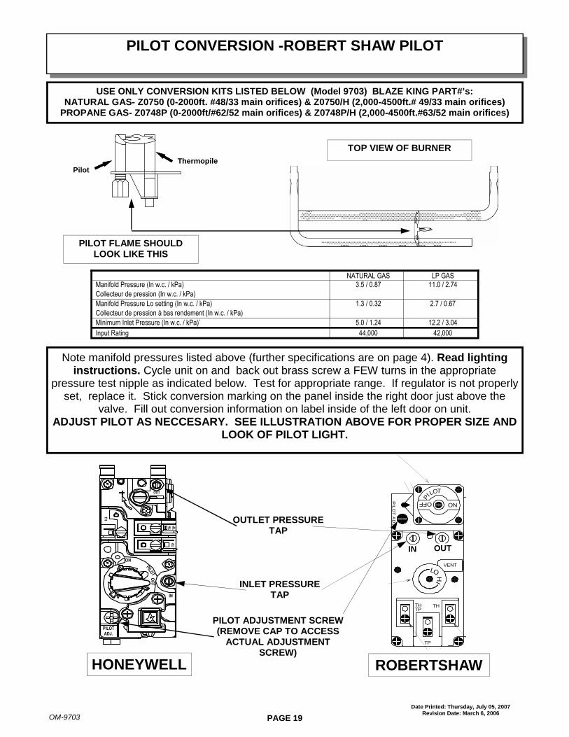
PILOT FLAME SHOULDLOOK LIKE THIS
TOP VIEW OF BURNER
NATURAL GAS LP GASManifold Pressure (In w.c. / kPa) 3.5 / 0.87 11.0 / 2.74
Collecteur de pression (In w.c. / kPa)
Manifold Pressure Lo setting (In w.c. / kPa) 1.3 / 0.32 2.7 / 0.67
Collecteur de pression à bas rendement (In w.c. / kPa)
Minimum Inlet Pressure (In w.c. / kPa)` 5.0 / 1.24 12.2 / 3.04
Input Rating 44,000 42,000
Note manifold pressures listed above (further specifications are on page 4). Read lightinginstructions. Cycle unit on and back out brass screw a FEW turns in the appropriate
pressure test nipple as indicated below. Test for appropriate range. If regulator is not properlyset, replace it. Stick conversion marking on the panel inside the right door just above the
valve. Fill out conversion information on label inside of the left door on unit.ADJUST PILOT AS NECCESARY. SEE ILLUSTRATION ABOVE FOR PROPER SIZE AND
LOOK OF PILOT LIGHT.
OUTLET PRESSURETAP
INLET PRESSURETAP
THTP
TH
TP
LO
HI
VENT
OUTIN
ON
OFFP
ITOL
PIL
OT
AD
J.
IN OUT
HONEYWELL ROBERTSHAW
PILOT ADJUSTMENT SCREW(REMOVE CAP TO ACCESS
ACTUAL ADJUSTMENTSCREW)
PILOT CONVERSION -ROBERT SHAW PILOT
USE ONLY CONVERSION KITS LISTED BELOW (Model 9703) BLAZE KING PART#’s:NATURAL GAS- Z0750 (0-2000ft. #48/33 main orifices) & Z0750/H (2,000-4500ft.# 49/33 main orifices)
PROPANE GAS- Z0748P (0-2000ft/#62/52 main orifices) & Z0748P/H (2,000-4500ft.#63/52 main orifices)
ThermopilePilot
PILOTADJ.
IN
ON
TH TP
TP
TH
OUT
PILOT
OFF
PAGE 20OM-9703
Date Printed: Thursday, July 05, 2007Revision Date: March 6, 2006
FOR YOUR SAFETY - READ BEFORE LIGHTINGWARNING - If you do not follow these instructions exactly, a fire or explosion may result
causing property damage or personal injury.
A. This appliance has a pilot that is lit with a push button Piezo lighter. When lighting the pilot, follow theseinstructions exactly.
B. BEFORE LIGHTING smell all around the appliance area for gas. Be sure to smell next to the floor becausesome gas is heavier than air and will settle on the floor.
WHAT TO DO IF YOU SMELL GAS:
OPEN WINDOWS
DO NOT TOUCH ANY ELECTRIC SWITCH; DO NOT USE ANY PHONE IN YOUR BUILDING
EXTINGUISH ANY OPEN FLAME
IMMEDIATELY CALL YOUR GAS SUPPLIER FROM A NEIGHBOR'S PHONE AND FOLLOW THEGAS SUPPLIER’S INSTRUCTIONS
IF YOU CANNOT REACH YOUR GAS SUPPLIER, CALL THE FIRE DEPARTMENT
C. Never use tools to turn or push any control knobs or switches. If any controls on your appliance (knobs,switches, buttons, dials) fail to move or operate properly do not force them. Excessive force or the use of toolson these controls may damage them and could result in a fire or explosion. If you have a problem do not tryto repair it. Call a qualified service technician.
D. Do not use this appliance if any part has been under water. Immediately call a qualified service technician toinspect the appliance and replace any part of the control system or gas control which has been under water.
LIGHTING PREPARATION
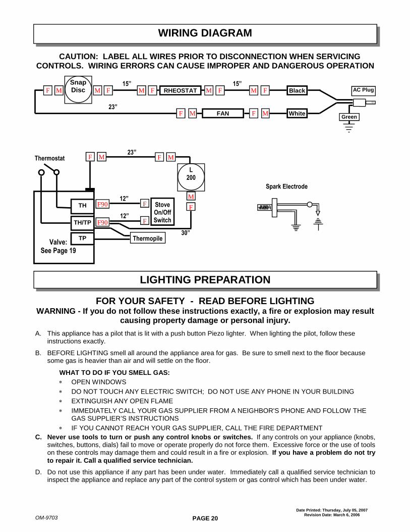
WIRING DIAGRAM
CAUTION: LABEL ALL WIRES PRIOR TO DISCONNECTION WHEN SERVICINGCONTROLS. WIRING ERRORS CAN CAUSE IMPROPER AND DANGEROUS OPERATION
Spark Electrode
RHEOSTATF M M F
MGreen
SnapDiscM MF F
F
AC PlugM F
FAN White
Black
MF
15”15”
23”
Thermopile
Thermostat
StoveOn/OffSwitch
Valve:See Page 19
TP
TH
TH/TP
FF90
F90 F
L200
M
F
MF
12”
12”
23”
30”
MF

PAGE 21OM-9703
Date Printed: Thursday, July 05, 2007Revision Date: March 6, 2006
1. STOP! Read the safety information on the previous page.2. Controls are accessed by opening the right side door panel.3. Set the optional wall thermostat to lowest setting or switch the Stove On/Off Switch to the off position.4. Push in the gas control knob slightly and turn clockwise to OFF.
NOTE: The knob cannot be turned from PILOT to OFF unless the knob is pushed in slightly. DO NOT FORCE.5. Wait five (5) minutes to clear out any gas. If you smell gas STOP! Follow step B in the safety information
section on the previous page. If you do not smell gas, go the step 7.6. Turn Control Knob counter clockwise to PILOT position.7. Depress control knob and push in the Piezo ignitor button. Once pilot ignites, continue to hold the control knob
in for about one (1) minute.Release the knob and it will pop back up. Pilot should remain lit. If it goes out,repeat from step 5. If the knob does not pop up when released, stop and immediately call your service technician or gas
supplier. If the pilot will not stay lit after several tries, turn the gas control knob to OFF and call your service
technician or gas supplier.8. Turn the gas control knob counter clockwise to ON. Turn on all electric power to the appliance. Set the
thermostat to desired setting, or if you are not using the thermostat, switch the Stove On/Off Switch to the onposition.
NOTE: IF THERMOSTAT IS TO BE USED, THE STOVE ON/OFF SWITCH SHOULD BE IN THE OFF POSITION.IF SWITCH IS LEFT ON, THE STOVE WILL CONTINUE TO RUN AND THE THERMOSTAT WILL HAVE NOEFFECT.
NOTE: Fan operation is controlled by the temperature of the stove. It will turn on after the stove reachesapproximately 130 degrees F and will run after the stove is turned off until it cools down.
TO TURN OFF GAS APPLIANCE:8. Set the thermostat to lowest setting or if you are not using the thermostat then switch the Stove On/Off Switch
to the off position9. Push in the gas control knob slightly and turn clockwise to OFF. DO NOT FORCE.10. Turn off all electric power to the appliance if a service is to be performed.
LIGHTING INSTRUCTIONS
PILOTADJ.
IN
ON
TH TP
TP
TH
OUT
PILOT
OFF TH
TPTH
TP
LO
HI
VENT
OUTIN
ON
OFFPITOL
PIL
OT
AD
J.
OFF
ON
Pilot Line
Piezo PushButton Ignitor
StoveOn/OffSwitch
Connect ToThermostat
ControlValve
ManifoldTestingAccess
Hi/ LowFlameControl
Knob
ControlKnob
ManifoldTestingAccess
Piezo PushButton Ignitor
Connect ToThermostat
Connect ToThermostat
ManifoldTestingAccess

PAGE 22OM-9703
Date Printed: Thursday, July 05, 2007Revision Date: March 6, 2006
9703 - REPLACEMENT PARTS LIST
PART NAME: PART #1. Robertshaw Gas Valve 0718A
Honeywell Gas Valve 07202. Fan 0719B3. Main Burner Switch 0725A4/5/6. Log Set (3 piece) 08137. Piezzo Push Button Igniter 07378. Shroud Trim Long (Insert only) 0758B
“ “ Short “ 07679. Fiber Embers 0745
10. Fan Cord Z015811. Front Decor - Gold Z9732G12. Pedestal 974813. Main Gas Line 3/8”x12” Flex 0838B14. Pilot Line 1/4”x30” Flex 0839D15. Front Burner Gas Line 36” Flex 0838C16. PSE Pilot Assembly. OBSOLETE
Use Robert Shaw (Abrev. RS)17. Robert Shaw-Pilot Hood
c/w Orifice & Electrode 0721VC18. Robert Shaw Electrode
c/w 24” Wire 0738B19. Thermopile Generator; use with
Robert Shaw or PSE 0721A20. LPG Kit: 0-2000ft Z0748P21. LPG Kit: 2000-4500ft Z0748P/H22. Nat Regulator (RS) 074723. LPG Regulator (RS) 0734
INSERT
1. Remove 7/8” gasket2. Using a nut driver remove all 14 6/32 nuts and washers from around the door3. Before removing glass retainers note there are two different retainers. One for the bottom and one for the top. The top
retainer has a long notch across the bottom of it and the bottom retainer is one solid piece. It is important to make sure thatthe top retainer is used for the top of the door. If it is not it will void your warranty on the door.
4. Remove glass retainers (4)5. Remove 2 seal plates from frame of door.6. Remove channel tape from around 3 pieces glass7. Remove gold door from work area and completely clean all debris to prevent gold door from being scratched.8. Place new glass flat and allow approx. 1/8” space between outside pieces and center.9. Starting at a corner and using channel tape (5/8”) , peel backing off of tape and in small sections at a time, wrap around the outer
edges of glass making sure spaces are equal between outer glass and center (1/8”).10. Taking gold door place seal plates onto the two bends of the door making sure to center evenly.11. Place glass into frame of gold door make sure to center spaces with the bend of the door where seal plates are aligned.12. Clean glass retainers of all residue. Place bottom retainer in proper section and top retainer in top part of door. Next, place two outside
retainers on door.13. When applying nuts and washers start in center of either top or bottom retainer and work your way out. This should allow for easier
application. Do not tighten nuts until all are on and centering of glass and retainers is adequate. Do not over tighten.14. Apply cement in small fine line around the inside ledge of glass retainers.15. Starting between the door hinges put new 7/8 gasket on, pressing it into the corners and bends of the door. Cut gasket 1/8” from end
and push into closing end. Press gasket securely into place.
PART NAME: PART #24. Rheostat (fan speed control) Z0136A25. F200 Snap Disc (Fan Switch) 1144B26. L200 Snap Disc (Spill Switch) 114327. Wall Thermostat 0736
Glass Replacement Procedure