product manualturnstiles.us/pdf/catrax plus manual_05.pdf product manual * 8641 s. warhawk rd. *...
TRANSCRIPT
www.TURNSTILES.us PRODUCT MANUAL
www.TURNSTILES.Tel: 303 670 1099 ext 11 *
us * 8641 S.Fax: 303 679
Warhawk Rd. * Conifer, CO 80433 8949 * email: [email protected]

Product Manual
3
INDEX
1 GUIDELINES ................................................................................................ 4
2 INTRODUCTION........................................................................................... 4
3 CHARACTERISTICS ...................................................................................... 4
3.1 CATRAX Plus operating mechanisms............................................................ 6
4 CATRAX PLUS ASSEMBLY / INSTALLATION ................................................. 6
4.1 Visual inspection ...................................................................................... 6
4.2 Preparing the installation site..................................................................... 7
4.3 Installing the column ................................................................................ 7
4.4 Mounting of arms and covers ..................................................................... 8
4.5 Access to the CATRAX Plus internal components after assembly ..................... 9
5 INSTALLATION/ASSEMBLY OF OPTIONAL PRODUCTS ................................. 9
5.1 Card collection kit with chute ..................................................................... 9
5.1.1 Connecting the card collection box to the control board ..................... 10
5.2 Pictogram kit ......................................................................................... 10
5.3 Counter................................................................................................. 11
5.4 Power supply ......................................................................................... 11
5.5 Control board ........................................................................................ 12
5.5.1 Inputs ......................................................................................... 13
5.5.2 Outputs ....................................................................................... 14
5.5.3 Control board configuration – Dip Switch 1....................................... 16
5.5.4 Configuration examples ................................................................. 16
5.6 No-break power unit............................................................................... 16
5.6.1 Anti-panic device .......................................................................... 17
5.7 Display ................................................................................................. 17
5.7.1 Display configuration and operation via software .............................. 18
5.7.2 Adjusting the display manually ....................................................... 20
5.7.3 Connection table........................................................................... 21
6 MAINTENANCE........................................................................................... 21
6.1 Preventive and corrective maintenance procedures..................................... 21
6.2 Troubleshooting ..................................................................................... 23
7 TECHNICAL CHARACTERISTICS ................................................................. 23
8 WARRANTY AND TECHNICAL ASSISTANCE ................................................ 25
Product Manual
4
1 GUIDELINES
ı Carefully read the instructions contained in this manual before assembling andinstalling the Catrax Plus turnstile. This will extend the life of the product and willenable you to fully benefit from all its features.
ı This product was not designed for outdoor use in unprotected areas.
ı Retain this manual for future reference.
ı Digicon reserves the right to upgrade the characteristics of its products at any timein order to incorporate technological advancements.
ı Digicon reserves the right to change the information contained in this manualwithout notice.
ı Digicon does not provide any warranty related to the information contained in thismanual. Digicon cannot be held responsible for any errors this manual may containor for any problems caused by its use.
ı The information contained in this manual is the exclusive property of Digicon and isprotected by copyright laws.
ı This manual may not be copied, photocopied or translated in its entirety or in part,in any kind of medium, without Digicon’s written permission.
2 INTRODUCTION
The CATRAX line of turnstiles was developed to be robust, reliable and estheticallypleasing. Its rounded lines house a sturdy blocking mechanism designed for very lowmaintenance.
CATRAX Plus serves all major access control technologies presently available, beingacclaimed as the best option in turnstiles in the market.
This manual presents a detailed description of CATRAX Plus operation andcomponents. To get to know other Digicon products, please visit our website atwww.digicon.com.br or www.catrax.com.br.
3 CHARACTERISTICS
The CATRAX Plus is a column-type mini turnstile with three bidirectional arms finishedwith brushed stainless steel (AISI 304).
Product Manual
5
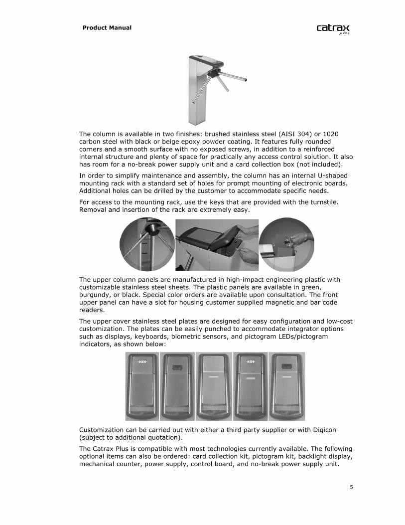
The column is available in two finishes: brushed stainless steel (AISI 304) or 1020carbon steel with black or beige epoxy powder coating. It features fully roundedcorners and a smooth surface with no exposed screws, in addition to a reinforcedinternal structure and plenty of space for practically any access control solution. It alsohas room for a no-break power supply unit and a card collection box (not included).
In order to simplify maintenance and assembly, the column has an internal U-shapedmounting rack with a standard set of holes for prompt mounting of electronic boards.Additional holes can be drilled by the customer to accommodate specific needs.
For access to the mounting rack, use the keys that are provided with the turnstile.Removal and insertion of the rack are extremely easy.
The upper column panels are manufactured in high-impact engineering plastic withcustomizable stainless steel sheets. The plastic panels are available in green,burgundy, or black. Special color orders are available upon consultation. The frontupper panel can have a slot for housing customer supplied magnetic and bar codereaders.
The upper cover stainless steel plates are designed for easy configuration and low-costcustomization. The plates can be easily punched to accommodate integrator optionssuch as displays, keyboards, biometric sensors, and pictogram LEDs/pictogramindicators, as shown below:
Customization can be carried out with either a third party supplier or with Digicon(subject to additional quotation).
The Catrax Plus is compatible with most technologies currently available. The followingoptional items can also be ordered: card collection kit, pictogram kit, backlight display,mechanical counter, power supply, control board, and no-break power supply unit.
Product Manual
6
These options will be described in greater detail in section 5 Installation/Assembly ofoptional products.
NOTEFor detailed information on the dimensions of CATRAX Plus components, seesection 7 Technical Characteristics, page 23.
3.1 CATRAX PLUS OPERATING MECHANISMS
The CATRAX Plus features two operating mechanisms. The basic model (with nocontrol board) employs a bidirectional rotation system with two 12 V electromagnetsthat activate the locks and two optical sensors that provide the electromagnets withinformation on turn completion and direction of turn.
An optional microprocessor-based control board is also available. In this case, an“enable turn” signal is sent. If this signal is recognized, the arm will turn from left toright or right to left depending on the signal received. Once half the turn (60 degrees)is completed, a 400 ms return signal is emitted informing the direction of turn. Afterthis signal, the arm will not turn back.
Depending on the turnstile’s configuration and model, forcing the arm in the absenceof an “enable turn” signal will activate an electromagnet that locks the arm. In thiscase, the equipment may also emit an audible alarm and/or display a red X on theupper panel display (models with pictogram indicators). A return signal will then besent, indicating that the turnstile was forced and informing the direction of turn.
CAUTIONThe specifications described above refer to optional items manufactured byDigicon. However, products from other manufacturers may also be installed onthe CATRAX Plus basic model (including control boards).
4 CATRAX PLUS ASSEMBLY / INSTALLATION
4.1 VISUAL INSPECTION
Depending on the customer’s order the CATRAX Plus may include items that are notfactory-installed. It is very important to carry out a careful visual inspection of thecontents before beginning assembly and installation. Contents should be comparedwith the checklist provided with the package.
CAUTIONIn order to prevent the loss of access keys, bolts and spanners used to assemblethe CATRAX Plus, these items are taped to the box containing the arms. Beforedisposing of any wrapping materials (plastic or cardboard), make sure that youhave identified all the items in the checklist.
Product Manual
7
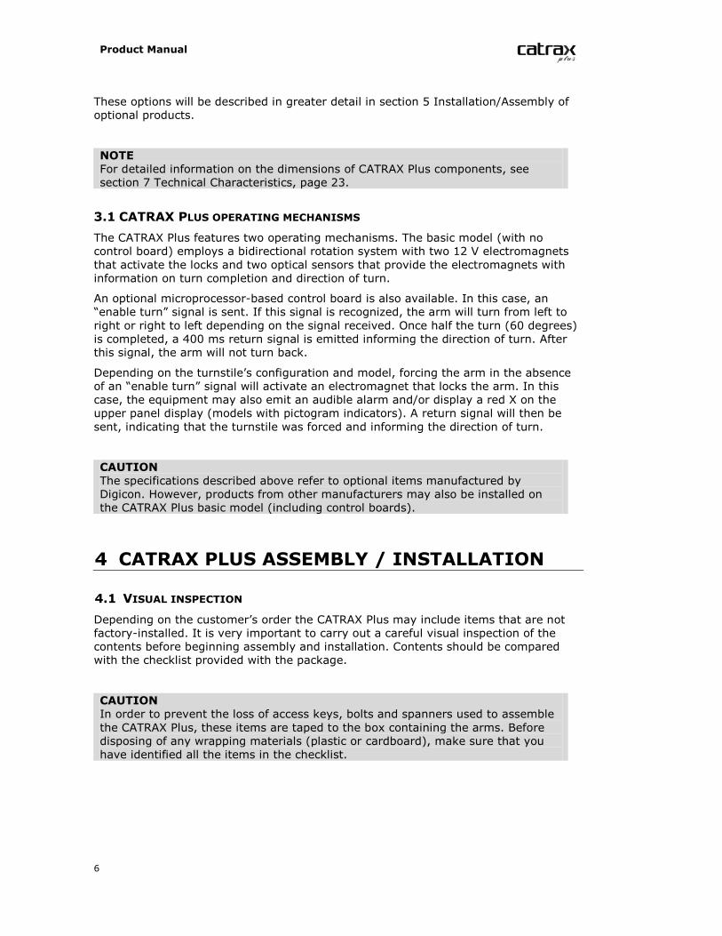
The figure below shows all the parts that may come with your CATRAX Plus:
NOTEIn addition to the items indicated above, the CATRAX Plus may include an optionalcounter, a power supply unit, a control board, a no-break power unit, and apictogram kit.
4.2 PREPARING THE INSTALLATION SITE
Before installing CATRAX Plus, please verify that:
1. The site chosen for installation is adequate – keep in mind that the turnstile mustbe installed indoors.
2. There is an energy source or electric outlet close to where the turnstile will beinstalled.
4. There is enough room (at least 5 cm) between the rear part of the CATRAX Pluscolumn and the wall. This is important to ensure access to the upper panel and rearcable access panel.
5. There is enough room for the arms to turn. For additional details concerningequipment dimensions, see item 7 Technical Characteristics, page 23.
6. The floor has the necessary support structure for anchor bolts (suggested minimumof 4 cm of FCK15 MPa concrete or equivalent).
4.3 INSTALLING THE COLUMN
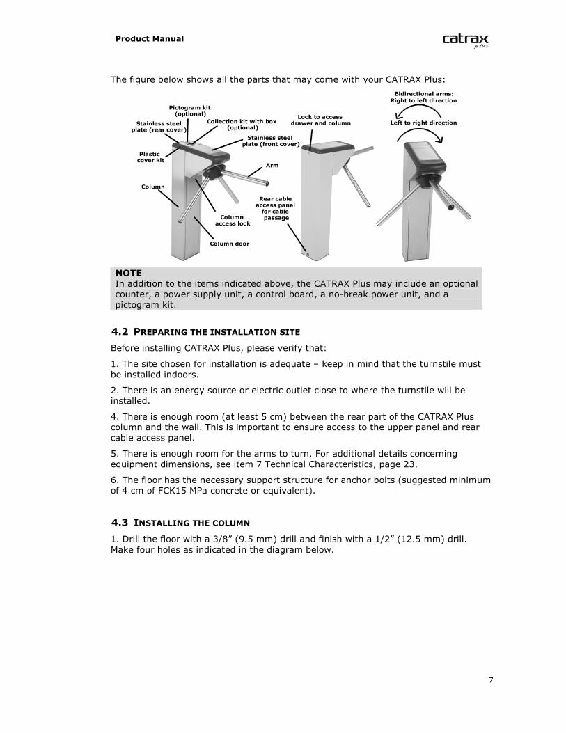
1. Drill the floor with a 3/8” (9.5 mm) drill and finish with a 1/2” (12.5 mm) drill.Make four holes as indicated in the diagram below.
Product Manual
8
Dimensions in mm.
NOTEElectrical and communication cables must pass through the cable exit. Check cut-out dimensions to make sure all cables will fit.
NOTEA heavy-duty steel template for installation of the column may be purchased fromDigicon.
2. Clean the holes, removing drilling residues.
3. Place the four anchor bolts in the holes, leaving approximately 25 mm of the anchorbolt out of the hole.
NOTERecommended bolts: Tecmart AF38110, 3/8x4”.
4. Position the column and fasten it onto the floor with the four bolts that come withthe anchor bolts. Use a 3/4” socket wrench or spanner.
4.4 MOUNTING OF ARMS AND COVERS
After installing the column, you may proceed with mounting the arms and plasticcovers.
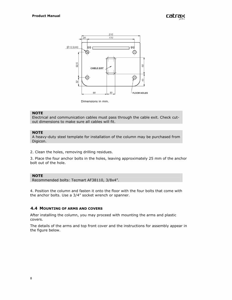
The details of the arms and top front cover and the instructions for assembly appear inthe figure below.
Product Manual
9
NOTEUse a #5 Allen wrench to mount the CATRAX Plus.
After that, mount the upper panel rear cover. The following figure shows the cover indetail.
4.5 ACCESS TO THE CATRAX PLUS INTERNAL COMPONENTS AFTER ASSEMBLY
After the CATRAX Plus has been installed and assembled, access to internalcomponents is possible via the rear cover, the front cover, or the column door, usingthe access keys that come with the equipment.
5 INSTALLATION/ASSEMBLY OF OPTIONALPRODUCTS
Digicon offers several options to enhance access control and facilitate customization.
5.1 CARD COLLECTION KIT WITH CHUTE
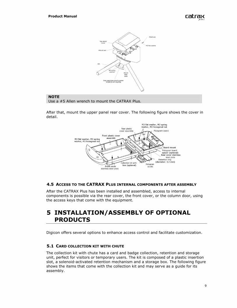
The collection kit with chute has a card and badge collection, retention and storageunit, perfect for visitors or temporary users. The kit is composed of a plastic insertionslot, a solenoid-activated retention mechanism and a storage box. The following figureshows the items that come with the collection kit and may serve as a guide for itsassembly.
Product Manual
10
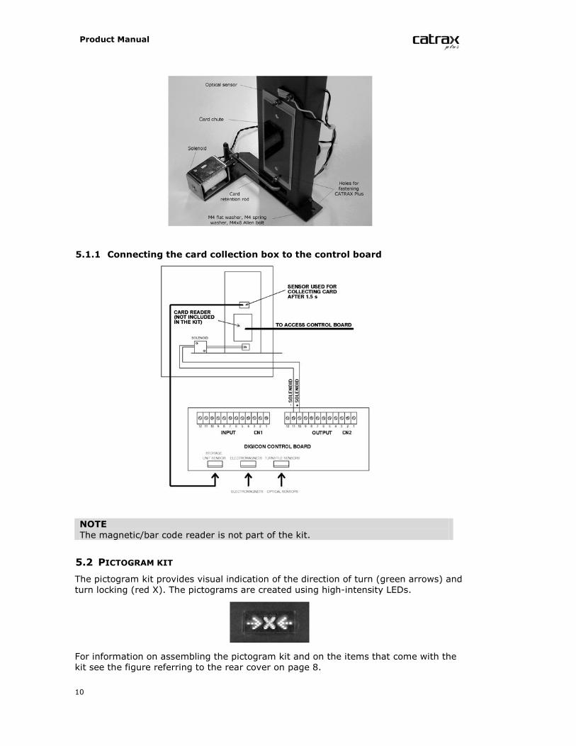
5.1.1 Connecting the card collection box to the control board
NOTEThe magnetic/bar code reader is not part of the kit.
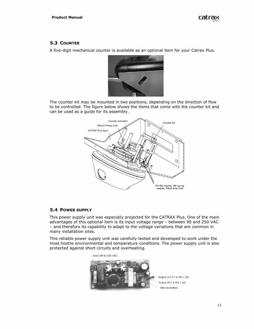
5.2 PICTOGRAM KIT
The pictogram kit provides visual indication of the direction of turn (green arrows) andturn locking (red X). The pictograms are created using high-intensity LEDs.
For information on assembling the pictogram kit and on the items that come with thekit see the figure referring to the rear cover on page 8.
Product Manual
11
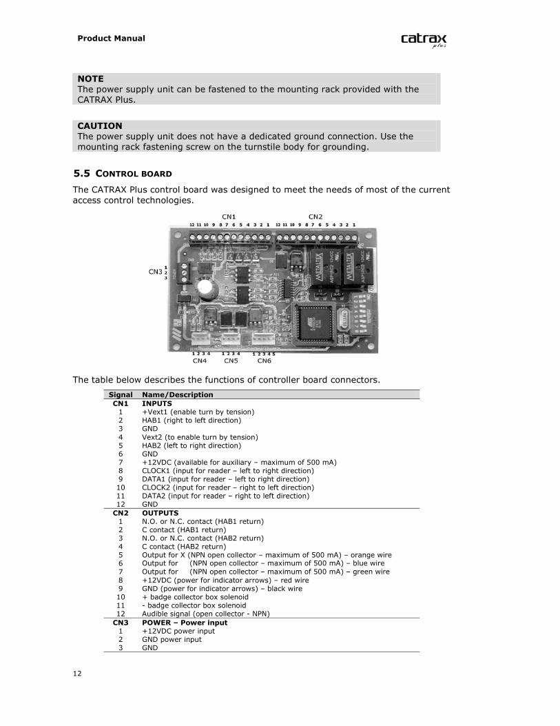
5.3 COUNTER
A five-digit mechanical counter is available as an optional item for your Catrax Plus.
The counter kit may be mounted in two positions, depending on the direction of flowto be controlled. The figure below shows the items that come with the counter kit andcan be used as a guide for its assembly.
5.4 POWER SUPPLY
This power supply unit was especially projected for the CATRAX Plus. One of the mainadvantages of this optional item is its input voltage range – between 90 and 250 VAC– and therefore its capability to adapt to the voltage variations that are common inmany installation sites.
This reliable power supply unit was carefully tested and developed to work under themost hostile environmental and temperature conditions. The power supply unit is alsoprotected against short circuits and overheating.
Product Manual
12
NOTEThe power supply unit can be fastened to the mounting rack provided with theCATRAX Plus.
CAUTIONThe power supply unit does not have a dedicated ground connection. Use themounting rack fastening screw on the turnstile body for grounding.
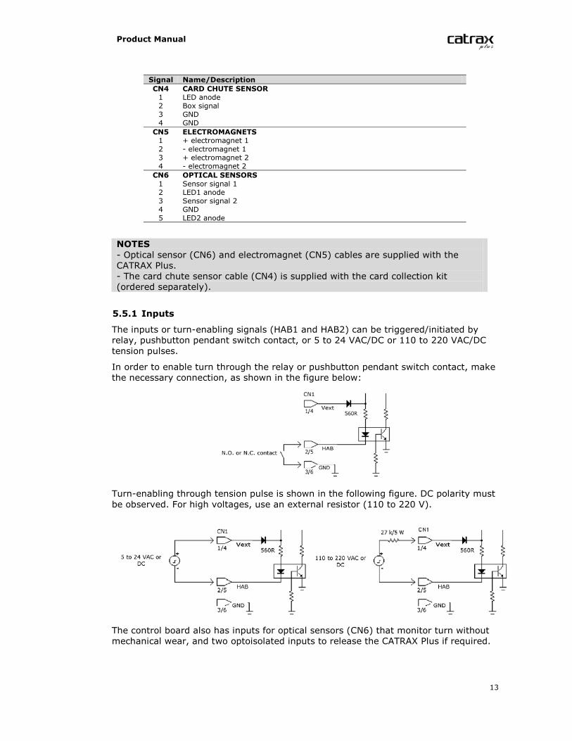
5.5 CONTROL BOARD
The CATRAX Plus control board was designed to meet the needs of most of the currentaccess control technologies.
The table below describes the functions of controller board connectors.
Signal Name/DescriptionCN1 INPUTS1 +Vext1 (enable turn by tension)2 HAB1 (right to left direction)3 GND4 Vext2 (to enable turn by tension)5 HAB2 (left to right direction)6 GND7 +12VDC (available for auxiliary – maximum of 500 mA)8 CLOCK1 (input for reader – left to right direction)9 DATA1 (input for reader – left to right direction)10 CLOCK2 (input for reader – right to left direction)11 DATA2 (input for reader – right to left direction)12 GNDCN2 OUTPUTS1 N.O. or N.C. contact (HAB1 return)2 C contact (HAB1 return)3 N.O. or N.C. contact (HAB2 return)4 C contact (HAB2 return)5 Output for X (NPN open collector – maximum of 500 mA) – orange wire6 Output for (NPN open collector – maximum of 500 mA) – blue wire7 Output for (NPN open collector – maximum of 500 mA) – green wire8 +12VDC (power for indicator arrows) – red wire9 GND (power for indicator arrows) – black wire10 + badge collector box solenoid11 - badge collector box solenoid12 Audible signal (open collector - NPN)CN3 POWER – Power input1 +12VDC power input2 GND power input3 GND
Product Manual
13
Signal Name/DescriptionCN4 CARD CHUTE SENSOR1 LED anode2 Box signal3 GND4 GNDCN5 ELECTROMAGNETS1 + electromagnet 12 - electromagnet 13 + electromagnet 24 - electromagnet 2CN6 OPTICAL SENSORS1 Sensor signal 12 LED1 anode3 Sensor signal 24 GND5 LED2 anode
NOTES- Optical sensor (CN6) and electromagnet (CN5) cables are supplied with theCATRAX Plus.- The card chute sensor cable (CN4) is supplied with the card collection kit(ordered separately).
5.5.1 Inputs
The inputs or turn-enabling signals (HAB1 and HAB2) can be triggered/initiated byrelay, pushbutton pendant switch contact, or 5 to 24 VAC/DC or 110 to 220 VAC/DCtension pulses.
In order to enable turn through the relay or pushbutton pendant switch contact, makethe necessary connection, as shown in the figure below:
Turn-enabling through tension pulse is shown in the following figure. DC polarity mustbe observed. For high voltages, use an external resistor (110 to 220 V).
The control board also has inputs for optical sensors (CN6) that monitor turn withoutmechanical wear, and two optoisolated inputs to release the CATRAX Plus if required.
Product Manual
14
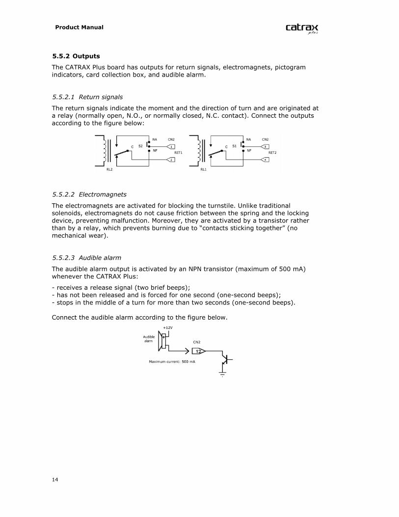
5.5.2 Outputs
The CATRAX Plus board has outputs for return signals, electromagnets, pictogramindicators, card collection box, and audible alarm.
5.5.2.1 Return signals
The return signals indicate the moment and the direction of turn and are originated ata relay (normally open, N.O., or normally closed, N.C. contact). Connect the outputsaccording to the figure below:
5.5.2.2 Electromagnets
The electromagnets are activated for blocking the turnstile. Unlike traditionalsolenoids, electromagnets do not cause friction between the spring and the lockingdevice, preventing malfunction. Moreover, they are activated by a transistor ratherthan by a relay, which prevents burning due to “contacts sticking together” (nomechanical wear).
5.5.2.3 Audible alarm
The audible alarm output is activated by an NPN transistor (maximum of 500 mA)whenever the CATRAX Plus:
- receives a release signal (two brief beeps);- has not been released and is forced for one second (one-second beeps);- stops in the middle of a turn for more than two seconds (one-second beeps).
Connect the audible alarm according to the figure below.
Product Manual
15
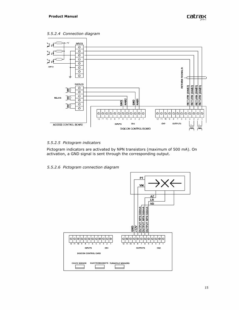
5.5.2.4 Connection diagram
5.5.2.5 Pictogram indicators
Pictogram indicators are activated by NPN transistors (maximum of 500 mA). Onactivation, a GND signal is sent through the corresponding output.
5.5.2.6 Pictogram connection diagram
Product Manual
16
5.5.3 Control board configuration – Dip Switch 1
DS 1 is used to configure the following:
- direction of turn;- maximum time of passage;- N.O. inputs (normally open relay or pushbutton pendant switch contacts withoutinput tension) to enable turn in the presence of these signals, or N.C. inputs (normallyclosed relay or pushbutton pendant switch contacts with input tension) to enable turnin the absence of these signals;- audible alarm signal if the turnstile stops in mid turn for over two seconds.
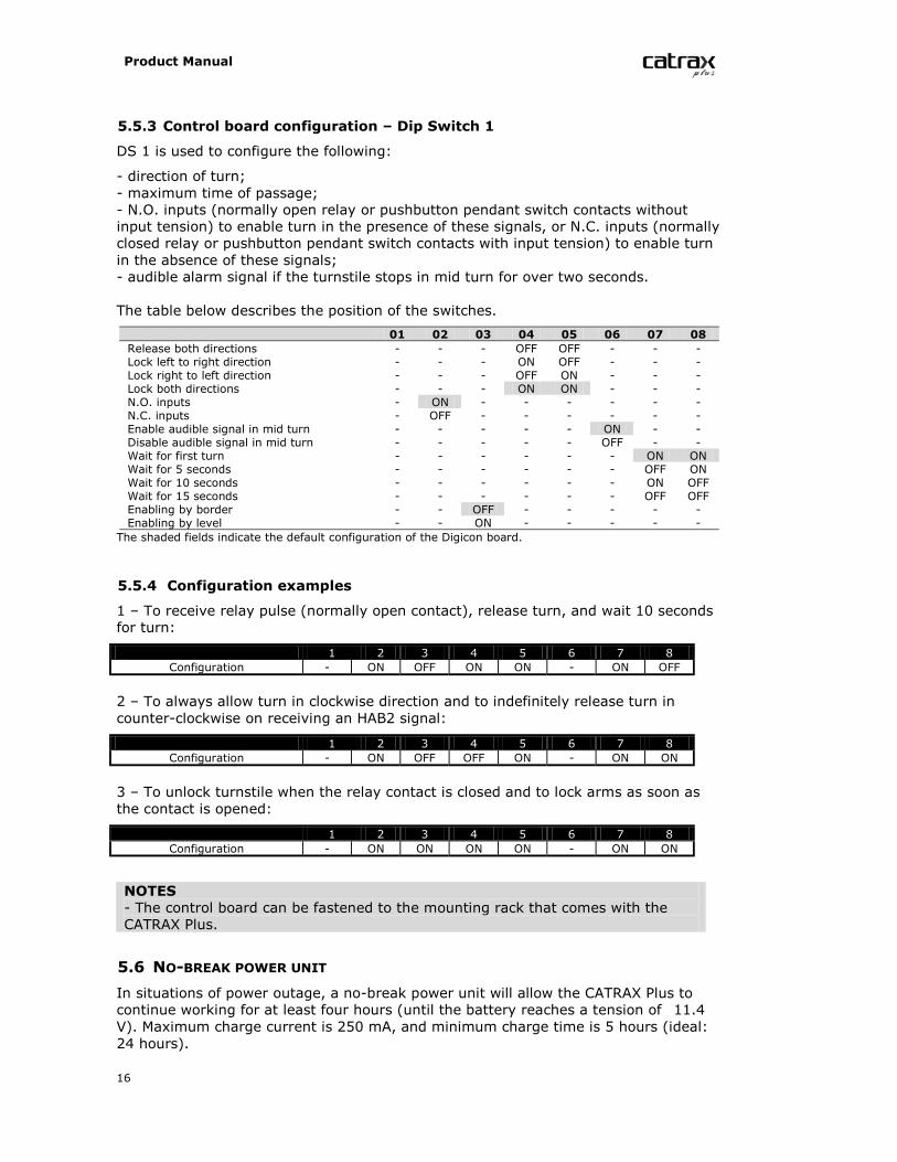
The table below describes the position of the switches.
01 02 03 04 05 06 07 08Release both directions - - - OFF OFF - - -Lock left to right direction - - - ON OFF - - -Lock right to left direction - - - OFF ON - - -Lock both directions - - - ON ON - - -N.O. inputs - ON - - - - - -N.C. inputs - OFF - - - - - -Enable audible signal in mid turn - - - - - ON - -Disable audible signal in mid turn - - - - - OFF - -Wait for first turn - - - - - - ON ONWait for 5 seconds - - - - - - OFF ONWait for 10 seconds - - - - - - ON OFFWait for 15 seconds - - - - - - OFF OFFEnabling by border - - OFF - - - - -Enabling by level - - ON - - - - -The shaded fields indicate the default configuration of the Digicon board.
5.5.4 Configuration examples
1 – To receive relay pulse (normally open contact), release turn, and wait 10 secondsfor turn:
1 2 3 4 5 6 7 8Configuration - ON OFF ON ON - ON OFF
2 – To always allow turn in clockwise direction and to indefinitely release turn incounter-clockwise on receiving an HAB2 signal:
1 2 3 4 5 6 7 8Configuration - ON OFF OFF ON - ON ON
3 – To unlock turnstile when the relay contact is closed and to lock arms as soon asthe contact is opened:
1 2 3 4 5 6 7 8Configuration - ON ON ON ON - ON ON
NOTES- The control board can be fastened to the mounting rack that comes with theCATRAX Plus.
5.6 NO-BREAK POWER UNIT
In situations of power outage, a no-break power unit will allow the CATRAX Plus tocontinue working for at least four hours (until the battery reaches a tension of 11.4V). Maximum charge current is 250 mA, and minimum charge time is 5 hours (ideal:24 hours).
Product Manual
17
The no-break kit includes a fastening mount, a sealed 12 V/5 Ah battery, and a board.
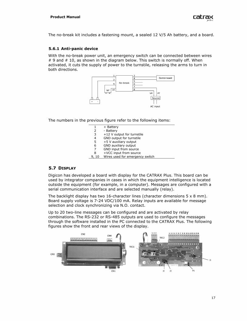
5.6.1 Anti-panic device
With the no-break power unit, an emergency switch can be connected between wires# 9 and # 10, as shown in the diagram below. This switch is normally off. Whenactivated, it cuts the supply of power to the turnstile, releasing the arms to turn inboth directions.
The numbers in the previous figure refer to the following items:
1 + Battery2 - Battery3 +12 V output for turnstile4 GND output for turnstile5 +5 V auxiliary output6 GND auxiliary output7 GND input from source8 +VCC input from source9, 10 Wires used for emergency switch
5.7 DISPLAY
Digicon has developed a board with display for the CATRAX Plus. This board can beused by integrator companies in cases in which the equipment intelligence is locatedoutside the equipment (for example, in a computer). Messages are configured with aserial communication interface and are selected manually (relay).
The backlight display has two 16-character lines (character dimensions 5 x 8 mm).Board supply voltage is 7-24 VDC/100 mA. Relay inputs are available for messageselection and clock synchronizing via N.O. contact.
Up to 20 two-line messages can be configured and are activated by relaycombinations. The RS-232 or RS-485 outputs are used to configure the messagesthrough the software installed in the PC connected to the CATRAX Plus. The followingfigures show the front and rear views of the display.
Product Manual
18
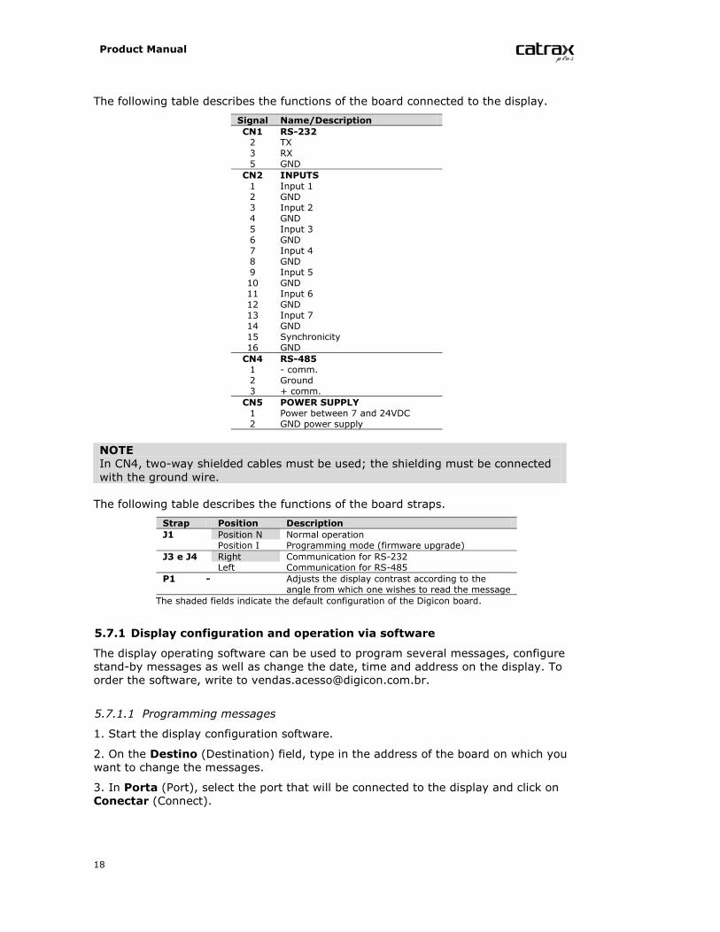
The following table describes the functions of the board connected to the display.
Signal Name/DescriptionCN1 RS-2322 TX3 RX5 GNDCN2 INPUTS1 Input 12 GND3 Input 24 GND5 Input 36 GND7 Input 48 GND9 Input 510 GND11 Input 612 GND13 Input 714 GND15 Synchronicity16 GNDCN4 RS-4851 - comm.2 Ground3 + comm.CN5 POWER SUPPLY1 Power between 7 and 24VDC2 GND power supply
NOTEIn CN4, two-way shielded cables must be used; the shielding must be connectedwith the ground wire.
The following table describes the functions of the board straps.
Strap Position DescriptionJ1 Position N Normal operation
Position I Programming mode (firmware upgrade)J3 e J4 Right Communication for RS-232
Left Communication for RS-485P1 - Adjusts the display contrast according to the
angle from which one wishes to read the messageThe shaded fields indicate the default configuration of the Digicon board.
5.7.1 Display configuration and operation via software
The display operating software can be used to program several messages, configurestand-by messages as well as change the date, time and address on the display. Toorder the software, write to [email protected].
5.7.1.1 Programming messages
1. Start the display configuration software.
2. On the Destino (Destination) field, type in the address of the board on which youwant to change the messages.
3. In Porta (Port), select the port that will be connected to the display and click onConectar (Connect).
Product Manual
19
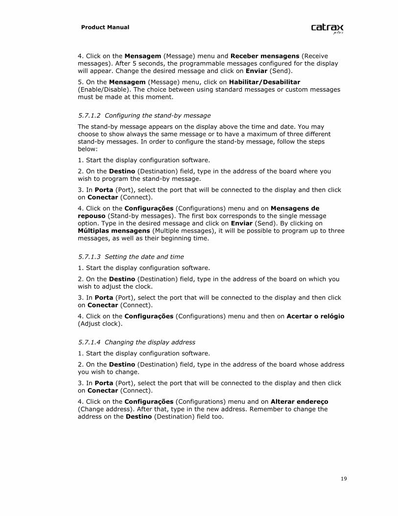
4. Click on the Mensagem (Message) menu and Receber mensagens (Receivemessages). After 5 seconds, the programmable messages configured for the displaywill appear. Change the desired message and click on Enviar (Send).
5. On the Mensagem (Message) menu, click on Habilitar/Desabilitar(Enable/Disable). The choice between using standard messages or custom messagesmust be made at this moment.
5.7.1.2 Configuring the stand-by message
The stand-by message appears on the display above the time and date. You maychoose to show always the same message or to have a maximum of three differentstand-by messages. In order to configure the stand-by message, follow the stepsbelow:
1. Start the display configuration software.
2. On the Destino (Destination) field, type in the address of the board where youwish to program the stand-by message.
3. In Porta (Port), select the port that will be connected to the display and then clickon Conectar (Connect).
4. Click on the Configurações (Configurations) menu and on Mensagens derepouso (Stand-by messages). The first box corresponds to the single messageoption. Type in the desired message and click on Enviar (Send). By clicking onMúltiplas mensagens (Multiple messages), it will be possible to program up to threemessages, as well as their beginning time.
5.7.1.3 Setting the date and time
1. Start the display configuration software.
2. On the Destino (Destination) field, type in the address of the board on which youwish to adjust the clock.
3. In Porta (Port), select the port that will be connected to the display and then clickon Conectar (Connect).
4. Click on the Configurações (Configurations) menu and then on Acertar o relógio(Adjust clock).
5.7.1.4 Changing the display address
1. Start the display configuration software.
2. On the Destino (Destination) field, type in the address of the board whose addressyou wish to change.
3. In Porta (Port), select the port that will be connected to the display and then clickon Conectar (Connect).
4. Click on the Configurações (Configurations) menu and on Alterar endereço(Change address). After that, type in the new address. Remember to change theaddress on the Destino (Destination) field too.
Product Manual
20
5.7.2 Adjusting the display manually
5.7.2.1 Default message selection
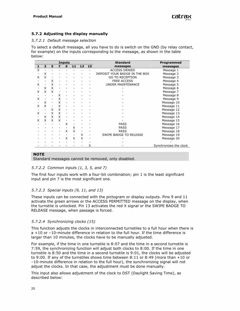
To select a default message, all you have to do is switch on the GND (by relay contact,for example) on the inputs corresponding to the message, as shown in the tablebelow:
Inputs Programmed1 3 5 7 9 11 13 15
Standardmessages messages
X - - - - - - - ACCESS DENIED Message 1- X - - - - - - DEPOSIT YOUR BADGE IN THE BOX Message 2X X - - - - - - GO TO RECEPTION Message 3- - X - - - - - FREE ACCESS Message 4X - X - - - - - UNDER MAINTENANCE Message 5- X X - - - - - - Message 6X X X - - - - - - Message 7- - - X - - - - - Message 8X - - X - - - - - Message 9- X - X - - - - - Message 10X X - X - - - - - Message 11- - X X - - - - - Message 12X - X X - - - - - Message 13- X X X - - - - - Message 14X X X X - - - - - Message 15- - - - X - - - PASS Message 16- - - - - X - - PASS Message 17- - - - X X - - PASS Message 18- - - - - - X - SWIPE BADGE TO RELEASE Message 19- - - - X X X - - Message 20- - - - - - - - - -- - - - - - - X - Synchronizes the clock
NOTEStandard messages cannot be removed, only disabled.
5.7.2.2 Common inputs (1, 3, 5, and 7)
The first four inputs work with a four-bit combination; pin 1 is the least significantinput and pin 7 is the most significant one.
5.7.2.3 Special inputs (9, 11, and 13)
These inputs can be connected with the pictogram or display outputs. Pins 9 and 11activate the green arrows or the ACCESS PERMITTED message on the display, whenthe turnstile is unlocked. Pin 13 activates the red X signal or the SWIPE BADGE TORELEASE message, when passage is forced.
5.7.2.4 Synchronizing clocks (15)
This function adjusts the clocks in interconnected turnstiles to a full hour when there isa +10 or –10-minute difference in relation to the full hour. If the time difference islarger than 10 minutes, the clocks have to be manually adjusted.
For example, if the time in one turnstile is 8:07 and the time in a second turnstile is7:59, the synchronizing function will adjust both clocks to 8:00. If the time in oneturnstile is 8:50 and the time in a second turnstile is 9:01, the clocks will be adjustedto 9:00. If any of the turnstiles shows time between 8:11 or 8:49 (more than +10 or–10-minute difference in relation to the full hour), the synchronizing signal will notadjust the clocks. In that case, the adjustment must be done manually.
This input also allows adjustment of the clock to DST (Daylight Saving Time), asdescribed below:
Product Manual
21
- Up to two-second pulse = synchronizes the clock (rounds up time to full hour);- Two to four-second pulse = sets clock one hour back (end of DST);- Four to six-second pulse = sets clock one hour ahead (beginning of DST).
5.7.2.5 Adjusting date and time manually
In order to adjust the clock manually, press TEC2 – the digits corresponding to timewill blink for 5 seconds. To change the hour, press TEC1 until the desired hourappears, and then press TEC2 to save the setting.
To change the minutes, press TEC2 twice and TEC1 until the desired time appears onthe display; then, press TEC2 to save the setting. If necessary, press TEC2 threetimes to change the day, and so on.
5.7.2.6 Display address
The address that appears on the display can be verified during system initialization orby pressing TEC1.
To adjust the board address manually, press TEC1; the current address will appear forfive seconds. To change the address, press TEC2 and then TEC1 until the desiredaddress appears (maximum: 254). Press TEC2 to save the setting.
NOTEAll the boards are associated with address 255 in addition to a programmedaddress, which may be used, for instance, to change all messages or adjust allclocks at the same time. In the software, all you have to do is send the desiredcommands to address 255; all displays will be changed simultaneously.
5.7.3 Connection table
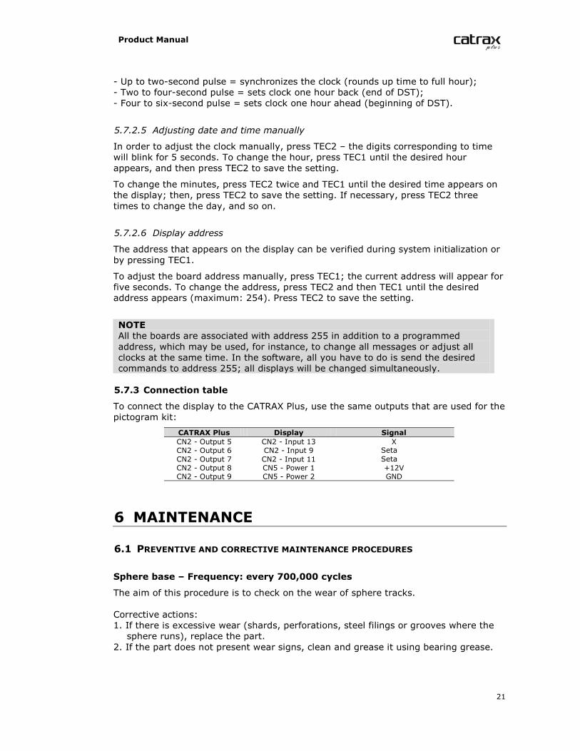
To connect the display to the CATRAX Plus, use the same outputs that are used for thepictogram kit:
CATRAX Plus Display SignalCN2 - Output 5 CN2 - Input 13 XCN2 - Output 6 CN2 - Input 9 SetaCN2 - Output 7 CN2 - Input 11 SetaCN2 - Output 8 CN5 - Power 1 +12VCN2 - Output 9 CN5 - Power 2 GND
6 MAINTENANCE
6.1 PREVENTIVE AND CORRECTIVE MAINTENANCE PROCEDURES
Sphere base – Frequency: every 700,000 cycles
The aim of this procedure is to check on the wear of sphere tracks.
Corrective actions:1. If there is excessive wear (shards, perforations, steel filings or grooves where thesphere runs), replace the part.
2. If the part does not present wear signs, clean and grease it using bearing grease.
Product Manual
22
Optical sensors – Frequency: at least once a year (depending onenvironmental conditions)
This maintenance procedure requires the use of a multimeter. In order to verify theneed for corrective actions, it is necessary to measure [the?] CN6 when the turnstile ispowered, according to the instructions below:- Set the multimeter to measure DC voltage of up to 20 V. Next, clamp the blackpointer to pin 4 and the red pointer to pin 1 of CN6. Voltage should be lower than 0.8V (non-obstructed sensors). With the pointers in the same position, force theequipment arms in both directions (in one of the directions, the voltage measured bythe multimeter should be higher than 4.5 V).- Repeat the operation clamping the black pointer to pin 4 and the red pointer to pin3. The results should be the same as those obtained with pins 4 and 1.- Verify if the sensors present signs of dust.
Corrective actions:1. If the measurements do not match the standards described above, replace thesensor.
2. Clean the sensors using a clean brush.
NOTEIn excessively dusty environments, perform this maintenance cleaning proceduremore than once a year.
Electromagnets - Frequency: every 700,000 cycles
This maintenance procedure requires the use of a multimeter. Disconnect the CN3from the control board and verify the resistance of the electromagnets. The valueshould be between 12.5 and 13.5 ohms on pins 1, 2, 3, and 4 of the electromagnetconnector. Once the measurement is complete, CN3 should be connected to the boardagain.
Corrective actions:1. Replace the electromagnet if one of the following conditions is observed: incorrectresistance, electromagnet in short-circuit or open.
2. If the electromagnet is not working, verify the board and the tension.3. Tighten the bolts on the base if the electromagnet is lose.
Electromagnet adjustment (if necessary):1. Force the lock against the sprocket and the equipment arm until the lock is totallyinside the first tooth (until the arm is locked).
2. Next, release the fastening bolts and press the electromagnet against the lockbuffer so that all its area gets in contact with the electromagnet.
3. Tighten the bolts again.
Lock assembly – Frequency: every 700,000 cycles
In order to verify the need for corrective actions, you should:- Verify the correct lock position.- Check whether the lock is fitted to the sprocket or whether there is apparent wear.
Corrective actions:1. If the lock is incorrectly positioned, verify the retention ring and the spring thattensions the assembly.
2. If the lock is not fitted to the sprocket, replace the lock or the sprocket.3. If there are signs of wear on the lock end, replace the lock.
Product Manual
23
Sprocket assembly – Frequency: every 700,000 cycles
To verify the need for corrective actions, you should:- Verify the wear of the sprocket teeth.- Check the backlash between the central shaft, the sprocket and the cotter pin.
Corrective actions:1. If you observe any signs of wear on the teeth, replace the sprocket.2. If you notice excess backlash between the sprocket and the shaft/cotter pinassembly, replace the sprocket or the cotter pin. To change the cotter pin, use apulley puller.
6.2 TROUBLESHOOTING
Defect Possible cause Actionı CATRAX Plus will notturn on
ı Power supply cable is not connectedproperly.
ı Power supply fuse is burnt.
ı Verify wires and fuse (fuse: 3A).
ı CATRAX Plus is locked ı Optical sensors are obstructed ordefective.
ı Carry out preventivemaintenance procedures inthe sensors or contactTechnical Assistance.
ı CATRAX Plus will notactivate electromagnet(turnstile cannot belocked)
ı The cable is broken or the distancebetween the electromagnet and the lockdevice is inadequately adjusted.
ı Adjust the electromagnet ordeliver the equipment toTechnical Assistance.
ı The arm will not stay inthe correct position.
ı The base of the sphere is worn, dirty,not properly lubricated, or the spring isbroken.
ı Request replacement ofdefective part or contactTechnical Assistance.
ı CATRAX Plus will notlock on the first tooth.
ı The distance between the electromagnetand the lock device is not well adjusted.
ı Adjust the electromagnet orcontact Technical Assistance.
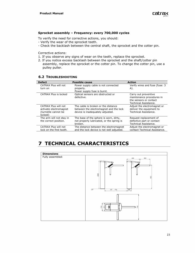
7 TECHNICAL CHARACTERISTICS
DimensionsFully assembled:
Product Manual
24
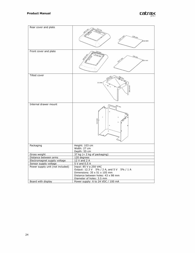
Rear cover and plate
Front cover and plate
Tilted cover
Internal drawer mount
Packaging Height: 103 cmWidth: 27 cmDepth: 55 cm
Gross weight 37 kg (+ 2 kg of packaging)Distance between arms 120 degreesElectromagnet supply voltage 12 V and 2 ASensor supply voltage 5 V and 0.5 APower supply unit (not included) Input: 85 V a 250 VAC
Output: 12.3 V 5% / 2 A, and 5 V 5% / 1 ADimensions: 35 x 51 x 105 mmDistance between holes: 43 x 98 mmDiameter of holes: 3.5 mm
Board with display Power supply: 6 to 24 VDC / 100 mA

Product Manual
25

Product Manual
26


www.TURNSTILES.us * 8641 S. Warhawk Rd. * Conifer, CO 80433Tel: 303 670 1099 ext 11 * Fax: 303 679 8949 * email: [email protected]