micropiles for the replacement of timber … australian small bridges conference 1 micropiles for...
TRANSCRIPT
8th Australian Small Bridges Conference
1
MICROPILES FOR THE REPLACEMENT OF TIMBER RAILWAY BRIDGES – CASE STUDY
Lukasz Gawlik, Design Engineer, Keller, Sydney, [email protected]
The replacement of two timber bridges was accomplished with the application of groups of micropiles to strengthen existing footings and provide the necessary foundations for the new bridge structures. Vertical and inclined micropiles were required. Several technical and practical constraints needed to be addressed to ensure the micropiles were constructed in a safe manner. A limited headroom drill rig was utilised for the works beneath the existing tracks, while an excavator-mounted unit facilitated drilling between the tracks. Design and installation issues and micropile testing are also discussed, and the paper outlines the challenging geotechnical conditions, the drilling techniques adopted and the details of the high capacity micropiles.
INTRODUCTION
Keller was appointed to design and construct micropile solutions for two timber bridge replacements at Rosewood and Sadliers Crossing in Queensland, as part of the Queensland Rail’ infrastructure upgrade.
The new foundations of the bridges were designed considering flooding and scour which had previously caused damage to the bridges resulting in speed limits being introduced.
All the construction works, including micropiling, were to be carried out around the existing bridges while the tracks were live.
The micropile construction programme was extremely tight, allowing for only three (Rosewood) and two (Sadliers Crossing) night shut-downs in order to perform micropiling works in between the track lines. In addition, a low headroom drilling rig was required to install the micropiles in between the existing piers and under the existing bridge spans.
This paper deals with a number of design and construction issues encountered and successfully overcome on both projects.
GEOTECHNICAL CONDITIONS
Geotechnical investigations were carried out for both bridges by the geotechnical consultant, showing quite different soil and rock conditions at each location.
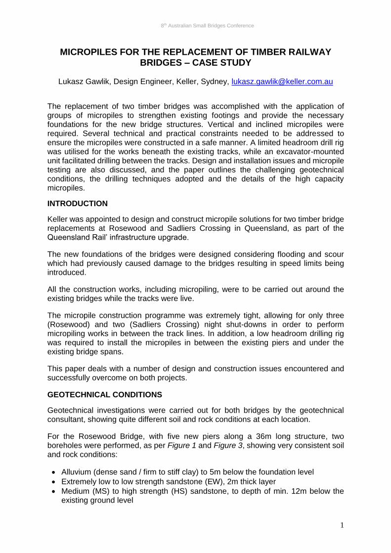
For the Rosewood Bridge, with five new piers along a 36m long structure, two boreholes were performed, as per Figure 1 and Figure 3, showing very consistent soil and rock conditions:
• Alluvium (dense sand / firm to stiff clay) to 5m below the foundation level
• Extremely low to low strength sandstone (EW), 2m thick layer
• Medium (MS) to high strength (HS) sandstone, to depth of min. 12m below the existing ground level
8th Australian Small Bridges Conference
2
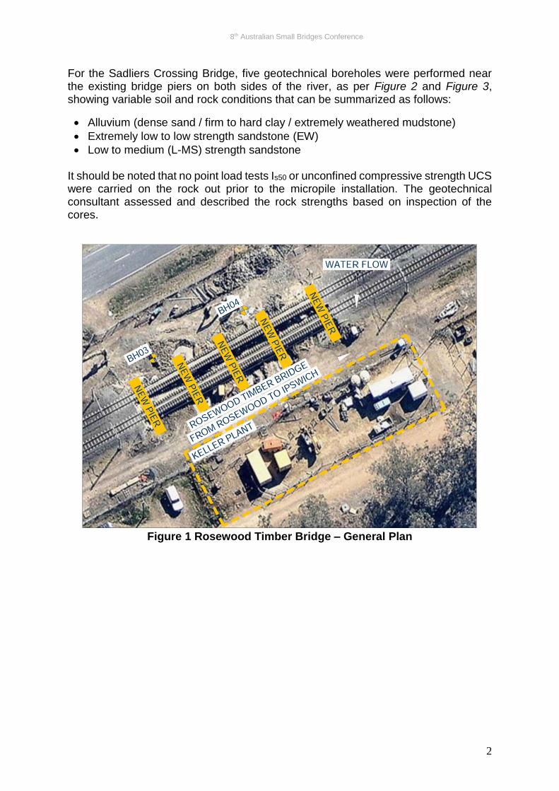
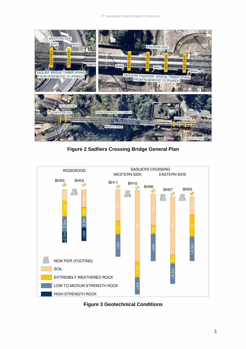
For the Sadliers Crossing Bridge, five geotechnical boreholes were performed near the existing bridge piers on both sides of the river, as per Figure 2 and Figure 3, showing variable soil and rock conditions that can be summarized as follows:
• Alluvium (dense sand / firm to hard clay / extremely weathered mudstone)
• Extremely low to low strength sandstone (EW)
• Low to medium (L-MS) strength sandstone It should be noted that no point load tests Is50 or unconfined compressive strength UCS were carried on the rock out prior to the micropile installation. The geotechnical consultant assessed and described the rock strengths based on inspection of the cores.
Figure 1 Rosewood Timber Bridge – General Plan
8th Australian Small Bridges Conference
3
Figure 2 Sadliers Crossing Bridge General Plan
Figure 3 Geotechnical Conditions
8th Australian Small Bridges Conference
4
DESIGN APPROACH
The geotechnical consultant, appointed by Queensland Rail, suggested self-drilling micropiles situated at the ends and in the middle of new reinforced concrete piers.
In order to fit the very tight construction time allowed by Queensland Rail, Keller proposed revised micropile solutions comprising an optimized number of high capacity micropiles under new piers. That reduction in number of micropiles was aimed at giving buffer time for the works that were to be carried out during the shut-downs.
Apart from dead and live loads typical for this type of structure, Keller was required to account for large lateral loads due to flooding (Rosewood and Sadliers Crossing) and scour around the micropiles (Rosewood). The geotechnical consultant assessed that the alluvium soil may be washed out up to 2m below the existing ground level, despite the new concrete protection, exposing the footings and increasing likelihood of bridge collapse.
The number of micropiles and their configuration under each foundation, as proposed by Keller, resulted in large compression and tension, which were quite a challenge in terms of structural capacity and, as will be further explained, geotechnical capacity.
Keller was also responsible for design and construction of the micropile connections in the new reinforced concrete piers, using bearing plates and tie-bars welded to the casing.
MICROPILE CONFIGURATION
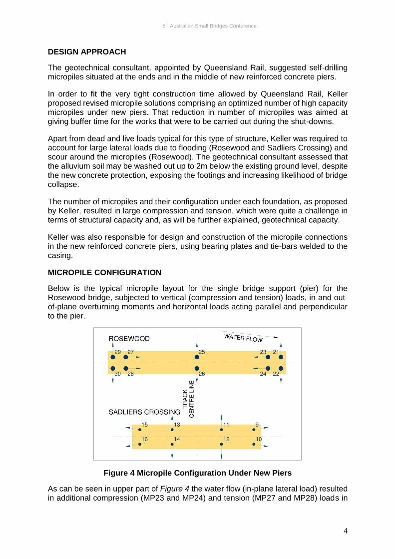
Below is the typical micropile layout for the single bridge support (pier) for the Rosewood bridge, subjected to vertical (compression and tension) loads, in and out-of-plane overturning moments and horizontal loads acting parallel and perpendicular to the pier.
Figure 4 Micropile Configuration Under New Piers
As can be seen in upper part of Figure 4 the water flow (in-plane lateral load) resulted in additional compression (MP23 and MP24) and tension (MP27 and MP28) loads in
8th Australian Small Bridges Conference
5
the micropiles inclined, towards and away from the water flow respectively. The out-of-plane lateral loads generated by acceleration or braking of train vehicles were to be carried by micropiles inclined along the track centre line (MP29, MP28, MP25, MP26, MP21 and MP22). These micropiles, installed at an angle of 15 to 20 deg to the vertical, were to provide the new Rosewood Bridge with three-dimensional stability.
The lower part of Figure 4 shows a typical micropile layout for the Sadliers Crossing Bridge, where no water flow was to be considered in the design. The 15 deg inclination to the vertical and 10 deg horizontal rotation of the micropiles in the corners was associated with three-dimensional stability, as well as lateral loads from train braking/acceleration and wind loads.
The micropile loads were sensitive to the micropile inclination and rotation, requiring comprehensive analysis of a number of load cases and micropile configurations, considering the allowable micropile tolerance on position and inclination, in accordance with the piling code and the project specification.
DRILLING SYSTEM
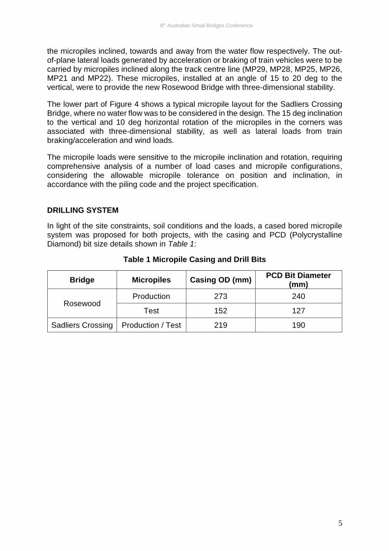
In light of the site constraints, soil conditions and the loads, a cased bored micropile system was proposed for both projects, with the casing and PCD (Polycrystalline Diamond) bit size details shown in Table 1:
Table 1 Micropile Casing and Drill Bits
Bridge Micropiles Casing OD (mm) PCD Bit Diameter
(mm)
Rosewood Production 273 240
Test 152 127
Sadliers Crossing Production / Test 219 190
8th Australian Small Bridges Conference
6
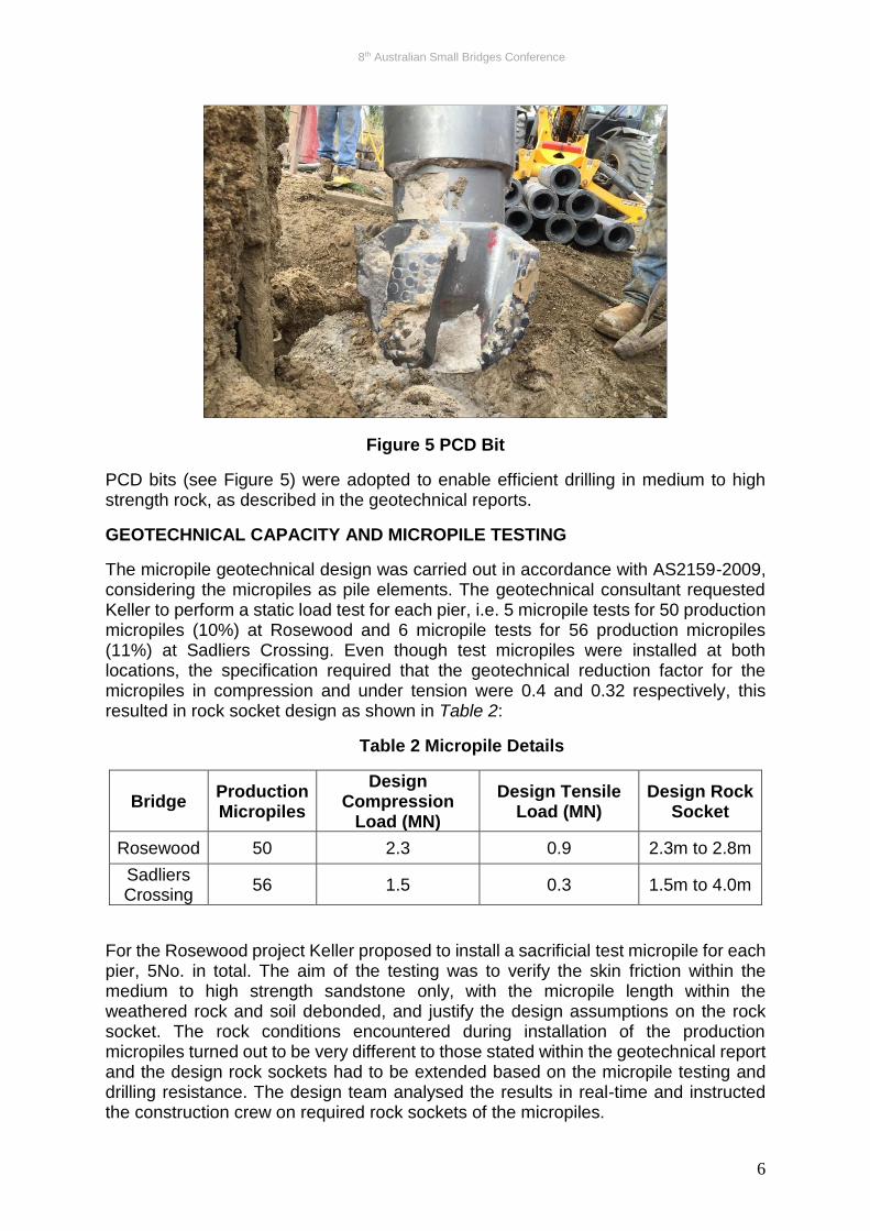
Figure 5 PCD Bit
PCD bits (see Figure 5) were adopted to enable efficient drilling in medium to high strength rock, as described in the geotechnical reports.
GEOTECHNICAL CAPACITY AND MICROPILE TESTING
The micropile geotechnical design was carried out in accordance with AS2159-2009, considering the micropiles as pile elements. The geotechnical consultant requested Keller to perform a static load test for each pier, i.e. 5 micropile tests for 50 production micropiles (10%) at Rosewood and 6 micropile tests for 56 production micropiles (11%) at Sadliers Crossing. Even though test micropiles were installed at both locations, the specification required that the geotechnical reduction factor for the micropiles in compression and under tension were 0.4 and 0.32 respectively, this resulted in rock socket design as shown in Table 2:
Table 2 Micropile Details
Bridge Production Micropiles
Design Compression
Load (MN)
Design Tensile Load (MN)
Design Rock Socket
Rosewood 50 2.3 0.9 2.3m to 2.8m
Sadliers Crossing
56 1.5 0.3 1.5m to 4.0m
For the Rosewood project Keller proposed to install a sacrificial test micropile for each pier, 5No. in total. The aim of the testing was to verify the skin friction within the medium to high strength sandstone only, with the micropile length within the weathered rock and soil debonded, and justify the design assumptions on the rock socket. The rock conditions encountered during installation of the production micropiles turned out to be very different to those stated within the geotechnical report and the design rock sockets had to be extended based on the micropile testing and drilling resistance. The design team analysed the results in real-time and instructed the construction crew on required rock sockets of the micropiles.
8th Australian Small Bridges Conference
7
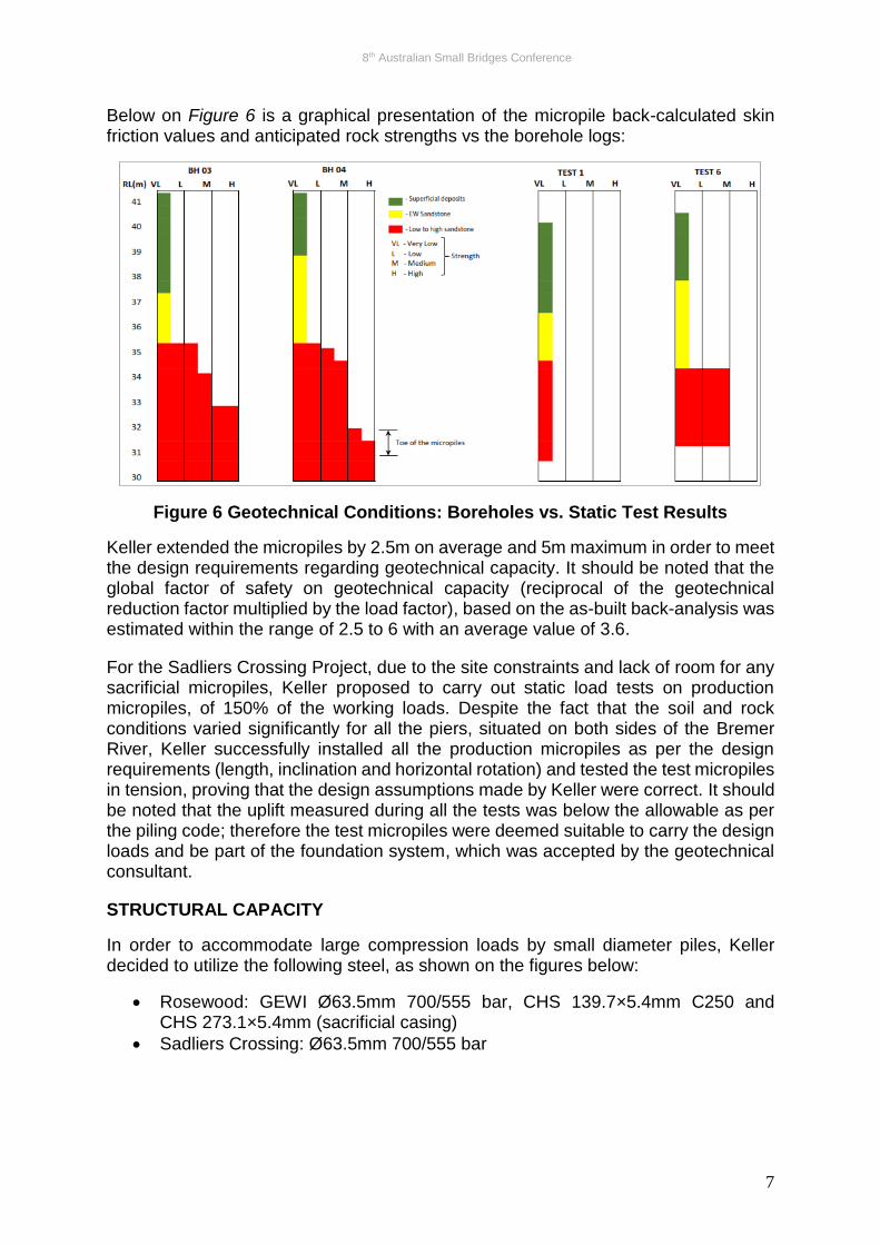
Below on Figure 6 is a graphical presentation of the micropile back-calculated skin friction values and anticipated rock strengths vs the borehole logs:
Figure 6 Geotechnical Conditions: Boreholes vs. Static Test Results
Keller extended the micropiles by 2.5m on average and 5m maximum in order to meet the design requirements regarding geotechnical capacity. It should be noted that the global factor of safety on geotechnical capacity (reciprocal of the geotechnical reduction factor multiplied by the load factor), based on the as-built back-analysis was estimated within the range of 2.5 to 6 with an average value of 3.6.
For the Sadliers Crossing Project, due to the site constraints and lack of room for any sacrificial micropiles, Keller proposed to carry out static load tests on production micropiles, of 150% of the working loads. Despite the fact that the soil and rock conditions varied significantly for all the piers, situated on both sides of the Bremer River, Keller successfully installed all the production micropiles as per the design requirements (length, inclination and horizontal rotation) and tested the test micropiles in tension, proving that the design assumptions made by Keller were correct. It should be noted that the uplift measured during all the tests was below the allowable as per the piling code; therefore the test micropiles were deemed suitable to carry the design loads and be part of the foundation system, which was accepted by the geotechnical consultant.
STRUCTURAL CAPACITY
In order to accommodate large compression loads by small diameter piles, Keller decided to utilize the following steel, as shown on the figures below:
• Rosewood: GEWI Ø63.5mm 700/555 bar, CHS 139.7×5.4mm C250 and CHS 273.1×5.4mm (sacrificial casing)
• Sadliers Crossing: Ø63.5mm 700/555 bar
8th Australian Small Bridges Conference
8
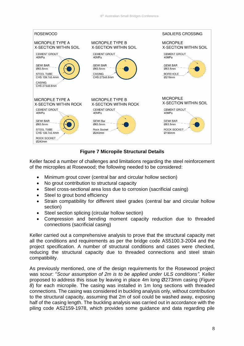
Figure 7 Micropile Structural Details
Keller faced a number of challenges and limitations regarding the steel reinforcement of the micropiles at Rosewood; the following needed to be considered:
• Minimum grout cover (central bar and circular hollow section)
• No grout contribution to structural capacity
• Steel cross-sectional area loss due to corrosion (sacrificial casing)
• Steel to grout bond efficiency
• Strain compatibility for different steel grades (central bar and circular hollow section)
• Steel section splicing (circular hollow section)
• Compression and bending moment capacity reduction due to threaded connections (sacrificial casing)
Keller carried out a comprehensive analysis to prove that the structural capacity met all the conditions and requirements as per the bridge code AS5100.3-2004 and the project specification. A number of structural conditions and cases were checked, reducing the structural capacity due to threaded connections and steel strain compatibility.
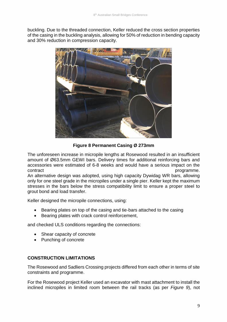
As previously mentioned, one of the design requirements for the Rosewood project was scour: “Scour assumption of 2m is to be applied under ULS conditions”. Keller proposed to address this issue by leaving in place 4m long Ø273mm casing (Figure 8) for each micropile. The casing was installed in 1m long sections with threaded connections. The casing was considered in buckling analysis only, without contribution to the structural capacity, assuming that 2m of soil could be washed away, exposing half of the casing length. The buckling analysis was carried out in accordance with the piling code AS2159-1978, which provides some guidance and data regarding pile
8th Australian Small Bridges Conference
9
buckling. Due to the threaded connection, Keller reduced the cross section properties of the casing in the buckling analysis, allowing for 50% of reduction in bending capacity and 30% reduction in compression capacity.
Figure 8 Permanent Casing Ø 273mm
The unforeseen increase in micropile lengths at Rosewood resulted in an insufficient amount of Ø63.5mm GEWI bars. Delivery times for additional reinforcing bars and accessories were estimated of 6-8 weeks and would have a serious impact on the contract programme. An alternative design was adopted, using high capacity Dywidag WR bars, allowing only for one steel grade in the micropiles under a single pier. Keller kept the maximum stresses in the bars below the stress compatibility limit to ensure a proper steel to grout bond and load transfer.
Keller designed the micropile connections, using:
• Bearing plates on top of the casing and tie-bars attached to the casing
• Bearing plates with crack control reinforcement,
and checked ULS conditions regarding the connections:
• Shear capacity of concrete
• Punching of concrete
CONSTRUCTION LIMITATIONS
The Rosewood and Sadliers Crossing projects differed from each other in terms of site constraints and programme.
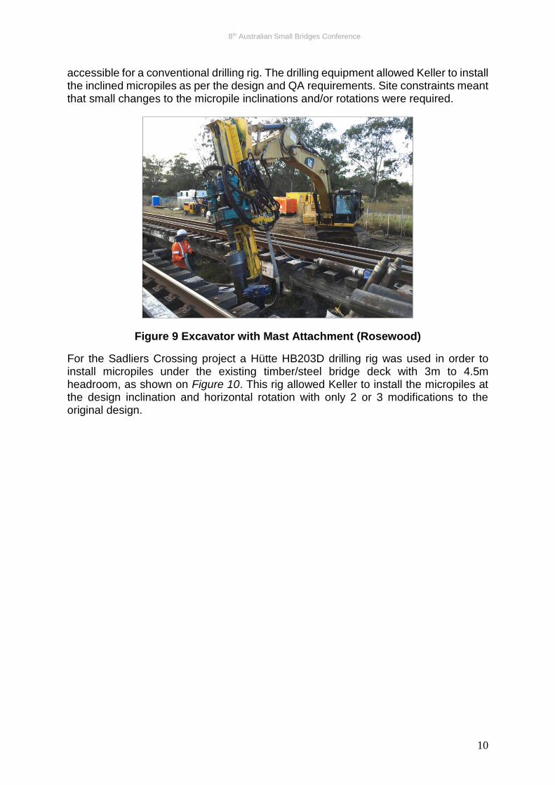
For the Rosewood project Keller used an excavator with mast attachment to install the inclined micropiles in limited room between the rail tracks (as per Figure 9), not
8th Australian Small Bridges Conference
10
accessible for a conventional drilling rig. The drilling equipment allowed Keller to install the inclined micropiles as per the design and QA requirements. Site constraints meant that small changes to the micropile inclinations and/or rotations were required.
Figure 9 Excavator with Mast Attachment (Rosewood)
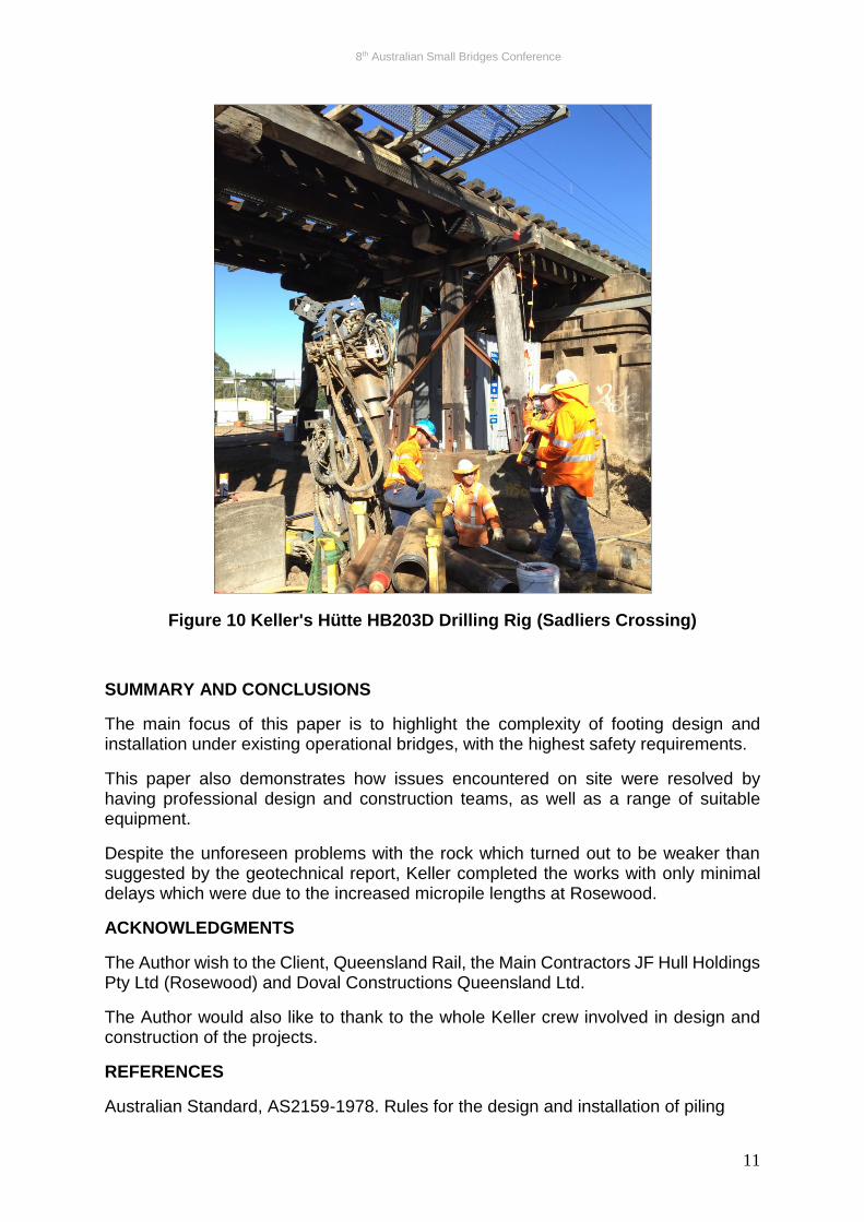
For the Sadliers Crossing project a Hütte HB203D drilling rig was used in order to install micropiles under the existing timber/steel bridge deck with 3m to 4.5m headroom, as shown on Figure 10. This rig allowed Keller to install the micropiles at the design inclination and horizontal rotation with only 2 or 3 modifications to the original design.
8th Australian Small Bridges Conference
11
Figure 10 Keller's Hütte HB203D Drilling Rig (Sadliers Crossing)
SUMMARY AND CONCLUSIONS
The main focus of this paper is to highlight the complexity of footing design and installation under existing operational bridges, with the highest safety requirements.
This paper also demonstrates how issues encountered on site were resolved by having professional design and construction teams, as well as a range of suitable equipment.
Despite the unforeseen problems with the rock which turned out to be weaker than suggested by the geotechnical report, Keller completed the works with only minimal delays which were due to the increased micropile lengths at Rosewood.
ACKNOWLEDGMENTS
The Author wish to the Client, Queensland Rail, the Main Contractors JF Hull Holdings Pty Ltd (Rosewood) and Doval Constructions Queensland Ltd.
The Author would also like to thank to the whole Keller crew involved in design and construction of the projects.
REFERENCES
Australian Standard, AS2159-1978. Rules for the design and installation of piling
8th Australian Small Bridges Conference
12
Australian Standard, AS2159-2009. Design and installation
Australian Standard, AS3600-2009. Concrete Structures
Australian Standard, AS4100-1998. Steel Structures
Australian Standard, AS5100.3-2004. Bridge design. Part 3: Foundations and soil-supporting structures
P.J.N. Pells, December 2002, Soil / Rock layers of the assumed generalised rock; rock classification as per Geotechnical Parameters of Sydney Sandstone and Shale
AUTHOR BIOGRAPHY
Lukasz Gawlik has almost ten years’ experience in geotechnical engineering and ground improvement. He has undertaken design and construction for ground anchors, micropiles, Jet Grouting and rigid inclusions, amongst others. Lukasz is proficient in geotechnical software and advanced numerical analysis, and brings experience from his seven years in Poland to the projects he has worked on around Australia.