integrated gasification combined cycle - … gasification combined-cycle (igcc) systems combine a...
TRANSCRIPT
PDHonline Course E303 (4 PDH)
Integrated Gasification Combined Cycle
2012
Instructor: Lee Layton, PE
PDH Online | PDH Center5272 Meadow Estates Drive
Fairfax, VA 22030-6658Phone & Fax: 703-988-0088
www.PDHonline.orgwww.PDHcenter.com
An Approved Continuing Education Provider
www.PDHcenter.com PDH Course E303 www.PDHonline.org
Integrated Gasification Combined Cycle Power Plants
Lee Layton, P.E
Table of Contents Section Page Introduction ……………………………………………. 3 I. Fuel Source ………………………………………….. 5 II. Gasification ………………………………………… 14 III. Combined Cycle Power Plant …………………….. 21 IV. Integrated Gasification Combined Cycle Plant ….. 32 Summary …………………………………………..… 40
© Lee Layton. Page 2 of 40
Photo Credit: The figure on the cover is courtesy of the National Energy Technology Laboratory.
www.PDHcenter.com PDH Course E303 www.PDHonline.org
Introduction
Integrated gasification combined-cycle (IGCC) systems combine a coal gasification unit with a gas fired combined cycle power generation unit. The first stage is a coal gasification process. The second stage takes the cleaned gas and burns it in a conventional combustion turbine to produce electrical energy, and the hot exhaust gas is recovered and used to boil water, creating steam for a steam turbine which also produces electrical energy. In typical plants, about 65% of the electrical energy is produced by the combustion turbine and 35% by the steam turbine.
An integrated gasification combined cycle (IGCC) is a power plant that uses synthetic gas as its fuel source. The synthetic gas, also known as syngas, is used to power a combustion turbine generator whose waste heat is then used to power a steam turbine. The gasification process can use coal, heavy petroleum residues, or biomass as the feedstock. An integrated coal gasification combined cycle power plant is the most environmentally friendly coal-fired power generation plant available today. The plants can generate electric power with very little greenhouse gas emissions.
Coal gasification is the process of converting coal to a gaseous fuel through partial oxidation. The coal is fed into a high-temperature pressurized container along with steam and a limited amount of oxygen to produce a gas. The gas is consists mainly of carbon monoxide and hydrogen. The gas is cooled and undesirable components, such as carbon dioxide and sulphur are removed.
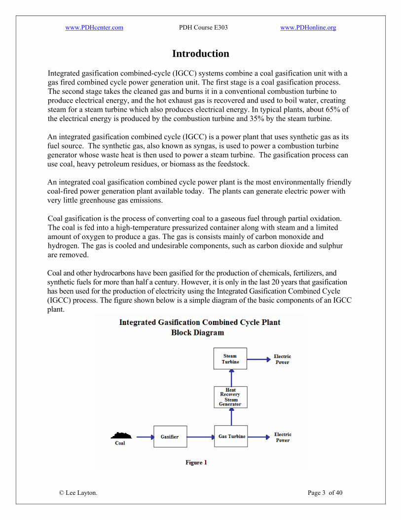
Coal and other hydrocarbons have been gasified for the production of chemicals, fertilizers, and synthetic fuels for more than half a century. However, it is only in the last 20 years that gasification has been used for the production of electricity using the Integrated Gasification Combined Cycle (IGCC) process. The figure shown below is a simple diagram of the basic components of an IGCC plant.
© Lee Layton. Page 3 of 40
www.PDHcenter.com PDH Course E303 www.PDHonline.org
Looking at Figure 1 we see that an IGCC plant consists of a gasification plant, a gas-fired turbine, and heat recovery steam generator and a steam turbine. A hydrocarbon feedstock, such as coal, is gasified in a high-pressure, high-temperature gasifier with either air or oxygen produced in an air separation unit (ASU). The resulting synthesized gas (syngas) is cooled, cleaned, and fired in a combustion turbine. The hot exhaust from the combustion turbine passes through a heat recovery steam generator (HRSG) where it produces steam that drives a steam turbine. Electric power is produced from both the gas and steam turbine-generators. By removing the emission-forming constituents from the syngas under pressure before combustion in the power block, an IGCC power plant produces very low levels of air pollutants (NOx, SO2, and PM) and volatile mercury. IGCC uses a combined cycle format with a combustion turbine driven by the combusted syngas, while the exhaust gases are heat exchanged with water/steam to generate superheated steam to drive a steam turbine. Using IGCC, more of the power comes from the combustion turbine. Typically 60-70% of the power comes from the combustion turbine with IGCC, compared with about 20% using pressurized fluidized bed combustion (PFBC.)
In general the advantages of IGCC are:
• Theoretically an IGCC can achieve up to 50% thermal efficiency (In practice, the initial plants have fallen far short of this level.)
• It produces about half the volume of solid wastes as a conventional coal power plant. • It uses 20-50% less water compared to a conventional coal power station. • It can utilize a variety of fuels, like heavy oils, petroleum cokes, and coals. • Carbon capture is easier and costs less than capture from a pulverized coal plant. • A minimum of 95% of the sulphur is removed. • Nitrogen oxides (NOx) emissions are less than most types of existing coal-fired
generating units.
IGCC will compete directly against other clean coal technologies such as the supercritical pulverized coal (SCPC) design. Presently, IGCC plants cost 20 to 25 percent more than a comparable SCPC power plant at any given site.
© Lee Layton. Page 4 of 40
In the first section of this course we will look at the primary feedstock for IGCC power plants – coal. Subsequent sections will go into more detail about the gasification process and combined cycle power plants.
www.PDHcenter.com PDH Course E303 www.PDHonline.org
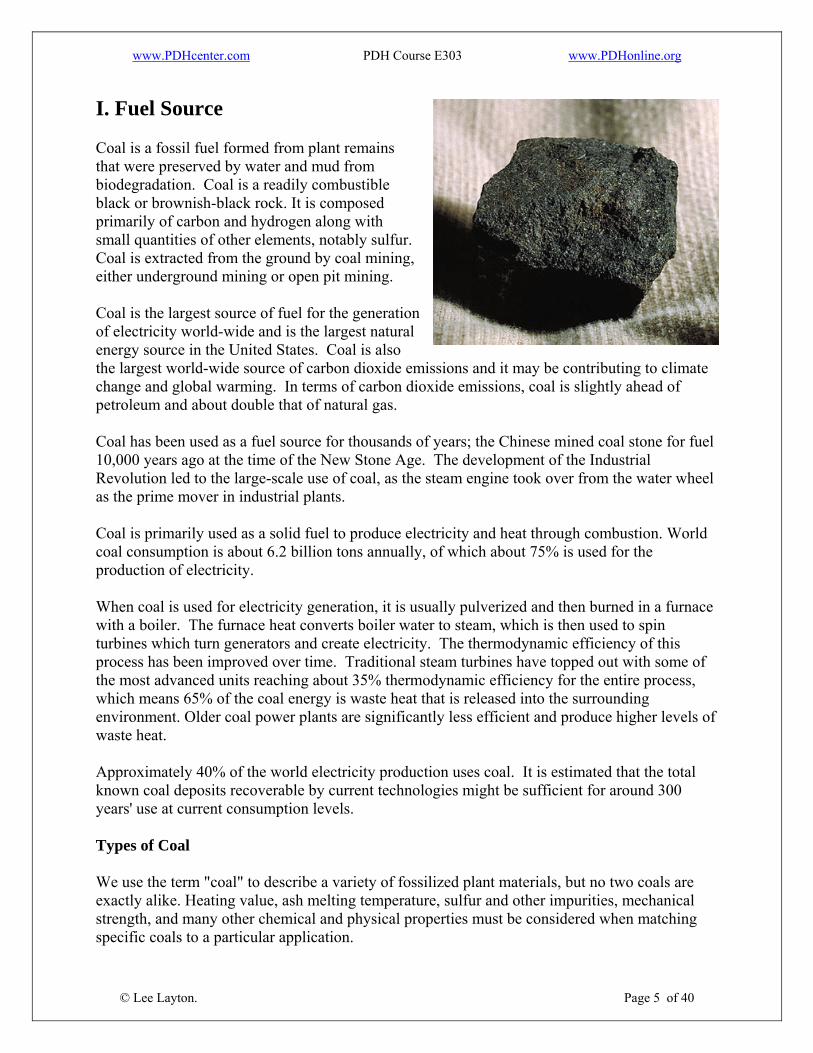
I. Fuel Source Coal is a fossil fuel formed from plant remains that were preserved by water and mud from biodegradation. Coal is a readily combustible black or brownish-black rock. It is composed primarily of carbon and hydrogen along with small quantities of other elements, notably sulfur. Coal is extracted from the ground by coal mining, either underground mining or open pit mining. Coal is the largest source of fuel for the generation of electricity world-wide and is the largest natural energy source in the United States. Coal is also the largest world-wide source of carbon dioxide emissions and it may be contributing to climate change and global warming. In terms of carbon dioxide emissions, coal is slightly ahead of petroleum and about double that of natural gas. Coal has been used as a fuel source for thousands of years; the Chinese mined coal stone for fuel 10,000 years ago at the time of the New Stone Age. The development of the Industrial Revolution led to the large-scale use of coal, as the steam engine took over from the water wheel as the prime mover in industrial plants. Coal is primarily used as a solid fuel to produce electricity and heat through combustion. World coal consumption is about 6.2 billion tons annually, of which about 75% is used for the production of electricity. When coal is used for electricity generation, it is usually pulverized and then burned in a furnace with a boiler. The furnace heat converts boiler water to steam, which is then used to spin turbines which turn generators and create electricity. The thermodynamic efficiency of this process has been improved over time. Traditional steam turbines have topped out with some of the most advanced units reaching about 35% thermodynamic efficiency for the entire process, which means 65% of the coal energy is waste heat that is released into the surrounding environment. Older coal power plants are significantly less efficient and produce higher levels of waste heat. Approximately 40% of the world electricity production uses coal. It is estimated that the total known coal deposits recoverable by current technologies might be sufficient for around 300 years' use at current consumption levels. Types of Coal We use the term "coal" to describe a variety of fossilized plant materials, but no two coals are exactly alike. Heating value, ash melting temperature, sulfur and other impurities, mechanical strength, and many other chemical and physical properties must be considered when matching specific coals to a particular application.
© Lee Layton. Page 5 of 40

www.PDHcenter.com PDH Course E303 www.PDHonline.org
Coal is classified into four general categories, or "ranks." They range from lignite through sub-bituminous and bituminous to anthracite, reflecting the progressive response of individual deposits of coal to increasing heat and pressure. The carbon content of coal supplies most of its heating value, but other factors also influence the amount of energy it contains per unit of weight. (The amount of energy in coal is expressed in British thermal units per pound. A BTU is the amount of heat required to raise the temperature of one pound of water one degree Fahrenheit.) About 90 percent of the coal in the U.S. falls in the bituminous and sub-bituminous categories, which rank below anthracite and, for the most part, contain less energy per unit of weight. Bituminous coal predominates in the Eastern and Mid-continent coal fields, while sub-bituminous coal is generally found in the Western states and Alaska. Lignite ranks the lowest and is the youngest of the coals. Most lignite is mined in Texas, but large deposits also are found in Montana, North Dakota, and some Gulf Coast states. Anthracite Anthracite is coal with the highest carbon content, between 86 and 98 percent, and a heat value of nearly 15,000 BTUs-per-pound. Most frequently associated with home heating, anthracite is a very small segment of the U.S. coal market. There are 7.3 billion tons of anthracite reserves in the United States, found mostly in 11 northeastern counties in Pennsylvania. Bituminous The most plentiful form of coal in the United States, bituminous coal is used primarily to generate electricity and make coke for the steel industry. The fastest growing market for coal is supplying heat for industrial processes. Bituminous coal has a carbon content ranging from 45 to 86 percent carbon and a heat value of 10,500 to 15,500 BTUs-per-pound. The carbon content of bituminous coal is around 60-80%; the rest is composed of water, air, hydrogen, and sulfur. Bituminous coal is a relatively soft coal containing a tarlike substance called bitumen. It is of higher quality than lignite coal but poorer quality than anthracite coal. Bituminous coal is usually black, sometimes dark brown, often with well-defined bands of bright and dull material. Bituminous coal seams are identified by the distinctive sequence of bright and dark bands and are classified accordingly as either "dull, bright-banded" or "bright, dull-banded" and so on. Bituminous coals are graded according to reflectance, moisture content, volatile content, plasticity and ash content. Generally, the highest value bituminous coals are those which have a specific grade of plasticity, volatility and low ash content, especially with low carbonate, phosphorus and sulfur. Plasticity is vital for coking as it represents its ability to gradually form specific plasticity phases during the coking process. Low phosphorus content is vital for these coals, as phosphorus is detrimental to steel making.
© Lee Layton. Page 6 of 40
www.PDHcenter.com PDH Course E303 www.PDHonline.org
Coking coal is best if it has a very narrow range of volatility and plasticity. Volatile content and swelling index are used to select coals for coke blending as well. Volatility is also critical for steel-making and power generation, as this determines the burn rate of the coal. High volatile content coals, while easy to ignite often are not as prized as moderately volatile coals; low volatile coal may be difficult to ignite although it will contain more energy per unit volume. The smelter must balance the volatile content of the coals to optimize the ease of ignition, burn rate, and energy output of the coal. Low ash, sulfur, and carbonate coals are good choices for power generation because they do not produce much boiler slag and they do not require as much effort to scrub the flue gases to remove particulate matter. Carbonates are detrimental to the boiler apparatus because they stick to the equipment. Sulfide contents are also detrimental to some degree as this sulfur is emitted and can form smog, acid rain and haze pollution. Scrubbers on the flue gases are used to eliminate particulate and sulfur emissions. When used for industrial processes, bituminous coal must first be "coked" to remove volatile components. Coking is achieved by heating the coal in the absence of oxygen, which drives off volatile hydrocarbons such as propane, benzene and other aromatic hydrocarbons, and some sulfur gases. This also drives off the amount of the contained water of the bituminous coal. Coking coal is used in the manufacture of steel, where carbon must be as volatile-free and ash-free as possible. Bituminous coal is mined in the Appalachian region, primarily for power generation. Mining is done via both surface and underground mines. Sub-bituminous Ranking below bituminous is sub-bituminous coal with 35-45 percent carbon content and a heat value between 8,300 and 13,000 BTUs-per-pound. Reserves are located mainly in a half-dozen Western states and Alaska. Although its heat value is lower, this coal generally has a lower sulfur content than other types, which makes it attractive for use because it is cleaner burning. Sub-bituminous coal is a type of coal whose properties range from those of lignite to those of bituminous coal and is used primarily as fuel for steam-electric power generation. Sub-bituminous coal may be dull, dark brown to black, soft and crumbly at the lower end of the range, to bright, jet-black, hard, and relatively strong at the upper end. It contains 20-30% inherent moisture by weight. A major source of sub-bituminous coal in the United States is the Powder River Basin in Wyoming. Its relatively low density and high water content renders some types of sub-bituminous coal susceptible to spontaneous combustion if not packed densely during storage in order to exclude free air flow.
© Lee Layton. Page 7 of 40
www.PDHcenter.com PDH Course E303 www.PDHonline.org
Lignite Lignite is a geologically young coal which has the lowest carbon content, 25-35 percent, and a heat value ranging between 4,000 and 8,300 BTUs-per-pound. Sometimes called brown coal, it is mainly used for electric power generation. It is the lowest rank of coal and used almost exclusively as fuel for steam-electric power generation. It is brownish-black and has a high inherent moisture content, sometimes as high as 66%, and very high ash (50%) content compared with bituminous coal. It is also a heterogeneous mixture of compounds for which no single structural formula will suffice. Because of its low energy density, brown coal is inefficient to transport and is not traded extensively on the world market compared with higher coal grades. It is often burned in power stations constructed very close to any mines. Carbon dioxide emissions from brown coal fired plants are generally much higher than for comparable black coal plants. Lignite can be separated into two types. The first is fossil wood and the second form is the compact lignite or perfect lignite. Fossil wood is barely classified as coal and is a very marginal coal feedstock with a heat rate of less than 6,300 BTU’s. While still an inefficient coal, compact lignite has a heat rate of greater than 6,300 BTU’s. Energy density The energy density of coal can be expressed in kilowatt-hours per pound (kWh/lb) of coal. The energy density of coal is about 3 kWh/lb of coal. When you consider that the thermal efficiency of a coal-fired power plant is about 30% then the only about 0.91 kWh’s are produced for each pound of coal burned. The remainder is given up as waste heat and other losses in the generation process. Said another way, it takes about 1.1 pounds of coal to generate one kWh. Each kilowatt-hour produced also generates about 2 pounds of CO2. To put this in laymen’s terms, consider the energy required to light a 100-watt incandescent light bulb for one year assuming 4-hours use per day. It will require 146 kWh’s per year (100 * 4 * 365 / 1,000 = 146) to light the lamp for four hours per day for one year. Since it takes 1.1 pounds of coal per kWh, 160 pounds of coal will be required and almost 300 pounds of CO2 will be generated. In comparison, an equivalent compact fluorescent lamp is only 23 watts and will only use 34 kWh’s per year, 37 pounds of coal, and about 70 pounds of CO2. Another interesting comparison is the CO2 generated from coal versus other sources. As we mentioned, coal-fired generation results in about 2 lbs/kWh of CO2. For oil-fired generation it is slightly less than 2 lbs/kWh and for natural gas, the CO2 emissions are about 1.3 lbs/kWh. For nuclear power, the CO2 are miniscule, perhaps 0.1 lbs/kWh. World coal reserves
© Lee Layton. Page 8 of 40
The recoverable coal reserves are estimated to be around 900 billion tons. This is equal to about 4,417 billion barrels of oil equivalent (BBOE). The annual coal consumption is about 46 million barrels of oil or 17 BBOE. If consumption continues at this rate the reserves will last 260 years.

www.PDHcenter.com PDH Course E303 www.PDHonline.org
As a comparison, natural gas provides 51 million BOE and oil provides 76 million barrels per day. United States Coal Reserves Of the three fossil fuels, coal has the most widely distributed reserves; coal is mined in over 100 countries, and on all continents except Antarctica. The largest reserves are found in the United States, Russia, Australia, China, India and South Africa. In the continental United States, the coal largest reserves are divided into eleven geographic regions. They are,
1. Northern Appalachian 2. Central Appalachian 3. Southern Appalachian 4. Gulf 5. Illinois Basin 6. Western Interior 7. Plains (also called North Dakota Lignite) 8. Powder River Basin 9. Rockies 10. Southwest 11. Northwest
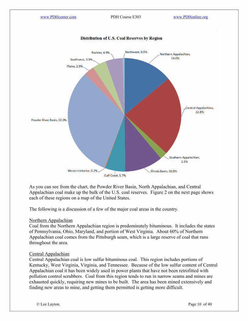
The following chart shows the supply and percent of the U.S. coal reserves by region.
© Lee Layton. Page 9 of 40
www.PDHcenter.com PDH Course E303 www.PDHonline.org
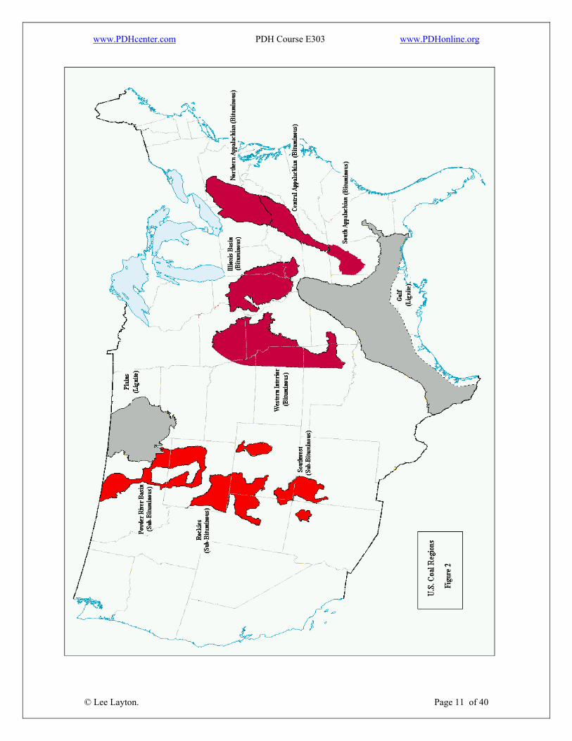
As you can see from the chart, the Powder River Basin, North Appalachian, and Central Appalachian coal make up the bulk of the U.S. coal reserves. Figure 2 on the next page shows each of these regions on a map of the United States. The following is a discussion of a few of the major coal areas in the country. Northern Appalachian Coal from the Northern Appalachian region is predominately bituminous. It includes the states of Pennsylvania, Ohio, Maryland, and portion of West Virginia. About 60% of Northern Appalachian coal comes from the Pittsburgh seam, which is a large reserve of coal that runs throughout the area. Central Appalachian
© Lee Layton. Page 10 of 40
Central Appalachian coal is low sulfur bituminous coal. This region includes portions of Kentucky, West Virginia, Virginia, and Tennessee. Because of the low sulfur content of Central Appalachian coal it has been widely used in power plants that have not been retrofitted with pollution control scrubbers. Coal from this region tends to run in narrow seams and mines are exhausted quickly, requiring new mines to be built. The area has been mined extensively and finding new areas to mine, and getting them permitted is getting more difficult.
www.PDHcenter.com PDH Course E303 www.PDHonline.org
© Lee Layton. Page 11 of 40
www.PDHcenter.com PDH Course E303 www.PDHonline.org
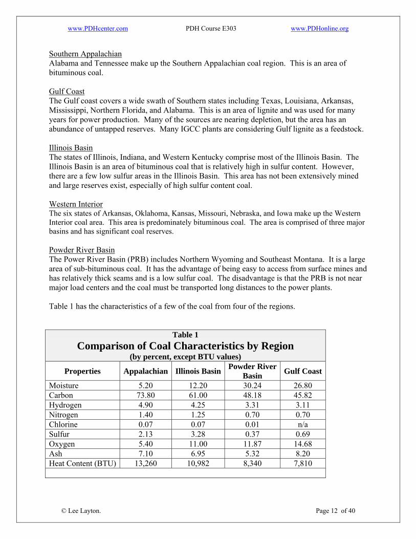
Southern Appalachian Alabama and Tennessee make up the Southern Appalachian coal region. This is an area of bituminous coal. Gulf Coast The Gulf coast covers a wide swath of Southern states including Texas, Louisiana, Arkansas, Mississippi, Northern Florida, and Alabama. This is an area of lignite and was used for many years for power production. Many of the sources are nearing depletion, but the area has an abundance of untapped reserves. Many IGCC plants are considering Gulf lignite as a feedstock. Illinois Basin The states of Illinois, Indiana, and Western Kentucky comprise most of the Illinois Basin. The Illinois Basin is an area of bituminous coal that is relatively high in sulfur content. However, there are a few low sulfur areas in the Illinois Basin. This area has not been extensively mined and large reserves exist, especially of high sulfur content coal. Western Interior The six states of Arkansas, Oklahoma, Kansas, Missouri, Nebraska, and Iowa make up the Western Interior coal area. This area is predominately bituminous coal. The area is comprised of three major basins and has significant coal reserves. Powder River Basin The Power River Basin (PRB) includes Northern Wyoming and Southeast Montana. It is a large area of sub-bituminous coal. It has the advantage of being easy to access from surface mines and has relatively thick seams and is a low sulfur coal. The disadvantage is that the PRB is not near major load centers and the coal must be transported long distances to the power plants. Table 1 has the characteristics of a few of the coal from four of the regions.
Table 1 Comparison of Coal Characteristics by Region
(by percent, except BTU values)
Properties Appalachian Illinois Basin Powder River Basin Gulf Coast
Moisture 5.20 12.20 30.24 26.80 Carbon 73.80 61.00 48.18 45.82 Hydrogen 4.90 4.25 3.31 3.11 Nitrogen 1.40 1.25 0.70 0.70 Chlorine 0.07 0.07 0.01 n/a Sulfur 2.13 3.28 0.37 0.69 Oxygen 5.40 11.00 11.87 14.68 Ash 7.10 6.95 5.32 8.20 Heat Content (BTU) 13,260 10,982 8,340 7,810
© Lee Layton. Page 12 of 40
www.PDHcenter.com PDH Course E303 www.PDHonline.org
From Table 1 we see that the Appalachian coal has the highest BTU value with a sulfur content of slightly over 2%. In comparison, the Powder River Basin coal has a much lower BTU content (8,340), but has a sulfur content of only 0.37% while the Illinois Basin coal has a moderately good BTU content of 10,982 and very high sulfur content at over 3%. Environmental effects Unlike oil and natural gas, coal is plentiful and relatively inexpensive. The problem with coal – like one of the fundamental problems with petroleum – is that the combustion of coal creates a number of potentially adverse environmental effects of coal-fired power generation plants. These effects include:
• Release of carbon dioxide and methane, both of which are greenhouse gases • Waste products including uranium, thorium, and other heavy metals • Acid rain • Interference with groundwater and water table levels • Impact of water use on flows of rivers and consequential impact on other land uses
Integrated gasification combined cycle plants are one of the new “clean coal” technologies that produces less pollutants and the pollutants that are generated are easier to manage, which should continue to make coal a viable fuel source for the foreseeable future.
© Lee Layton. Page 13 of 40
www.PDHcenter.com PDH Course E303 www.PDHonline.org
II. Gasification As we have just seen there are concerns with conventional coal-fired power plants. But there is another hydrocarbon option, which is gasification. This alternative is a process by which coal or other low-value hydrocarbons are gasified in a large chemical reactor. The resulting synthesis gas is cleaned and then used to fire an electric power plant. What makes gasification a “breakthrough” technology is that it combines the economic advantages of coal with the environmental benefits of natural gas. Gasification is a process that converts carbonaceous materials, such as coal, petroleum, or biomass, into carbon monoxide and hydrogen by reacting the raw material at high temperatures with a controlled amount of oxygen. The resulting gas mixture is called synthesized gas or syngas. Gasification is a very efficient method for extracting energy from many different types of organic materials. The world’s hydrocarbon resources are both finite and unevenly distributed. For nations such as the United States – with dwindling reserves of petroleum and natural gas – the only pathway to a future where energy prices are affordable and relatively stable is to conserve energy, improve energy efficiency, and produce electric power, from abundant domestic resources such as coal. Gasification is important because the syngas produced by this process could replace natural gas as the “fuel of choice” in the generation of electricity. Although gasification was invented almost 200 years ago, the technology has undergone a complete transformation in the last 50 years. The gasification process was originally developed in the early-1800s to produce gas for lighting and cooking and was known as “town gas”. Electricity and natural gas later replaced town gas for these applications, but the gasification process has been utilized for the production of synthetic chemicals and fuels since the 1920s. During World War II German engineers used gasification to produce synthetic fuel due to shortages of gasoline. Limited gasification projects continued until the energy crisis of the 1970s when research ramped up for a multitude of projects including IGCC power plants. Syngas from gasification is thoroughly cleaned before it is used in an IGCC power plant. Thus emissions of air pollutants and hazardous pollutants such as volatile mercury from coal-based power projects can be minimized. Gasification-based power plants can be cost-effectively configured to enable carbon dioxide capture. Coal can be gasified in various ways by properly controlling the mix of coal, oxygen, and steam within the gasifier. There are also several options for controlling the flow of coal in the gasification section. Most gasification processes use oxygen as the oxidizing medium. Gasification relies on chemical processes at elevated temperatures (>700°C), which distinguishes it from biological processes such as anaerobic digestion that produce biogas.
© Lee Layton. Page 14 of 40
Modern gasification technologies generally operate as follows:
www.PDHcenter.com PDH Course E303 www.PDHonline.org
1. A hydrocarbon feedstock is fed into a high-pressure, high-temperature chemical reactor
(gasifier) containing steam and a limited amount of oxygen.
2. Under these “reducing” conditions, the chemical bonds in the feedstock are severed by the extreme heat and pressure and a syngas is formed. This syngas is primarily a mixture of hydrogen and carbon monoxide.
3. The syngas is then cleaned using commercially available systems that remove
particulates, sulfur, and trace metals such as mercury. Although syngas has a lower heating value than natural gas, it can still be used in highly-efficient combined cycle electric power plants or to make many products presently made from natural gas, including ammonia fertilizers, methanol-derived chemicals, and clean-burning synthetic fuels. Gasification Process The heart of gasification-based systems is the gasifier. A gasifier converts hydrocarbon feedstock into gaseous components by applying heat under pressure in the presence of steam. A gasifier differs from a combustor in that the amount of air or oxygen available inside the gasifier is carefully controlled so that only a relatively small portion of the fuel burns completely. This "partial oxidation" process provides the heat. Rather than burning, most of the carbon-containing feedstock is chemically broken apart by the gasifier's heat and pressure, setting into motion chemical reactions that produce "syngas." Syngas is primarily hydrogen, carbon monoxide and other gaseous constituents; the composition of which can vary depending upon the conditions in the gasifier and the type of feedstock. Below is an overview of the differences between combustion and gasification.
Combustion vs. Gasification
Combustion Gasification• SO2 and SO3 are scrubbed out of
stack gas. Lime is used to create gypsum
• Hydrogen Sulfide is easily removed from syngas and converted into solid sulphur or sulfuric acid
• NOX is controlled with low NOX burners and catalytic converters
• NH3 washes out of gas with water
• Creates a large volume of flyash and sludge
• Ash is converted into glassy slag
• Mercury can be removed by contracting flue gas with activated carbon
• 90% of mercury is removed by passing high pressure syngas through activated carbon bed
© Lee Layton. Page 15 of 40
Combustion is an exothermic reaction between a fuel and an oxidizer and, for a carbonaceous fuel, may be expressed:
www.PDHcenter.com PDH Course E303 www.PDHonline.org
Fuel + Oxygen → Heat + H2O + CO2
Gasification is an exothermic reaction between a carbon fuel and an oxidizer in a reactor where the oxygen supply is limited (generally from 20 to 70 percent of the oxygen for complete combustion.) The reaction may be expressed:
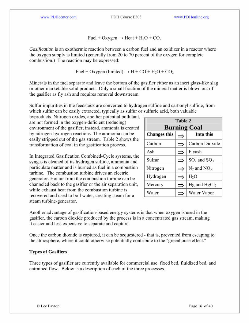
Fuel + Oxygen (limited) → H + CO + H2O + CO2 Minerals in the fuel separate and leave the bottom of the gasifier either as an inert glass-like slag or other marketable solid products. Only a small fraction of the mineral matter is blown out of the gasifier as fly ash and requires removal downstream. Sulfur impurities in the feedstock are converted to hydrogen sulfide and carbonyl sulfide, from which sulfur can be easily extracted, typically as sulfur or sulfuric acid, both valuable byproducts. Nitrogen oxides, another potential pollutant, are not formed in the oxygen-deficient (reducing) environment of the gasifier; instead, ammonia is created by nitrogen-hydrogen reactions. The ammonia can be easily stripped out of the gas stream. Table 2 shows the transformation of coal in the gasification process.
Table 2
In Integrated Gasification Combined-Cycle systems, the syngas is cleaned of its hydrogen sulfide, ammonia and particulate matter and is burned as fuel in a combustion turbine. The combustion turbine drives an electric generator. Hot air from the combustion turbine can be channeled back to the gasifier or the air separation unit, while exhaust heat from the combustion turbine is recovered and used to boil water, creating steam for a steam turbine-generator. Another advantage of gasification-based energy systems is that when oxygen is used in the gasifier, the carbon dioxide produced by the process is in a concentrated gas stream, making it easier and less expensive to separate and capture. Once the carbon dioxide is captured, it can be sequestered - that is, prevented from escaping to the atmosphere, where it could otherwise potentially contribute to the "greenhouse effect." Types of Gasifiers Three types of gasifier are currently available for commercial use: fixed bed, fluidized bed, and entrained flow. Below is a description of each of the three processes.
© Lee Layton. Page 16 of 40
Burning Coal Changes this ⇒ Into this
Carbon ⇒ Carbon Dioxide
Ash ⇒ Flyash
Sulfur ⇒ SO2 and SO3
Nitrogen ⇒ N2 and NOX
Hydrogen ⇒ H2O
Mercury ⇒ Hg and HgCl2
Water ⇒ Water Vapor
www.PDHcenter.com PDH Course E303 www.PDHonline.org
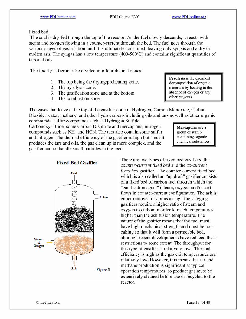
Fixed bed The coal is dry-fed through the top of the reactor. As the fuel slowly descends, it reacts with steam and oxygen flowing in a counter-current through the bed. The fuel goes through the various stages of gasification until it is ultimately consumed, leaving only syngas and a dry or molten ash. The syngas has a low temperature (400-500ºC) and contains significant quantities of tars and oils. The fixed gasifier may be divided into four distinct zones:
1. The top being the drying/preheating zone. 2. The pyrolysis zone. 3. The gasification zone and at the bottom. 4. The combustion zone.
The gases that leave at the top of the gasifier contain Hydrogen, Carbon Monoxide, Carbon Dioxide, water, methane, and other hydrocarbons including oils and tars as well as other organic compounds, sulfur compounds such as Hydrogen Sulfide, Carbonoxysulfide, some Carbon Disulfide and mercaptans, nitrogen compounds such as NH3 and HCN. The tars also contain some sulfur and nitrogen. The thermal efficiency of the gasifier is high but since it produces the tars and oils, the gas clean up is more complex, and the gasifier cannot handle small particles in the feed.
There are two types of fixed bed gasifiers: the counter-current fixed bed and the co-current fixed bed gasifier. The counter-current fixed which is also called an “up draft" gasifier consists of a fixed bed of carbon fuel through which the "gasification agent" (steam, oxygen and/or air) flows in counter-current configuration. The ash is either removed dry or as a slag. The slagging gasifiers require a higher ratio of steam and oxygen to carbon in order to reach temperatures higher than the ash fusion temperature. The nature of the gasifier means that the fuel must have high mechanical strength and must be non-caking so that it will form a permeable bed, although recent developments have reduced these restrictions to some extent. The throughput for this type of gasifier is relatively low. Thermal efficiency is high as the gas exit temperatures are relatively low. However, this means that tar and methane production is significant at typical operation temperatures, so product gas must be extensively cleaned before use or recycled to the
bed,
reactor.
© Lee Layton. Page 17 of 40
Mercaptans are a group of sulfur-containing organic chemical substances.
Pyrolysis is the chemical decomposition of organic materials by heating in the absence of oxygen or any other reagents.
www.PDHcenter.com PDH Course E303 www.PDHonline.org
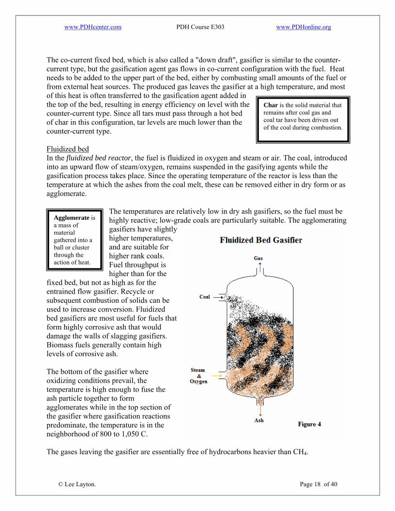
The co-current fixed bed, which is also called a "down draft", gasifier is similar to the counter-current type, but the gasification agent gas flows in co-current configuration with the fuel. Heat needs to be added to the upper part of the bed, either by combusting small amounts of the fuel or from external heat sources. The produced gas leaves the gasifier at a high temperature, and most of this heat is often transferred to the gasification agent added in the top of the bed, resulting in energy efficiency on level with the counter-current type. Since all tars must pass through a hot bed of char in this configuration, tar levels are much lower than the counter-current type. Fluidized bed In the fluidized bed reactor, the fuel is fluidized in oxygen and steam or air. The coal, introduced into an upward flow of steam/oxygen, remains suspended in the gasifying agents while the gasification process takes place. Since the operating temperature of the reactor is less than the temperature at which the ashes from the coal melt, these can be removed either in dry form or as agglomerate.
The temperatures are relatively low in dry ash gasifiers, so the fuel must be highly reactive; low-grade coals are particularly suitable. The agglomerating gasifiers have slightly higher temperatures, and are suitable for higher rank coals. Fuel throughput is higher than for the
fixed bed, but not as high as for the entrained flow gasifier. Recycle or subsequent combustion of solids can be used to increase conversion. Fluidized bed gasifiers are most useful for fuels that form highly corrosive ash that would damage the walls of slagging gasifiers. Biomass fuels generally contain high levels of corrosive ash. The bottom of the gasifier where oxidizing conditions prevail, the temperature is high enough to fuse the ash particle together to form agglomerates while in the top section of the gasifier where gasification reactions predominate, the temperature is in the neighborhood of 800 to 1,050 C. The gases leaving the gasifier are essentially free of hydrocarbons heavier than CH4.
© Lee Layton. Page 18 of 40
Agglomerate is a mass of material gathered into a ball or cluster through the action of heat.
Char is the solid material that remains after coal gas and coal tar have been driven out of the coal during combustion.
www.PDHcenter.com PDH Course E303 www.PDHonline.org
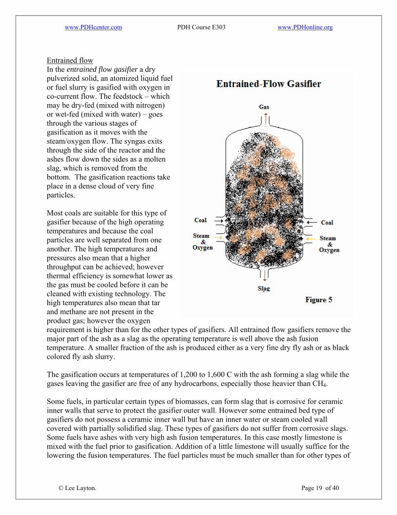
Entrained flowIn the entrained flow gasifier a dry pulverized solid, an atomized liquid fuel or fuel slurry is gasified with oxygen in co-current flow. The feedstock – which may be dry-fed (mixed with nitrogen) or wet-fed (mixed with water) – goes through the various stages of gasification as it moves with the steam/oxygen flow. The syngas exits through the side of the reactor and the ashes flow down the sides as a molten slag, which is removed from the bottom. The gasification reactions take place in a dense cloud of very fine particles. Most coals are suitable for this type of gasifier because of the high operating temperatures and because the coal particles are well separated from one another. The high temperatures and pressures also mean that a higher throughput can be achieved; however thermal efficiency is somewhat lower as the gas must be cooled before it can be cleaned with existing technology. The high temperatures also mean that tar and methane are not present in the product gas; however the oxygen requirement is higher than for the other types of gasifiers. All entrained flow gasifiers remove the major part of the ash as a slag as the operating temperature is well above the ash fusion temperature. A smaller fraction of the ash is produced either as a very fine dry fly ash or as black colored fly ash slurry. The gasification occurs at temperatures of 1,200 to 1,600 C with the ash forming a slag while the gases leaving the gasifier are free of any hydrocarbons, especially those heavier than CH4. Some fuels, in particular certain types of biomasses, can form slag that is corrosive for ceramic inner walls that serve to protect the gasifier outer wall. However some entrained bed type of gasifiers do not possess a ceramic inner wall but have an inner water or steam cooled wall covered with partially solidified slag. These types of gasifiers do not suffer from corrosive slags. Some fuels have ashes with very high ash fusion temperatures. In this case mostly limestone is mixed with the fuel prior to gasification. Addition of a little limestone will usually suffice for the lowering the fusion temperatures. The fuel particles must be much smaller than for other types of
© Lee Layton. Page 19 of 40

www.PDHcenter.com PDH Course E303 www.PDHonline.org
gasifiers. This means the fuel must be pulverized, which requires somewhat more energy than for the other types of gasifiers. By far the most energy consumption related to entrained bed gasification is not the milling of the fuel but the production of oxygen used for the gasification. The raw gas leaving a gasifier is cooled either by a heat exchanger while generating steam or is directly quenched with water if the gas contains particulates that are in the molten or semi-molten state. The cooled gas is purified by further treatment to remove the particulates, alkalis, chlorides as well as the nitrogen and sulfur compounds. An advantage with gasification is the sulfur may be recovered as salable elemental sulfur. Technologies are currently in the demonstration phase to clean gas without completely cooling it. The gas is kept above the dew point of water which eliminates the extensive waste water treatment typically required by gasification using "cold gas cleanup."
© Lee Layton. Page 20 of 40
www.PDHcenter.com PDH Course E303 www.PDHonline.org
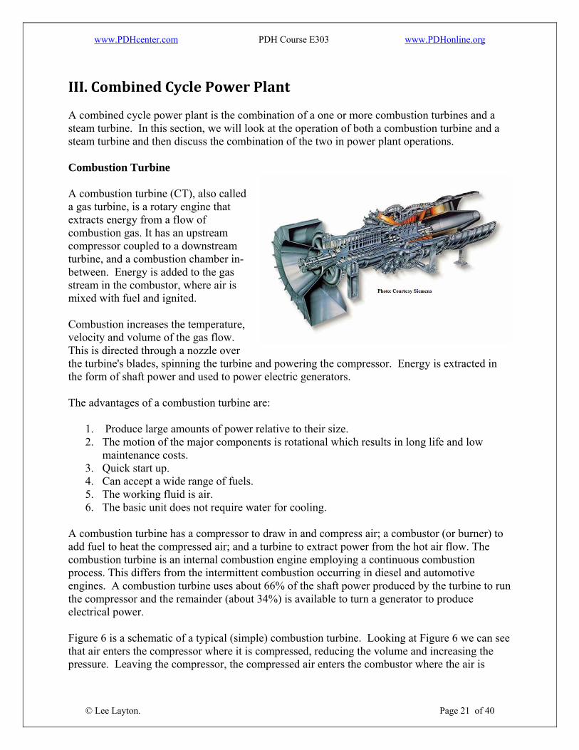
III. Combined Cycle Power Plant A combined cycle power plant is the combination of a one or more combustion turbines and a steam turbine. In this section, we will look at the operation of both a combustion turbine and a steam turbine and then discuss the combination of the two in power plant operations. Combustion Turbine A combustion turbine (CT), also called a gas turbine, is a rotary engine that extracts energy from a flow of combustion gas. It has an upstream compressor coupled to a downstream turbine, and a combustion chamber in-between. Energy is added to the gas stream in the combustor, where air is mixed with fuel and ignited. Combustion increases the temperature, velocity and volume of the gas flow. This is directed through a nozzle over the turbine's blades, spinning the turbine and powering the compressor. Energy is extrathe form of s
cted in haft power and used to power electric generators.
The advantages of a combustion turbine are:
1. Produce large amounts of power relative to their size. 2. The motion of the major components is rotational which results in long life and low
maintenance costs. 3. Quick start up. 4. Can accept a wide range of fuels. 5. The working fluid is air. 6. The basic unit does not require water for cooling.
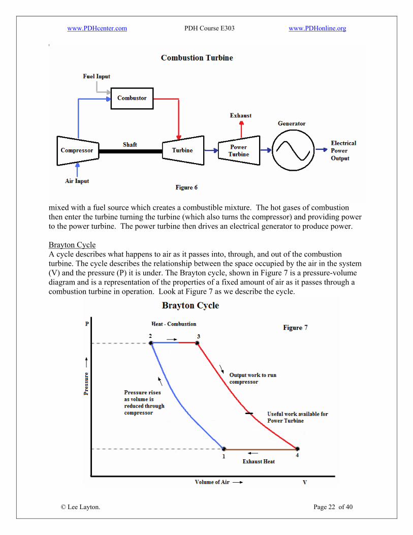
A combustion turbine has a compressor to draw in and compress air; a combustor (or burner) to add fuel to heat the compressed air; and a turbine to extract power from the hot air flow. The combustion turbine is an internal combustion engine employing a continuous combustion process. This differs from the intermittent combustion occurring in diesel and automotive engines. A combustion turbine uses about 66% of the shaft power produced by the turbine to run the compressor and the remainder (about 34%) is available to turn a generator to produce electrical power. Figure 6 is a schematic of a typical (simple) combustion turbine. Looking at Figure 6 we can see that air enters the compressor where it is compressed, reducing the volume and increasing the pressure. Leaving the compressor, the compressed air enters the combustor where the air is
© Lee Layton. Page 21 of 40
www.PDHcenter.com PDH Course E303 www.PDHonline.org
© Lee Layton. Page 22 of 40
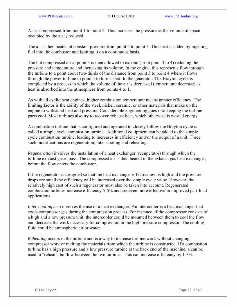
mixed with a fuel source which creates a combustible mixture. The hot gases of combustion then enter the turbine turning the turbine (which also turns the compressor) and providing power to the power turbine. The power turbine then drives an electrical generator to produce power. Brayton Cycle A cycle describes what happens to air as it passes into, through, and out of the combustion turbine. The cycle describes the relationship between the space occupied by the air in the system (V) and the pressure (P) it is under. The Brayton cycle, shown in Figure 7 is a pressure-volume diagram and is a representation of the properties of a fixed amount of air as it passes through a combustion turbine in operation. Look at Figure 7 as we describe the cycle.
www.PDHcenter.com PDH Course E303 www.PDHonline.org
Air is compressed from point 1 to point 2. This increases the pressure as the volume of space occupied by the air is reduced.
t pressure from point 2 to point 3. This heat is added by injecting el into the combustor and igniting it on a continuous basis.
rom point 3 to 4) reducing the ressure and temperature and increasing its volume. In the engine, this represents flow through
e means greater efficiency. The miting factor is the ability of the steel, nickel, ceramic, or other materials that make up the
alled a simple cycle combustion turbine. Additional equipment can be added to the simple
rator) through which the rbine exhaust gases pass. The compressed air is then heated in the exhaust gas heat exchanger,
e heat exchanger effectiveness is high and the pressure ops are small the efficiency will be increased over the simple cycle value. However, the
-load
lves the use of a heat exchanger. An intercooler is a heat exchanger that ols compressor gas during the compression process. For instance, if the compressor consists of
ay to increase turbine work without changing mpressor work or melting the materials from which the turbine is constructed. If a combustion
an be
The air is then heated at constanfu The hot compressed air at point 3 is then allowed to expand (fpthe turbine to a point about two-thirds of the distance from point 3 to point 4 where it flows through the power turbine to point 4 to turn a shaft to the generator. The Brayton cycle is completed by a process in which the volume of the air is decreased (temperature decrease) asheat is absorbed into the atmosphere from points 4 to 1. As with all cyclic heat engines, higher combustion temperaturliengine to withstand heat and pressure. Considerable engineering goes into keeping the turbine parts cool. Most turbines also try to recover exhaust heat, which otherwise is wasted energy. A combustion turbine that is configured and operated to closely follow the Brayton cycle is ccycle combustion turbine, leading to increases in efficiency and/or the output of a unit. Threesuch modifications are regeneration, inter-cooling and reheating. Regeneration involves the installation of a heat exchanger (recupetubefore the flow enters the combustor. If the regenerator is designed so that thdrrelatively high cost of such a regenerator must also be taken into account. Regenerated combustion turbines increase efficiency 5-6% and are even more effective in improved partapplications. Inter-cooling also invocoa high and a low pressure unit, the intercooler could be mounted between them to cool the flow and decrease the work necessary for compression in the high pressure compressor. The cooling fluid could be atmospheric air or water. Reheating occurs in the turbine and is a wcoturbine has a high pressure and a low pressure turbine at the back end of the machine, a cused to "reheat" the flow between the two turbines. This can increase efficiency by 1-3%.
© Lee Layton. Page 23 of 40
www.PDHcenter.com PDH Course E303 www.PDHonline.org
Heat Recovery ombustion turbines generate a large volume of very hot air. The exhaust is also high in oxygen
ared to other combustion exhaust streams, as only a small amount of oxygen is
lication, the turbine exhaust may supplemented by a duct burner.
rner located in the turbine exhaust stream. It has a very high iciency due to the high inlet air temperature, and is used to boost the total available thermal
er plants) waste all of their turbine exhaust, they have no thermal requirements. These plants generally use turbines with recuperators to
rbine, the lower the available thermal energy in the haust. Newer turbines with recuperators, and larger sized turbines, tend to have higher
Ccontent as comprequired by the combustor relative the total volume available. Depending on how much thermal energy is required for the appbe A duct burner is a direct fired gas bueffenergy. The turbine exhaust boosted by the duct burner is directed into the waste heat boiler, called the Heat Recovery Steam Generator (HRSG). Single or Simple Cycle electric plants (typical of peakas maximize their electrical efficiency. The higher the electrical efficiency of the tuexefficiencies. Efficiency Turbine efficiency and total capacity is highly variable with the inlet air temperature (ambient air
if no inlet air cooling is utilized) and local altitude/atmospheric conditions. In a
ycle turbines have an efficiency of 25% (smaller, unrecuperated) to 40% rger units with recuperators), when comparing fuel energy in, to electric energy out. The
ate efficiency based on the Heat Rate, use the formula,
Where,
= Combustion efficiency of the Brayton cycle, percent. e = BTU requirement, BTU’s.
rbine is 11,000 BTU, so the efficiency is,
temperaturenorthern climate, turbine capacity can fluctuate as must as 20% from summer to winter, due to cold, denser air. Single or Simple C(lastandard measurement is called the Heat Rate, or the BTUs input to make 1 kWh of electric output. To estim
ηb = 3,413 / Heat Rate * 100
ηbHeat Rat The typical heat rate for a combustion tu ηb = 3,413 / 11,000 * 100
© Lee Layton. Page 24 of 40
www.PDHcenter.com PDH Course E303 www.PDHonline.org
ηb = 31%. Environmental The primary emission concern of natural gas fired turbines is NOx, and in some cases CO and CO2. Because turbine combustors operate at a very high temperature, uncontrolled turbines produce high levels of NOx. A variety of controls have been developed in an attempt to lower NOx to the 9 ppm required by the strictest regulations. The most common control methods for NOx is water injection to reduce combustion temperature, and Selective Catalytic Reduction (SCR) an after-treatment to remove NOx. Steam Turbine Steam turbines are one of the most versatile and oldest prime mover technologies used to drive a generator. Most of the electricity in the United States is generated by conventional steam turbine power plants. The capacity of steam turbines can range from a fractional horsepower to more than 1,300 MW for large utility power plants. A steam turbine uses a separate heat source and does not directly convert a fuel source to electric energy. Steam turbines require a source of high pressure steam that is produced in a boiler or heat recovery steam generator. They have rather low electrical conversion efficiency, but are simple, durable, and have predictable performance characteristics. These systems use a liquid that evaporates when heated and expands to produce work, such as turning a turbine. The working fluid most commonly used is water, though other liquids can also be used. The thermodynamic cycle for the steam turbine is the Rankine cycle. The cycle is the basis for conventional power generating stations and consists of a heat source (boiler) that converts water to high pressure steam. The steam flows through the turbine to produce power. The steam exiting the turbine is condensed and returned to the boiler to repeat the process. A steam turbine consists of a stationary set of blades (called nozzles) and a moving set of adjacent blades (called buckets or rotor blades) installed within a casing. The two sets of blades work together such that the steam turns the shaft of the turbine and the connected load. A steam turbine converts pressure energy into velocity energy as it passes through the blades. The primary type of turbine used for central power generation is the condensing turbine. Steam exhausts from the turbine at sub-atmospheric pressures, maximizing the heat extracted from the steam to produce useful work.
© Lee Layton. Page 25 of 40
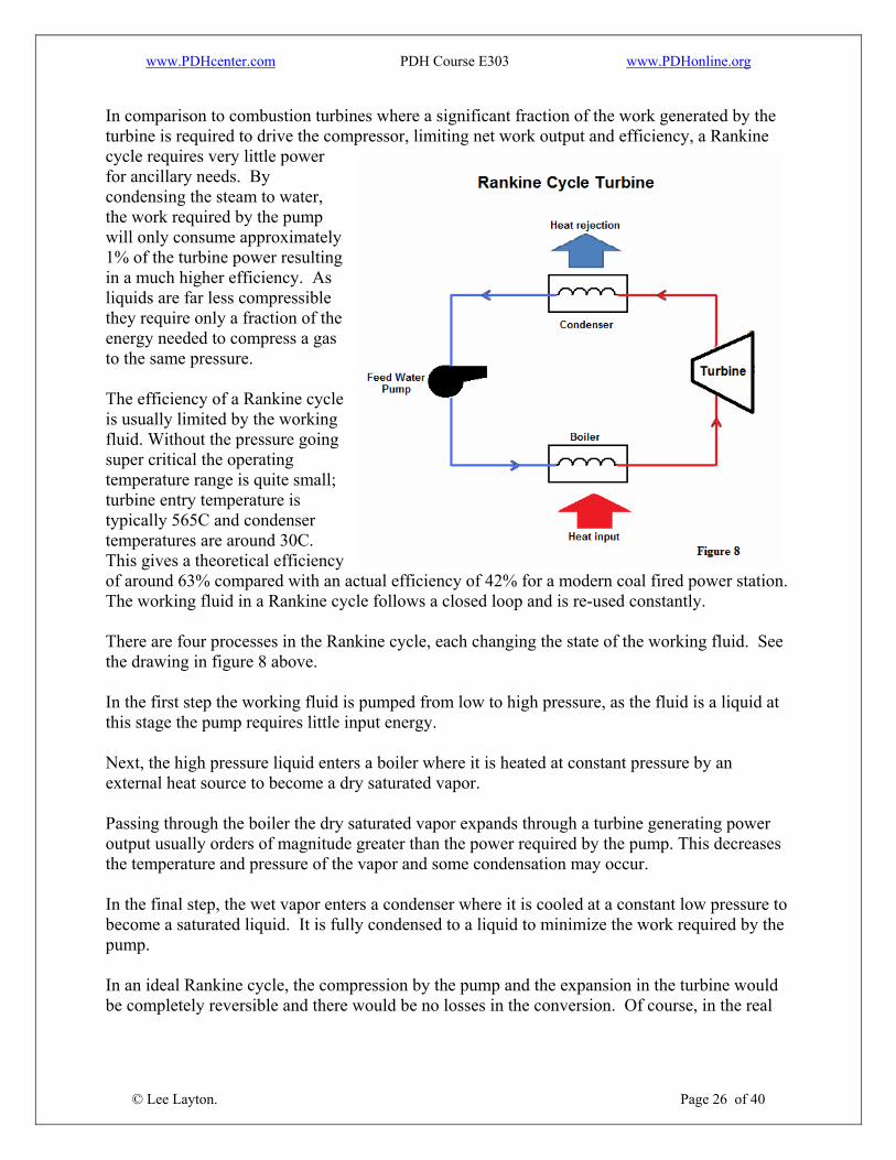
The Rankine cycle is a four-stage process. In the first stage, the working fluid is pumped into a boiler. While the fluid is in the boiler, an external heat source superheats the fluid. The hot water vapor then expands to drive a turbine. Once past the turbine, the steam is condensed back into liquid and recycled back to the pump to start the cycle all over again. Pump, boiler, turbine, and condenser are the four parts of a standard steam engine and represent each phase of the Rankine cycle. The following figure is a schematic of a Rankine cycle system.
www.PDHcenter.com PDH Course E303 www.PDHonline.org
In comparison to combustion turbines where a significant fraction of the work generated by the turbine is required to drive the compressor, limiting net work output and efficiency, a Rankine cycle requires very little power for ancillary needs. By condensing the steam to water, the work required by the pump will only consume approximately 1% of the turbine power resulting in a much higher efficiency. As liquids are far less compressible they require only a fraction of the energy needed to compress a gas to the same pressure. The efficiency of a Rankine cycle is usually limited by the working fluid. Without the pressure going super critical the operating temperature range is quite small; turbine entry temperature is typically 565C and condenser temperatures are around 30C. This gives a theoretical efficiency of around 63% compared with an actual efficiency of 42% for a modern coal fired power station. The working fluid in a Rankine cycle follows a closed loop and is re-used constantly. There are four processes in the Rankine cycle, each changing the state of the working fluid. See the drawing in figure 8 above. In the first step the working fluid is pumped from low to high pressure, as the fluid is a liquid at this stage the pump requires little input energy. Next, the high pressure liquid enters a boiler where it is heated at constant pressure by an external heat source to become a dry saturated vapor. Passing through the boiler the dry saturated vapor expands through a turbine generating power output usually orders of magnitude greater than the power required by the pump. This decreases the temperature and pressure of the vapor and some condensation may occur. In the final step, the wet vapor enters a condenser where it is cooled at a constant low pressure to become a saturated liquid. It is fully condensed to a liquid to minimize the work required by the pump. In an ideal Rankine cycle, the compression by the pump and the expansion in the turbine would be completely reversible and there would be no losses in the conversion. Of course, in the real
© Lee Layton. Page 26 of 40
www.PDHcenter.com PDH Course E303 www.PDHonline.org
world the process does generate losses, which increases the power required by the pump and decreases the power generated by the turbine. The efficiency of the steam turbine will be limited by water droplet formation. As the water condenses, water droplets hit the turbine blades at high speed causing pitting and erosion, gradually decreasing the efficiency of the turbine. The easiest way to overcome this problem is by superheating the steam. Two main variations of the basic Rankine cycle: Rankine cycle with reheat and Regenerative Rankine cycles. A Rankine cycle with reheat uses two turbines in series. The first accepts vapor from the boiler at high pressure. After the vapor has passed through the first turbine, it re-enters the boiler and is reheated before passing through a second, lower pressure turbine. This prevents the vapor from condensing during its expansion which can seriously damage the turbine blades, and improves the efficiency of the cycle. The other variation is the regenerative Rankine cycle. With this process, the working fluid is heated by steam tapped from the hot portion of the cycle after emerging from the condenser. This increases the average temperature of heat addition which in turn increases the thermodynamic efficiency of the cycle. Simple Cycle Combustion Turbine (SCCT) In electric power generation, a combustion turbine power plant is called a Simple Cycle Combustion Turbine (SCCT) and is simply a combustion turbine. It differs from a combined cycle machine in that it has no provision for waste heat recovery. The main advantage of an SCCT is the ability for it to "cycle" or be turned on and off within minutes. This is unlike many other power plants that may have a minimum time of being online once started. This "Minimum Up" is a common term in the power industry when referring to this requirement. Due to its cycling ability SCCTs are useful for supplying power during peak demand. Therefore they are usually used as peaking power plants, which can operate from several hours per day to a couple dozen hours per year, depending on the electricity demand and the generating capacity of the region. A typical large simple cycle combustion turbine may produce 100 to 300 megawatts of power and have 30% thermal efficiency. SCCTs require smaller capital investment than either coal or nuclear power plants and can be scaled to generate small or large amounts of power. Also, the actual construction process can take as little as several weeks to a few months, compared to years for base load power plants. A simple cycle combustion turbine has a lower thermal efficiency than a combined cycle machine.
© Lee Layton. Page 27 of 40
www.PDHcenter.com PDH Course E303 www.PDHonline.org
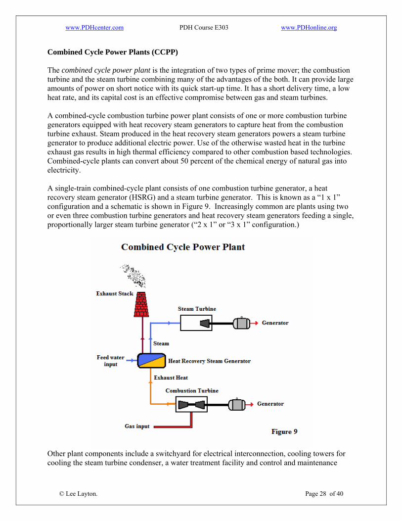
Combined Cycle Power Plants (CCPP) The combined cycle power plant is the integration of two types of prime mover; the combustion turbine and the steam turbine combining many of the advantages of the both. It can provide large amounts of power on short notice with its quick start-up time. It has a short delivery time, a low heat rate, and its capital cost is an effective compromise between gas and steam turbines. A combined-cycle combustion turbine power plant consists of one or more combustion turbine generators equipped with heat recovery steam generators to capture heat from the combustion turbine exhaust. Steam produced in the heat recovery steam generators powers a steam turbine generator to produce additional electric power. Use of the otherwise wasted heat in the turbine exhaust gas results in high thermal efficiency compared to other combustion based technologies. Combined-cycle plants can convert about 50 percent of the chemical energy of natural gas into electricity. A single-train combined-cycle plant consists of one combustion turbine generator, a heat recovery steam generator (HSRG) and a steam turbine generator. This is known as a “1 x 1” configuration and a schematic is shown in Figure 9. Increasingly common are plants using two or even three combustion turbine generators and heat recovery steam generators feeding a single, proportionally larger steam turbine generator (“2 x 1” or “3 x 1” configuration.)
© Lee Layton. Page 28 of 40
Other plant components include a switchyard for electrical interconnection, cooling towers for cooling the steam turbine condenser, a water treatment facility and control and maintenance
www.PDHcenter.com PDH Course E303 www.PDHonline.org
facilities. Additional peaking capacity can be obtained by use of various power augmentation features, including inlet air chilling and duct firing (direct combustion of natural gas in the heat recovery steam generator). Though the incremental thermal efficiency of duct firing is lower than that of the base combined-cycle plant, the incremental cost is low and the additional electrical output can be valuable during peak load periods. Combustion turbines can operate on either gaseous or liquid fuels. With the exception of IGCC plants, pipeline natural gas is the fuel of choice because of historically low and relatively stable prices, deliverability and low air emissions. Distillate fuel oil can be used as a backup fuel, however, its use for this purpose has become less common in recent years because of additional emissions of sulfur oxides, deleterious effects on catalysts for the control of nitrogen oxides and carbon monoxide, the periodic testing required to ensure proper operation on fuel oil and increased turbine maintenance associated with fuel oil operation. The principal environmental concerns associated with gas-fired combined-cycle combustion turbines are emissions of nitrogen oxides (NOx) and carbon monoxide (CO). Nitrogen oxide abatement is accomplished by use of “dry low-NOx” combustors and a selective catalytic reduction system within the HSRG. Limited quantities of ammonia are released by operation of the NOx SCR system. CO emissions are typically controlled by use of an oxidation catalyst within the HSRG. No special controls for particulates and sulfur oxides are used since only trace amounts are produced when operating on natural gas. Fairly significant quantities of water are required for cooling the steam condenser. Water consumption can be reduced by use of dry (closed-cycle) cooling, though with cost and efficiency penalties. Gas-fired combined-cycle plants produce less carbon dioxide per unit energy output than other fossil fuel technologies because of the relatively high thermal efficiency of the technology and the high hydrogen-carbon ratio of methane. Because of high thermal efficiency, low initial cost, high reliability, relatively low gas prices and low air emissions, combined-cycle combustion turbines are an attractive choice for intermediate loads. Other beneficial features include significant operational flexibility, the availability of relatively inexpensive power augmentation for peak period operation and relatively low carbon dioxide production. Water consumption for power plant condenser cooling appears to be an issue of increasing importance. Significant reduction in plant water consumption can be achieved by the use of closed-cycle (dry) cooling, but at a cost and performance penalty. Carbon dioxide, a greenhouse gas, is an unavoidable product of combustion of any power generation technology using fossil fuel. The carbon dioxide production of a gas-fired combined-cycle plant on a unit output basis is much lower than that of other fossil fuel technologies.
© Lee Layton. Page 29 of 40
By combining both gas and steam cycles, high input temperatures and low output temperatures can be achieved. The efficiency of the cycles are additive because they are powered by the same fuel source. So, a combined cycle plant has a thermodynamic cycle that operates between the gas-turbine's high firing temperature and the waste heat temperature from the condensors of the
www.PDHcenter.com PDH Course E303 www.PDHonline.org
steam cycle. The actual efficiency is higher than that of either plant on its own. The efficiency of a combined cycle plant can be determined fairly simply by the following formula.
ηCC = [ηB + ηB R – (ηB * ηR )] * 100 Where, ηCC = Efficiency of the combined cycle power plant, percent. ηB = Efficiency of the Brayton cycle (combustion turbine), decimal value. ηR = Efficiency of the Rankine cycle (steam plant), decimal value. For instance, what is the efficiency of a combined cycle plant where the combustion turbine efficiency is 35% and the steam plant efficiency is 30%? ηCC = [0.35 + 0.30 – (0.35 * 0.30) ] * 100 ηCC = 54.5% Actually the overall efficiency will be less than this theoretical value because of losses in the system, but as you can see, the efficiency of the combined plant is much greater than the efficiency of either the combustion turbine or the steam plant. Heat recovery steam generator As previously mentioned, a heat recovery steam generator is a key component of a combined cycle power plant. A heat recovery steam generator (HRSG) is a heat exchanger that recovers heat from the hot gas stream of a combustion turbine then it produces steam that can be used to drive a steam turbine. This combination produces electricity more efficiently than either the gas turbine or steam turbine alone. A heat recovery steam generator consists of an evaporator, superheater, and economizer. Each section has a steam drum and an evaporator section where water is converted to steam. This steam then passes through superheaters to raise the temperature and pressure past the saturation point. The economizer is a heat exchanger. In a HRSG, the economizer is used to capture the waste heat from the boiler stack gases and transfer it to the boiler feedwater. This raises the temperature of the boiler feedwater thus lowering the needed energy input. Some heat recovery steam generators include supplemental, or duct firing. These additional burners provide additional energy to the heat recovery steam generator, which produces more steam and hence increases the output of the steam turbine. Generally, duct firing provides electrical output at lower capital cost. It is therefore often utilized for peaking. Heat recovery steam generators can also have diverter valves to regulate in the inlet flow into the heat recovery steam generator. This allows the gas turbine to continue to operate when there is no steam demand or if the heat recovery steam generator needs to be taken offline.
© Lee Layton. Page 30 of 40

www.PDHcenter.com PDH Course E303 www.PDHonline.org
Emissions controls may also be located in the heat recovery steam generator. Some may contain a Selective Catalytic Reduction (SCR) system to reduce nitrogen oxides and a catalyst to remove carbon monoxide. The inclusion of an SCR dramatically affects the layout of the heat recovery steam generator. NOx catalyst performs best in temperatures between 650°F and 750°F. This usually means that the evaporator section of the heat recovery steam generator will have to be split and the SCR placed in between the two sections. Some low temperature NOx catalysts have recently come to market that allows for the SCR to be placed between the Evaporator and Economizer sections.
© Lee Layton. Page 31 of 40
www.PDHcenter.com PDH Course E303 www.PDHonline.org
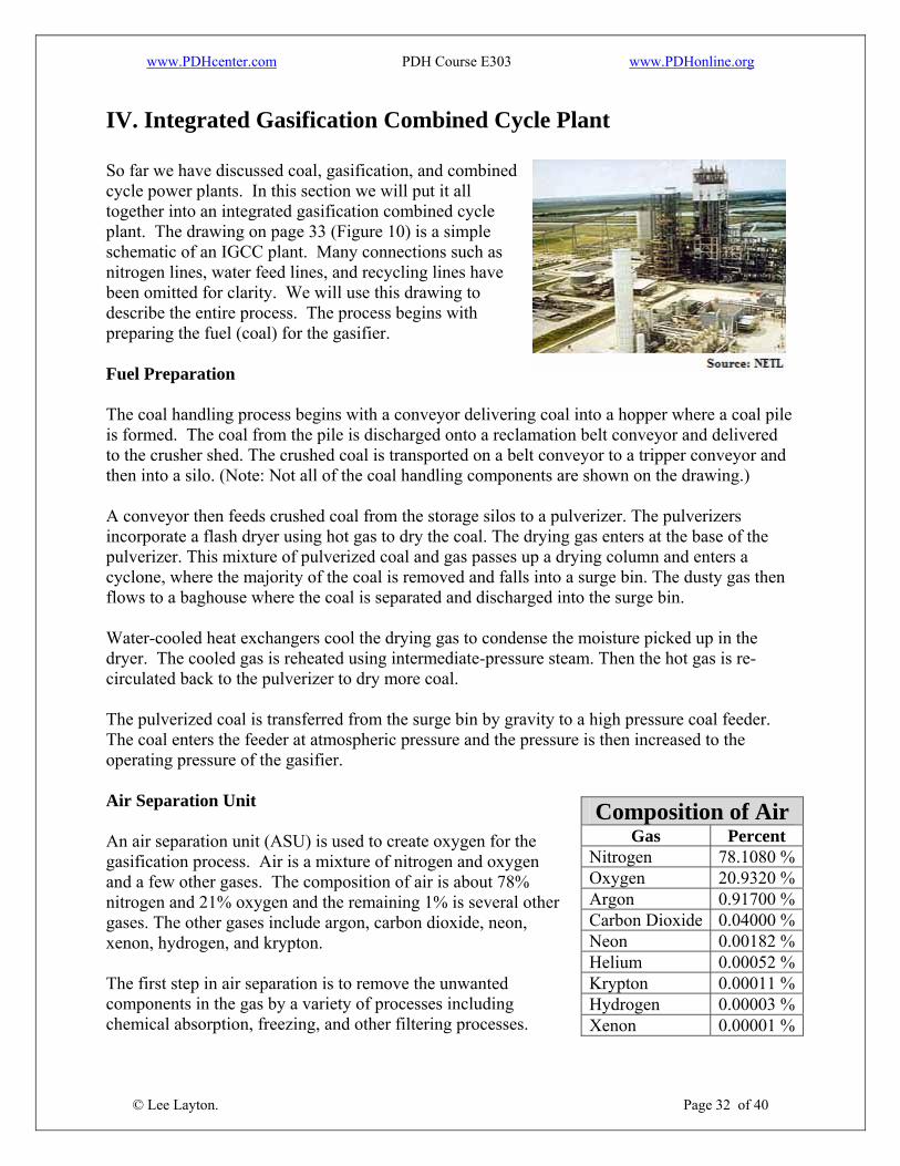
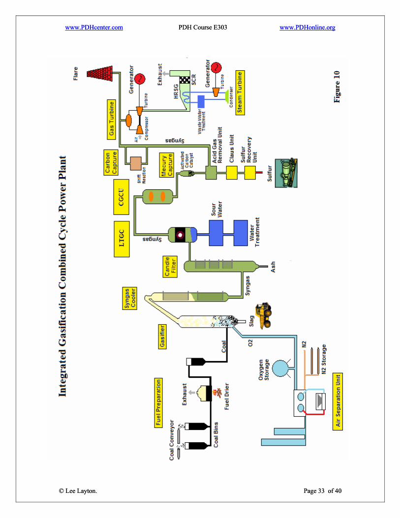
IV. Integrated Gasification Combined Cycle Plant So far we have discussed coal, gasification, and combined cycle power plants. In this section we will put it all together into an integrated gasification combined cycle plant. The drawing on page 33 (Figure 10) is a simple schematic of an IGCC plant. Many connections such as nitrogen lines, water feed lines, and recycling lines have been omitted for clarity. We will use this drawing to describe the entire process. The process begins with preparing the fuel (coal) for the gasifier. Fuel Preparation The coal handling process begins with a conveyor delivering coal into a hopper where a coal pile is formed. The coal from the pile is discharged onto a reclamation belt conveyor and delivered to the crusher shed. The crushed coal is transported on a belt conveyor to a tripper conveyor and then into a silo. (Note: Not all of the coal handling components are shown on the drawing.) A conveyor then feeds crushed coal from the storage silos to a pulverizer. The pulverizers incorporate a flash dryer using hot gas to dry the coal. The drying gas enters at the base of the pulverizer. This mixture of pulverized coal and gas passes up a drying column and enters a cyclone, where the majority of the coal is removed and falls into a surge bin. The dusty gas then flows to a baghouse where the coal is separated and discharged into the surge bin. Water-cooled heat exchangers cool the drying gas to condense the moisture picked up in the dryer. The cooled gas is reheated using intermediate-pressure steam. Then the hot gas is re-circulated back to the pulverizer to dry more coal. The pulverized coal is transferred from the surge bin by gravity to a high pressure coal feeder. The coal enters the feeder at atmospheric pressure and the pressure is then increased to the operating pressure of the gasifier. Air Separation Unit Composition of Air
Gas Percent Nitrogen 78.1080 %Oxygen 20.9320 %Argon 0.91700 %Carbon Dioxide 0.04000 %Neon 0.00182 %Helium 0.00052 %Krypton 0.00011 %Hydrogen 0.00003 %Xenon 0.00001 %
An air separation unit (ASU) is used to create oxygen for the gasification process. Air is a mixture of nitrogen and oxygen and a few other gases. The composition of air is about 78% nitrogen and 21% oxygen and the remaining 1% is several other gases. The other gases include argon, carbon dioxide, neon, xenon, hydrogen, and krypton. The first step in air separation is to remove the unwanted components in the gas by a variety of processes including chemical absorption, freezing, and other filtering processes.
© Lee Layton. Page 32 of 40
www.PDHcenter.com PDH Course E303 www.PDHonline.org
www.PDHcenter.com PDH Course E303 www.PDHonline.org
© Lee Layton. Page 33 of 40
© Lee Layton. Page 33 of 40
www.PDHcenter.com PDH Course E303 www.PDHonline.org
Next the air is compressed, which creates heat. The compressed air is then cooled to a temperature of minus 180°C. As it expands in the separation columns, the air cools down still further. As a result the air liquefies to some extent (the temperature being lower than the boiling point). A separation column is used to separate air into its components. The process involves the liquid mixture trickling down to meet the rising stream of gas. The liquid collects on the trays in the column, and is penetrated by the vapor bubbles from beneath. Oxygen, with its higher boiling point (-183C) condenses out of the stream of gas. The drops of liquid, on the other hand, give rise for preference to evaporating nitrogen, with its lower boiling point of -196°C. Gaseous nitrogen collects at the top of the separation column, while liquid oxygen collects at the bottom of the column. The oxygen at the bottom is vaporized, while nitrogen in liquid form is introduced at the top of the column. This process is continued as long as required to reach the desired level of purity. The separation column is equipped with additional aggregates to capture argon, neon, helium, krypton and xenon. The oxygen is used in the gasifier and the nitrogen is used in various applications in the IGCC plant. Gasifier The gasifier in this example is a dry-feed, oxygen-fed, entrained-flow slagging type, which is the most common gasifier for IGCC plants. The coal is pulverized and dried prior to being fed into the gasifier using nitrogen as the transport gas. Coal, oxygen and steam enter the gasifier through horizontally opposed burners. Syngas is produced from high temperature gasification reactions and flows upwardly with some entrained particulates composed of ash and a small quantity of unreacted carbon. The high reactor temperature converts the remaining ash into a molten slag, which flows down the walls of the gasifier and passes into a slag quench bath. The reactor temperature is controlled by using part of the heat of reaction to generate high pressure steam in the membrane walls of the gasifier. The syngas is quenched at the reactor exit with cooled recycled fuel gas to lower the temperature below the melting point of the ash to prevent sticky solids entering the syngas cooler. Syngas Cooler The syngas stream leaving the gasifier passes to a syngas cooler that lowers the syngas temperature to the operating temperature of the candle filter system. The syngas cooler consists of three stages, an evaporator, a superheater, and an economizer. The evaporator utilizes a natural circulation steam drum operating at above steam turbine inlet pressure and at saturated temperature. The steam raised in the evaporator is passed to a superheater where it is heated to the steam turbine inlet temperature. This steam is mixed with the superheated steam exiting the HRSG in the combined cycle power plant before passing into the steam turbine. Boiler feed water enters the economizer and is heated to near saturation before entering the steam drum.
© Lee Layton. Page 34 of 40

www.PDHcenter.com PDH Course E303 www.PDHonline.org
Candle Filter The Candle Filters are pressure filters and provide efficient low moisture cake filtration. A candle filter consists of three major components: The vessel, filtering elements, and a cake discharge mechanism. The Vessel The feed to the filter is always positioned at the lower portion of the vessel to allow upflow of the incoming slurry. This is imperative for maintaining fast settling solids in a homogeneous suspension and thus ensure that uniform cakes are formed. An uneven cake thickness that tapers up interferes with the efficiency of cake washing and reduces the effective volume of the cake that accumulates on the filtering elements. The filtrate outlet from each row of candles is connected to a horizontal header and all headers deliver the filtrate through valves to a collecting manifold for further processing. The arrangement of headers enables individual control on the flow in each row of candles so that increasing flow rate per element during cake formation, sequential cake discharge or backwashing may be used for flexibility of
eration. op The Candles The filter elements are called candles and consist of the filter core and the filtering mediumcandle core serves for filtrate passage and to support the filter medium. The core may be a bundle of perforated tubes or ball shaped packing material that is contained in a coarse mesh screen sleeve. In the majority of applications the process requires to empty the elements from filtrate at the end of the filtration or washing cycle. This is achieved by inserting a pipe in the middle of the core to fully displace the filtr
. The
ate during air or gas purging from the bottom of the lement and upwards towards the header.
ted materials nd weaves, mono and multifilament yarns, micron sizes and air permeabilities.
e The available types of filter medium are very diverse such as porous ceramics, sintered metal tubes, expanded sheets, woven mesh screens or synthetic filter cloths in sophisticaa The Cake Discharge Mechanism For cakes that discharge readily a snap blow from the backside of the medium is sufficient to
lease the cake.
so are used to monitor the cake thickness and transmit a signal to turn off the slurry feed
mp.
re The major difficulty in discharging arises when the clearance between the cake surfaces closessensorspu
© Lee Layton. Page 35 of 40
www.PDHcenter.com PDH Course E303 www.PDHonline.org
Low Temperature Gas Cooling
to
mmonia is assumed to be in e scrubber water discharge which is sent to a water treatment unit.
h g the gasifier. The remaining fuel gas, 70%, is sent to the CGCU
ection for sulfur removal.
l gas from e downstream CGCU process and for heating boiler feed water in the steam cycle.
oval The combined water flow
arbon
t hydrocarbons, which pass to e vent gas recycle header.
S s
scharges to the steam-eated ammonia stripper to produce a concentrated ammonia solution.
s,
used in SCR units. Any excess anhydrous ammonia can be ld into the commercial market.
old Gas Clean up Unit
up unit (CGCU) employs a MDEA/Claus/SCOT process for cleanup and lfur recovery.
The syngas from the candle filter enters a low temperature gas cooling section (LTGC) which consists of several heat exchangers, catalytic hydrolyzer, and a water scrubber. The syngas is initially cooled to 230C and sent to the hydrolyzer which converts the carbonyl sulfide (COS)hydrogen sulfide. The gas stream is further cooled to 100C before entering a water scrubber which reduces the temperature to 40C. Any hydrogen chloride and ath A portion of the cooled fuel gas stream, approximately 30%, is split off and recycled to quencthe hot syngas stream exitins The heat recovered in the heat exchanger network is used in reheating the cleaned fueth The water condensed from the syngas by the coolers, and water produced in the Sulfur Remprocess is collected and sent to the Sour Water Treatment plant.passes to a filter to remove particulate and an activated cbed to remove heavy metals and organic material. The ammonia in the water retains most of the dissolved H2S and the gas released is mainly lighth Next, the sour water is heated in a stripped-water recuperator and passed to the steam-heated H2stripper where H2S, hydrogen cyanide (HCN), and CO2
are released and passed to the vent garecycle header. The syngas stream is compressed and injected into the oxidation zone of the gasifier where the HCN is destroyed. The water from the H2S stripper di
Sour Water is water containing acid
h The concentrated ammonia solution is further processed in two additional steam-heated stripperthe first releasing any remaining dissolved H2S into the vent gas recycle header and the second increasing the ammonia concentration to 99.7%. The ammonia produced is commercial-grade anhydrous ammonia which can be so C The cold gas cleansu MDEA In the MDEA step, the cooled gas from the gas cooling section enters an absorber where it comes into contact with the MDEA (amine) solvent. As it moves through the absorber, almost all of the H S and a portion of the CO are removed. The solute-rich MDEA solvent exits the absorber is heated by the solute-lean solvent from the stripper in a heat exchanger before entering the
2 2 and
© Lee Layton. Page 36 of 40
compounds, such as H2S.
www.PDHcenter.com PDH Course E303 www.PDHonline.org
stripping unit. Acid gases from the top of the stripper are sent to the Claus/SCOT unit for sulfur recovery. The lean MDEA solvent exits the bottom of the stripper and is cooled through severaheat exchange
l rs. It is then cleaned in a filtering unit and sent to a storage tank before the next
ycle begins. c Claus process The Claus process converts toxic sulphur compounds to harmless elemental sulphur. The heat oreaction of this conversion is used to raise steam and contributes to the efficiency of the power plant. The Claus process is carried out in two stages. In the thermal stage, about one-quarter ofthe gases from the MDEA unit, which exits at 70C, are mixed with the recycle acid gases from the SCOT unit and are burned in the first furnace. In the catalyst stage the remaining acid gases are added to the second-sta
f
ge furnace, where the H2S and SO2 react in the presence of a catalyst form elemental sulfur.
ures above 850C such that lemental sulfur precipitates in the downstream process gas cooler.
rther combustible contents apart from H2S are burned in lances surrounding a central muffle.
bons are
s is controlled such that in total one-third of all ydrogen sulfide (H2S) is converted to SO2.
e or
cess step. The condensed sulfur is removed at the gas utlet section of the process gas cooler.
d 2 formed during
ombustion in the reaction furnace, and results in gaseous, elemental sulfur.
t unit is added downstream of the Claus plant, only
o catalytic stages are usually installed.
nt
to In the thermal step, hydrogen sulfide-laden gas reacts in at temperate The H2S-content and the concentration of other combustible components (hydrocarbons or ammonia) determine the location where the feed gas is burned. Claus gases (acid gas) with no fu Gases containing ammonia, such as the gas from the sour water stripper, or hydrocarconverted in the burner. Sufficient air is injected for the complete combustion of all hydrocarbons and ammonia. Air to the acid gah The separation of the combustion processes ensures an accurate dosage of the required air volume needed as a function of the feed gas composition. To reduce the process gas volumobtain higher combustion temperatures, the air requirement can also be accomplished by injecting pure oxygen. Usually, 60 to 70% of the total amount of elemental sulfur produced in the process is obtained in the thermal proo The Claus reaction continues in the catalytic step with activated alumina or titanium dioxide, anserves to boost the sulfur yield. The hydrogen sulfide (H2S) reacts with the SOc The catalytic recovery of sulfur consists of three sub steps: heating, catalytic reaction and cooling plus condensation. These three steps are normally repeated a maximum of three times.Where an incineration or tail-gas treatmentw
© Lee Layton. Page 37 of 40
The first process step in the catalytic stage is the process gas heating. It is necessary to prevesulfur condensation in the catalyst bed, which can lead to catalyst fouling. The required bed operating temperature in the individual catalytic stages is achieved by heating the process gas in
www.PDHcenter.com PDH Course E303 www.PDHonline.org
a reheater until the desired operating bed temperature is reached. Several methods of reheating are e
s gas) and the bypass (hot gas) from the first pass of the Waste heat boiler.
• hangers: whereby the cooled gas from the process gas cooler is indirectly heated from the hot gas coming out of an upstream catalytic reactor in a gas-to-gas
about 330C. The igh temperature in the first stage also helps to hydrolyze COS and CS2, which is formed in the
the sulfur condenser, the process gas coming from the catalytic reactor is cooled to around
from the process gas cooler, the sulfur condensers and from e final sulfur separator are routed to the degassing unit, where the gases (primarily H2S)
till containing combustible components and sulfur ompounds (H2S, H2 and CO) is either burned in an incineration unit or further desulfurized in a
gas treatment unit.
us d in industry:
• Hot gas bypass: which involves mixing the two process gas streams from the process gacooler (cold
• Indirect Steam reheaters: the gas can also be heated with high pressure steam in a heat exchanger. Gas/Gas Exc
exchanger. The typically recommended operating temperature of the first catalyst stage is hfurnace and would not otherwise be converted in the modified Claus process. In130C. The condensation heat is used to generate steam at the shell side of the condenser. Before storage, liquid sulfur streams thdissolved in the sulfur are removed. The tail gas from the Claus process scdownstream tail SCOT process The Shell Claus off-gas treatment (SCOT) process is used to clean up Claus sulphur recovery
he SCOT unit treats the tail-gas of a Claus unit so that the sulphur in the tail gas can be
ail gas is heated to a suitable reaction temperature with hydrogen or a mixture of hydrogen nd carbon monoxide. The hydrogen necessary for the reaction is naturally available in the tail
it is cooled during steam generation. The gas from e waste heat boiler cools and conditions further in a column that removes surplus water. The
n amine absorber column extracts the hydrogen sulphide from the gas stream. The hydrogen cled to the Claus unit.
plant tail-gas streams to over 99.8%. Trecovered with an amine solvent and recycled into the Claus unit. The tagas. The combined gas stream passes over a catalyst where sulphur dioxide and other sulphur species such as carbonyl sulphide, carbon disulphide and sulphur are converted to hydrogen sulphide. The gas passes into a waste heat boiler wherethwater is then sent to the sour-water stripper. Asulphide is then recy
© Lee Layton. Page 38 of 40
www.PDHcenter.com PDH Course E303 www.PDHonline.org
Mercury Capture Mercury can be effectively removed by using a sulfinated activated carbon. The process
ry in the syngas fuel into its elemental form.
e CO2 from flue gases after they are burned or eating the fuels to remove their carbon content leaving a hydrogen-rich fuel. The latter is
involves the removal of all or part of the carbon content of a fuel efore burning it. The main way in which this is done is by reforming the gas with steam, to
nd the of CO2 means that less powerful solvents are needed, that in turn require
ss energy to restore. This makes the capture of the CO2 more energy efficient and thus
s
to produce CO2 and more hydrogen. The products are thus CO2 nd hydrogen gas. The proportion of CO2 is high compared to those in conventional flue gases
the cycle. Condensate from the steam turbine condenser can be used r cooling in the gasifier. Also an IGCC plant needs an alternate fuel source for startup and
uring gasifier outages.
converts the mercu Carbon Capture Carbon capture can occur either by capturing thtrreferred to as pre-combustion carbon capture. Pre-combustion carbon capture bproduce CO2 and hydrogen. Pre-combustion techniques yield much higher concentrations of CO2 than are present in conventional flue gases, and at higher pressure. This yields two advantages for the purpose of capturing the CO2: the volume of gas being treated is lower, thus reducing capital costs; ahigher concentration lepotentially cheaper. In pre-combustion carbon capture the fuel is reacted with oxygen and in some cases steam. Thigives rise to a mixture consisting mainly of carbon monoxide (CO) and hydrogen (H2). The hydrogen/ CO mixture is then passed through a catalytic reactor known as a “shift converter.” There the CO reacts with steama(about 40%.) Combined Cycle Section The combined cycle power unit of an IGCC plant was thoroughly discussed in the previous section. However, a few additional points are worth mentioning. An IGCC plant has other interconnections to the gasification section that are not normally found in a traditional combined cycle power plant. For instance, nitrogen is supplied from the ASU to the combustor to aid in combustion and compressed air from the combustion turbine is supplied to the ASU. In additionto the steam from the HRSG, waste steam from the gasifier is supplied to the steam turbine toincrease the efficiency offod
© Lee Layton. Page 39 of 40
www.PDHcenter.com PDH Course E303 www.PDHonline.org
Summary Combining a coal gasification plant with a combined cycle power plant has the potential to provide an environmentally friendly method to continue to use coal as a generation fuel sourc
IGCC plants hold the promise of high thermal efficiency, but they have not delivered on the
e.
promised efficiencies. Hoenvironmental benefits of fired power plants.
Copyright © 2008 Lee . All Rights Reserved.
+++
wever, in spite of the lower than expected efficiencies, the IGCC may make it the choice for future coal-
© Lee Layton. Page 40 of 40
Layton