application tooling - te.com application tooling /// magnet wire tooling solutions from te...
TRANSCRIPT

TE APPLICATION TOOLING /// MAGNET WIRE TOOLING SOLUTIONS FROM TE CONNECTIVITY
APPLICATIONTOOLINGFOR MAGNET WIRE PROCESSINGFROM TE Connectivity (TE)

TE APPLICATION TOOLING /// MAGNET WIRE TOOLING SOLUTIONS FROM TE CONNECTIVITY PAGE 2
APPLICATION TOOLING FOR MAGNET WIRE PROCESSING
Inserter for MAG-MATE and SIAMEZE Terminals
AMPLIVAR Product Terminator (APT)
AMP 5/K-40 Thru Splice Terminator

PAGE 3TE APPLICATION TOOLING /// MAGNET WIRE TOOLING SOLUTIONS FROM TE CONNECTIVITY
MAG-MATE Terminals Standard .187 and .300 MAG-MATE Terminals
(Product Specification 108-2012)
Standard .500 Box MAG-MATE Terminals
(Product Specification 108-2053)
Slim Line MAG-MATE Terminals
(Product Specification 108-1484)
Mini MAG-MATE Terminals
(Product Specification 108-2016)
See also Catalog 82221
(Magnet Wire Terminals and Termination Systems)
AMPLIVAR Splices 9 Serrations - Pigtail Type
7 Serrations - Pigtail Type
5 Serrations - Pigtail Type
5 Serrations - Pigtail Type
Miniature Splice - Pigtail Type
See also Catalog 82221
SIAMEZE Terminals Standard Range SIAMEZE
(Product Specification 108-2085 )
High Temperature Standard Range SIAMEZE
(Product Specification 108-2293 )
Fine Range SIAMEZE
(Product Specification 108-2244 )
Medium Range SIAMEZE
(Product Specification 108-2239
Heavy Range SIAMEZE
(Product Specification 108-2316 )
See also Catalog 82221
BY USE OF THESE TOOLS TE MAGNET WIRE TERMINALS ARE APPLIED, SEE THE FOLLOWING EXAMPLES:

TE APPLICATION TOOLING /// MAGNET WIRE TOOLING SOLUTIONS FROM TE CONNECTIVITY PAGE 4
APPLICATION TOOLING FOR MAGNET WIRE PROCESSING
MAG-MATE Insertion Equipment• Semi-automatic machine for integration into
a manual workstation or production line
• The insertion machine can be installed horizontally
or vertically according to the requirements
• Separate control cabinet
• Separate touch panel
• Pneumatically operated, compressed air 6 bars
• Insertion tools driven by compressed air cylinders
Technical Data:
• Weight: app. 17 kg
• Weight with Z axis movement: app. 22 kg
• Dimensions of inserter (D x W x H):
600 mm x 220 mm x 165 mm
(200 with Z axis movement)
• Diameter of contact reel: app. 630 mm
• Dimensions of control cabinet (D x W x H):
210 mm x 380 mm x 480 mm (app)
• Power supply: 230 V, 50Hz, 6 A
• Sound level: < 70 db(A)
• Compressed air supply : 6 bars
• Compressed air connection: 1/8 “
• Air consumption (l/cycle): app. 2.8
• Contacting force: max 1000 N
• Cycle time: 0.9 – 1.3 sec (depending on operator)
• Temperature: 10°C – 45 °C
• Humidity: 30 % – 85 %, preferably 55 % (without
condensation)
• Dusty environment to be avoided
MAG-MATE Insertion EquipmentSpare Parts
Calipper
Options/Functions:
• Moving table
• Adapter plate
• Suction system for waste disposal
• Limitation of mechanical Insertion force
• Insertion force monitoring system
• Separate wire cutting function
• Bridge function for 2 / 3 / 4 contacts
• Touch screen
• Bridge function on/off
• Special function for Multispring contact application
• Fine-adjust of contact insertion depth
• Language module for user interface
• Electrical interface
Overview on our full MAG-MATE modules portfolio, see Appendix A, page15.
Please contact our specialists for details.

PAGE 5TE APPLICATION TOOLING /// MAGNET WIRE TOOLING SOLUTIONS FROM TE CONNECTIVITY
MPT-5 Specifications (All Versions)Technical Data:Air Requirements (Do NOT use lubricated air)• Min Machine Working Pressure: 552 kPa [80 psi]• Max (Preferred) Machine Working Pressure: 621 kPa [90 psi]• Max Supply Line pressure: 1034 kPa [150 psi]Electrical Requirements• Voltage: 100-220 Vac• Frequency: 50/60 Hz• Circuit: Single Phase• Current: 1.0 A• Noise: 83dBA__With Scrap Vacuum Tube Located Away From Operatorand in Scrap Container
DIMENSIONAL DATA*
Module OnlyDepth 711.2 mm [28 in.]
304.8 mm [12 in.]
381 mm [15 in.]
22.7 kg [50 lbs] 43.1 kg [95 lbs] 113.4 kg [250 lbs]
812.8 mm [32 in.] 838 mm [33 in.]
914.4 mm [36 in.] 1168 mm [46 in.]
711.2 mm [28 in.] 737 mm [29 in.]
HeightWidth
Weight (Approx.)
HorizontalBench Machine
VerticalBench Machine
*Dimensions may vary depending on options and specific applications.
Options/Functions• Moving Tube
• Customized fixtures
• Integrated scrap suction
• Independent wire cutting function
• Bridge function
• Right/Left feed capability (two different terminals)
• Selective bridge function (On-The-Fly Operations)
• Feed position fine adjust
• Depth position fine adjustThe MPT-5 product terminator machine Horizontal Bench Machine consists of a module, a horizontal
adaptor kit, an electronic assembly and a pneumatic assembly.
Note that the dimensions shown below are for the module only and do not include the electronic and
pneumatic subassemblies, which must be mounted separately.
The MPT-5 product terminator Vertical Bench Machine consists of a module, a “C“ frame or “L“ arm,
an electronic assembly, and a pneumatic assembly.

TE APPLICATION TOOLING /// MAGNET WIRE TOOLING SOLUTIONS FROM TE CONNECTIVITY PAGE 6
APPLICATION TOOLING FOR MAGNET WIRE PROCESSING
Insertion Process for MAG-MATE Terminals (Standard & Slim Line)
Terminal Examples
Insertion Process for Mini MAG-MATE Terminals
Terminal Examples
1
2 3
As the terminal is inserted into the cavity, the insulation film on the wire is stripped by the IDC
slot and stripping shoulders, while the locking barbs on the terminal secure the terminal within
the cavity. The post trim blade cuts the wire support block and scrap wire as the terminal is
fully inserted into the cavity.
MAG-MATE:
Unstripped wire is inserted in the cavity through the slot, and makes contact with the bottom of the slot and top of the anvil.
The terminal is pushed through the inserter “tube” and positioned in the cavity by the insertion finger.
Mini MAG-MATE:
A smaller, Mini MAG-MATE Interconnection system is design for ex-tremely small wire diam-eters. This terminal uses a unique cam action to provide the IDC contact without applying tension to the magnet wire.
PAGE 7TE APPLICATION TOOLING /// MAGNET WIRE TOOLING SOLUTIONS FROM TE CONNECTIVITY
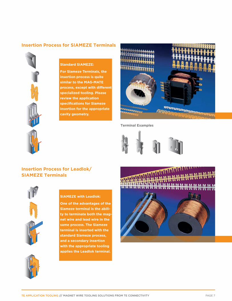
Insertion Process for SIAMEZE Terminals
Terminal Examples
Insertion Process for Leadlok/ SIAMEZE Terminals
Standard SIAMEZE:
For Siameze Terminals, the insertion process is quite similar to the MAG-MATE process, except with different specialized tooling. Please review the application specifications for Siameze insertion for the appropriate cavity geometry.
SIAMEZE with Leadlok:
One of the advantages of the Siameze terminal is the abili-ty to terminate both the mag-net wire and lead wire in the same process. The Siameze terminal is inserted with the standard Siameze process, and a secondary insertion with the appropriate tooling applies the Leadlok terminal.

TE APPLICATION TOOLING /// MAGNET WIRE TOOLING SOLUTIONS FROM TE CONNECTIVITY PAGE 8
APPLICATION TOOLING FOR MAGNET WIRE PROCESSING
Combination with manually operated tools
MAG-MATE insertion combined with crimping After MAG-MATE terminal insertion is done, the magnet
wire coil has to be connected to the outside world:
An example is the poke-in of a bare wire end or a
crimped terminal into the MAG-MATE Terminal:
Poke-in of a stripped solid wire end
For these terminals you need a crimp tool, e.g. a
CERTI-LOK hand tool or an SDE hand tool or a
PROCRIMPER hand tool.
Poke-in of crimped terminal For these terminals you need a crimp tool, e.g. a
CERTI-LOK hand tool or an SDE hand tool or a
PROCRIMPER hand tool.
MAG-MATE terminal Directly crimped
Inserted Terminals also can be crimped directly onto
a stranded wire.
Example: Mini MAG-MATE terminal with crimp con-
nection.
Crimp Terminal Examples

PAGE 9TE APPLICATION TOOLING /// MAGNET WIRE TOOLING SOLUTIONS FROM TE CONNECTIVITY
Manually operated tools for repair and serviceFor repair & service , but also for prototyping it can be
useful to work with manually operated tools.
Here you find some examples. For further manually
operated tools don’t hesitate to contact our specialists.
Manual MAG-MATE Terminal Application Manual SIAMEZE Leadlok Terminal Application

TE APPLICATION TOOLING /// MAGNET WIRE TOOLING SOLUTIONS FROM TE CONNECTIVITY PAGE 10
APPLICATION TOOLING FOR MAGNET WIRE PROCESSING
Work Center for semi automatic inserti-on of MAG-MATE or SIAMEZE terminalsWe offer standardized or customized work centers,
which are in line with the EU Machinery Directive
2006/42/EG. They are desiged to automatically insert
the terminals into the cavities of coil bodies. Correct
positioning of the coil in front of the inserter is done
either manually or automatically.
The work center consists of our inserter for MAGMATE
and SIAMEZE contacts being integrated into a
complete work environment.
After the coil is positioned,the terminals supplied on
reels are cut off from the carrier strip and inserted into
the contact chambers.
At this time the excess magnet wire is cut off and the
other side terminated in the terminal cavity using
insulation displacement technique.
Light grids assure protection of the worker during
operation of the machine.
Easy operation of the work place is possible by a touch
screen.
Insertion process is started by pedal switchnection.
Manual positioning of coil by use of a manually operated locator unit
Locator for manual positioning
Locator for automatical positioning Semi automatic positioning of coil by use of a motordriven locator unit

PAGE 11TE APPLICATION TOOLING /// MAGNET WIRE TOOLING SOLUTIONS FROM TE CONNECTIVITY
Workstation Application: MAG-MATE terminal with Multispring contact
Case: An electrical drive stator has to be combined with a
PCB. The cavities of the stators are designed for
MAG-MATE terminals. The thru holes of the PCB can be
contacted by Multispring.
Needed: A combination of MAG-MATE IDC and
press-fit contacting method.
Solution:
MAG-MATE terminal with Multispring contact.
After insertion of the terminals the PCB is pressed onto
the housing by means of a connector seating device.
Automatical WorkstationFor rough work environment we also can offer robust
designs for work places according to the specific needs
of our customers.
Components and Controls (Examples)
• Inserter Machine
• Electrical Power Supply Unit
• Compressed Air Supply Unit
• Touch Screen
• Emergency Stop Button
• Light Grid
• Malfunction Light
• Safeguard
• On Button/Off Button
Please contact our specialists for full specification of
the work center
Benchtop Custom SolutionsCustomized fixtures can be designed for specific
applications. processing two different terminals in the
same machine provides our customers with the most
economical solution, reducing processing and handling
times.

TE APPLICATION TOOLING /// MAGNET WIRE TOOLING SOLUTIONS FROM TE CONNECTIVITY PAGE 12
APPLICATION TOOLING FOR MAGNET WIRE PROCESSING
Splicing EquipmentAMP 5/K-40 CE thru splice terminator stand-alone semiautomatic bench machine for end feed and for side feed AMPLIVAR terminals.
Technical Data:
• Deflection: 0.13 mm [.0046 in.]
Maximum per 4,448 Newtons [1,000 lb] Crimp Force
• Noise: Less than 82 dBa Typical at operator position
with standard mechanical feed applicator
• Weight: 77.3 Kilograms [170.4 lb] — Height: 585 mm
[23 in.] without reel supports
• Electrical: 100 – 240 Vac, 50/60 Hz,
Single-Phase Current. Operating current is 3 amp
• Air: 620 – 760 kPa [90 – 100 psi], 2.83 liters/sec
(6 scfm) When required for use with air feed
applicators
• Physical Environment: Temperature:
4.45 – 40° C [40.5 – 104° F]
• Relative Humidity: Less than 95 % (non-condensing)
End-Feed and Side-Feed applicators used with
AMP 5/K-40 CE through-splice terminators are two-
piece applicators consisting of a tool holder and
applicator base.
The tool holder is secured to the ram of the
AMP 5/K-40 CE through-splice. All AMP 5/K-40 CE
through-splice terminators are equipped with
a “precision adjust” feature.
Splicing EquipmentThe wire ends being spliced together have to be
inserted into a slot in the protection guard.
A sight window allows correct positioning of the wire
ends over the open crimp terminal barrel.
The AMPLIVAR crimp terminals are either side feed or
end feed terminals. Accordingly a side feed or end feed
applicator has to be installed into the thru splice
terminator.
Side feed applicator with protection guard
AMPLIVAR Side feed terminal
AMPLIVAR End feed terminal
End feed applicator with protection guard
Additional hand protection guard

PAGE 13TE APPLICATION TOOLING /// MAGNET WIRE TOOLING SOLUTIONS FROM TE CONNECTIVITY
Splicing Equipment Pigtail Splices
AMPLIVAR product terminator (APT)
For pigtail-type splices (up to 3 wires in 1 splice) and
direct connect contacts
Technical Data:
• Weight: approx. 68 kg with CQM
• Width: 965 mm with CQM and
• Product Reel
• Depth: 890 mm
• Height: 356 mm
• Electrical: 240 VAC, 50 Hz, .5 A, 1 f
• Air: 5,5-7,5 bar
• Crimp Height Adjust in .0005 “ [0.013 mm]
increments over .064” range
For operations with multiple wire sizes, the APT 5A
provides programmable sequencing of different
crimp-height settings, and it can store up to 2,000
different programs of 7 different settings each.
The maximum time to auto-adjust between program-
med crimp heights is 2 seconds.
Splicing Equipment Pigtail SplicesTermination process:
• Magnet wire and lead wire are placed in the terminal
barrel being in the crimping position
• Operator depresses the foot switch
• Terminator automatically
– shears terminal from its strip
– crimps the terminal onto the wire
– shears off the excess wire
– advances the next terminal into the crimping
position
Remarks:
• Two or three wires may be joined in one splices
• Terminator designed for combinations of magnet
wire and lead wire (stranded, soldi or fused stranded)
• Large number of wire combinations requires some
tooling changes
• For the correct tooling selection, please contact our
specialists
• If customer CMA is less than the minimum published
CMA for the AMPLIVAR product, we offer our wire
stuffer assembly 2161635-1 as an option.
This option provides additional magnet wire CMA to
the terminated CMA to meet the specified CMA range
for a given AMPLIVAR product.

TE APPLICATION TOOLING /// MAGNET WIRE TOOLING SOLUTIONS FROM TE CONNECTIVITY PAGE 14
TE CONNECTIVITY APPLICATION TOOLING: IDC MACHINE QUOTATION QUESTIONNAIRE
Contact Information:
Please provide the following information so we can create an accurate quote for your production needs.
Product Information:
Specifications and Testing:
Attachments:
Company Name:Contact Name:
Company Address:
Contact Phone:Contact Email:
Please list all terminals to be inserted in this application:What products are you interested in?
If a fixture is requested, what level of automation is needed? Manual Semi-Automatic
Automated Line Integration
Will the machine be robotically loaded?Yes No
If the machine is integrated into a line, is host control required? Yes No
Will the machine be replacing an exisiting AMP or TE Connectivity machine? Yes No
What is your expected yearly terminal usage?
What timeframe do you expect for the start of production?
Do you have any machine specifications or requirements? Yes No
If you answered “Yes” to any of the questions regarding specifications and testing, please attach all appropriate documentation.
Do you have any testing/acceptance requirements?Yes No
In order to produce a complete quote, all of the following items must be attached. If not all documentation is currently available, a budgetary quote can be provided.
-Detailed, fully dimensioned and tolereanced drawings of bare bobbin/stator including material (e.g. 15% GF nylon)-Drawings of Completed Assembly [Including: TE terminal(s) part number(s), terminal orientation in cavity, magnet wire type (e.g. AL, CU), magnet wire gage, wrap-off trim (required or not re-quired)]-3D Models of the bobbin/stator assembly (CREO or .STP format) if available-All information on the wire that will be used for this application including, but not limited to: gage, number of strands, material, insulation type.
*Are you able to provide 5-10 samples of product for initial review? Yes No
**Do you require a run off of the machine?Yes No
Complete bench machine and fixture Module only
If you are replacing an existing machine, what is the machine part number?
Has your application been reviewed by a TE Connectivity Terminal Application Specialist? Yes NoIf so, who did you work with?
Please Note: *Customers are required to provide terminals adn bobbins/stators for all machine conditioning and qualification. **Additional charges may apply.
Please submit this form to:[email protected]
orTE ConnectivityP.O. Box 3605
Harrisburg, PA 17015M.S. 161-20
Attn: Magnet Wire
For best results, please review “Best Practices for IDC Magnet Wire Termination,” which can be found with other useful information at www.tooling.te.com

PAGE 15TE APPLICATION TOOLING /// MAGNET WIRE TOOLING SOLUTIONS FROM TE CONNECTIVITY
APPENDIX A: Overview on our full MAG-MATE MODULE portfolio
No OptionsMAG-MATE pneumatic
MPT-5MAG-MATE
MK IMAG-MATE
MK II
1 Moving Table X X X
2 Moving Tube X
3 Adapter Plate X X X
4 Suction system for waste disposal X X X X
5 Insertion force limitation, mechanical X X
6 Insertion force monitoring X
7 Separate wire cutting unit X X
8 Bridge function, 2 contacts X X X X
9 Bridge function, 3 contacts X X X
10 Bridge function, 4 contacts X X
11 Touch screen X X
12 Bridge On/Off function X X X
13 Processing function for Multispring X X
14 Fine adjust insertion depth X X
15 Language module for user interface X X
16 Electrical interface for base machine X X X

TE APPLICATION TOOLING /// MAGNET WIRE TOOLING SOLUTIONS FROM TE CONNECTIVITY
Let’s ConnectTo learn more about the right TE tooling for your needs, call us a 717-810-2082 or email [email protected]
TE Technical Support CenterUSA: 1.800.522.6752Canada: 1.800.522.6752Mexico: +52.55.11.06.0800 Latin/S. America +54.11.4733.2200Germany: +49.6151.607.1999
Waste Not. Want Not.
Whether its time or scrap, in manufacturing everyone knows that waste costs money. With our on-site certification and consultation services, we can help you:
• Reduce downtime• Reduce scrap• Maintain crimp quality• Improve manufacturing efficiency
Connect with us today to learn more.
• E-mail: [email protected]• Phone: 800-722-1111 or 717-986-3434• For additional information download catalog
#1-1307619-0 from www.tooling.te.com.
UK: +44.0800.267666 France: +33.1.34.20.8686Netherlands: +31.73.624.6999China: +86.400.820.6015
Catalog 1-1773899-1/ 4-17 / Application Tooling
TE connectivity (logo) and TE Connectivity are trademarks.
Time is Money.
In manufacturing downtime can be expensive. That’s why TE is constantly working to improve product availability and delivery
rates. With a strong global footprint, short lead times and a strong distribution channel, TE has the equipment and the accessories to keep production online.
To check distributor stock and availability for your tooling needs go to: www.te.com/commerce/sck/cdi.do