pdf04-analogue instruments
TRANSCRIPT
Analogue Measuring Instruments
Analogue instruments register a value to be measured and show it on ananalogue display, usually by a pointer on a scale. So the value is display-ed in a stepless and continuous way. In opposition to digital displays, insta-bilities and tendencies of a value can be recognized faster and more intui-tively on an analogue display. On the other hand at analogue displaysexact numerical values are more difficult to read compared to a digitalinstrument (reading error).
04Technical Features page 4/1
Alternating Current instruments (AC) page 4/5
Moving iron instruments page 4/5
Moving coil instruments with rectifier page 4/9
Volt- / Ammeter with switch page 4/13
Maximun demand indicators page 4/15
Triple- / quadruple instruments page 4/17
Power / Power factor meter page 4/21
Phase sequence indicators page 4/28
Frequency instruments page 4/29
Synchronization instruments page 4/31
Direct Current instruments (DC) page 4/35
Moving coil instruments page 4/35
Contact instruments page 4/39
Other types on demand
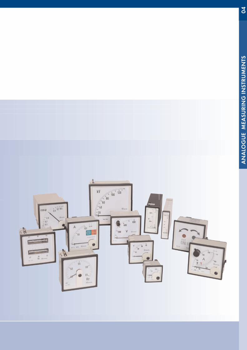
Analogue instruments are on hand for a broad band of electrical values.They are available in the standardized dimensions 48x48mm, 72x72mm,96x96mm and 144x144mm, as well as in various rectangle executions.
2
ANALOGUE MEASURING INSTRUMENTS
2<#>
04ANALO
GUE M
EASU
RIN
G IN
STRU
MEN
TS
4/1
SQUARE PLASTIC TYPE LINES
Meter typeRange
Test voltageUeff; 50 Hz Test voltage class
48n (300 / 600 V) 3,32 / 2,21 k V CAT III / CAT II
72n-, 96n-, 144n (300/ 600V) 3,32 / 2,21 k V CAT III / CAT II
Electrical Features
Overload according to IEC 60051 and EN 60051Moving iron instruments (EQ..n):
1,2 x In: continuouslyVoltmeter: 2 x Un (max. 1000 V): 5 secondsAmmeter 48: 10 x In: (max. 200 A) 5 secondsAmmeter others: 10 x In: 5 second
Bi-metallic instruments (BIQ..n/BOQ..n):1,2 x In: continuously10 x In: 1 second
Frequency instruments (FA..n/FAG..n):1,2 x Un: continuously
2 x Un: 1 secondMoving-coil instruments (PQ..n):
1,2 x In: continuouslyVoltmeter: 2 x Un: 5 secondsAmmeter: 10 x In: 5 seconds
Testing voltage according to IEC 61010-1 and EN 61010-1
Pointers and scales according to DIN 43802Moving iron panel instruments (EQ..n):90° scale. From 10 % of the scale practically linear. Coarse-fine division.
Pointer according to DIN 43802-3. In case of aminstruments with doubledoverload range the overload range corresponds to approximately 20 % ofthe full scale length.
Bimetallic-instruments (BIQ..n/BOQ..n):Bi-metallic meter movements: 90°scale. The final scale value is 1.2 x I metermovements: see moving iron panel instrumentsCoarse-fine division. Knife bar pointer according to DIN 43802-3.
Frequency instruments (FA..n, FAG..n):90°scales (FA..n), 240°scales (FAG..n). Practically linear. Coarse-fine divi-sion. Knife bar pointer according to DIN 43802-3.
Moving-coil measuring instruments (PQ..n, PAQ..n):90°scales (PQ..n), 240°scales (PAQ..n). Practically linear. Coarse-finedivision. Knife bar pointer according to DIN 43802-3.
ScalesThe final scale values are determined according to the following normline: 1-1,2-1,5-2-2,5-3-4-5-6-7,5-8 and decade multiples.In case of instruments for current transformer connection this norm line isadditionally supplemented with the standard values 1,25-1,6-1,8 anddecade multiples.
Special adjustment according to norm line in any measuring size, as forexample „%“, „m/s“, „Upm“, „bar“ etc.Special adjustment beyond the norm line, measuring size in any order.Special adjustment after equation, curve or table, measuring size in anyorder.
Technical Features
Ambient temperature: -10 ... +55 °CStorage temperature: -25 ... 65 °CReference temperature: +23° CRelative humidity: 75 % annual average, non-condensingClimate Class 2: according to VDE/VDI 3540External Magnetic field: 0.5 mT
0.4 kA/m lesser than 6% of the refe-rence value for EQ..n/EQD..n
Accuracy class according to IEC- 60051 and EN- 60051:Moving iron panel instruments (EQ..n)Class 1.5Frequency range Voltmeter: 15 ... 100 HzFrequency range Ammeter: 15 ... 400 Hz
Bi-metallic instruments (BIQ..n / BOQ..n):Class 3 for bi-metallic meter movements and class 1.5 for moving iron panelinstruments.
Pointer type frequency instruments (FA..n / FAG..n):Class 0.5Input voltage +/- 20 %Heating period lesser than 5 minutes
Moving-coil measuring instrument (PQ..n):Class 1.5 except for 15, 25, 40 and 60 µA class 2.5
Constructive FeaturesFor vertical front panel mounting: +/- 5 %
+/- 10 % in EQ/EQD/PR/PQ/PAQ..n
Housing according to DIN IEC 61554:Housing consists of self-extinguishing plastic according to UL 94-VO .
Fixing48n- instruments: 2x grip screw72n- and 96n-instruments: 2x snap closure (plastic clamp)144n- instruments: 4x grip screw
Front frame according to DIN 43718:Narrow frame colour black, similar to RAL 9005.
Front panelThe instruments are standard delivered with simple glass. The instrumentscan be delivered, if possible, with anti reflexing glass on request.
Degree of protectionIP 52 for EQ/PQ/PAQ/PAR/FA housing frontIP 40 for BIQ/BOQ housing frontIP 00 for clamps without electric shock protectionIP 10 for clamps with fixing electric shock protection
(except for 48 and EQ/PQ aminstruments higher than 6A)IP 20 for clamps with electric shock protection
Shaking resistance and mechanical shock resistanceShaking resistance: 1.5 g at 50 Hz
(10-150-10 Hz / 0,15 mm)Shock resistance: 15 g 11 ms(Gravitational acceleration 1 g = 9,81 m/s2)This can be obtained by sprung bearing jewels of the highest quality(which are saved against crushes of jewel storage).
4/2
ANALO
GUE M
EASU
RIN
G IN
STRU
MEN
TS
SQUARE PLASTIC TYPE LINES 04Test voltage
of the measuring range
Test voltageUeff; 50 Hz Test voltage sign
660 V 2000 V
1000 V 3000 V
General Purpose
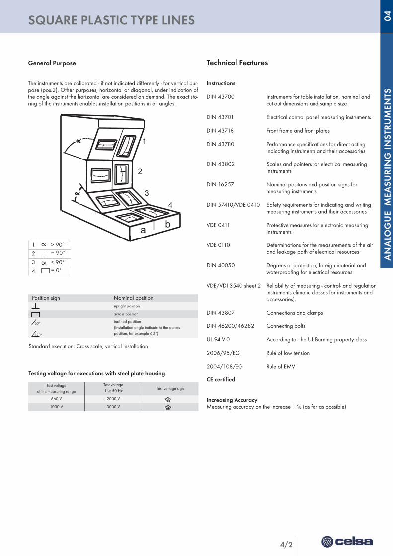
The instruments are calibrated - if not indicated differently - for vertical pur-pose (pos.2). Other purposes, horizontal or diagonal, under indication ofthe angle against the horizontal are considered on demand. The exact sto-ring of the instruments enables installation positions in all angles.
1
2
34
a b
1 > 90º
2 = 90º
3 < 90º
4 = 0º
Position sign Nominal positionupright position
across position
inclined position(Installation angle indicate to the acrossposition, for example 60°)
Technical Features
Instructions
DIN 43700 Instruments for table installation, nominal and cut-out dimensions and sample size
DIN 43701 Electrical control panel measuring instruments
DIN 43718 Front frame and front plates
DIN 43780 Performance specifications for direct acting indicating instruments and their accessories
DIN 43802 Scales and pointers for electrical measuring instruments
DIN 16257 Nominal positons and position signs for measuring instruments
DIN 57410/VDE 0410 Safety requirements for indicating and writing measuring instruments and their accessories
VDE 0411 Protective measures for electronic measuring instruments
VDE 0110 Determinations for the measurements of the air and leakage path of electrical resources
DIN 40050 Degrees of protection; foreign material and waterproofing for electrical resources
VDE/VDI 3540 sheet 2 Reliability of measuring - control- and regulationinstruments climatic classes for instruments and accessories).
DIN 43807 Connections and clamps
DIN 46200/46282 Connecting bolts
UL 94 V-0 According to the UL Burning property class
2006/95/EG Rule of low tension
2004/108/EG Rule of EMV
CE certified
Increasing AccuracyMeasuring accuracy on the increase 1 % (as far as possible)
60°
120°
Standard execution: Cross scale, vertical installation
Testing voltage for executions with steel plate housing
4/3
RECTANGULAR TYPE LINE
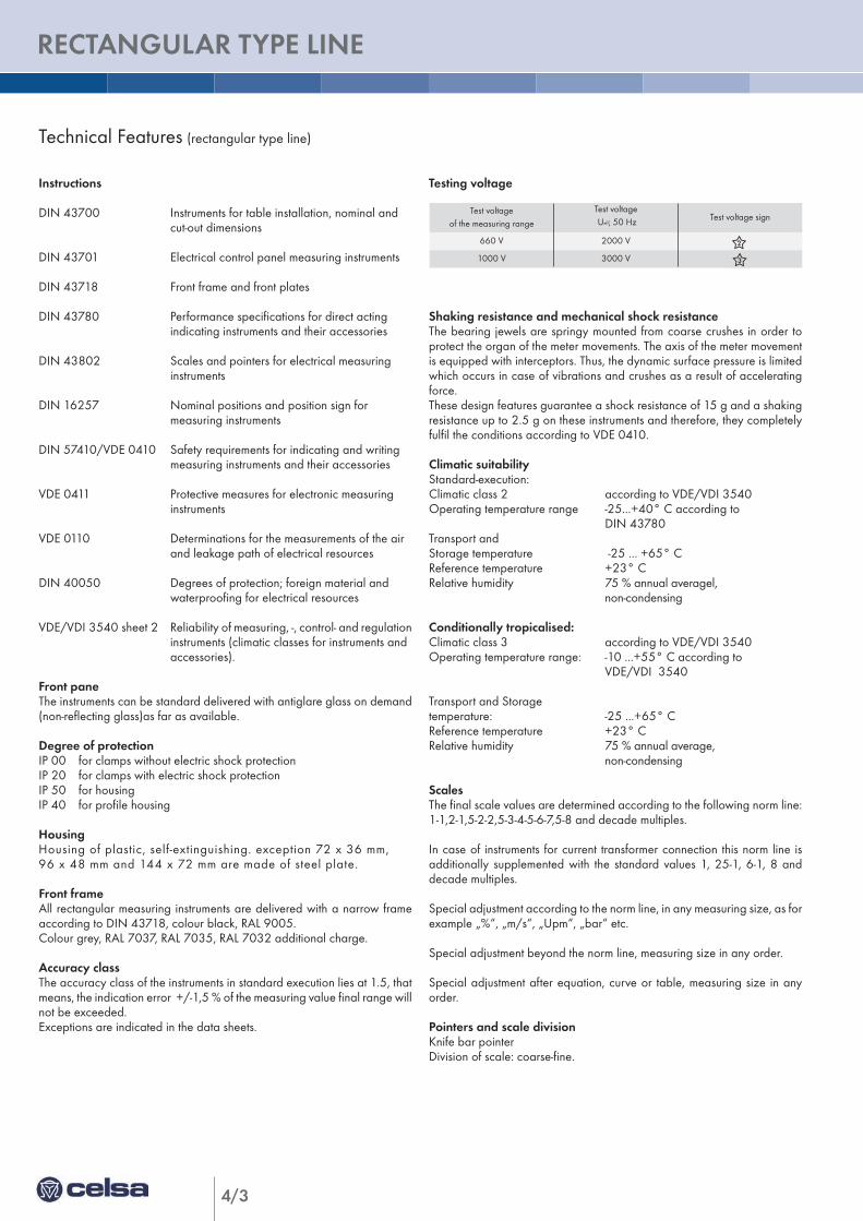
Test voltageof the measuring range
Test voltageUeff; 50 Hz Test voltage sign
660 V 2000 V
1000 V 3000 V
Testing voltage
Shaking resistance and mechanical shock resistanceThe bearing jewels are springy mounted from coarse crushes in order toprotect the organ of the meter movements. The axis of the meter movementis equipped with interceptors. Thus, the dynamic surface pressure is limitedwhich occurs in case of vibrations and crushes as a result of acceleratingforce. These design features guarantee a shock resistance of 15 g and a shakingresistance up to 2.5 g on these instruments and therefore, they completelyfulfil the conditions according to VDE 0410.
Climatic suitabilityStandard-execution:Climatic class 2 according to VDE/VDI 3540Operating temperature range -25...+40° C according to
DIN 43780Transport andStorage temperature -25 ... +65° CReference temperature +23° CRelative humidity 75 % annual averagel,
non-condensing
Conditionally tropicalised:Climatic class 3 according to VDE/VDI 3540Operating temperature range: -10 ...+55° C according to
VDE/VDI 3540
Transport and Storagetemperature: -25 ...+65° CReference temperature +23° CRelative humidity 75 % annual average,
non-condensing
ScalesThe final scale values are determined according to the following norm line:1-1,2-1,5-2-2,5-3-4-5-6-7,5-8 and decade multiples.
In case of instruments for current transformer connection this norm line isadditionally supplemented with the standard values 1, 25-1, 6-1, 8 anddecade multiples.
Special adjustment according to the norm line, in any measuring size, as forexample „%“, „m/s“, „Upm“, „bar“ etc.
Special adjustment beyond the norm line, measuring size in any order.
Special adjustment after equation, curve or table, measuring size in anyorder.
Pointers and scale divisionKnife bar pointerDivision of scale: coarse-fine.
Technical Features (rectangular type line)
Instructions
DIN 43700 Instruments for table installation, nominal and cut-out dimensions
DIN 43701 Electrical control panel measuring instruments
DIN 43718 Front frame and front plates
DIN 43780 Performance specifications for direct acting indicating instruments and their accessories
DIN 43802 Scales and pointers for electrical measuring instruments
DIN 16257 Nominal positions and position sign for measuring instruments
DIN 57410/VDE 0410 Safety requirements for indicating and writing measuring instruments and their accessories
VDE 0411 Protective measures for electronic measuring instruments
VDE 0110 Determinations for the measurements of the air and leakage path of electrical resources
DIN 40050 Degrees of protection; foreign material and waterproofing for electrical resources
VDE/VDI 3540 sheet 2 Reliability of measuring, -, control- and regulationinstruments (climatic classes for instruments and accessories).
Front paneThe instruments can be standard delivered with antiglare glass on demand(non-reflecting glass)as far as available.
Degree of protectionIP 00 for clamps without electric shock protectionIP 20 for clamps with electric shock protectionIP 50 for housingIP 40 for profile housing
HousingHousing of plastic, self-extinguishing. exception 72 x 36 mm, 96 x 48 mm and 144 x 72 mm are made of steel plate.
Front frameAll rectangular measuring instruments are delivered with a narrow frameaccording to DIN 43718, colour black, RAL 9005. Colour grey, RAL 7037, RAL 7035, RAL 7032 additional charge.
Accuracy classThe accuracy class of the instruments in standard execution lies at 1.5, thatmeans, the indication error +/-1,5 % of the measuring value final range willnot be exceeded.Exceptions are indicated in the data sheets.
4/4
ANALO
GUE M
EASU
RIN
G IN
STRU
MEN
TS
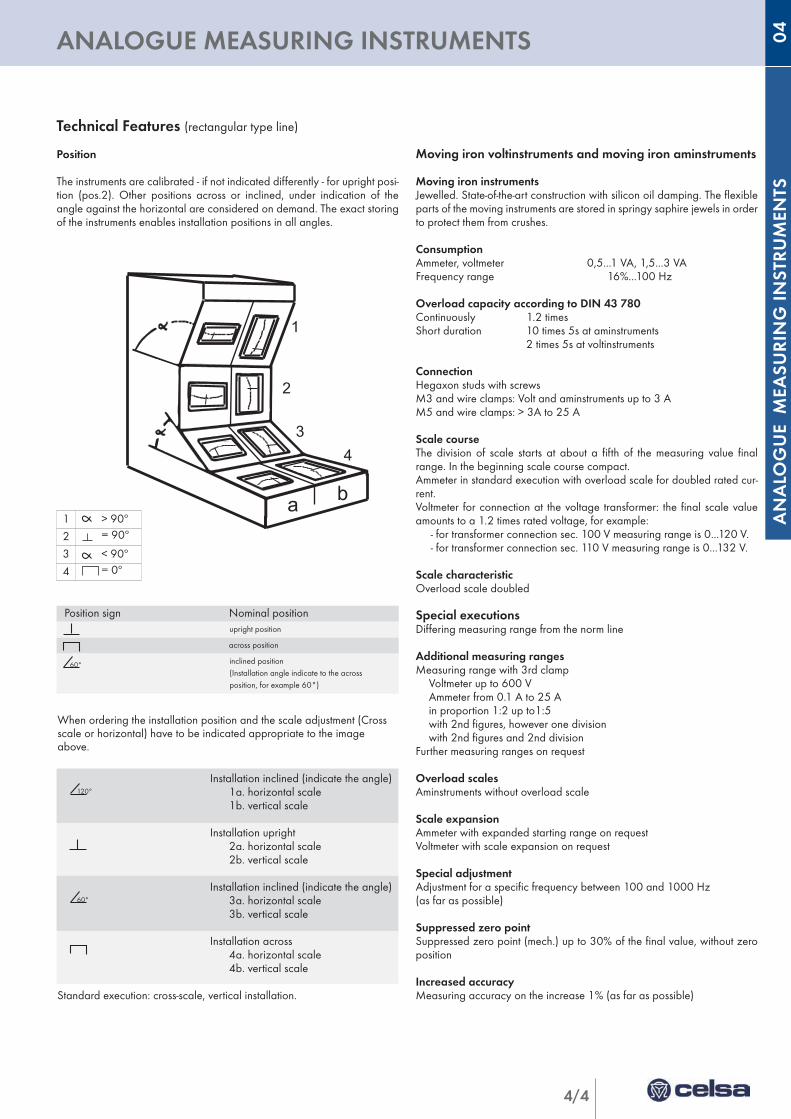
ANALOGUE MEASURING INSTRUMENTS 04Installation inclined (indicate the angle)
1a. horizontal scale1b. vertical scale
Installation upright2a. horizontal scale2b. vertical scale
Installation inclined (indicate the angle)3a. horizontal scale3b. vertical scale
Installation across4a. horizontal scale4b. vertical scale
Position sign Nominal positionupright position
across position
inclined position(Installation angle indicate to the acrossposition, for example 60°)
Technical Features (rectangular type line)
Position
The instruments are calibrated - if not indicated differently - for upright posi-tion (pos.2). Other positions across or inclined, under indication of theangle against the horizontal are considered on demand. The exact storingof the instruments enables installation positions in all angles.
Moving iron voltinstruments and moving iron aminstruments
Moving iron instrumentsJewelled. State-of-the-art construction with silicon oil damping. The flexibleparts of the moving instruments are stored in springy saphire jewels in orderto protect them from crushes.
ConsumptionAmmeter, voltmeter 0,5...1 VA, 1,5...3 VAFrequency range 16%...100 Hz
Overload capacity according to DIN 43 780Continuously 1.2 timesShort duration 10 times 5s at aminstruments
2 times 5s at voltinstruments
ConnectionHegaxon studs with screws M3 and wire clamps: Volt and aminstruments up to 3 AM5 and wire clamps: > 3A to 25 A
Scale courseThe division of scale starts at about a fifth of the measuring value finalrange. In the beginning scale course compact.Ammeter in standard execution with overload scale for doubled rated cur-rent.Voltmeter for connection at the voltage transformer: the final scale valueamounts to a 1.2 times rated voltage, for example:
- for transformer connection sec. 100 V measuring range is 0...120 V.- for transformer connection sec. 110 V measuring range is 0...132 V.
Scale characteristicOverload scale doubled
Special executionsDiffering measuring range from the norm line
Additional measuring rangesMeasuring range with 3rd clamp
Voltmeter up to 600 VAmmeter from 0.1 A to 25 Ain proportion 1:2 up to1:5with 2nd figures, however one divisionwith 2nd figures and 2nd division
Further measuring ranges on request
Overload scalesAminstruments without overload scale
Scale expansionAmmeter with expanded starting range on requestVoltmeter with scale expansion on request
Special adjustmentAdjustment for a specific frequency between 100 and 1000 Hz (as far as possible)
Suppressed zero pointSuppressed zero point (mech.) up to 30% of the final value, without zeroposition
Increased accuracyMeasuring accuracy on the increase 1% (as far as possible)
60°
120°
1
2
34
a b
60°
1 > 90º
2 = 90º
3 < 90º
4 = 0º
Standard execution: cross-scale, vertical installation.
When ordering the installation position and the scale adjustment (Crossscale or horizontal) have to be indicated appropriate to the imageabove.
4/5
MOVING IRON PANEL INSTRUMENTS
Description
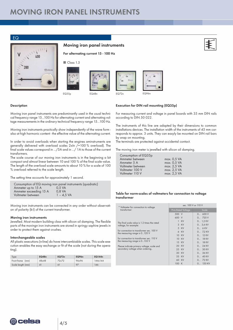
Moving iron panel instruments are predominantly used in the usual techni-cal frequency range 15...100 Hz for alternating current and alternating vol-tage measurements in the ordinary technical frequency range 15...100 Hz.
Moving iron instruments practically show independently of the wave form -also at high harmonic content - the effective value of the alternating current.
In order to avoid overloads when starting the engines aminstruments aregenerally delivered with overload scales 2xIn /=100 % overload). Thefinal scale values correspond in .../5A and in .../ 1A to those of the currenttransformers.The scale course of our moving iron instruments is in the beginning a bitcompact and almost linear between 10 and 100 % of the final scale value.The length of the overload scale amounts to about 10 % for a scale of 100% overload referred to the scale length.
The setting time accounts for approximately 1 second.
Moving iron instruments can be connected in any order without observati-on of polarity (k-I) of the current transformer.
Moving iron instrumentsJewelled. Most modern building class with silicon oil damping. The flexibleparts of the movingn iron instruments are stored in springy saphire jewels inorder to protect them against crushes.
Interchangeable scales All plastic executions (n-line) do have intercambiable scales. This scale exe-cution enables the easy exchange or fit of the scale (not during the opera-ting).
Consumption of EQ moving iron panel instruments (quadratic)Ammeter up to 15 A 0,5 VAAmmeter exceeding 15 A 0,8 VAVoltmeter between 1 – 4,5 VA
Execution for DIN rail mounting (EQ35p)
For measuring current and voltage in panel boards with 35 mm DIN railsaccording to DIN 50 022.
The instruments of this line are adapted by their dimensions to commoninstallations devices. The installation width of the instruments of 45 mm cor-responds to approx. 3 units. They can easyly be mounted on DIN rail barsby snap on mounting.The terminals are protected against accidental contact.
The moving iron meter is jewelled with silicon oil damping.
Table for norm-scales of voltmeters for connection to voltage transformer
Moving iron panel instruments
For alternating current 15 - 100 Hz
n Class 1.5
EQ
EQ35p EQ48n EQ72n EQ96n
* Voltmeter for connection to voltagetransformer:
The final scale value is 1.2 times the rated voltage, for example:
for connection to transformer sec. 100 Vthe measuring range is 0...120 V
for connection to transformer sec. 110 Vthe measuring range is 0...132 V
Please indicate primary voltage, scale and secondary voltage when ordering..
sec. 100 V or 110 V
Prim.Rated Voltage Scale
500 V600 V
1 KV3 KV5 KV6 KV
10 KV10 KV15 KV20 KV25 KV30 KV33 KV60 KV
100 K
0... 600 V0... 720 V0... 1,2 KV0... 3,6 KV0... 6 KV0... 7,2 KV0... 12 KV0... 18 KV0... 18 KV0... 24 KV0... 30 KV0... 36 KV0... 40 KV0... 72 KV0... 120 KV
Consumption of EQ35pAmmeter between max. 0,5 VAAmmeter 5 A max. 0,5 VAVoltmeter between max. 2,5 VAVoltmeter 100 V max. 2,5 VAVoltmeter 110 V max. 2,5 VA
Type EQ48n EQ72n EQ96n EQ144n
Front frame (mm) 48x48 72x72 96x96 144x144
Scale length (mm) 41 61 97 146
4/6
ANALO
GUE M
EASU
RIN
G IN
STRU
MEN
TS
MOVING IRON PANEL INSTRUMENTS 04
vu
VU
N (L2)L1
0 (S)R
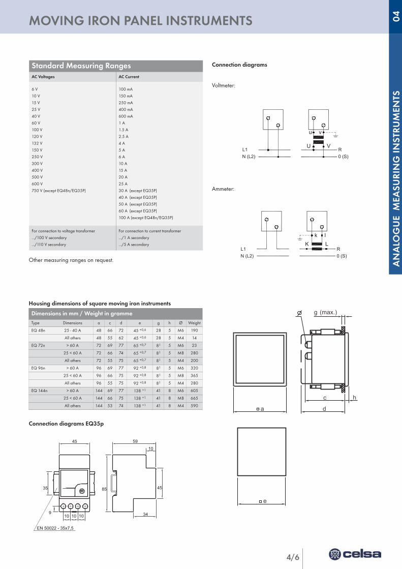
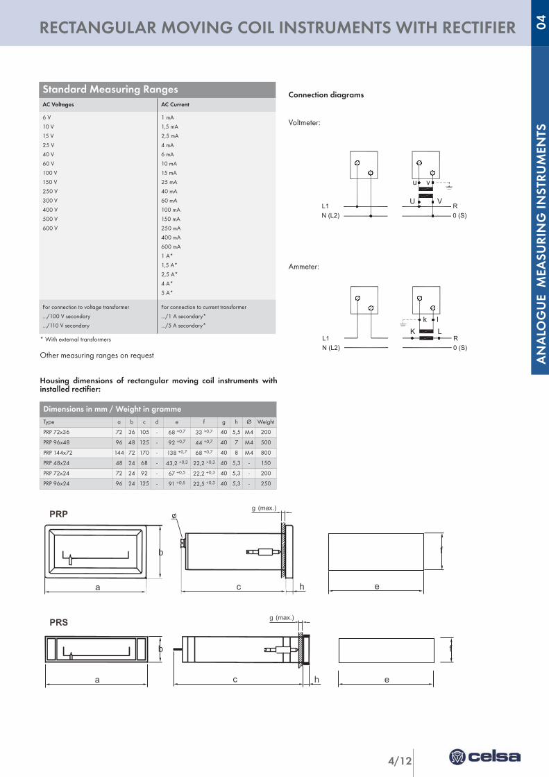
Connection diagrams
Voltmeter:
Ammeter:
Other measuring ranges on request.
Housing dimensions of square moving iron instruments
Connection diagrams EQ35p
Standard Measuring RangesAC Voltages AC Current
6 V
10 V
15 V
25 V
40 V
60 V
100 V
120 V
132 V
150 V
250 V
300 V
400 V
500 V
600 V
750 V (except EQ48n/EQ35P)
100 mA
150 mA
250 mA
400 mA
600 mA
1 A
1.5 A
2.5 A
4 A
5 A
6 A
10 A
15 A
20 A
25 A
30 A (except EQ35P)
40 A (except EQ35P)
50 A (except EQ35P)
60 A (except EQ35P)
100 A (except EQ48n/EQ35P)
For connection to voltage transformer
.../100 V secondary
.../110 V secondary
For connection to current transformer
.../1 A secondary
.../5 A secondary
Dimensions in mm / Weight in grammeType Dimensions a c d e g h Ø Weight
EQ 48n 25 - 40 A 48 66 72 45 +0,6 28 5 M6 190
All others 48 55 62 45 +0,6 28 5 M4 14
EQ 72n > 60 A 72 69 77 65 +0,7 81 5 M6 23
25 < 60 A 72 66 74 65 +0,7 81 5 M8 280
All others 72 55 75 65 +0,7 81 5 M4 200
EQ 96n > 60 A 96 69 77 92 +0,8 81 5 M6 320
25 < 60 A 96 66 75 92 +0,8 81 5 M8 365
All others 96 55 75 92 +0,8 81 5 M4 280
EQ 144n > 60 A 144 69 77 138 +1 41 8 M6 605
25 < 60 A 144 66 75 138 +1 41 8 M8 665
All others 144 53 74 138 +1 41 8 M4 590
K Lk l
R0 (S)N (L2)
L1
a d
c
g (max.)
h
e
10 10 109
35
45 59
10
34
4585
EN 50022 - 35x7,5
4/7
RECTANGULAR MOVING IRON PANEL INSTRUMENTS
Description
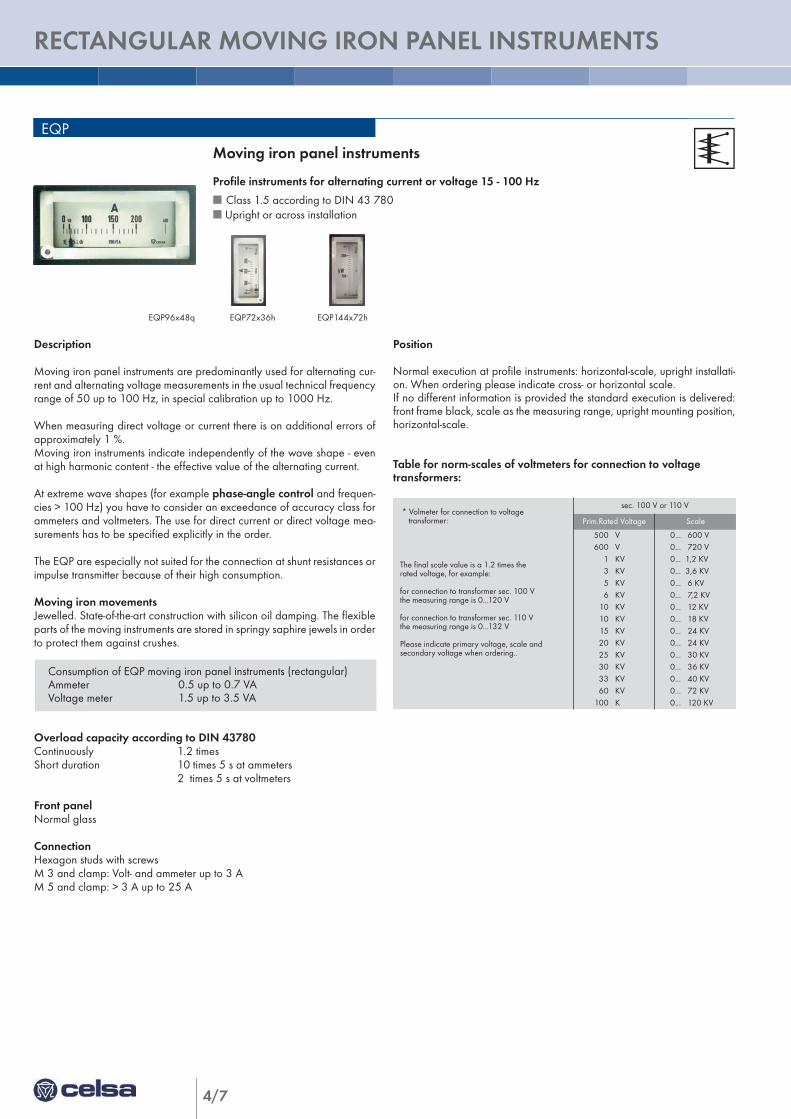
Moving iron panel instruments are predominantly used for alternating cur-rent and alternating voltage measurements in the usual technical frequencyrange of 50 up to 100 Hz, in special calibration up to 1000 Hz.
When measuring direct voltage or current there is on additional errors ofapproximately 1 %.Moving iron instruments indicate independently of the wave shape - evenat high harmonic content - the effective value of the alternating current.
At extreme wave shapes (for example phase-angle control and frequen-cies > 100 Hz) you have to consider an exceedance of accuracy class forammeters and voltmeters. The use for direct current or direct voltage mea-surements has to be specified explicitly in the order.
The EQP are especially not suited for the connection at shunt resistances orimpulse transmitter because of their high consumption.
Moving iron movementsJewelled. State-of-the-art construction with silicon oil damping. The flexibleparts of the moving instruments are stored in springy saphire jewels in orderto protect them against crushes.
Overload capacity according to DIN 43780Continuously 1.2 timesShort duration 10 times 5 s at ammeters
2 times 5 s at voltmeters
Front panelNormal glass
ConnectionHexagon studs with screwsM 3 and clamp: Volt- and ammeter up to 3 AM 5 and clamp: > 3 A up to 25 A
EQP
Position
Normal execution at profile instruments: horizontal-scale, upright installati-on. When ordering please indicate cross- or horizontal scale.If no different information is provided the standard execution is delivered:front frame black, scale as the measuring range, upright mounting position,horizontal-scale.
Table for norm-scales of voltmeters for connection to voltage transformers:
Moving iron panel instruments
Profile instruments for alternating current or voltage 15 - 100 Hz
n Class 1.5 according to DIN 43 780n Upright or across installation
* Volmeter for connection to voltagetransformer:
The final scale value is a 1.2 times therated voltage, for example:
for connection to transformer sec. 100 Vthe measuring range is 0...120 V
for connection to transformer sec. 110 Vthe measuring range is 0...132 V
Please indicate primary voltage, scale and secondary voltage when ordering..
sec. 100 V or 110 V
Prim.Rated Voltage Scale
500 V600 V
1 KV3 KV5 KV6 KV
10 KV10 KV15 KV20 KV25 KV30 KV33 KV60 KV
100 K
0... 600 V0... 720 V0... 1,2 KV0... 3,6 KV0... 6 KV0... 7,2 KV0... 12 KV0... 18 KV0... 24 KV0... 24 KV0... 30 KV0... 36 KV0... 40 KV0... 72 KV0... 120 KV
Consumption of EQP moving iron panel instruments (rectangular)Ammeter 0.5 up to 0.7 VAVoltage meter 1.5 up to 3.5 VA
EQP72x36h EQP144x72hEQP96x48q
vu
VU
N (L2)L1
0 (S)R
4/8
ANALO
GUE M
EASU
RIN
G IN
STRU
MEN
TS
RECTANGULAR MOVING IRON PANEL INSTRUMENTS 04
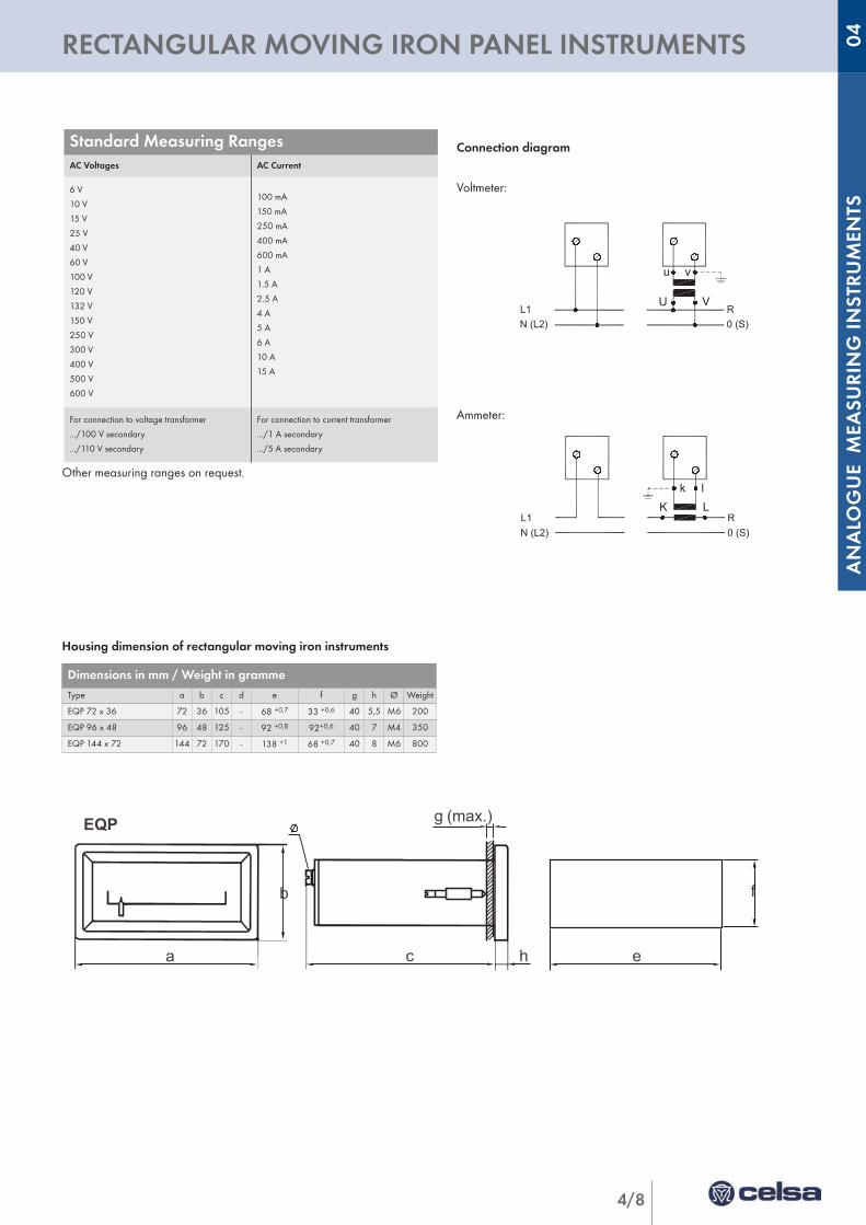
Standard Measuring RangesAC Voltages AC Current
6 V
10 V
15 V
25 V
40 V
60 V
100 V
120 V
132 V
150 V
250 V
300 V
400 V
500 V
600 V
100 mA
150 mA
250 mA
400 mA
600 mA
1 A
1.5 A
2.5 A
4 A
5 A
6 A
10 A
15 A
For connection to voltage transformer
.../100 V secondary
.../110 V secondary
For connection to current transformer
.../1 A secondary
.../5 A secondary
K Lk l
R0 (S)N (L2)
L1
b
ha c e
f
EQP (max.)g
Connection diagram
Voltmeter:
Ammeter:
Other measuring ranges on request.
Housing dimension of rectangular moving iron instruments
Dimensions in mm / Weight in grammeType a b c d e f g h Ø Weight
EQP 72 x 36 72 36 105 - 68 +0,7 33 +0,6 40 5,5 M6 200
EQP 96 x 48 96 48 125 - 92 +0,8 92+0,6 40 7 M4 350
EQP 144 x 72 144 72 170 - 138 +1 68 +0,7 40 8 M6 800
4/9
MOVING COIL INSTRUMENTS WITH RECTIFIER
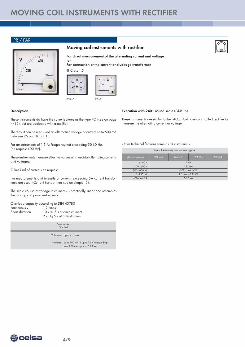
Description
These instruments do have the same features as the type PQ (see on page4/35), but are equipped with a rectifier.
Thereby, it can be measured an alternating voltage or current up to 600 mAbetween 25 and 1000 Hz.
For aminstruments of 1-5 A: Frequency not exceeding 50-60 Hz.(on request 400 Hz).
These instruments measure effective values at sinusoidal alternating currentsand voltages.
Other kind of currents on request.
For measurements and intensity of currents exceeding 5A current transfor-mers are used. (Current transformers see on chapter 5).
The scale course at voltage instruments is practically linear and resemblesthe moving coil panel instruments.
Overload capacity according to DIN 43780continuously 1.2 timesShort duration 10 x IN 5 s at aminstrument
2 x UN 5 s at aminstrument
Internal resistance, consumption approx.
Measuring range PAR 48n PAR 72n PAR 96n PAR 144n
6 - 60 V 1 mA
100 - 600 V 1.12 mA
200 - 600 µA 0.01 - 1.64 m VA
1 -250 mA 1.6 mVA - 0.76 VA
400 mA - 5 A 0.38 VA
PR / PAR
Execution with 240° round scale (PAR...n)
These instruments are similar to the PAQ...n but have an installed rectifier tomeasure the alternating current or voltage.
Other technical features same as PR instruments.
PR...nPAR...n
Moving coil instruments with rectifier
For direct measurement of the alternating current and voltageor For connection at the current and voltage transformer
n Class 1.5
ConsumptionPR / PAR
Voltmeter:
Ammeter:
approx.. 1 mA
up to 800 mA: 1 up to 1.5 V voltage dropfrom 800 mA: approx. 0.25 VA
vu
VU
N (L2)L1
0 (S)R
K Lk l
R0 (S)N (L2)
L1
4/10
ANALO
GUE M
EASU
RIN
G IN
STRU
MEN
TS
MOVING COIL INSTRUMENTS WITH RECTIFIER 04
a d
c
g (max.)
h
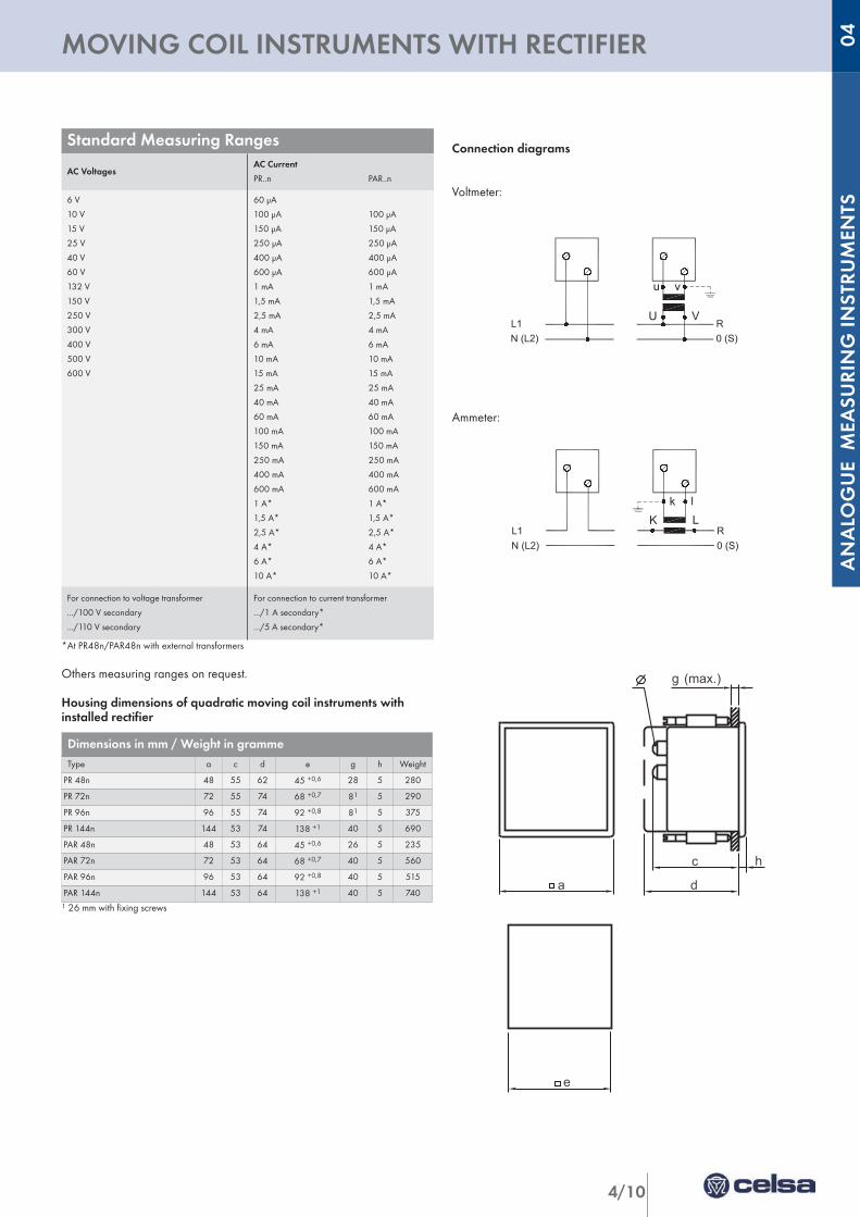
Connection diagrams
Voltmeter:
Ammeter:
*At PR48n/PAR48n with external transformers
Others measuring ranges on request.
Housing dimensions of quadratic moving coil instruments withinstalled rectifier
1 26 mm with fixing screws
Standard Measuring Ranges
AC VoltagesAC Current
PR..n PAR..n
6 V
10 V
15 V
25 V
40 V
60 V
132 V
150 V
250 V
300 V
400 V
500 V
600 V
60 µA
100 µA 100 µA
150 µA 150 µA
250 µA 250 µA
400 µA 400 µA
600 µA 600 µA
1 mA 1 mA
1,5 mA 1,5 mA
2,5 mA 2,5 mA
4 mA 4 mA
6 mA 6 mA
10 mA 10 mA
15 mA 15 mA
25 mA 25 mA
40 mA 40 mA
60 mA 60 mA
100 mA 100 mA
150 mA 150 mA
250 mA 250 mA
400 mA 400 mA
600 mA 600 mA
1 A* 1 A*
1,5 A* 1,5 A*
2,5 A* 2,5 A*
4 A* 4 A*
6 A* 6 A*
10 A* 10 A*
For connection to voltage transformer
.../100 V secondary
.../110 V secondary
For connection to current transformer
.../1 A secondary*
.../5 A secondary*
Dimensions in mm / Weight in grammeType a c d e g h Weight
PR 48n 48 55 62 45 +0,6 28 5 280
PR 72n 72 55 74 68 +0,7 81 5 290
PR 96n 96 55 74 92 +0,8 81 5 375
PR 144n 144 53 74 138 +1 40 5 690
PAR 48n 48 53 64 45 +0,6 26 5 235
PAR 72n 72 53 64 68 +0,7 40 5 560
PAR 96n 96 53 64 92 +0,8 40 5 515
PAR 144n 144 53 64 138 +1 40 5 740
e
4/11
RECTANGULAR MOVING COIL INSTRUMENTS WITH RECTIFIER
Internal resistance, consumption approx.
Measuring range PRP 72 x 36sPRS 48 x 24p
PRP 96 x 48sPRS 72 x 24p
PRP 144 x 72sPRS 96 x 24p
µA~ 10 - 600 - - -
mA~ 1 - 600 1.2 V 1.2 V 1.2 V
A~ 11,5 2,5
5
1.2 VA
0.3VA V~ 1.5 - 600 1000 Ω/V
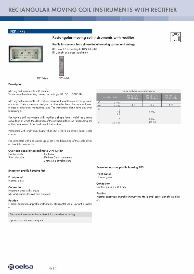
Description
Moving coil instruments with rectifier:To measure the alternating current and voltage 40…50…10000 Hz.
Moving coil instruments with rectifier measure the arithmetic average valueof current. Their scales are designed so that effective values are indicatedin case of sinusoidal measuring sizes. The instruments don’t have any over-load range.
For moving coil instruments with rectifier a shape form is valid as a ratedcurve form at which the deviation of the sinusoidal form isn’t exceeding 1%of the peak value of the fundamental vibration.
Voltmeters with end-values higher than 20 V, have an almost linear scalecourse.
For voltmeters with end-values up to 20 V the beginning of the scale divisi-on is a little compressed.
Overload capacity according to DIN 43780Continuously: 1.2 timesShort duration: 10 times 5 s at ammeters
2 times 5 s at voltmeters
Execution profile housing PRP:
Front panelNormal glass
ConnectionHegaxon studs with screwsM3 and clamps for volt and ammeter
PositionNormal execution at profile instruments: Horizontal scale, upright installati-on.
PRP / PRS
Rectangular moving coil instruments with rectifier
Profile instruments for a sinusoidal alternating current and voltage
n Class 1.5 according to DIN 43 780n Upright or across installation
Execution narrow profile housing PRS:
Front panelNormal glass
ConnectionContact pin 6,3 x 0,8 mm
PositionNormal execution at profile instruments: Horizontal scale, upright installati-on.
Please indicate vertical or horizontal scale when ordering.
Special executions on request
PRS96x24hPRP96x24q
vu
VU
N (L2)L1
0 (S)R
K Lk l
R0 (S)N (L2)
L1
4/12
ANALO
GUE M
EASU
RIN
G IN
STRU
MEN
TS
RECTANGULAR MOVING COIL INSTRUMENTS WITH RECTIFIER 04
e
f
a c h
b
PRS (max.)g
Connection diagrams
Voltmeter:
Ammeter:
b
ha c e
f
PRP(max.)g
* With external transformers
Other measuring ranges on request
Housing dimensions of rectangular moving coil instruments withinstalled rectifier:
Standard Measuring RangesAC Voltages AC Current
6 V
10 V
15 V
25 V
40 V
60 V
100 V
150 V
250 V
300 V
400 V
500 V
600 V
1 mA
1,5 mA
2,5 mA
4 mA
6 mA
10 mA
15 mA
25 mA
40 mA
60 mA
100 mA
150 mA
250 mA
400 mA
600 mA
1 A*
1,5 A*
2,5 A*
4 A*
5 A*
For connection to voltage transformer
.../100 V secondary
.../110 V secondary
For connection to current transformer
.../1 A secondary*
.../5 A secondary*
Dimensions in mm / Weight in grammeType a b c d e f g h Ø Weight
PRP 72x36 72 36 105 - 68 +0,7 33 +0,7 40 5,5 M4 200
PRP 96x48 96 48 125 - 92 +0,7 44 +0,7 40 7 M4 500
PRP 144x72 144 72 170 - 138 +0,7 68 +0,7 40 8 M4 800
PRP 48x24 48 24 68 - 43,2 +0,3 22,2 +0,3 40 5,3 - 150
PRP 72x24 72 24 92 - 67 +0,5 22,2 +0,3 40 5,3 - 200
PRP 96x24 96 24 125 - 91 +0,5 22,5 +0,3 40 5,3 - 250
4/13
SWITCHABLE MOVING IRON PANEL INSTRUMENTS
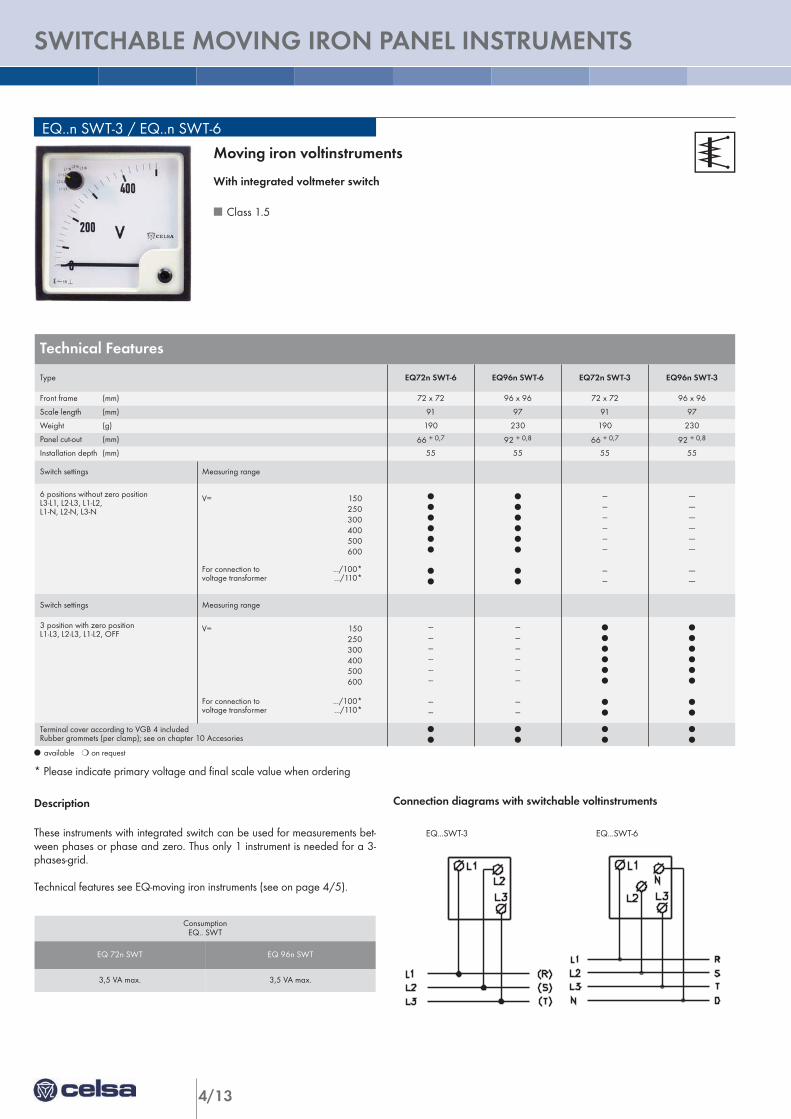
Connection diagrams with switchable voltinstruments
EQ...SWT-3 EQ...SWT-6
EQ..n SWT-3 / EQ..n SWT-6
l available m on request
* Please indicate primary voltage and final scale value when ordering
Description
These instruments with integrated switch can be used for measurements bet-ween phases or phase and zero. Thus only 1 instrument is needed for a 3-phases-grid.
Technical features see EQ-moving iron instruments (see on page 4/5).
Moving iron voltinstruments
With integrated voltmeter switch
n Class 1.5
ConsumptionEQ.. SWT
EQ 72n SWT EQ 96n SWT
3,5 VA max. 3,5 VA max.
Technical Features
Type EQ72n SWT-6 EQ96n SWT-6 EQ72n SWT-3 EQ96n SWT-3
Front frame (mm) 72 x 72 96 x 96 72 x 72 96 x 96
Scale length (mm) 91 97 91 97
Weight (g) 190 230 190 230
Panel cut-out (mm) 66 + 0,7 92 + 0,8 66 + 0,7 92 + 0,8
Installation depth (mm) 55 55 55 55
Switch settings Measuring range
6 positions without zero positionL3-L1, L2-L3, L1-L2, L1-N, L2-N, L3-N
V= 150250300400500600
For connection to .../100*voltage transformer .../110*
l
l
l
l
l
l
l
l
l
l
l
l
l
l
l
l
------------------
------
------------------------
--------
Switch settings Measuring range
3 position with zero positionL1-L3, L2-L3, L1-L2, OFF
V= 150250300400500600
For connection to .../100*voltage transformer .../110*
------------------
------
------------------
------
l
l
l
l
l
l
l
l
l
l
l
l
l
l
l
l
Terminal cover according to VGB 4 includedRubber grommets (per clamp); see on chapter 10 Accesories
l
l
l
l
l
l
l
l
4/14
ANALO
GUE M
EASU
RIN
G IN
STRU
MEN
TS
SWITCHABLE MOVING IRON PANEL INSTRUMENTS 04
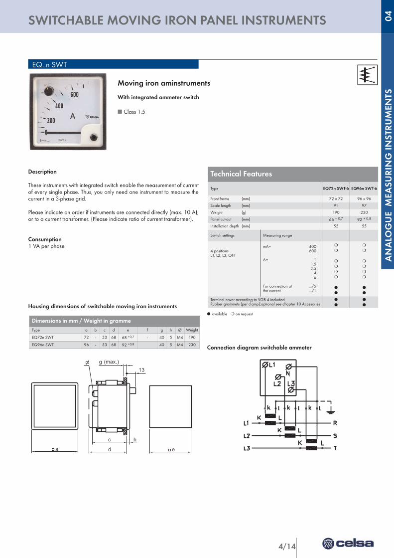
Description
These instruments with integrated switch enable the measurement of currentof every single phase. Thus, you only need one instrument to measure thecurrent in a 3-phase grid.
Please indicate on order if instruments are connected directly (max. 10 A),or to a current transformer. (Please indicate ratio of current transformer).
Consumption1 VA per phase
Housing dimensions of switchable moving iron instruments
Connection diagram switchable ammeter
EQ..n SWT
l available m on request
Moving iron aminstruments
With integrated ammeter switch
n Class 1.5
a
c
d
g13
(max.)
e
h
Dimensions in mm / Weight in grammeType a b c d e f g h Ø Weight
EQ72n SWT 72 - 53 68 68 +0,7 - 40 5 M4 190
EQ96n SWT 96 - 53 68 92 +0,8 40 5 M4 230
Technical Features
Type EQ72n SWT-6 EQ96n SWT-6
Front frame (mm) 72 x 72 96 x 96
Scale length (mm) 91 97
Weight (g) 190 230
Panel cut-out (mm) 66 + 0,7 92 + 0,8
Installation depth (mm) 55 55
Switch settings Measuring range
4 positions L1, L2, L3, OFF
mA= 400600
A= 11,52,5
46
For connection at .../5the current .../1
m
m
m
m
m
m
l
l
m
m
m
m
m
m
l
l
Terminal cover according to VGB 4 includedRubber grommets (per clamp);optional see chapter 10 Accesories
l
l
l
l
K Lk l
R0 (S)N (L2)
L1
4/15
MAXIMUM DEMAND INDICATOR
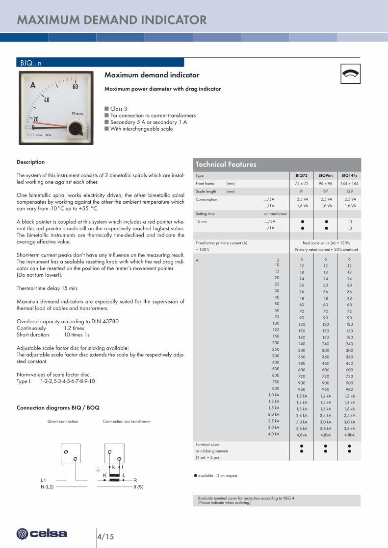
Technical FeaturesType BIQ72 BIQ96n BIQ144s
Front frame (mm) 72 x 72 96 x 96 144 x 144
Scale length (mm) 91 97 139
Consumption .../5A
.../1A
2,5 VA
1,6 VA
2,5 VA
1,6 VA
2,5 VA
1,6 VA
Setting time at transformer
15 min ..../5A
.../1A
l
l
l
l
m
m
Transformer primary current (A)
= 100%
final scale value (A) = 120%
Primary rated current + 20% overload
A 510
15
20
25
30
40
50
60
75
100
125
150
200
250
300
400
500
600
750
800
1,0 kA
1,2 kA
1,5 kA
2,0 kA
2,5 kA
3,0 kA
4,0 kA
6
12
18
24
30
36
48
60
72
90
120
150
180
240
300
360
480
600
720
900
960
1,2 kA
1,4 kA
1,8 kA
2,4 kA
3,0 kA
3,6 kA
4,8kA
6
12
18
24
30
36
48
60
72
90
120
150
180
240
300
360
480
600
720
900
960
1,2 kA
1,4 kA
1,8 kA
2,4 kA
3,0 kA
3,6 kA
4,8kA
6
12
18
24
30
36
48
60
72
90
120
150
180
240
300
360
480
600
720
900
960
1,2 kA
1,4 kA
1,8 kA
2,4 kA
3,0 kA
3,6 kA
4,8kA
Terminal cover
or rubber grommets
(1 set. = 2 pcs.)
l
l
l
l
l
l
BIQ...n
l available m on request
.
Description
The system of this instrument consists of 2 bimetallic spirals which are instal-led working one against each other.
One bimetallic spiral works electricity driven, the other bimetallic spiralcompensates by working against the other the ambient temperature whichcan vary from -10°C up to +55 °C.
A black pointer is coupled at this system which includes a red pointer whe-reat this red pointer stands still on the respectively reached highest value.The bimetallic instruments are thermically time-declined and indicate theaverage effective value.
Short-term current peaks don’t have any influence on the measuring result.The instrument has a sealable resetting knob with which the red drag indi-cator can be resetted on the position of the meter’s movement pointer.(Do not turn lower!).
Thermal time delay 15 min.
Maximun demand indicators are especially suited for the supervision ofthermal load of cables and transformers.
Overload capacity according to DIN 43780Continuously 1.2 timesShort duration 10 times 1s
Adjustable scale factor disc for sticking available:The adjustable scale factor disc extends the scale by the respectively adju-sted constant.
Norm-values of scale factor disc:Type I: 1-2-2,5-3-4-5-6-7-8-9-10
Connection diagrams BIQ / BOQ
Direct connection Connection via transformer
Maximum demand indicator
Maximum power diameter with drag indicator
n Class 3n For connection to current transformersn Secondary 5 A or secondary 1 A n With interchangeable scale
Backside terminal cover for protection according to VBG 4(Please indicate when ordering.)
4/16
ANALO
GUE M
EASU
RIN
G IN
STRU
MEN
TS
MAXIMUM DEMAND INDICATOR 04
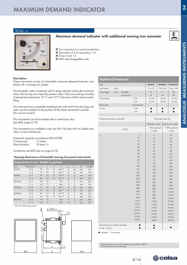
DescriptionThese instruments consist of a bimetallic maximum demand indicator com-bined with a moving iron system.
The bimetallic meter movement with its drag indicator shows the maximumvalue, the moving iron meter the present value. They are working smoothlyat temperatures between -10°C and +55°C because of their robust assem-bling.
The instrument has a sealable resetting knob with which the red drag indi-cator can be resetted on the position of the meter movement’s pointer. (Do not turn lower!).
The instruments can be furnished with a scale factor disc. (see BIQ, page 4/15)
The instruments are available in the size 96 x 96 also with an added satu-ration current transformer.
Overload capacity according to DIN 43780Continuously 1.2 timesShort duration 10 times 1s
Connection see BIQ (see on page 4/15)
Housing dimensions of bimetallic moving iron panel instruments
Dimensiones in mm / Weight in grammeType Dimensions a c d e g h Ø WeightBIQ72n .../5 A 72 55 74 68+0,7 81 4,6 M6 190
.../1 A 72 55 74 68+0,7 81 4,6 M4 190BIQ96n .../5 A 96 55 74 92+0,8 81 5 M6 250
.../1 A 96 55 74 92+0,8 81 5 M8 250BIQ144s .../5 A 144 70 - 138+1 10 8 M4 625
.../1 A 144 70 - 138+1 10 8 M6 750BOQ72n .../5 A 72 55 74 68+0,7 81 4,6 M8 230
.../1 A 72 55 74 68+0,7 81 4,6 M4 220BOQ96n .../5 A 96 55 74 92+0,8 81 5 M6 290
.../1 A 96 55 74 92+0,8 81 5 M8 280BEQ144s .../5 A 144 70 - 138+1 10 8 M4 680
.../1 A 144 70 - 138+1 10 8 M4 795
a
c
d
g13
(max.)
e
h
BOQ...n
l available m on request
Maximun demand indicator with additional moving iron ammeter
n For connection to current transformern Secondary 5 A or secondary 1 A n Class 3 and 1.5n With interchangeable scale
Technical FeaturesType BOQ72 BOQ96n BOQ144s
Front frame (mm) 72 x 72 96 x 96 144 x 144
Scale length (mm) Bimetallic
moving iron
52
61
71
90
90
90
Consumption .../5A
.../1A
3,4 VA
2,5 VA
3,4 VA
2,5 VA
2,7 VA
2,5 VA
Setting time at transformer
15 min ..../5A
.../1A
l
l
l
l
l
l
Transformer primary current (A) final scale value (A)
Bimetallic system Movin iron system
= 100%20% overload
= 120%
100% overload
= 120%
A 510
15
20
25
30
40
50
60
75
100
125
150
200
250
300
400
500
600
750
800
1,0 kA
1,2 kA
1,5 kA
2,0 kA
2,5 kA
3,0 kA
4,0 kA
6
12
18
24
30
36
48
60
72
90
120
150
180
240
300
360
480
600
720
900
960
1,2 kA
1,4 kA
1,8 kA
2,4 kA
3,0 kA
3,6 kA
4,8kA
10
20
30
40
50
60
80
100
120
150
200
250
300
400
500
600
800
1,0 kA
1,2 kA
1,5 kA
1,6 kA
2,0 kA
2,4 kA
3,0 kA
4,0 kA
5,0 kA
6,0 kA
8,0 kA
Terminal cover or rubber grommets l
(1 set. = 2 pcs.) l
l
l
---
l
Backside terminal cover for protection according to VBG 4(Please indicate when ordering.)
1 26 mm with fixing screws
4/17
TRIPLE MOVING INSTRUMENTS
EQ 192 x 96
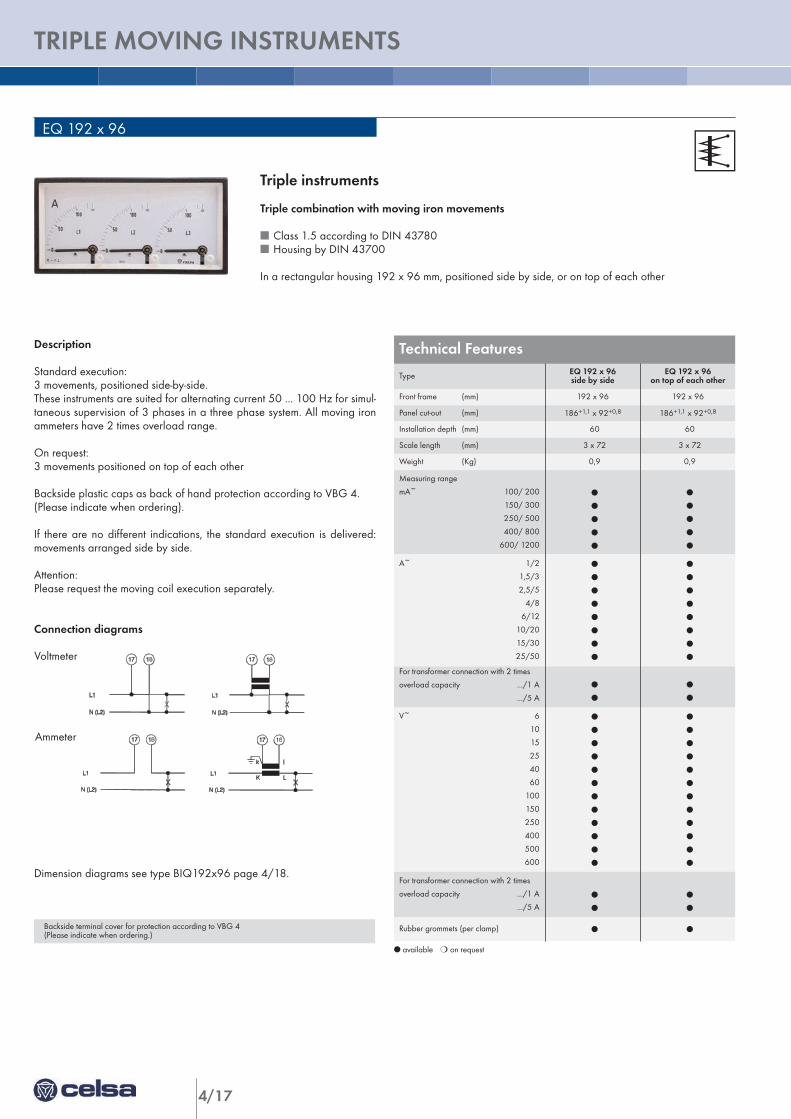
Description
Standard execution:3 movements, positioned side-by-side.These instruments are suited for alternating current 50 ... 100 Hz for simul-taneous supervision of 3 phases in a three phase system. All moving ironammeters have 2 times overload range.
On request:3 movements positioned on top of each other
Backside plastic caps as back of hand protection according to VBG 4.(Please indicate when ordering).
If there are no different indications, the standard execution is delivered:movements arranged side by side.
Attention:Please request the moving coil execution separately.
Connection diagrams
Dimension diagrams see type BIQ192x96 page 4/18.
l available m on request
AC Voltage
AC Current
Triple instruments
Triple combination with moving iron movements
n Class 1.5 according to DIN 43780n Housing by DIN 43700
In a rectangular housing 192 x 96 mm, positioned side by side, or on top of each other
Technical Features
Type EQ 192 x 96side by side
EQ 192 x 96on top of each other
Front frame (mm) 192 x 96 192 x 96
Panel cut-out (mm) 186+1,1 x 92+0,8 186+1,1 x 92+0,8
Installation depth (mm) 60 60
Scale length (mm) 3 x 72 3 x 72
Weight (Kg) 0,9 0,9
Measuring range
mA~ 100/ 200
150/ 300
250/ 500
400/ 800
600/ 1200
l
l
l
l
l
l
l
l
l
l
A~ 1/2
1,5/3
2,5/5
4/8
6/12
10/20
15/30
25/50
l
l
l
l
l
l
l
l
l
l
l
l
l
l
l
l
For transformer connection with 2 times
overload capacity .../1 A
.../5 A
l
l
l
l
V~ 6
10
15
25
40
60
100
150
250
400
500
600
l
l
l
l
l
l
l
l
l
l
l
l
l
l
l
l
l
l
l
l
l
l
l
l
For transformer connection with 2 times
overload capacity .../1 A
.../5 Al
l
l
l
Rubber grommets (per clamp) l l Backside terminal cover for protection according to VBG 4(Please indicate when ordering.)
Voltmeter
Ammeter
4/18
ANALO
GUE M
EASU
RIN
G IN
STRU
MEN
TS
TRIPLE MAXIMUM DEMAND - MOVING IRON AMMETERS 04
Technical Features BOQMaximum flowmeter with bimetallic
movementBOQ 192 x 96side by side
BOQ 192 x 96on top of each other
Front frame (mm) 192 x 96 192 x 96
Panel cut-out (mm) 186+1,1 x 92+0,8 186+1,1 x 92+0,8
Installation depth (mm) 60 60
Scale length (mm) 70 74 70 74
Weight (Kg) 1,0 1,0
3 bimetallic movements
Setting time 15 min l l
on demand 8 min l l
Consumption moving iron and bimetallic
at 1 A nominal current3 x 2 VA 3 x 2 VA
Consumption moving iron and bimetallic
at 5 A nominal current3 x 4 VA 3 x 4 VA
Transformer connection .../1 A
.../5 A
l
l
l
l
Rubber grommets (per clamp) l l
Indicate nominal transformer current
Measuring range end value = 1.2 times
nominal transformer current
Technical Features BIQMaximum ammeter with bimetallic
movementBIQ 192 x 96side by side
BIQ 192 x 96on top of each other
Front frame (mm) 192 x 96 192 x 96
Panel cut-out (mm) 186+1,1 x 92+0,8 186+1,1 x 92+0,8
Installation depth (mm) 60 60
Scale length (mm) 3 x 74 3 x 74
Weight (Kg) 0,7 0,7
3 bimetallic movements
Setting time 15 min l l
on demand 8 min l l
Consumption
at 1 A nominal current3 x 1,3 VA 3 x 1,3 VA
Consumption
at 5 A nominal current3 x 3,5 VA 3 x 3,5 VA
Transformer connection .../1 A
.../5 A
l
l
l
l
Rubber grommets (per clamp) l l
Indicate nominal transformer current
Measuring range end value = 1.2 times the
nominal transformer current
BIQ 192 x 96 / BOQ 192 x 96
BIQ BOQ
l available m on request
l available m on demand
96 90
192
184
60
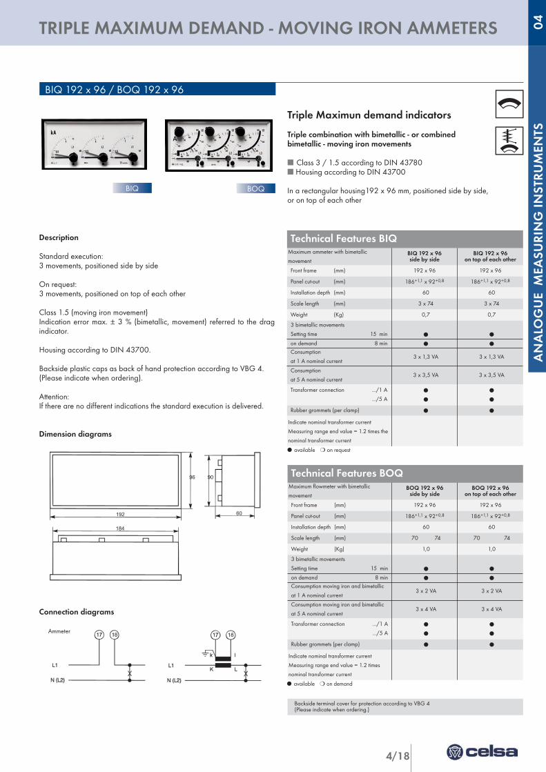
Description
Standard execution:3 movements, positioned side by side
On request:3 movements, positioned on top of each other
Class 1.5 (moving iron movement)Indication error max. ± 3 % (bimetallic, movement) referred to the dragindicator.
Housing according to DIN 43700.
Backside plastic caps as back of hand protection according to VBG 4.(Please indicate when ordering).
Attention:If there are no different indications the standard execution is delivered.
Dimension diagrams
Connection diagrams
Ammeter
Triple Maximun demand indicators
Triple combination with bimetallic - or combinedbimetallic - moving iron movements
n Class 3 / 1.5 according to DIN 43780n Housing according to DIN 43700
In a rectangular housing192 x 96 mm, positioned side by side,or on top of each other
Backside terminal cover for protection according to VBG 4(Please indicate when ordering.)
4/19
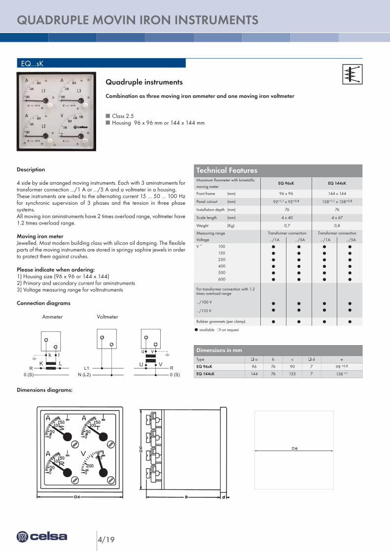
QUADRUPLE MOVIN IRON INSTRUMENTS
EQ...sK
Description
4 side by side arranged moving instruments. Each with 3 aminstruments fortransformer connection .../1 A or .../5 A and a voltmeter in a housing.These instruments are suited to the alternating current 15 ... 50 ... 100 Hzfor synchronic supervision of 3 phases and the tension in three phasesystems. All moving iron aminstruments have 2 times overload range, voltmeter have1.2 times overload range.
Moving iron meterJewelled. Most modern building class with silicon oil damping. The flexibleparts of the moving instruments are stored in springy saphire jewels in orderto protect them against crushes.
Please indicate when ordering:1) Housing size (96 x 96 or 144 x 144)2) Primary and secondary current for aminstruments3) Voltage measuring range for voltinstruments
Connection diagrams
Dimensions diagrams:
l available m on request
e
K Lk l
R0 (S)
vu
VU
N (L2)L1
0 (S)R
VoltmeterAmmeter
Quadruple instruments
Combination as three moving iron ammeter and one moving iron voltmeter
n Class 2.5n Housing 96 x 96 mm or 144 x 144 mm
Technical Features Maximum flowmeter with bimetallic
moving meterEQ 96sK EQ 144sK
Front frame (mm) 96 x 96 144 x 144
Panel cut-out (mm) 92+1,1 x 92+0,8 138+1,1 x 138+0,8
Installation depth (mm) 76 76
Scale length (mm) 4 x 40 4 x 67
Weight (Kg) 0,7 0,8
Measuring range
Voltage
Transformer connection Transformer connection
.../1A .../5A .../1A .../5A
V ~ 100
150
250
400
500
600
l
l
l
l
l
l
l
l
l
l
l
l
l
l
l
l
l
l
l
l
l
l
l
l
For transformer connection with 1.2times overload range
.../100 V
.../110 V
l
l
l
l
l
l
l
l
Rubber grommets (per clamp) l l l l
Dimensions in mm Type q a b c q d e
EQ 96sK 96 76 90 7 98 +0,8
EQ 144sK 144 76 135 7 138 +1
Ammeter Voltmeter

4/20
ANALO
GUE M
EASU
RIN
G IN
STRU
MEN
TS
NOTES 04
4/21
ELECTRONIC ACTIVE POWER INSTRUMENT
Technical FeaturesFront frame (mm) 96 x 96 144 x 144
Scale length (mm) 97 146
Weight (g)
a = 650
b = 650
c = 750
d = 900
a = 900
b = 950
c = 1000
d = 1100
Measuring range U (V) I (A) Type Type
One phasealternating current DQ 96n/1w DQ 144n/1w
a
57,7 - 63,5
100 - 110 - 127
230 - 400
5
1
l
l
l
l
Three-phase current balanced load DQ 96n/1d DQ 144n/1d
b
100 - 110 - 230
400
440 - 500
5
1
l
l
l
l
Three-phase current unbalanced load DQ 96n/2 DQ 144n/2
c
100 - 110 - 230
400
440 - 500
5
1
l
l
l
l
Three-phase 4-wire currentbalanced load DQ 96n/1 DQ 144n/1
a
100 - 110 - 230
400
440 - 500
5
1
l
l
l
l
Three-phase 4-wire current unbalanced load DQ 96n/3 DQ 144n/3
d
100 - 110 - 230
400
440 - 500
5
1
l
l
l
l
Rubber grommets (per clamp) l l
DQ...n
l available m on request
Connection diagrams see page 4/25.
Dimension diagrams at DQ..n/b. (see page 4/22)
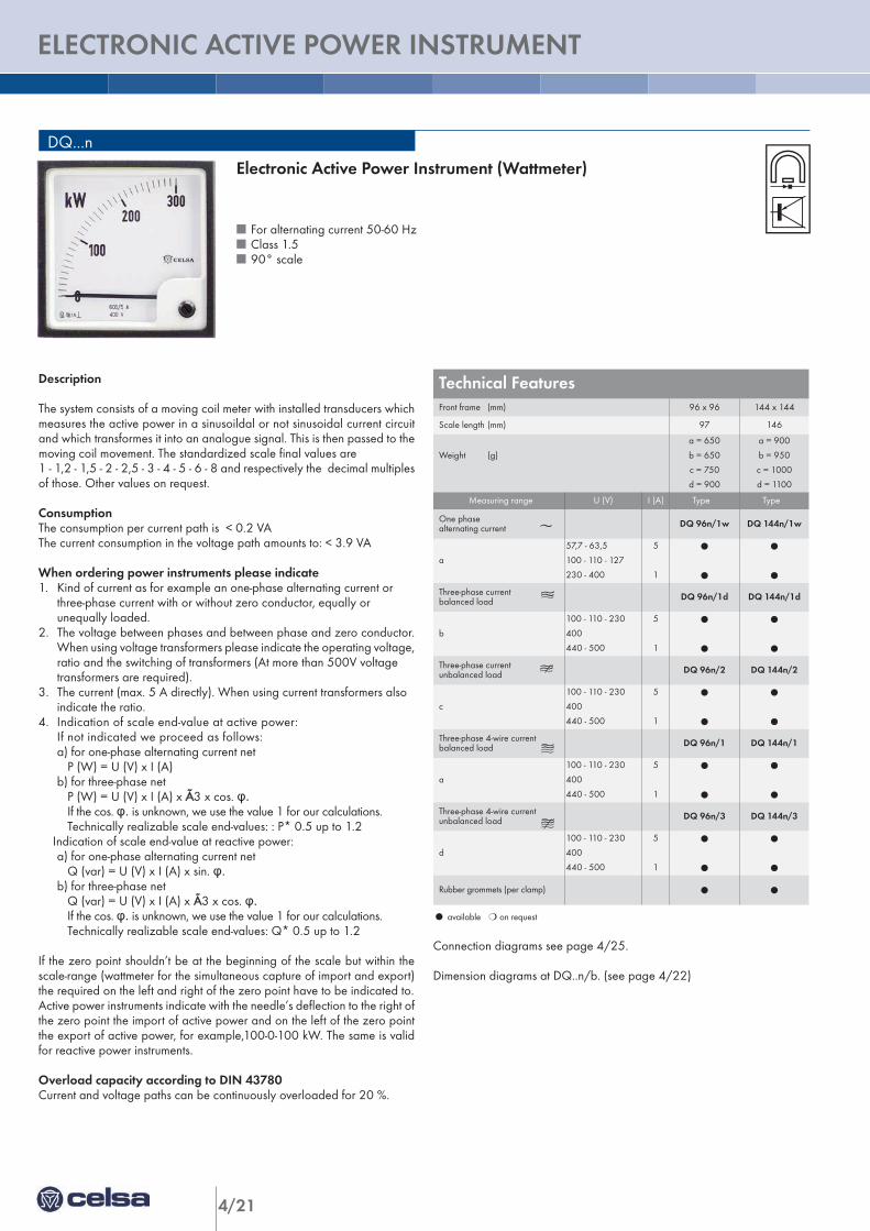
Electronic Active Power Instrument (Wattmeter)
n For alternating current 50-60 Hzn Class 1.5n 90° scale
Description
The system consists of a moving coil meter with installed transducers whichmeasures the active power in a sinusoildal or not sinusoidal current circuitand which transformes it into an analogue signal. This is then passed to themoving coil movement. The standardized scale final values are 1 - 1,2 - 1,5 - 2 - 2,5 - 3 - 4 - 5 - 6 - 8 and respectively the decimal multiplesof those. Other values on request.
ConsumptionThe consumption per current path is < 0.2 VAThe current consumption in the voltage path amounts to: < 3.9 VA
When ordering power instruments please indicate 1. Kind of current as for example an one-phase alternating current or
three-phase current with or without zero conductor, equally or unequally loaded.
2. The voltage between phases and between phase and zero conductor.When using voltage transformers please indicate the operating voltage,ratio and the switching of transformers (At more than 500V voltage transformers are required).
3. The current (max. 5 A directly). When using current transformers also indicate the ratio.
4. Indication of scale end-value at active power: If not indicated we proceed as follows:a) for one-phase alternating current net
P (W) = U (V) x I (A)b) for three-phase net
P (W) = U (V) x I (A) x Ã3 x cos. φ.If the cos. φ. is unknown, we use the value 1 for our calculations.Technically realizable scale end-values: : P* 0.5 up to 1.2
Indication of scale end-value at reactive power:a) for one-phase alternating current net
Q (var) = U (V) x I (A) x sin. φ.b) for three-phase net
Q (var) = U (V) x I (A) x Ã3 x cos. φ.If the cos. φ. is unknown, we use the value 1 for our calculations.Technically realizable scale end-values: Q* 0.5 up to 1.2
If the zero point shouldn’t be at the beginning of the scale but within thescale-range (wattmeter for the simultaneous capture of import and export)the required on the left and right of the zero point have to be indicated to.Active power instruments indicate with the needle’s deflection to the right ofthe zero point the import of active power and on the left of the zero pointthe export of active power, for example,100-0-100 kW. The same is validfor reactive power instruments.
Overload capacity according to DIN 43780Current and voltage paths can be continuously overloaded for 20 %.
4/22
ANALO
GUE M
EASU
RIN
G IN
STRU
MEN
TS
ELECTRONIC REATIVE POWER METER 04
Technical FeaturesFront frame (mm) 96 x 96 144 x 144
Scale length (mm) 97 146
Weight (g)
a = 460
b = 510
c = 695
d = 725
a = 720
b = 770
c = 960
d = 990
Measuring range U (V) I (A) Type Type
One phasealternating current DQ 96n/1wb DQ 144n/1wb
a
57,7 - 63,5
100 - 110 - 127
230 - 400
5
1
l
l
l
l
Three-phase current balanced load DQ 96n/1db DQ 144n/1db
b
100 - 110 - 230
400
440 - 500
5
1
l
l
l
l
Three-phase current unbalanced load DQ 96n/2b DQ 144n/2b
c
100 - 110 - 230
400
440 - 500
5
1
l
l
l
l
Three-phase 4-wire currentbalanced load DQ 96n/1b DQ 144n/1b
a
100 - 110 - 230
400
440 - 500
5
1
l
l
l
l
Three-phase 4-wire current unbalanced load DQ 96n/3b DQ 144n/3b
d
100 - 110 - 230
400
440 - 500
5
1
l
l
l
l
Rubber grommets (per clamp) l l
DQ..n/b
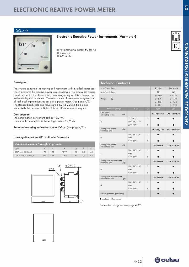
Description
The system consists of a moving coil movement with installed transducerwhich measures the reactive power in a sinusoidal or not sinusoidal currentcircuit and which transforms it into an analogue signal. This is then passedto the moving coil movement. These instruments have the same system andall technical explanations as our active power meter. (See page 4/21)The standardized scale end-values are 1-1,2-1,5-2-2,5-3-4-5-6-8 and respectively the decimal multiples of those. Other values on request.
ConsumptionThe consumption per current path is < 0,2 VAThe current consumption in the voltage path is < 3,9 VA
Required ordering indications see at DQ..n. (see page 4/21)
Housing dimensions 90° wattmeter/varmeter
l available m on request
Connection diagrams see page 4/25.
Electronic Reactive Power Instruments (Varmeter)
n For alternating current 50-60 Hzn Class 1.5n 90° scale
Dimensions in mm / Weight in grammeType a c e g h Ø
DQ 96n / DQ 96n/b 96 134 92+0,8 40 5,5 M4
DQ 144n / DQ 144n/b 144 134 138 +1 40 5,5 M4
a c
g (max.)
eh
IP10
a c
g (max.)
eh
IP10
4/23
ELECTRONIC ACTIVE POWER INSTRUMENT
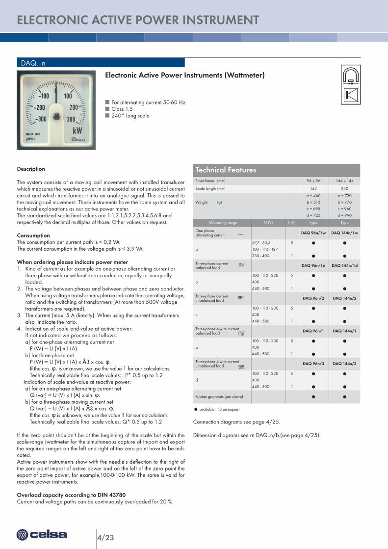
Description
The system consists of a moving coil movement with installed transducerwhich measures the reactive power in a sinusoidal or not sinusoidal currentcircuit and which transformes it into an analogue signal. This is possed tothe moving coil movement. These instruments have the same system and alltechnical explanations as our active power meter.The standardized scale final values are 1-1,2-1,5-2-2,5-3-4-5-6-8 and respectively the decimal multiples of those. Other values on request.
ConsumptionThe consumption per current path is < 0,2 VAThe current consumption in the voltage path is < 3,9 VA
When ordering please indicate power meter1. Kind of current as for example an one-phase alternating current or
three-phase with or without zero conductor, equally or unequally loaded.
2. The voltage between phases and between phase and zero conductor.When using voltage transformers please indicate the operating voltage,ratio and the switching of transformers (At more than 500V voltage transformers are required).
3. The current (max. 5 A directly). When using the current transformers also indicate the ratio.
4. Indication of scale end-value at active power: If not indicated we proceed as follows:a) for one-phase alternating current net
P (W) = U (V) x I (A)b) for three-phase net
P (W) = U (V) x I (A) x Ã3 x cos. φ.If the cos. φ. is unknown, we use the value 1 for our calculations.Technically realizable final scale values: : P* 0.5 up to 1.2
Indication of scale end-value at reactive power:a) for an one-phase alternating current net
Q (var) = U (V) x I (A) x sin. φ.b) for a three-phase moving current net
Q (var) = U (V) x I (A) x Ã3 x cos. φ.If the cos. φ is unknown, we use the value 1 for our calculations.Technically realizable final scale values: Q* 0.5 up to 1.2
If the zero point shouldn’t be at the beginning of the scale but within thescale-range (wattmeter for the simultaneous capture of import and exportthe required ranges on the left and right of the zero point have to be indi-cated.Active power instruments show with the needle’s deflection to the right ofthe zero point import of active power and on the left of the zero point theexport of active power, for example,100-0-100 kW. The same is valid forreactive power instruments.
Overload capacity according to DIN 43780Current and voltage paths can be continuously overloaded for 20 %.
Technical FeaturesFront frame (mm) 96 x 96 144 x 144
Scale length (mm) 142 230
Weight (g)
a = 460
b = 510
c = 695
d = 725
a = 720
b = 770
c = 960
d = 990
Measuring range U (V) I (A) Type Type
One phasealternating current DAQ 96n/1w DAQ 144n/1w
a
57,7 - 63,5
100 - 110 - 127
230 - 400
5
1
l
l
l
l
Three-phase current balanced load DAQ 96n/1d DAQ 144n/1d
b
100 - 110 - 230
400
440 - 500
5
1
l
l
l
l
Three-phase current unbalanced load DAQ 96n/2 DAQ 144n/2
c
100 - 110 - 230
400
440 - 500
5
1
l
l
l
l
Three-phase 4-wire currentbalanced load DAQ 96n/1 DAQ 144n/1
a
100 - 110 - 230
400
440 - 500
5
1
l
l
l
l
Three-phase 4-wire current unbalanced load DAQ 96n/3 DAQ 144n/3
d
100 - 110 - 230
400
440 - 500
5
1
l
l
l
l
Rubber grommets (per clamp) l l
DAQ...n
l available m on request
Connection diagrams see page 4/25.
Dimension diagrams see at DAQ..n/b.(see page 4/25).
Electronic Active Power Instruments (Wattmeter)
n For alternating current 50-60 Hzn Class 1.5n 240° long scale
4/24
ANALO
GUE M
EASU
RIN
G IN
STRU
MEN
TS
ELECTRONIC REACTIVE INSTRUMENT 04
DAQ..n/b
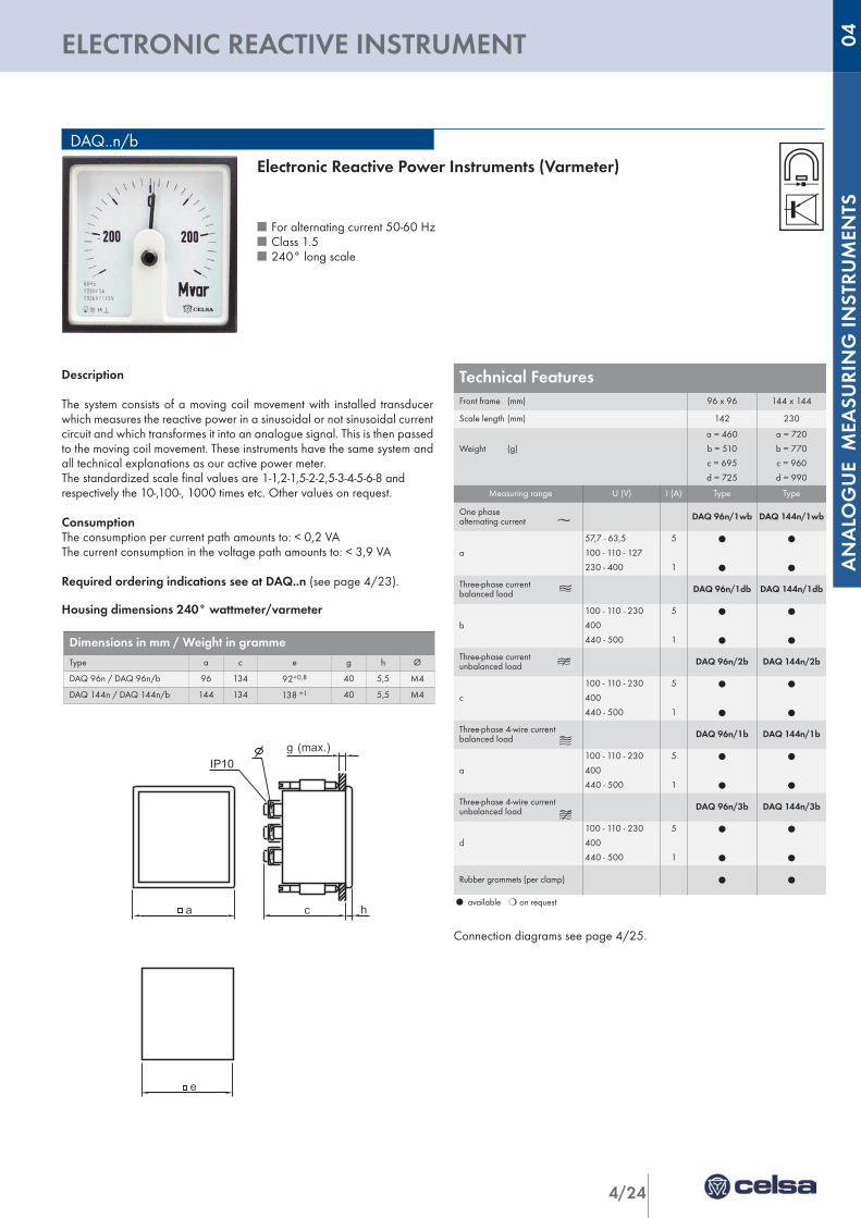
Description
The system consists of a moving coil movement with installed transducerwhich measures the reactive power in a sinusoidal or not sinusoidal currentcircuit and which transformes it into an analogue signal. This is then passedto the moving coil movement. These instruments have the same system andall technical explanations as our active power meter.The standardized scale final values are 1-1,2-1,5-2-2,5-3-4-5-6-8 and respectively the 10-,100-, 1000 times etc. Other values on request.
ConsumptionThe consumption per current path amounts to: < 0,2 VAThe current consumption in the voltage path amounts to: < 3,9 VA
Required ordering indications see at DAQ..n (see page 4/23).
Housing dimensions 240° wattmeter/varmeter
l available m on request
Connection diagrams see page 4/25.
Electronic Reactive Power Instruments (Varmeter)
n For alternating current 50-60 Hzn Class 1.5n 240° long scale
a c
g (max.)
eh
IP10
Dimensions in mm / Weight in grammeType a c e g h Ø
DAQ 96n / DAQ 96n/b 96 134 92+0,8 40 5,5 M4
DAQ 144n / DAQ 144n/b 144 134 138 +1 40 5,5 M4
Technical FeaturesFront frame (mm) 96 x 96 144 x 144
Scale length (mm) 142 230
Weight (g)
a = 460
b = 510
c = 695
d = 725
a = 720
b = 770
c = 960
d = 990
Measuring range U (V) I (A) Type Type
One phasealternating current DAQ 96n/1wb DAQ 144n/1wb
a
57,7 - 63,5
100 - 110 - 127
230 - 400
5
1
l
l
l
l
Three-phase current balanced load DAQ 96n/1db DAQ 144n/1db
b
100 - 110 - 230
400
440 - 500
5
1
l
l
l
l
Three-phase current unbalanced load DAQ 96n/2b DAQ 144n/2b
c
100 - 110 - 230
400
440 - 500
5
1
l
l
l
l
Three-phase 4-wire currentbalanced load DAQ 96n/1b DAQ 144n/1b
a
100 - 110 - 230
400
440 - 500
5
1
l
l
l
l
Three-phase 4-wire current unbalanced load DAQ 96n/3b DAQ 144n/3b
d
100 - 110 - 230
400
440 - 500
5
1
l
l
l
l
Rubber grommets (per clamp) l l
a c
g (max.)
eh
IP10
4/25
POWER INSTRUMENTS/ POWER FACTOR INSTRUMENTS
Active power instrument
Reactive power instrument
Power factor instrument
Power factor instrument
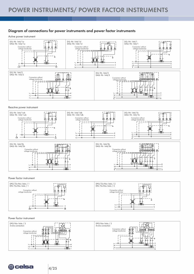
Diagram of connections for power instruments and power factor instruments
DQ -96 -144/1wDAQ -96 -144/1w
Connection withoutvoltage transformer
DQ -96 -144/1dDAQ -96 -144/1d
Connection withoutvoltage transformer
DQ -96 -144/1DAQ -96 -144/1
Connection withoutvoltage transformer
DQ -96 -144/1wbDAQ -96 -144/1wb
Connection withoutvoltage transformer
DQ -96 -144/1dbDAQ -96 -144/1db
Connection withoutvoltage transformer
DQ -96 -144/1bDAQ -96 -144/1b
Connection withoutvoltage transformer
DQ -96 -144/2DAQ -96 -144/2
Connection withoutvoltage transformer
DQ -96 -144/3DAQ -96 -144/3
Connection withoutvoltage transformer
DQ -96 -144/2bDAQ -96 -144/2b
Connection withoutvoltage transformer
DQ -96 -144/3bDAQ -96 -144/3b
Connection withoutvoltage transformer
DPQ 72n-96n-144n / 1EPA 72n-96n-144n / 1
Connection withoutvoltage transformer
DPQ 96n-144n / 33-wire connection
Connection withoutvoltage transformer
DPQ 96n-144n / 34-wire connection
Connection withoutvoltage transformer
DPQ 72n-96n-144n / 2EPA 72n-96n-144n / 2
Connection withoutvoltage transformer
4/26
ANALO
GUE M
EASU
RIN
G IN
STRU
MEN
TS
POWER FACTOR INSTRUMENTS 04
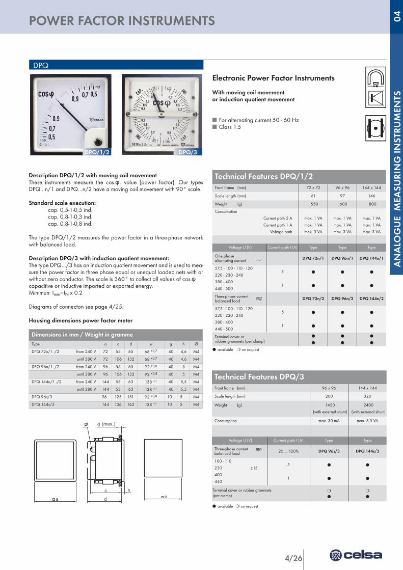
Technical Features DPQ/3Front frame (mm) 96 x 96 144 x 144
Scale length (mm) 200 320
Weight (g) 1450
(with external shunt)
2400
(with external shunt)
Consumption max. 30 mA max. 3.5 VA
Voltage U (V) Current path I (A) Type Type
Three-phase current balanced load 20 ... 120% DPQ 96s/3 DPQ 144s/3
100 - 110
230 ±15
400
440
5
1
l
l
l
l
Terminal cover or rubber grommets (per clamp)
m
l
m
l
Description DPQ/1/2 with moving coil movementThese instruments measure the cos.φ. value (power factor). Our typesDPQ…n/1 and DPQ…n/2 have a moving coil movement with 90° scale.
Standard scale execution:cap. 0,5-1-0,5 ind.cap. 0,8-1-0,3 ind.cap. 0,8-1-0,8 ind.
The type DPQ/1/2 measures the power factor in a three-phase networkwith balanced load.
Description DPQ/3 with induction quotient movement:The type DPQ…/3 has an induction quotient movement and is used to mea-sure the power factor in three phase equal or unequal loaded nets with orwithout zero conductor. The scale is 360° to collect all values of cos.φcapacitive or inductive imported or exported energy.Minimun: Imin=IN x 0.2
Diagrams of connecton see page 4/25.
Housing dimensions power factor meter
DPQ
l available m on request
Electronic Power Factor Instruments
With moving coil movement or induction quotient movement
n For alternating current 50 - 60 Hzn Class 1.5
l available m on request
Technical Features DPQ/1/2Front frame (mm) 72 x 72 96 x 96 144 x 144
Scale length (mm) 61 97 146
Weight (g) 550 600 800
Consumption
Current path 5 A
Current path 1 A
Voltage path
max. 1 VA
max. 1 VA
max. 3 VA
max. 1 VA
max. 1 VA
max. 3 VA
max. 1 VA
max. 1 VA
max. 3 VA
Voltage U (V) Current path I (A) Type Type Type
One phasealternating current DPQ 72n/1 DPQ 96n/1 DPQ 144n/1
57,5 - 100 - 110 - 120
220 - 230 - 240
380 - 400
440 - 500
5
1
l
l
l
l
l
l
Three-phase current balanced load DPQ 72n/2 DPQ 96n/2 DPQ 144n/2
57,5 - 100 - 110 - 120
220 - 230 - 240
380 - 400
440 - 500
5
1
l
l
l
l
l
l
Terminal cover orrubber grommets (per clamp)
l
l
l
l
l
l
Dimensions in mm / Weight in grammeType a c d e g h Ø
DPQ 72n/1 -/2 from 240 V 72 55 65 68 +0,7 40 4,6 M4
until 380 V 72 106 132 68 +0,7 40 4,6 M4
DPQ 96n/1 -/2 from 240 V 96 55 65 92 +0,8 40 5 M4
until 380 V 96 106 132 92 +0,8 40 5 M4
DPQ 144n/1 -/2 from 240 V 144 53 63 138 +1 40 5,5 M4
until 380 V 144 53 63 138 +1 40 5,5 M4
DPQ 96s/3 96 125 151 92 +0,8 10 5 M4
DPQ 144s/3 144 136 162 138 +1 10 5 M4
DPQ/1/2 DPQ/3
a d
c c
d
gg
13(max.)
(max.)
e
EQ EQSC3V
hha d
c c
d
gg
13(max.)
(max.)
e
EQ EQSC3V
hh
4/27
POWER FACTOR INSTRUMENTS
Technical Features Front frame (mm) 72 x 72 96 x 96 144 x 144
Scale length (mm) 106 142 230
Weight (g) 550 680 800
Voltage U (V) Current path I (A) Type Type Type
One phasealternating current EPA 72n/1 EPA 96n/1 EPA 144n/1
57,7 - 100 - 110 - 120
220 - 230 240
380 - 400
440 - 500
5
1
l
l
l
l
l
l
Three-phase current balanced load EPA 72n/2 EPA 96n/2 EPA 144n/2
57,7 - 100 - 110 - 120
220 - 230 240
380 - 400
440 - 500
5
1
l
l
l
l
l
l
Terminal cover orrubber grommets (per clamp)
m
l
m
l
m
l
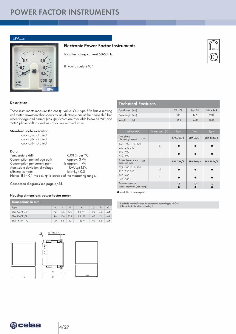
Description
These instruments measure the cos φ. value. Our type EPA has a movingcoil meter movement that shows by an electronic circuit the phase shift bet-ween voltage and current (cos. φ). Scales are available between 90° and260° phase shift, as well as capacitive and inductive.
Standard scale execution:cap. 0,5-1-0,5 ind.cap. 0,8-1-0,3 ind.cap. 0,8-1-0,8 ind.
Data:Temperature drift 0,08 % per °C.Consumption per voltage path approx. 3 VAConsumption per current path approx. 1 VAAdmissible deviation of voltage U=UN ±15%Minimal current: Imin=IN x 0,2Notice: If I < 0,1 the cos. φ. is outside of the measuring range.
Connection diagrams see page 4/25.
Housing dimensions power factor meter
EPA...n
Electronic Power Factor Instruments
For alternating current 50-60 Hz
n Round scale 240°
l available m on request
Backside terminal cover for protection according to VBG 4(Please indicate when ordering.)
Dimensions in mmType a c d e g h Ø
EPA 72n/1 -/2 72 106 132 68 +0,7 40 4,6 M4
EPA 96n/1 -/2 96 106 132 92 +0,8 40 5 M4
EPA 144n/1 -/2 144 53 63 138 +1 40 5,5 M4
EPA
a d
c c
d
gg
13(max.)
(max.)
e
EQ EQSC3V
hha d
c c
d
gg
13(max.)
(max.)
e
EQ EQSC3V
hh
4/28
ANALO
GUE M
EASU
RIN
G IN
STRU
MEN
TS
ANALOGUE MEASURING INSTRUMENTS 04
Technical Features Type ISE 72n/1 ISE 96n/1 ISE 96fs/2
Front frame (mm) 72 x 72 96 x 96 96 x 96
Weight (g) 200 250 600
Consumption 1,5 1,5 1,5
Voltage (V)
150 - 600 V
110 V
230 V
400 V
440 V
500 V
l
---
---
---
---
---
l
---
---
---
---
---
---
m
m
l
m
m
Terminal cover or rubber grommets (per clamp)
l
l
l
l
l
l
ISE
Housing dimensions phase sequence indicators
l available m on request
26-11-01RAGA Esquema de conexion del 3121001BISE/1 del 72
L1
L2 L3
L1
L2
(T) (S) (R)
L3
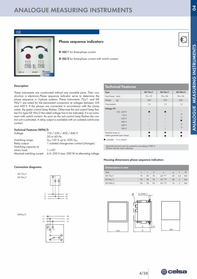
Phase sequence indicators
n ISE/1 for three-phase current
n ISE/2 for three-phase current with switch contact
L1 L2 L3
22-6-95 RAGA Esquema de conexion del
3122001
(R) (S) (T)
ISE/2
L2 L3 L1
Description
These instruments are constructed without any movable parts. Their con-struction is electronic.Phase sequence indicator serve to determine thephase sequence in 3-phase systems. These instruments 72s/1 and ISE96s/1 are suited for the permanent connection at voltages between 150and 600 V. If the phases are connected in accordance with the clampname the green control lamp flashes. Otherwise the red control lamp flas-hes.For type ISE 96s/2 the rated voltage has to be indicated. It is an instru-ment with switch contact. As soon as the red control lamp flashes the con-trol unit is activated. A relay output is available with an isolated switch-overcontact.
Technical Features ISE96/2:Voltage: 110 / 230 / 400 / 440 V
50 or 60 HzSwitching range: UN +20 % up to -20% UNRelay output: 1 isolated change-over contact (changer)Switching capacity at ohmic load: 1 x10⁶.Maximal switching current: 6 A, 250 V max. 300 W at alternating voltage
Connection diagrams:
ISE 72n/1
ISE 96n/1
ISE96s/2
Backside terminal cover for protection according to VBG 4(Please indicate when ordering.)
Dimensions in mmType a c d e g h Ø
ISE 72n/1 72 58 76 68 +0,7 40 4,6 M4
ISE 96n/1 96 58 76 92 +0,8 40 5 M4
ISE 96fs/2 96 78 95 92 +0,8 10 5 M4
ISE
a d
c c
d
gg
13(max.)
(max.)
e
EQ EQSC3V
hha d
c c
d
gg
13(max.)
(max.)
e
EQ EQSC3V
hh
4/29
REED TYPE FREQUENCY INSTRUMENTS
1 26 mm with fixing screws
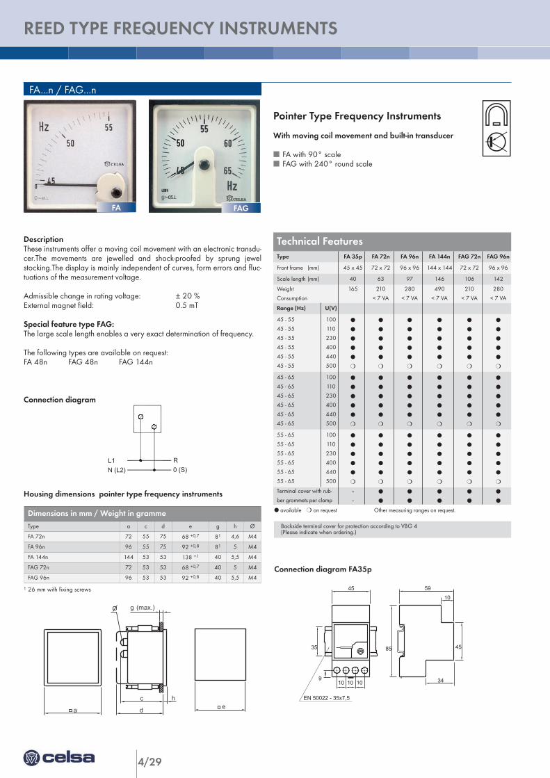
DescriptionThese instruments offer a moving coil movement with an electronic transdu-cer.The movements are jewelled and shock-proofed by sprung jewelstocking.The display is mainly independent of curves, form errors and fluc-tuations of the measurement voltage.
Admissible change in rating voltage: ± 20 %External magnet field: 0.5 mT
Special feature type FAG:The large scale length enables a very exact determination of frequency.
The following types are available on request:FA 48n FAG 48n FAG 144n
Connection diagram
Housing dimensions pointer type frequency instruments
FA...n / FAG...n
l available m on request Other measuring ranges on request.
Connection diagram FA35p
N (L2)L1
0 (S)RR
0 (S)N (L2)L1
Pointer Type Frequency Instruments
With moving coil movement and built-in transducer
n FA with 90° scalen FAG with 240° round scale
EQ35GPQ35GFA35G
10 10 109
35
45 59
10
34
4585
EN 50022 - 35x7,5
Technical Features Type FA 35p FA 72n FA 96n FA 144n FAG 72n FAG 96n
Front frame (mm) 45 x 45 72 x 72 96 x 96 144 x 144 72 x 72 96 x 96
Scale length (mm) 40 63 97 146 106 142
Weight
Consumption
165 210
< 7 VA
280
< 7 VA
490
< 7 VA
210
< 7 VA
280
< 7 VA
Range (Hz) U(V)
45 - 55
45 - 55
45 - 55
45 - 55
45 - 55
45 - 55
100
110
230
400
440
500
l
l
l
l
l
m
l
l
l
l
l
m
l
l
l
l
l
m
l
l
l
l
l
m
l
l
l
l
l
m
l
l
l
l
l
m
45 - 65
45 - 65
45 - 65
45 - 65
45 - 65
45 - 65
100
110
230
400
440
500
l
l
l
l
l
m
l
l
l
l
l
m
l
l
l
l
l
m
l
l
l
l
l
m
l
l
l
l
l
m
l
l
l
l
l
m
55 - 65
55 - 65
55 - 65
55 - 65
55 - 65
55 - 65
100
110
230
400
440
500
l
l
l
l
l
m
l
l
l
l
l
m
l
l
l
l
l
m
l
l
l
l
l
m
l
l
l
l
l
m
l
l
l
l
l
m
Terminal cover with rub-
ber grommets per clamp
--
--
l
l
l
l
l
l
l
l
l
l
Backside terminal cover for protection according to VBG 4(Please indicate when ordering.)
Dimensions in mm / Weight in grammeType a c d e g h Ø
FA 72n 72 55 75 68 +0,7 81 4,6 M4
FA 96n 96 55 75 92 +0,8 81 5 M4
FA 144n 144 53 53 138 +1 40 5,5 M4
FAG 72n 72 53 53 68 +0,7 40 5 M4
FAG 96n 96 53 53 92 +0,8 40 5,5 M4
FAGFA
a d
c c
d
gg
13(max.)
(max.)
e
EQ EQSC3V
hha d
c c
d
gg
13(max.)
(max.)
e
EQ EQSC3V
hh
4/30
ANALO
GUE M
EASU
RIN
G IN
STRU
MEN
TS
REED TYPE FREQUENCY INSTRUMENTS 04
Technical Features FDType FD 96s F 96n
Front frame (mm) 96 x 96 96 x 96
Weight (g) 880 1260
Consumption max. 2 x 2.3 VA max. 2 x 2.3 VA
Measuring range (Hz) U (V) Reeds
2 x 46 ... 50 ... 54
2 x 110
2 x 230
2 x 400
2 x 440
2 x 17
l
l
l
l
m
m
m
m
2x 45 ... 50 ... 55
2 x 110
2 x 230
2 x 400
2 x 440
2 x 21
m
m
m
m
l
l
l
l
2 x 56 ... 60 ... 64
2 x 110
2 x 230
2 x 400
2 x 440
2 x 17
l
l
l
l
m
m
m
m
2 x 50 ... 60 ... 65
2 x 110
2 x 230
2 x 400
2 x 440
2 x 21
m
m
m
m
l
l
l
l
Terminal cover or
rubber grommets (per clamp)
l
l
m
l
FD
N (L2)L1
0 (S)R R R0
(S)
L1 N(L2)
L1 N(L2)
(S)0
F / FD
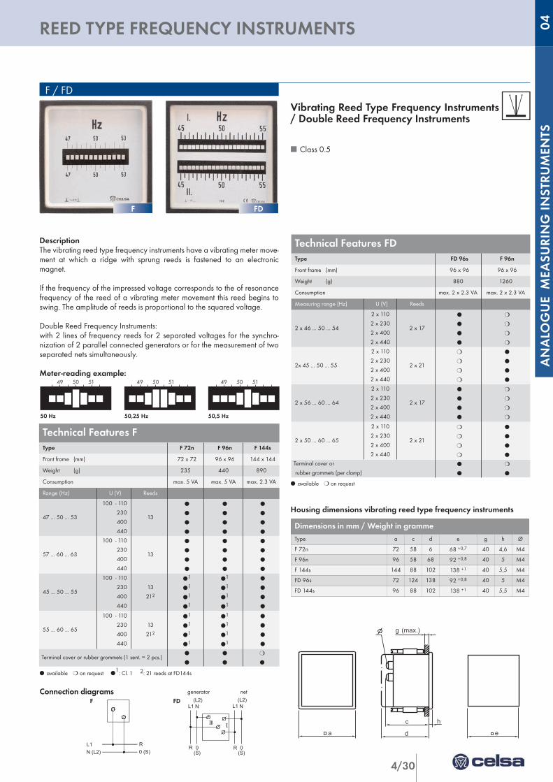
DescriptionThe vibrating reed type frequency instruments have a vibrating meter move-ment at which a ridge with sprung reeds is fastened to an electronicmagnet.
If the frequency of the impressed voltage corresponds to the of resonancefrequency of the reed of a vibrating meter movement this reed begins toswing. The amplitude of reeds is proportional to the squared voltage.
Double Reed Frequency Instruments:with 2 lines of frequency reeds for 2 separated voltages for the synchro-nization of 2 parallel connected generators or for the measurement of twoseparated nets simultaneously.
Meter-reading example:49 50 51 49 50 51 49 50 51
50 Hz 50,25 Hz 50,5 Hz
l available m on request l1: Cl. 1 2: 21 reeds at FD144s
Connection diagrams generator net
F FD
l available m on request
Housing dimensions vibrating reed type frequency instruments
Vibrating Reed Type Frequency Instruments/ Double Reed Frequency Instruments
n Class 0.5
a d
c
g (max.)
e
h
PQ / PAQ
Technical Features FType F 72n F 96n F 144s
Front frame (mm) 72 x 72 96 x 96 144 x 144
Weight (g) 235 440 890
Consumption max. 5 VA max. 5 VA max. 2.3 VA
Range (Hz) U (V) Reeds
47 ... 50 ... 53
100 - 110
230
400
440
13
l
l
l
l
l
l
l
l
l
l
l
l
57 ... 60 ... 63
100 - 110
230
400
440
13
l
l
l
l
l
l
l
l
l
l
l
l
45 ... 50 ... 55
100 - 110
230
400
440
13
212
l1
l1
l1
l1
l1
l1
l1
l1
l
l
l
l
55 ... 60 ... 65
100 - 110
230
400
440
13
212
l1
l1
l1
l1
l1
l1
l1
l1
l
l
l
l
Terminal cover or rubber grommets (1 sent. = 2 pcs.)l
l
l
l
m
l
Dimensions in mm / Weight in grammeType a c d e g h Ø
F 72n 72 58 6 68 +0,7 40 4,6 M4
F 96n 96 58 68 92 +0,8 40 5 M4
F 144s 144 88 102 138 +1 40 5,5 M4
FD 96s 72 124 138 92 +0,8 40 5 M4
FD 144s 96 88 102 138 +1 40 5,5 M4
FDF
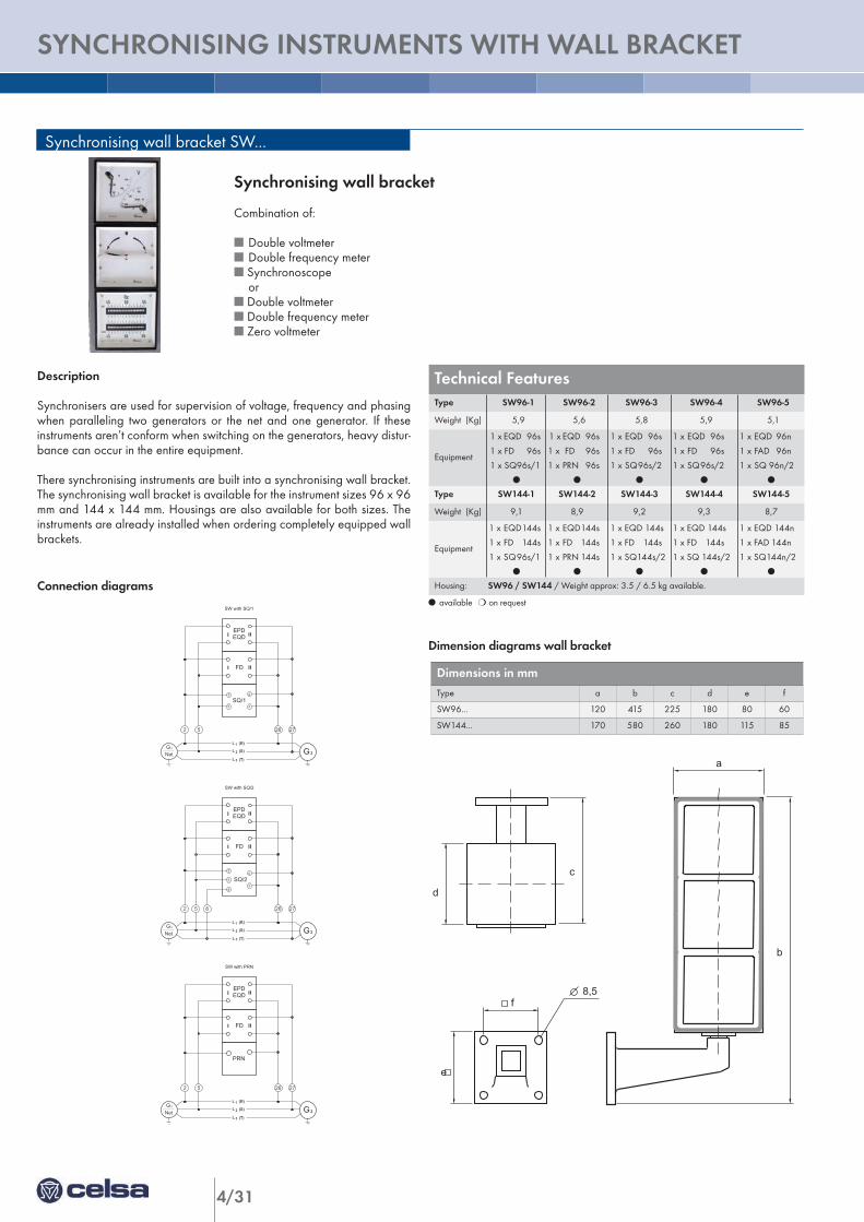
4/31
SYNCHRONISING INSTRUMENTS WITH WALL BRACKET
Synchronising wall bracket SW...
Description
Synchronisers are used for supervision of voltage, frequency and phasingwhen paralleling two generators or the net and one generator. If theseinstruments aren’t conform when switching on the generators, heavy distur-bance can occur in the entire equipment.
There synchronising instruments are built into a synchronising wall bracket.The synchronising wall bracket is available for the instrument sizes 96 x 96mm and 144 x 144 mm. Housings are also available for both sizes. Theinstruments are already installed when ordering completely equipped wallbrackets.
Connection diagramsl available m on request
Dimension diagrams wall bracket
7
84
c
40
180°200
40
a
b
c
8,5
d
e
f
59
10
45
SW with SQ/1
SW mit SQ.../2, < 120 V
2
5 3
4
2 5
G
2726
2
L
L
L
1
2
3
(R)
(S)
(T)
SQ/1
FD
EPDEQD
G1
Net
Synchronising wall bracket
Combination of:
n Double voltmetern Double frequency metern Synchronoscope
orn Double voltmetern Double frequency metern Zero voltmeter
SW mit PRN
SW mit SQ.../2, < 120 V
2
5
83
4
G
2 5 8
G
2726
21
L
L
L
1
2
3
(R)
(S)
(T)
SQ/2
FD
EPDEQD
Net
SW with SQ/2
SW mit PRN
SW mit SQ.../2, < 120 V
2 5
G
2726
2
L
L
L
1
2
3
(R)
(S)
(T)
PRN
FD
EPDEQD
SW with PRN
G1
Net
Dimensions in mm Type a b c d e f
SW96... 120 415 225 180 80 60
SW144... 170 580 260 180 115 85
Technical Features Type SW96-1 SW96-2 SW96-3 SW96-4 SW96-5
Weight (Kg) 5,9 5,6 5,8 5,9 5,1
Equipment
1 x EQD 96s
1 x FD 96s
1 x SQ96s/1
l
1 x EQD 96s
1 x FD 96s
1 x PRN 96s
l
1 x EQD 96s
1 x FD 96s
1 x SQ96s/2
l
1 x EQD 96s
1 x FD 96s
1 x SQ96s/2
l
1 x EQD 96n
1 x FAD 96n
1 x SQ 96n/2
l
Type SW144-1 SW144-2 SW144-3 SW144-4 SW144-5
Weight (Kg) 9,1 8,9 9,2 9,3 8,7
Equipment
1 x EQD144s
1 x FD 144s
1 x SQ96s/1
l
1 x EQD144s
1 x FD 144s
1 x PRN 144s
l
1 x EQD 144s
1 x FD 144s
1 x SQ144s/2
l
1 x EQD 144s
1 x FD 144s
1 x SQ 144s/2
l
1 x EQD 144n
1 x FAD 144n
1 x SQ144n/2
l
Housing: SW96 / SW144 / Weight approx: 3.5 / 6.5 kg available.
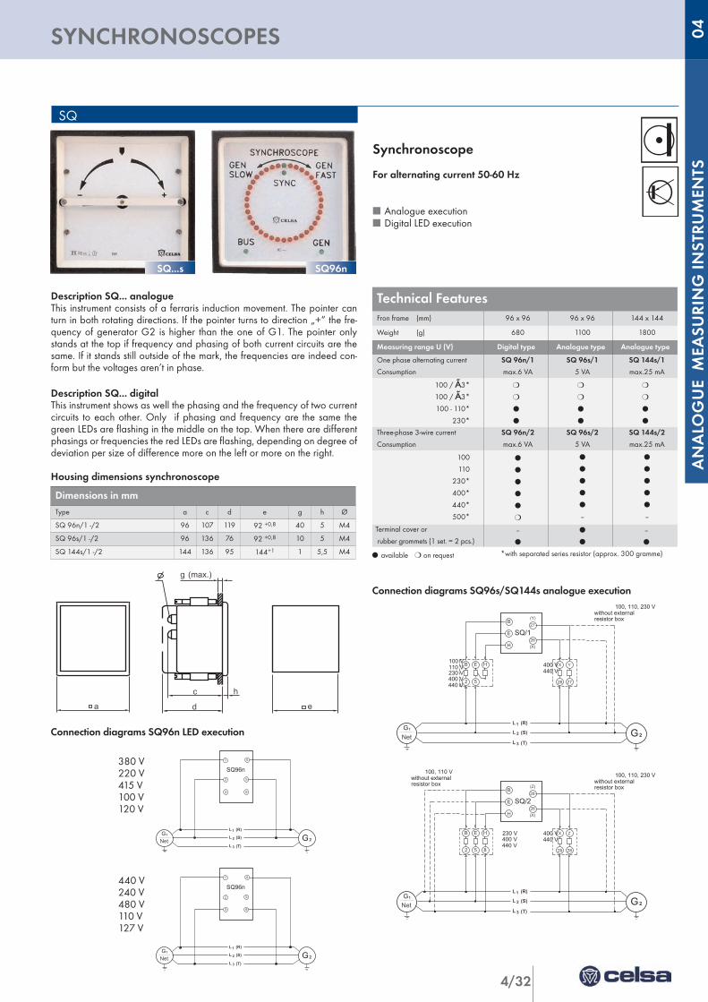
4/32
ANALO
GUE M
EASU
RIN
G IN
STRU
MEN
TS
SYNCHRONOSCOPES 04
SQ
Description SQ... analogueThis instrument consists of a ferraris induction movement. The pointer canturn in both rotating directions. If the pointer turns to direction „+“ the fre-quency of generator G2 is higher than the one of G1. The pointer onlystands at the top if frequency and phasing of both current circuits are thesame. If it stands still outside of the mark, the frequencies are indeed con-form but the voltages aren’t in phase.
Description SQ... digitalThis instrument shows as well the phasing and the frequency of two currentcircuits to each other. Only if phasing and frequency are the same thegreen LEDs are flashing in the middle on the top. When there are differentphasings or frequencies the red LEDs are flashing, depending on degree ofdeviation per size of difference more on the left or more on the right.
Housing dimensions synchronoscope
B
E
H
G
27
26
2
L
L
L
1
2
3
(R)
(S)
(T)
SQ/1
2 5
B E H
G1
Net
26 27
X Y
(X)
(Y)
100, 110, 230 Vwithout externalresistor box
230 V400 V440 V
400 V440 V
100 V110 V
l available m on request *with separated series resistor (approx. 300 gramme)
Connection diagrams SQ96s/SQ144s analogue execution
Synchronoscope
For alternating current 50-60 Hz
n Analogue executionn Digital LED execution
B
E
H
G
28
26
2
L
L
L
1
2
3
(R)
(S)
(T)
SQ/2
2 5 8
B E H
G1
Net
26 28
X Z
(X)
(Z)
100, 110 Vwithout externalresistor box
100, 110, 230 Vwithout externalresistor box
230 V400 V440 V
400 V440 V
Connection diagrams SQ96n LED execution
2
3 6
5
G 2
L
L
L
1
2
3
(R)
(S)
(T)
SQ96n
G1
Net
1 4
2
3 6
5
G 2
L
L
L
1
2
3
(R)
(S)
(T)
SQ96n
G1
Net
1 4
380 V220 V415 V100 V120 V
440 V240 V480 V110 V127 V
Dimensions in mm Type a c d e g h Ø
SQ 96n/1 -/2 96 107 119 92 +0,8 40 5 M4
SQ 96s/1 -/2 96 136 76 92 +0,8 10 5 M4
SQ 144s/1 -/2 144 136 95 144+1 1 5,5 M4
Technical Features Fron frame (mm) 96 x 96 96 x 96 144 x 144
Weight (g) 680 1100 1800
Measuring range U (V) Digital type Analogue type Analogue type
One phase alternating current
Consumption
SQ 96n/1
max.6 VA
SQ 96s/1
5 VA
SQ 144s/1
max.25 mA
100 / Ã3*
100 / Ã3*
100 - 110*
230*
m
m
l
l
m
m
l
l
m
m
l
l
Three-phase 3-wire current
Consumption
SQ 96n/2
max.6 VA
SQ 96s/2
5 VA
SQ 144s/2
max.25 mA
100
110
230*
400*
440*
500*
l
l
l
l
l
m
l
l
l
l
l
--
l
l
l
l
l
--
Terminal cover or
rubber grommets (1 set. = 2 pcs.)--
l
l
l
--
l
SQ...s SQ96n
a d
c
g (max.)
e
h
PQ / PAQ
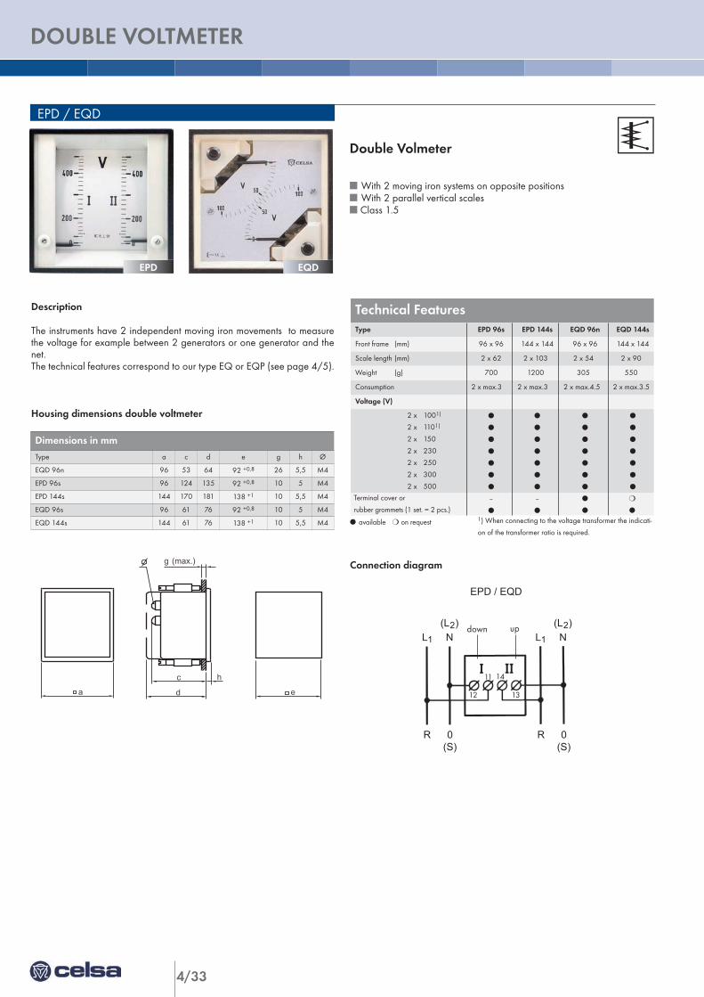
4/33
DOUBLE VOLTMETER
EPD / EQD
Description
The instruments have 2 independent moving iron movements to measurethe voltage for example between 2 generators or one generator and thenet.The technical features correspond to our type EQ or EQP (see page 4/5).
Housing dimensions double voltmeter
l available m on request 1) When connecting to the voltage transformer the indicati-
on of the transformer ratio is required.
Connection diagram
L1
(L )2N
R 0(S) (S)
0R
2(L )N1L
EPD / EQD
Double Volmeter
n With 2 moving iron systems on opposite positionsn With 2 parallel vertical scalesn Class 1.5
Dimensions in mm Type a c d e g h Ø
EQD 96n 96 53 64 92 +0,8 26 5,5 M4
EPD 96s 96 124 135 92 +0,8 10 5 M4
EPD 144s 144 170 181 138 +1 10 5,5 M4
EQD 96s 96 61 76 92 +0,8 10 5 M4
EQD 144s 144 61 76 138 +1 10 5,5 M4
Technical Features Type EPD 96s EPD 144s EQD 96n EQD 144s
Front frame (mm) 96 x 96 144 x 144 96 x 96 144 x 144
Scale length (mm) 2 x 62 2 x 10³ 2 x 54 2 x 90
Weight (g) 700 1200 305 550
Consumption 2 x max.3 2 x max.3 2 x max.4.5 2 x max.3.5
Voltage (V)
2 x 1001)
2 x 1101)
2 x 150
2 x 230
2 x 250
2 x 300
2 x 500
l
l
l
l
l
l
l
l
l
l
l
l
l
l
l
l
l
l
l
l
l
l
l
l
l
l
l
l
Terminal cover or
rubber grommets (1 set. = 2 pcs.)--
l
--
l
l
l
m
l
EPD EQD
a d
c
g (max.)
e
h
PQ / PAQ
down up
12
11
13
14
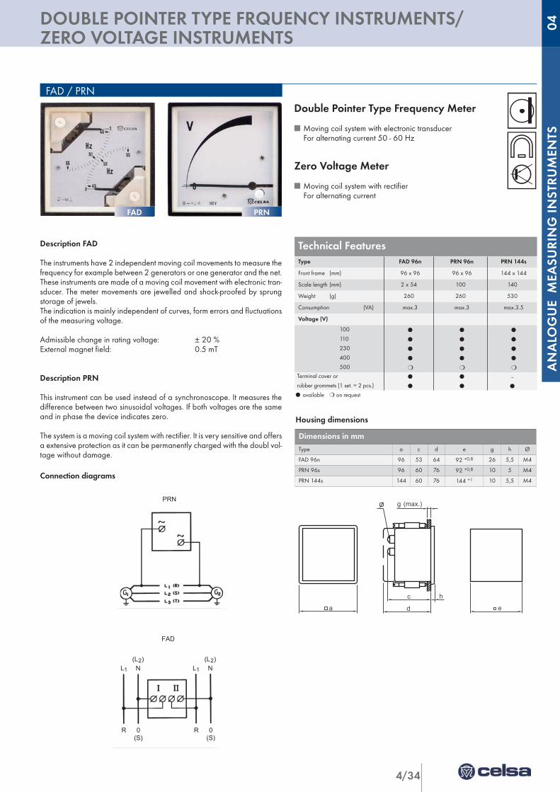
4/34
ANALO
GUE M
EASU
RIN
G IN
STRU
MEN
TS
DOUBLE POINTER TYPE FRQUENCY INSTRUMENTS/ZERO VOLTAGE INSTRUMENTS
04
FAD / PRN
Description FAD
The instruments have 2 independent moving coil movements to measure thefrequency for example between 2 generators or one generator and the net.These instruments are made of a moving coil movement with electronic tran-sducer. The meter movements are jewelled and shock-proofed by sprungstorage of jewels. The indication is mainly independent of curves, form errors and fluctuationsof the measuring voltage.
Admissible change in rating voltage: ± 20 %External magnet field: 0.5 mT
Description PRN
This instrument can be used instead of a synchronoscope. It measures thedifference between two sinusoidal voltages. If both voltages are the sameand in phase the device indicates zero.
The system is a moving coil system with rectifier. It is very sensitive and offersa extensive protection as it can be permanently charged with the doubl vol-tage without damage.
Connection diagrams
Double Pointer Type Frequency Meter
n Moving coil system with electronic transducer For alternating current 50 - 60 Hz
Zero Voltage Meter
n Moving coil system with rectifier For alternating current
l available m on request
Housing dimensions
SQ.../2, > 120 V PRN
SQ.../1 SQ.../2, < 120 V
L1
(L )2N
R 0(S) (S)
0R
2(L )N1L
FAD
Dimensions in mm Type a c d e g h Ø
FAD 96n 96 53 64 92 +0,8 26 5,5 M4
PRN 96s 96 60 76 92 +0,8 10 5 M4
PRN 144s 144 60 76 144 +1 10 5,5 M4
Technical Features Type FAD 96n PRN 96n PRN 144s
Front frame (mm) 96 x 96 96 x 96 144 x 144
Scale length (mm) 2 x 54 100 140
Weight (g) 260 260 530
Consumption (VA) max.3 max.3 max.3.5
Voltage (V)
100
110
230
400
500
l
l
l
l
m
l
l
l
l
m
l
l
l
l
m
Terminal cover or
rubber grommets (1 set. = 2 pcs.)
l
l
l
l
–
l
FAD PRN
a d
c
g (max.)
e
h
PQ / PAQ

4/35
MOVIL COIL INSTRUMENTS
PQ
Interchangeable scales All plastic executions (n-line) have interchangeable scales. This executionenables easy exchange or fit of the changing scale (not during operating).
Execution for DIN rail mounting (PQ35P)For measuring current and voltage in distribution systems with 35 mm DINrail according to DIN 50 022.
The instruments of this line are adapted by their dimensions to commoninstallation devices. The installation width of the instruemnts is 45 mm. Theycan be snapped easily on a 35 mm DIN rail.
The clamps are covered shockproof.
Execution PAQ...n with round scale 240°The movements are working for the same principle as the PQ devices. Theadvantage of these devices is the large scale length (better resolution).These instruments only measure DC current or DC voltage.These devices also have interchangeable scales.
Description
The system of our instruments is a moving coil movement with sprung toebearing which is insensitive to external magnetic fields. The movableorgans of the movements are stored in sprung jewels in order to protectthem against crushes and vibrations. These instruments only measure DCcurrent or DC voltage.
By using core magnets of high quality the moving coil instruments have aalmost linear scale course. That’s why and due to their low consumptionthey are especially suited for the application with shunts, impulse transmit-ters, thermo couples and for the connection to our electronic transducers.The instruments can be delivered for direct connection up to 100 A with abuilt-in shunt.
Overload capacity according to DIN 43780 is valid for all moving coilinstruments
Continuously 1.2 timesShort duration 10 x IN 5 s for aminstruments
2 x UN 5 s for voltinstruments
Moving Coil Instruments
n For DC voltage / DC currentn Class 1.5
Internal resistance, consumption approx. in Ohm
Measuring range PQ 35G PQ ..n PAQ ...n
µA
25
40
60 200 mV
240 mV
374 mV
600 mV
100
150
250
400
600
200 mV
200 mV
200 mV
200 mV
200 mV
400 mV
600 mV
140 mV
540 mV
540 mV
810 mV
900 mV
900 mV
mA
1
1,5
2,5
4
6
200 mV
200 mV
200 mV
200 mV
200 mV
37 mV
60 mV
60 mV
60 mV
60 mV
490 mV
425 mV
760 mV
950 mV
60 mV
4-20 200 mV 1,5 V 1,5 V
10-800 200 mV 60-70 mV 60-125 mV
A1-100 to 15A 200 mV 60-100 mV 60 mV
.../60...150mV 12 Ω 5 mA 67/200Ω/V
mV
15-40 1000 Ω/V 200 Ω/V 67 Ω/V
15-40 1000 Ω/V 200 Ω/V 67 Ω/V
60-100 1000 Ω/V 1000 Ω/V 67 Ω/V
150-600 1000 Ω/V 1000 Ω/V 200 Ω/V
750 1000 Ω/V 1000 Ω/V 200 Ω/V
V1
1,5-600
1000 Ω/V1000 Ω/V
1000 Ω/V1000 Ω/V
200 Ω/V1000 Ω/V
PQ35p PQ48n PQ72n PAQ72n PAQ96nPQ96n
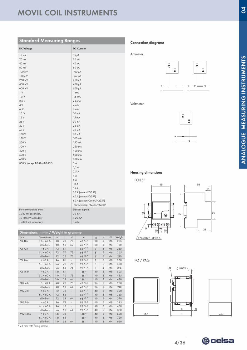
4/36
ANALO
GUE M
EASU
RIN
G IN
STRU
MEN
TS
MOVIL COIL INSTRUMENTS 04
Connection diagrams
Ammeter
Voltmeter
Housing dimensions
PQ35P
PQ / PAQ
_+
+_
_+
+_
_+
+_
1 26 mm with fixing screws
Standard Measuring RangesDC Voltage DC Current
15 mV
25 mV
40 mV
60 mV
100 mV
150 mV
250 mV
400 mV
600 mV
1 V
1,5 V
2,5 V
4 V
6 V
10 V
15 V
25 V
40 V
60 V
100 V
150 V
250 V
300 V
400 V
500 V
600 V
800 V (except PQ48n/PQ35P)
15 µA
25 µA
40 µA
60 µA
100 µA
150 µA
250µ A
400 µA
600 µA
1 mA
1,5 mA
2,5 mA
4 mA
6 mA
10 mA
15 mA
20 mA
25 mA
40 mA
60 mA
100 mA
150 mA
250 mA
400 mA
500 mA
600 mA
1 A
1,5 A
2,5 A
4 A
6 A
10 A
15 A
25 A (except PQ35P)
40 A (except PQ35P)
60 A (except PQ48n/PQ35P)
100 A (except PQ48n/PQ35P)
For connection to shunt
.../60 mV secondary
.../150 mV secondary
.../300 mV secondary
Standar signals
20 mA
4-20 mA
1 mA
Dimensions in mm / Weight in grammeType Dimensions a c d e g h Ø WeightPQ 48n < 5... 60 A 48 70 73 45 +0,6 28 5 M6 205
all others 48 55 62 45 +0,6 28 5 M4 150PQ 72n > 60 A 72 81 - 68 +0,7 81 5 M8 285
5... < 60 A 72 70 75 68 +0,7 81 5 M6 265all others 72 55 75 68 +0,7 81 5 M4 210
PQ 96n > 60 A 96 81 - 92 +0,8 81 5 M8 3505... < 60 A 96 70 75 92 +0,8 81 5 M6 330all others 96 55 75 92 +0,8 81 5 M4 275
PQ 144n > 60 A 144 81 - 138 +1 40 8 M8 5055... < 60 A 144 70 75 138 +1 40 8 M6 485all others 144 53 64 138 +1 40 8 M4 430
PAQ 48n 10... 40 A 48 70 73 45 +0,6 26 5 M6 230all others 48 53 64 45 +0,6 26 5 M4 210
PAQ 72n > 60 A 72 78 - 68 +0,7 40 5 M8 3206... < 60 A 72 68 - 68 +0,7 40 5 M6 385all others 72 53 64 68 +0,7 40 5 M4 290
PAQ 96n > 60 A 96 78 - 92 +0,8 40 5 M8 3956... < 60 A 96 68 - 92 +0,8 40 5 M6 460all others 96 53 64 92 +0,8 40 5 M4 370
PAQ 144n > 60 A 144 78 - 138 +1 40 8 M8 6806... < 60 A 144 68 - 138 +1 40 8 M6 720all others 144 53 64 138 +1 40 8 M4 650
a d
c
g (max.)
e
h
PQ / PAQ
EQ35GPQ35GFA35G
10 10 109
35
45 59
10
34
4585
EN 50022 - 35x7,5
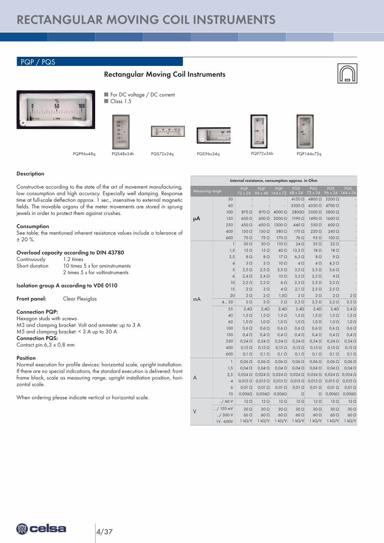
4/37
RECTANGULAR MOVING COIL INSTRUMENTS
PQP / PQS
Description
Constructive according to the state of the art of movement manufacturing,low consumption and high accuracy. Especially well damping. Responsetime at full-scale deflection approx. 1 sec., insensitive to external magneticfields. The movable organs of the meter movements are stored in sprungjewels in order to protect them against crushes.
ConsumptionSee table; the mentioned inherent resistance values include a tolerance of± 20 %.
Overload capacity according to DIN 43780Continuously 1.2 timesShort duration 10 times 5 s for aminstruments
2 times 5 s for voltinstruments
Isolation group A according to VDE 0110
Front panel: Clear Plexiglas
Connection PQP:Hexagon studs with screwsM3 and clamping bracket: Volt and ammeter up to 3 AM5 and clamping bracket: < 3 A up to 30 AConnection PQS:Contact pin 6,3 x 0,8 mm
PositionNormal execution for profile devices: horizontal scale, upright installation.If there are no special indications, the standard execution is delivered: frontframe black, scale as measuring range, upright installation position, hori-zontal scale.
When ordering please indicate vertical or horizontal scale.
Rectangular Moving Coil Instruments
n For DC voltage / DC currentn Class 1.5
Internal resistance, consumption approx. in Ohm
Measuring range PQP72 x 36
PQP96 x 48
PQP144 x 72
PQS48 x 24
PQS72 x 24
PQS96 x 24
PQS144 x 36
µA
50
60
100
150
250
400
600
-
-
870 Ω
600 Ω
450 Ω
150 Ω
75 Ω
-
-
870 Ω
600 Ω
450 Ω
150 Ω
75 Ω
-
-
4000 Ω
2000 Ω
1300 Ω
380 Ω
170 Ω
4150 Ω
3500 Ω
2800Ω
1190 Ω
440 Ω
175 Ω
76 Ω
4800 Ω
4350 Ω
3500 Ω
1490 Ω
550 Ω
220 Ω
95 Ω
5200 Ω
4700 Ω
3800 Ω
1600 Ω
600 Ω
240 Ω
100 Ω
-
-
-
-
-
-
-
mA
1
1,5
2,5
4
5
6
10
15
20
30 Ω
15 Ω
8 Ω
3 Ω
2,5 Ω
2,4 Ω
2,2 Ω
2 Ω
2 Ω
30 Ω
15 Ω
8 Ω
3 Ω
2,5 Ω
2,4 Ω
2,2 Ω
2 Ω
2 Ω
110 Ω
40 Ω
17 Ω
10 Ω
3,5 Ω
10 Ω
6 Ω
4 Ω
1,5Ω
24 Ω
13,5 Ω
6,2 Ω
4 Ω
3,5 Ω
3,3 Ω
2,3 Ω
2,1 Ω
2 Ω
35 Ω
18 Ω
8 Ω
4 Ω
3,3 Ω
2,5 Ω
2,5 Ω
2,5 Ω
2 Ω
32 Ω
18 Ω
9 Ω
4,5 Ω
3,6 Ω
4 Ω
3,5 Ω
2,5 Ω
2 Ω
-
-
-
-
-
-
-
-
2 Ω
4... 20 2 Ω 2 Ω 2 Ω 2,2 Ω 2,2 Ω 2,2 Ω 2,2 Ω
25
40
60
100
150
250
400
600
2,4Ω
1,5 Ω
1,0 Ω
0,6 Ω
0,4 Ω
0,24 Ω
0,15 Ω
0,1 Ω
2,4Ω
1,5 Ω
1,0 Ω
0,6 Ω
0,4 Ω
0,24 Ω
0,15 Ω
0,1 Ω
2,4Ω
1,5 Ω
1,0 Ω
0,6 Ω
0,4 Ω
0,24 Ω
0,15 Ω
0,1 Ω
2,4Ω
1,5 Ω
1,0 Ω
0,6 Ω
0,4 Ω
0,24 Ω
0,15 Ω
0,1 Ω
2,4Ω
1,5 Ω
1,0 Ω
0,6 Ω
0,4 Ω
0,24 Ω
0,15 Ω
0,1 Ω
2,4Ω
1,5 Ω
1,0 Ω
0,6 Ω
0,4 Ω
0,24 Ω
0,15 Ω
0,1 Ω
2,4 Ω
1,5 Ω
1,0 Ω
0,6 Ω
0,4 Ω
0,24 Ω
0,15 Ω
0,1 Ω
A
1
1,5
2,5
4
6
10
0,06 Ω
0,04 Ω
0,024 Ω
0,015 Ω
0,01 Ω
0,006Ω
0,06 Ω
0,04 Ω
0,024 Ω
0,015 Ω
0,01 Ω
0,006Ω
0,06 Ω
0,04 Ω
0,024 Ω
0,015 Ω
0,01 Ω
0,006Ω
0,06 Ω
0,04 Ω
0,024 Ω
0,015 Ω
0,01 Ω
Ω
0,06 Ω
0,04 Ω
0,024 Ω
0,015 Ω
0,01 Ω
Ω
0,06 Ω
0,04 Ω
0,024 Ω
0,015 Ω
0,01 Ω
0,006Ω
0,06 Ω
0,04 Ω
0,024 Ω
0,015 Ω
0,01 Ω
0,006Ω
V
.../ 60 V 12 Ω 12 Ω 12 Ω 12 Ω 12 Ω 12 Ω 12 Ω
.../ 150 mV
.../ 300 V
1V - 600V
30 Ω60 Ω
1 kΩ/V
30 Ω60 Ω
1 kΩ/V
30 Ω60 Ω
1 kΩ/V
30 Ω60 Ω
1 kΩ/V
30 Ω60 Ω
1 kΩ/V
30 Ω60 Ω
1 kΩ/V
30 Ω60 Ω
1 kΩ/V
PQS48x24h PQS72x24q PQS96x24q PQP72x36h PQP144x72qPQP96x48q
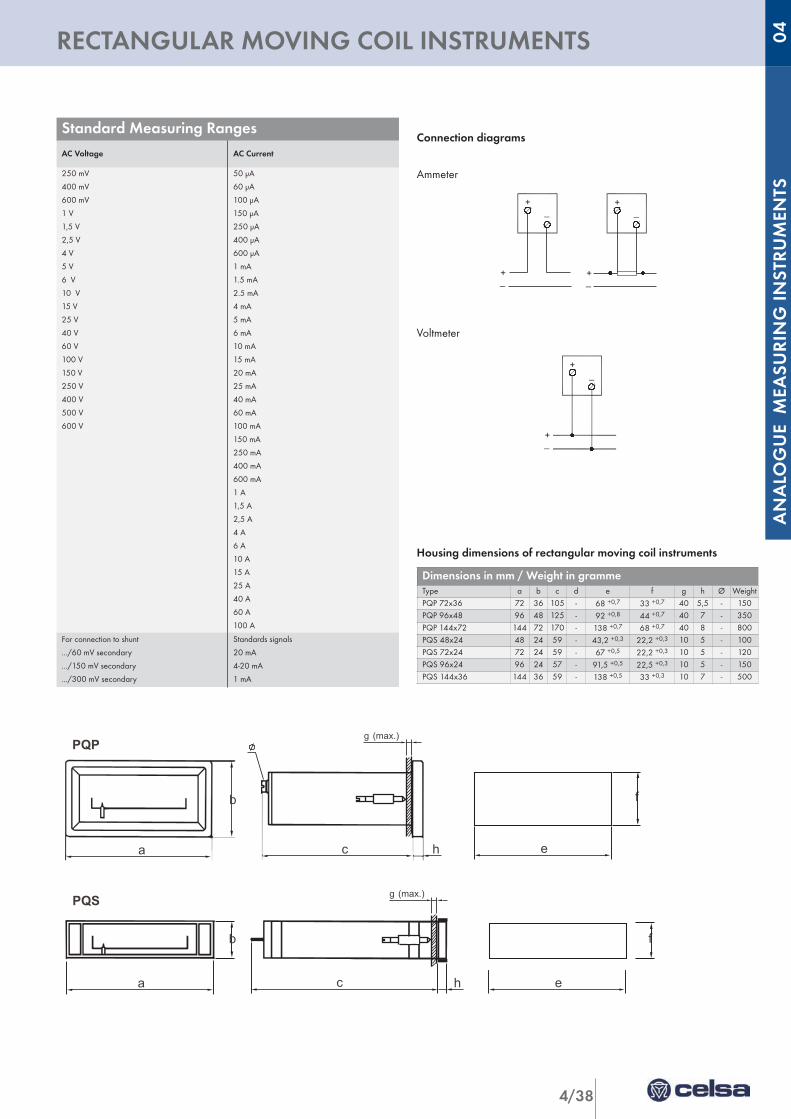
4/38
ANALO
GUE M
EASU
RIN
G IN
STRU
MEN
TS
RECTANGULAR MOVING COIL INSTRUMENTS 04
Connection diagrams
Ammeter
Voltmeter
Housing dimensions of rectangular moving coil instruments
e
f
a c h
b
PQS (max.)g
b
ha c e
f
PQP(max.)g
Standard Measuring RangesAC Voltage AC Current
250 mV
400 mV
600 mV
1 V
1,5 V
2,5 V
4 V
5 V
6 V
10 V
15 V
25 V
40 V
60 V
100 V
150 V
250 V
400 V
500 V
600 V
50 µA
60 µA
100 µA
150 µA
250 µA
400 µA
600 µA
1 mA
1.5 mA
2.5 mA
4 mA
5 mA
6 mA
10 mA
15 mA
20 mA
25 mA
40 mA
60 mA
100 mA
150 mA
250 mA
400 mA
600 mA
1 A
1,5 A
2,5 A
4 A
6 A
10 A
15 A
25 A
40 A
60 A
100 A
For connection to shunt
.../60 mV secondary
.../150 mV secondary
.../300 mV secondary
Standards signals
20 mA
4-20 mA
1 mA
Dimensions in mm / Weight in grammeType a b c d e f g h Ø WeightPQP 72x36 72 36 105 - 68 +0,7 33 +0,7 40 5,5 - 150PQP 96x48 96 48 125 - 92 +0,8 44 +0,7 40 7 - 350PQP 144x72 144 72 170 - 138 +0,7 68 +0,7 40 8 - 800PQS 48x24 48 24 59 - 43,2 +0,3 22,2 +0,3 10 5 - 100PQS 72x24 72 24 59 - 67 +0,5 22,2 +0,3 10 5 - 120PQS 96x24 96 24 57 - 91,5 +0,5 22,5 +0,3 10 5 - 150PQS 144x36 144 36 59 - 138 +0,5 33 +0,3 10 7 - 500
_+
+_
_+
+_
_+
+_
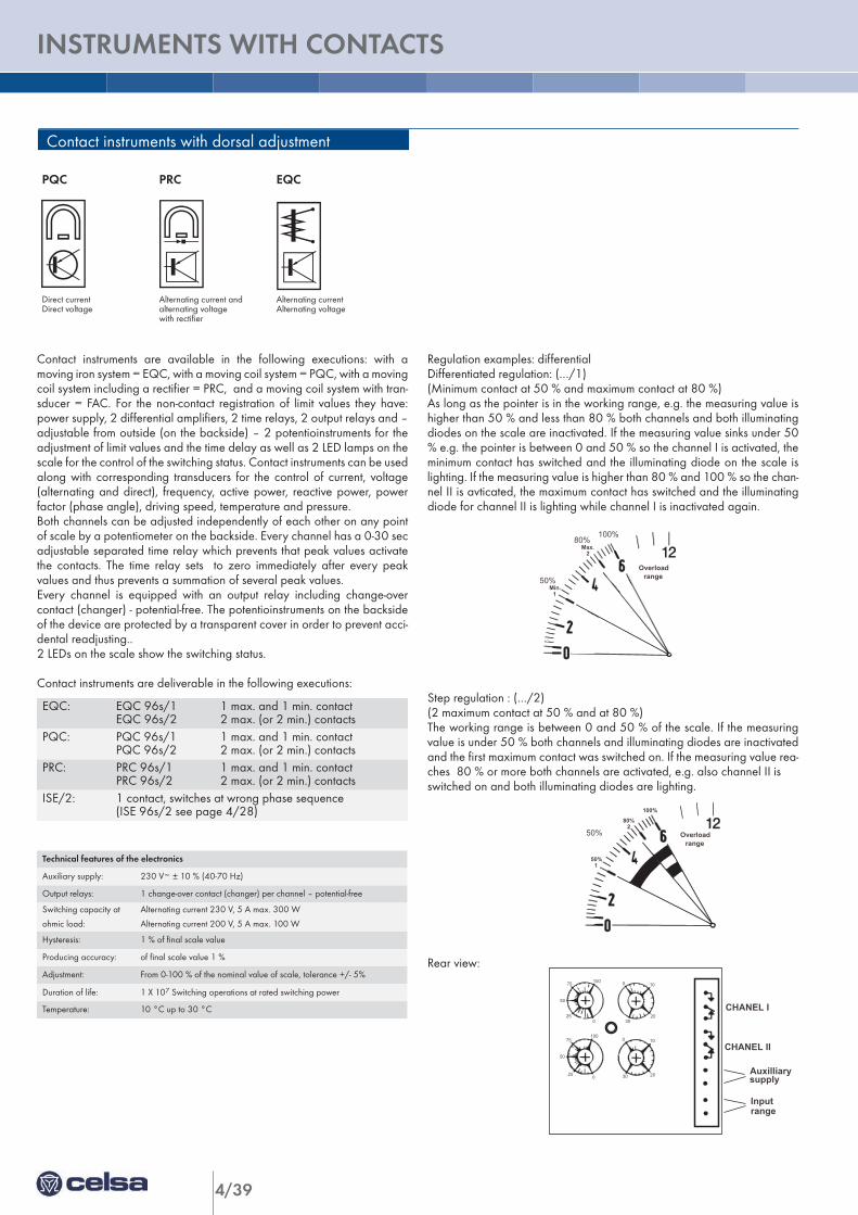
4/39
INSTRUMENTS WITH CONTACTS
Regulation examples: differentialDifferentiated regulation: (…/1)(Minimum contact at 50 % and maximum contact at 80 %)As long as the pointer is in the working range, e.g. the measuring value ishigher than 50 % and less than 80 % both channels and both illuminatingdiodes on the scale are inactivated. If the measuring value sinks under 50% e.g. the pointer is between 0 and 50 % so the channel I is activated, theminimum contact has switched and the illuminating diode on the scale islighting. If the measuring value is higher than 80 % and 100 % so the chan-nel II is avticated, the maximum contact has switched and the illuminatingdiode for channel II is lighting while channel I is inactivated again.
Step regulation : (…/2)(2 maximum contact at 50 % and at 80 %)The working range is between 0 and 50 % of the scale. If the measuringvalue is under 50 % both channels and illuminating diodes are inactivatedand the first maximum contact was switched on. If the measuring value rea-ches 80 % or more both channels are activated, e.g. also channel II isswitched on and both illuminating diodes are lighting.
Rear view:
Contact instruments with dorsal adjustment
PQC
Direct currentDirect voltage
Alternating current andalternating voltagewith rectifier
Alternating currentAlternating voltage
PRC EQC
Min.1
2Max.
rangeOverload
50%
80%100%
100
0
75
50
25
0
30
10
20
10075
50
25 0
0
30
10
20 Auxilliary
CHANEL I
CHANEL II
Input
supply
range
Contact instruments are available in the following executions: with amoving iron system = EQC, with a moving coil system = PQC, with a movingcoil system including a rectifier = PRC, and a moving coil system with tran-sducer = FAC. For the non-contact registration of limit values they have:power supply, 2 differential amplifiers, 2 time relays, 2 output relays and –adjustable from outside (on the backside) – 2 potentioinstruments for theadjustment of limit values and the time delay as well as 2 LED lamps on thescale for the control of the switching status. Contact instruments can be usedalong with corresponding transducers for the control of current, voltage(alternating and direct), frequency, active power, reactive power, powerfactor (phase angle), driving speed, temperature and pressure.Both channels can be adjusted independently of each other on any pointof scale by a potentiometer on the backside. Every channel has a 0-30 secadjustable separated time relay which prevents that peak values activatethe contacts. The time relay sets to zero immediately after every peakvalues and thus prevents a summation of several peak values. Every channel is equipped with an output relay including change-overcontact (changer) - potential-free. The potentioinstruments on the backsideof the device are protected by a transparent cover in order to prevent acci-dental readjusting..2 LEDs on the scale show the switching status.
Contact instruments are deliverable in the following executions:
50%1
80%2
100%
Overloadrange
50%
EQC: EQC 96s/1 1 max. and 1 min. contactEQC 96s/2 2 max. (or 2 min.) contacts
PQC: PQC 96s/1 1 max. and 1 min. contactPQC 96s/2 2 max. (or 2 min.) contacts
PRC: PRC 96s/1 1 max. and 1 min. contactPRC 96s/2 2 max. (or 2 min.) contacts
ISE/2: 1 contact, switches at wrong phase sequence(ISE 96s/2 see page 4/28)
Technical features of the electronics
Auxiliary supply: 230 V~ ± 10 % (40-70 Hz)
Output relays: 1 change-over contact (changer) per channel – potential-free
Switching capacity at Alternating current 230 V, 5 A max. 300 W
ohmic load: Alternating current 200 V, 5 A max. 100 W
Hysteresis: 1 % of final scale value
Producing accuracy: of final scale value 1 %
Adjustment: From 0-100 % of the nominal value of scale, tolerance +/- 5%
Duration of life: 1 X 10⁷ Switching operations at rated switching power
Temperature: 10 °C up to 30 °C
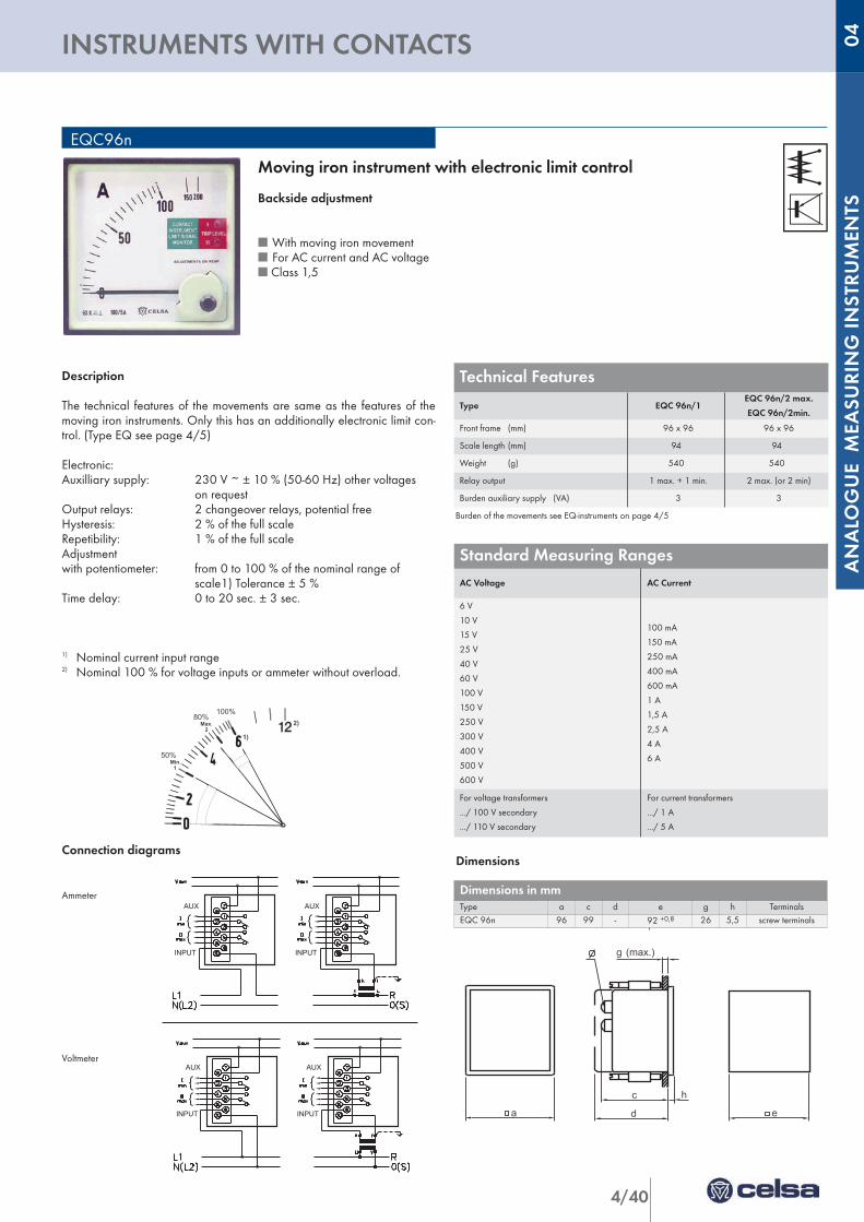
4/40
ANALO
GUE M
EASU
RIN
G IN
STRU
MEN
TS
INSTRUMENTS WITH CONTACTS 04
Description
The technical features of the movements are same as the features of themoving iron instruments. Only this has an additionally electronic limit con-trol. (Type EQ see page 4/5)
Electronic:Auxilliary supply: 230 V ~ ± 10 % (50-60 Hz) other voltages
on requestOutput relays: 2 changeover relays, potential freeHysteresis: 2 % of the full scaleRepetibility: 1 % of the full scaleAdjustment with potentiometer: from 0 to 100 % of the nominal range of
scale1) Tolerance ± 5 %Time delay: 0 to 20 sec. ± 3 sec.
1) Nominal current input range2) Nominal 100 % for voltage inputs or ammeter without overload.
Connection diagrams
Ammeter
Voltmeter
AUX
INPUT INPUT
AUX
AUX
INPUT INPUT
AUX
Min.1
2Max.
50%
80%100%
1)
2)
EQC96n
Moving iron instrument with electronic limit control
Backside adjustment
n With moving iron movementn For AC current and AC voltagen Class 1,5
Dimensions
Dimensions in mmType a c d e g h TerminalsEQC 96n 96 99 - 92 +0,8 26 5,5 screw terminals
Standard Measuring RangesAC Voltage AC Current
6 V
10 V
15 V
25 V
40 V
60 V
100 V
150 V
250 V
300 V
400 V
500 V
600 V
100 mA
150 mA
250 mA
400 mA
600 mA
1 A
1,5 A
2,5 A
4 A
6 A
For voltage transformers
.../ 100 V secondary
.../ 110 V secondary
For current transformers
.../ 1 A
.../ 5 A
Technical Features
Type EQC 96n/1EQC 96n/2 max.
EQC 96n/2min.
Front frame (mm) 96 x 96 96 x 96
Scale length (mm) 94 94
Weight (g) 540 540
Relay output 1 max. + 1 min. 2 max. (or 2 min)
Burden auxiliary supply (VA) 3 3
Burden of the movements see EQ-instruments on page 4/5
a d
c
g (max.)
e
h
PQ / PAQ
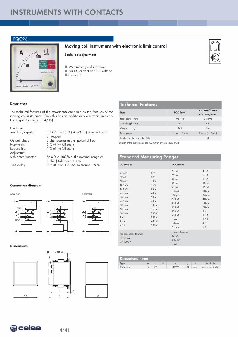
4/41
INSTRUMENTS WITH CONTACTS
Description
The technical features of the movements are same as the features of themoving coil instruments. Only this has an additionally electronic limit con-trol. (Type PQ see page 4/35)
Electronic:Auxilliary supply: 230 V ~ ± 10 % (50-60 Hz) other voltages
on requestOutput relays: 2 changeover relays, potential freeHysteresis: 2 % of the full scaleRepetibility: 1 % of the full scaleAdjustment with potentiometer: from 0 to 100 % of the nominal range of
scale1) Tolerance ± 5 %Time delay: 0 to 30 sec. ± 3 sec. Tolerance ± 5 %
Connection diagrams
Ammeter Voltmeter
Dimensions
AUX
INPUT
PQC96n
Moving coil instrument with electronic limit control
Backside adjustment
n With moving coil movementn For DC current and DC voltagen Class 1,5
Dimensions in mmType a c d e g h TerminalsPQC 96n 96 99 - 92 +0,8 26 5,5 screw terminals
Standard Measuring RangesDC Voltage DC Current
40 mV 5 V
50 mV 6 V
60 mV 10 V
100 mV 15 V
150 mV 25 V
250 mV 40 V
300 mV 50 V
400 mV 60 V
500 mV 100 V
600 mV 150 V
800 mV 250 V
1 V 300 V
1,5 V 400 V
2,5 V 500 V
20 µA 4 mA
25 µA 5 mA
40 µA 6 mA
50 µA 10 mA
60 µA 15 mA
100 µA 20 mA
150 µA 25 mA
200 µA 40 mA
300 µA 50 mA
400 µA 60 mA
500 µA 1 A
600 µA 1,5 A
1 mA 2,5 A
1,5 mA 4 A
2,5 mA 5 A
For connection to shunt
.../ 60 mV
.../ 150 mV
Standard signals
20 mA
4-20 mA
1 mA
Technical Features
Type PQC 96n/1PQC 96n/2 max.
PQC 96n/2min.
Front frame (mm) 96 x 96 96 x 96
Scale length (mm) 94 94
Weight (g) 540 540
Relay output 1 max. + 1 min. 2 max. (or 2 min)
Burden auxiliary supply (VA) 3 3
Burden of the movements see PQ-instruments on page 4/35
a d
c
g (max.)
e
h
PQ / PAQ

4/42
ANALO
GUE M
EASU
RIN
G IN
STRU
MEN
TS
NOTES 04