pci express to 6gb/s serial attached scsi (sas) host bus ... lsi manual.pdf · pci express to 6gb/s...
TRANSCRIPT
PCI Express® to 6Gb/s Serial Attached SCSI (SAS)Host Bus Adapters
User Guide
May 2013
DB15-000556-12
LSI, the LSI & Design logo, and Fusion-MPT are registered trademarks or trademarks of LSI Corporation or its subsidiaries. All other brand and product names may be trademarks of their respectivecompanies.
PCI Express and PCIe are registered trademarks of PCI-SIG Corporation. Windows is a registered trademark of Microsoft Corporation. Linux is the registered trademark of Linus Torvalds in the U.S. andother countries. Oracle is a registered trademark of Oracle and/or its affiliates. Red Hat is a registered trademarks of Red Hat, Inc. SUSE and SLES are registered trademarks of Novell, Inc. VMware is aregistered trademark of VMware, Inc. FreeBSD is a registered trademark of The FreeBSD Foundation non-profit corporation.
LSI Corporation reserves the right to make changes to the product(s) or information disclosed herein at any time without notice. LSI Corporation does not assume any responsibility or liability arising out ofthe application or use of any product or service described herein, except as expressly agreed to in writing by LSI Corporation; nor does the purchase, lease, or use of a product or service from LSI Corporationconvey a license under any patent rights, copyrights, trademark rights, or any other of the intellectual property rights of LSI Corporation or of third parties. LSI products are not intended for use in life-supportappliances, devices, or systems. Use of any LSI product in such applications without written consent of the appropriate LSI officer is prohibited.
Corporate Headquarters Email WebsiteMilpitas, CA [email protected] www.lsi.com800-372-2447
Document Number: DB15-000556-12Copyright © 2012 LSI CorporationAll Rights Reserved
PCI Express to 6Gb/s Serial Attached SCSI (SAS) Host Bus Adapters User GuideMay 2013
Revision History
Version and Date Description of Changes
May 2013 Updated the Maximum Power Requirements table and Section 3.2.2, Thermal and Atmospheric Limits.
October 2012 Added information for the LSISAS9208-8i and LSISAS 9218-8i host adapter board. Updated the Maximum Power Requirements table.
July 2012 Updated the Maximum Power Requirements table.
June 2012 Prepared the document for general distribution.
May 2012 Updated the Maximum Power Requirements table.
January 2012 Added information for the LSISAS9206-16e host adapter board. Updated the Maximum Power Requirements table.Added the HBA Feature Matrix Appendix.Renamed the LSISAS9215-8i to the LSISAS9217-8i host bus adapter board. Renamed the LSISAS9215-4i4e to the LSISAS9207-4i4e host bus adapter board.
May 2011 Added information for the LSISAS9205-8e, LSISAS9215-4i4e, and LSISAS9215-8i host adapter boards. Updated document template.
September 2010 Added information for the LSISAS9202-16e host adapter board.
April 2010 Added information for the LSISAS9201-16i, and LSISAS9201-16e host adapter boards.
March 2010 Updated Figure 2, LSISAS9200-8e Board Layout, on page 11, Figure 3, LSISAS9210-8i Board Layout, on page 12, Figure 5, LSISAS9211-8i Board Layout, on page 15, Figure 4, LSISAS9211-4i Board Layout, on page 14, Figure 6, LSISAS9212-4i4e Board Layout, on page 17, and Figure 7, LSISAS9200-16e Board Layout, on page 19.
October 2009 Added information for the LSISAS9212-4i4e and the LSISAS9200-16e host adapter boards.
July 2009 Initial release of this document.
LSI Corporation- 3 -
Table of Contents
PCI Express to 6Gb/s Serial Attached SCSI (SAS) Host Bus Adapters User GuideMay 2013
Table of Contents
Chapter 1: Introduction . . . . . . . . . . . . . . . . . . . . . . . . . . . . . . . . . . . . . . . . . . . . . . . . . . . . . . . . . . . . . . . . . . . . . . . . . . . . . . . . . . . . . . . . . . . . . . . . . . . . . . . . . 4
1.1 Overview . . . . . . . . . . . . . . . . . . . . . . . . . . . . . . . . . . . . . . . . . . . . . . . . . . . . . . . . . . . . . . . . . . . . . . . . . . . . . . . . . . . . . . . . . . . . . . . . . . . . . . . . . . . . . . . . . . . . . . . . . . . . 41.2 SAS Features . . . . . . . . . . . . . . . . . . . . . . . . . . . . . . . . . . . . . . . . . . . . . . . . . . . . . . . . . . . . . . . . . . . . . . . . . . . . . . . . . . . . . . . . . . . . . . . . . . . . . . . . . . . . . . . . . . . . . . . . . 51.3 PCI Express Host Interface Features . . . . . . . . . . . . . . . . . . . . . . . . . . . . . . . . . . . . . . . . . . . . . . . . . . . . . . . . . . . . . . . . . . . . . . . . . . . . . . . . . . . . . . . . . . . . . . . . . . . 61.4 Software . . . . . . . . . . . . . . . . . . . . . . . . . . . . . . . . . . . . . . . . . . . . . . . . . . . . . . . . . . . . . . . . . . . . . . . . . . . . . . . . . . . . . . . . . . . . . . . . . . . . . . . . . . . . . . . . . . . . . . . . . . . . . 7
Chapter 2: Hardware Installation. . . . . . . . . . . . . . . . . . . . . . . . . . . . . . . . . . . . . . . . . . . . . . . . . . . . . . . . . . . . . . . . . . . . . . . . . . . . . . . . . . . . . . . . . . . . . . . . . 8
2.1 Installation Instructions . . . . . . . . . . . . . . . . . . . . . . . . . . . . . . . . . . . . . . . . . . . . . . . . . . . . . . . . . . . . . . . . . . . . . . . . . . . . . . . . . . . . . . . . . . . . . . . . . . . . . . . . . . . . . .8
Chapter 3: Host Bus Adapter Characteristics . . . . . . . . . . . . . . . . . . . . . . . . . . . . . . . . . . . . . . . . . . . . . . . . . . . . . . . . . . . . . . . . . . . . . . . . . . . . . . . . . . . . . 10
3.1 Characteristics of the LSI 6Gb/s HBAs . . . . . . . . . . . . . . . . . . . . . . . . . . . . . . . . . . . . . . . . . . . . . . . . . . . . . . . . . . . . . . . . . . . . . . . . . . . . . . . . . . . . . . . . . . . . . . . .103.1.1 LSISAS9200-8e HBA Characteristics. . . . . . . . . . . . . . . . . . . . . . . . . . . . . . . . . . . . . . . . . . . . . . . . . . . . . . . . . . . . . . . . . . . . . . . . . . . . . . . . . . . . . . . . . . . 103.1.2 LSISAS9210-8i HBA Characteristics . . . . . . . . . . . . . . . . . . . . . . . . . . . . . . . . . . . . . . . . . . . . . . . . . . . . . . . . . . . . . . . . . . . . . . . . . . . . . . . . . . . . . . . . . . . 113.1.3 LSISAS9211-4i HBA Characteristics . . . . . . . . . . . . . . . . . . . . . . . . . . . . . . . . . . . . . . . . . . . . . . . . . . . . . . . . . . . . . . . . . . . . . . . . . . . . . . . . . . . . . . . . . . . 133.1.4 LSISAS9211-8i HBA Characteristics . . . . . . . . . . . . . . . . . . . . . . . . . . . . . . . . . . . . . . . . . . . . . . . . . . . . . . . . . . . . . . . . . . . . . . . . . . . . . . . . . . . . . . . . . . . 143.1.5 LSISAS9212-4i4e HBA Characteristics . . . . . . . . . . . . . . . . . . . . . . . . . . . . . . . . . . . . . . . . . . . . . . . . . . . . . . . . . . . . . . . . . . . . . . . . . . . . . . . . . . . . . . . . . 163.1.6 LSISAS9200-16e HBA Characteristics . . . . . . . . . . . . . . . . . . . . . . . . . . . . . . . . . . . . . . . . . . . . . . . . . . . . . . . . . . . . . . . . . . . . . . . . . . . . . . . . . . . . . . . . . 173.1.7 LSISAS9201-16e HBA Characteristics . . . . . . . . . . . . . . . . . . . . . . . . . . . . . . . . . . . . . . . . . . . . . . . . . . . . . . . . . . . . . . . . . . . . . . . . . . . . . . . . . . . . . . . . . 193.1.8 LSISAS9201-16i HBA Characteristics . . . . . . . . . . . . . . . . . . . . . . . . . . . . . . . . . . . . . . . . . . . . . . . . . . . . . . . . . . . . . . . . . . . . . . . . . . . . . . . . . . . . . . . . . . 213.1.9 LSISAS9202-16e HBA Characteristics . . . . . . . . . . . . . . . . . . . . . . . . . . . . . . . . . . . . . . . . . . . . . . . . . . . . . . . . . . . . . . . . . . . . . . . . . . . . . . . . . . . . . . . . . 233.1.10 LSISAS9205-8e HBA Characteristics . . . . . . . . . . . . . . . . . . . . . . . . . . . . . . . . . . . . . . . . . . . . . . . . . . . . . . . . . . . . . . . . . . . . . . . . . . . . . . . . . . . . . . . . . 243.1.11 LSISAS9207-8e HBA Characteristics . . . . . . . . . . . . . . . . . . . . . . . . . . . . . . . . . . . . . . . . . . . . . . . . . . . . . . . . . . . . . . . . . . . . . . . . . . . . . . . . . . . . . . . . . 263.1.12 LSISAS9207-8i HBA Characteristics . . . . . . . . . . . . . . . . . . . . . . . . . . . . . . . . . . . . . . . . . . . . . . . . . . . . . . . . . . . . . . . . . . . . . . . . . . . . . . . . . . . . . . . . . . 273.1.13 LSISAS9208-8i HBA Characteristics . . . . . . . . . . . . . . . . . . . . . . . . . . . . . . . . . . . . . . . . . . . . . . . . . . . . . . . . . . . . . . . . . . . . . . . . . . . . . . . . . . . . . . . . . . 283.1.14 LSISAS9207-4i4e HBA Characteristics. . . . . . . . . . . . . . . . . . . . . . . . . . . . . . . . . . . . . . . . . . . . . . . . . . . . . . . . . . . . . . . . . . . . . . . . . . . . . . . . . . . . . . . . 293.1.15 LSISAS9217-8i HBA Characteristics . . . . . . . . . . . . . . . . . . . . . . . . . . . . . . . . . . . . . . . . . . . . . . . . . . . . . . . . . . . . . . . . . . . . . . . . . . . . . . . . . . . . . . . . . . 313.1.16 LSISAS9218-8i HBA Characteristics . . . . . . . . . . . . . . . . . . . . . . . . . . . . . . . . . . . . . . . . . . . . . . . . . . . . . . . . . . . . . . . . . . . . . . . . . . . . . . . . . . . . . . . . . . 323.1.17 LSISAS9217-4i4e HBA Characteristics. . . . . . . . . . . . . . . . . . . . . . . . . . . . . . . . . . . . . . . . . . . . . . . . . . . . . . . . . . . . . . . . . . . . . . . . . . . . . . . . . . . . . . . . 333.1.18 LSISAS9206-16e HBA Characteristics . . . . . . . . . . . . . . . . . . . . . . . . . . . . . . . . . . . . . . . . . . . . . . . . . . . . . . . . . . . . . . . . . . . . . . . . . . . . . . . . . . . . . . . . 34
3.2 Environmental Specifications . . . . . . . . . . . . . . . . . . . . . . . . . . . . . . . . . . . . . . . . . . . . . . . . . . . . . . . . . . . . . . . . . . . . . . . . . . . . . . . . . . . . . . . . . . . . . . . . . . . . . . . .363.2.1 Power Requirements . . . . . . . . . . . . . . . . . . . . . . . . . . . . . . . . . . . . . . . . . . . . . . . . . . . . . . . . . . . . . . . . . . . . . . . . . . . . . . . . . . . . . . . . . . . . . . . . . . . . . . . . 363.2.2 Thermal and Atmospheric Limits . . . . . . . . . . . . . . . . . . . . . . . . . . . . . . . . . . . . . . . . . . . . . . . . . . . . . . . . . . . . . . . . . . . . . . . . . . . . . . . . . . . . . . . . . . . . . 37
3.3 LSI PCIe-to-SAS HBA Certifications and Safety Characteristics . . . . . . . . . . . . . . . . . . . . . . . . . . . . . . . . . . . . . . . . . . . . . . . . . . . . . . . . . . . . . . . . . . . . . . . . .37
Appendix A: HBA Feature Matrix. . . . . . . . . . . . . . . . . . . . . . . . . . . . . . . . . . . . . . . . . . . . . . . . . . . . . . . . . . . . . . . . . . . . . . . . . . . . . . . . . . . . . . . . . . . . . . . . 38
LSI Corporation- 4 -
PCI Express to 6Gb/s Serial Attached SCSI (SAS) Host Bus Adapters User GuideMay 2013
IntroductionOverview
Chapter 1: Introduction
1.1 Overview
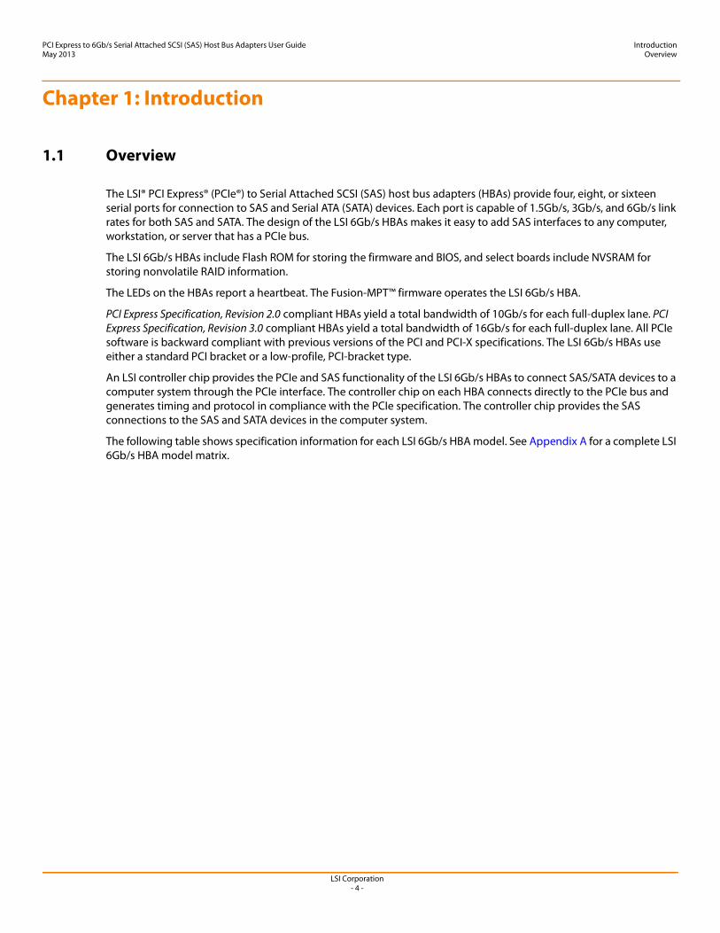
The LSI® PCI Express® (PCIe®) to Serial Attached SCSI (SAS) host bus adapters (HBAs) provide four, eight, or sixteen serial ports for connection to SAS and Serial ATA (SATA) devices. Each port is capable of 1.5Gb/s, 3Gb/s, and 6Gb/s link rates for both SAS and SATA. The design of the LSI 6Gb/s HBAs makes it easy to add SAS interfaces to any computer, workstation, or server that has a PCIe bus.
The LSI 6Gb/s HBAs include Flash ROM for storing the firmware and BIOS, and select boards include NVSRAM for storing nonvolatile RAID information.
The LEDs on the HBAs report a heartbeat. The Fusion-MPT™ firmware operates the LSI 6Gb/s HBA.
PCI Express Specification, Revision 2.0 compliant HBAs yield a total bandwidth of 10Gb/s for each full-duplex lane. PCI Express Specification, Revision 3.0 compliant HBAs yield a total bandwidth of 16Gb/s for each full-duplex lane. All PCIe software is backward compliant with previous versions of the PCI and PCI-X specifications. The LSI 6Gb/s HBAs use either a standard PCI bracket or a low-profile, PCI-bracket type.
An LSI controller chip provides the PCIe and SAS functionality of the LSI 6Gb/s HBAs to connect SAS/SATA devices to a computer system through the PCIe interface. The controller chip on each HBA connects directly to the PCIe bus and generates timing and protocol in compliance with the PCIe specification. The controller chip provides the SAS connections to the SAS and SATA devices in the computer system.
The following table shows specification information for each LSI 6Gb/s HBA model. See Appendix A for a complete LSI 6Gb/s HBA model matrix.
LSI Corporation- 5 -
PCI Express to 6Gb/s Serial Attached SCSI (SAS) Host Bus Adapters User GuideMay 2013
IntroductionSAS Features
1.2 SAS Features
This section lists the SAS features of the LSI 6Gb/s SAS HBAs:
Supports serial SCSI protocol (SSP), serial ATA tunneling protocol (STP), and serial management protocol (SMP), as defined in the Serial Attached SCSI (SAS) Specification, version 2.0.
Supports SATA, as defined in the Serial ATA Specification, version 3.0. Provides configurable drive spin-up sequencing on a per-phy basis. Simplifies cabling with a point-to-point, serial architecture. Provides smaller and thinner cables that promote unrestricted airflow. Provides a serial, point-to-point, enterprise-level storage interface. Transfers data using SCSI information units.
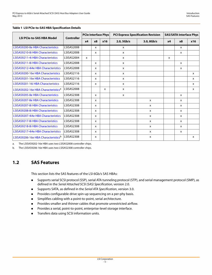
Table 1 LSI PCIe-to-SAS HBA Specification Details
LSI PCIe-to-SAS HBA Model ControllerPCIe Interface Phys PCI Express Specification Revision SAS/SATA Interface Phys
x4 x8 x16 2.0, 5Gb/s 3.0, 8Gb/s x4 x8 x16
LSISAS9200-8e HBA Characteristics LSISAS2008 x x x
LSISAS9210-8i HBA Characteristics LSISAS2008 x x x
LSISAS9211-4i HBA Characteristics LSISAS2004 x x x
LSISAS9211-8i HBA Characteristics LSISAS2008 x x x
LSISAS9212-4i4e HBA Characteristics LSISAS2008 x x x
LSISAS9200-16e HBA Characteristics LSISAS2116 x x x
LSISAS9201-16e HBA Characteristics LSISAS2116 x x x
LSISAS9201-16i HBA Characteristics LSISAS2116 x x x
LSISAS9202-16e HBA Characteristicsa LSISAS2008 x x x
LSISAS9205-8e HBA Characteristics LSISAS2308 x x x
LSISAS9207-8e HBA Characteristics LSISAS2308 x x x
LSISAS9207-8i HBA Characteristics LSISAS2308 x x x
LSISAS9208-8i HBA Characteristics LSISAS2308 x x x
LSISAS9207-4i4e HBA Characteristics LSISAS2308 x x x
LSISAS9217-8i HBA Characteristics LSISAS2308 x x x
LSISAS9218-8i HBA Characteristics LSISAS2308 x x x
LSISAS9217-4i4e HBA Characteristics LSISAS2308 x x x
LSISAS9206-16e HBA Characteristicsb LSISAS2308 x x x
a. The LSISAS9202-16e HBA uses two LSISAS2008 controller chips.
b. The LSISAS9206-16e HBA uses two LSISAS2308 controller chips.
LSI Corporation- 6 -
PCI Express to 6Gb/s Serial Attached SCSI (SAS) Host Bus Adapters User GuideMay 2013
IntroductionPCI Express Host Interface Features
Provides compatibility with SATA target devices. Supports narrow ports and wide ports, as described in the following table.
1.3 PCI Express Host Interface Features
This section lists the PCIe host interface features of the LSI 6Gb/s HBAs:
A single-phy (one lane) link transfer rate up to 8Gb/s in each direction. Link widths of x16, x8, x4, and x1. Automatic downshift. The LSISAS9202-16e HBA automatically downshifts to a x8-link width if plugged into a x16
connector that is wired as a x8 connector. Other HBA models automatically downshift to a x4-link if plugged into a x8 connector that is wired as a x4 connector.
A scalable interface.
Serial, point-to-point interconnections between devices.— Reduces the electrical load of the connection— Enables higher transmission and reception frequencies
Lane reversal and polarity inversion. PCIe hot plug. Power management.
— Supports PCI Power Management 1.2— Supports active-state power management (ASPM), including the L0, L0s, and L1 states, by placing links in a
power-saving mode when there is no link activity A replay buffer that preserves a copy of the data for retransmission in case a cyclic redundancy check (CRC)
error occurs. PCIe advanced error-reporting capabilities. Packetized and layered architecture. High bandwidth per pin with low overhead and low latency.
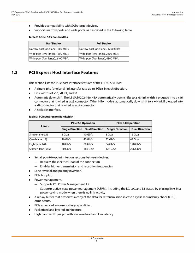
Table 2 6Gb/s SAS Bandwidths
Half Duplex Full Duplex
Narrow port (one lane), 600 MB/s Narrow port (one lane), 1200 MB/s
Wide port (two lanes), 1200 MB/s Wide port (two lanes), 2400 MB/s
Wide port (four lanes), 2400 MB/s Wide port (four lanes), 4800 MB/s
Table 3 PCIe Aggregate Bandwidth
LanesPCIe 2.0 Operation PCIe 3.0 Operation
Single Direction Dual Direction Single Direction Dual Direction
Single-lane (x1) 5 Gb/s 10 Gb/s 8 Gb/s 16 Gb/s
Quad-lane (x4) 20 Gb/s 40 Gb/s 32 Gb/s 64 Gb/s
Eight-lane (x8) 40 Gb/s 80 Gb/s 64 Gb/s 128 Gb/s
Sixteen-lane (x16) 80 Gb/s 160 Gb/s 128 Gb/s 256 Gb/s
LSI Corporation- 7 -
PCI Express to 6Gb/s Serial Attached SCSI (SAS) Host Bus Adapters User GuideMay 2013
IntroductionSoftware
Software compatibility with PCI and PCI-X software.— Leverages existing PCI device drivers— Supports the memory, I/O, and configuration address spaces— Supports memory read/write transactions, I/O read/write transactions, and configuration read/write
transactions 4 KB of PCI configuration address space per device. Posted transactions and nonposted transactions. Quality-of-service (QOS) link configuration and arbitration policies. Traffic Class 0 and one virtual channel. Message-signaled interrupts (both MSI and MSI-X), as well as INTx interrupt signaling for legacy PCI support. End-to-end CRC (ECRC) and advanced error reporting.
1.4 Software
The LSI 6Gb/s HBAs support all major operating systems: Windows®, Linux® Red Hat®, SUSE® Linux Enterprise Server (SLES®), Solaris, VMware®, and FreeBSD®. Refer to http://www.lsi.com/products/storagecomponents/Pages/HBAs.aspx for details on the software versions and device driver support.
NOTE The LSI 6Gb/s HBAs support Solaris 10 and Oracle® provides a built-in driver; installation of an LSI driver is not required. For more information on the Oracle Solaris 10 driver and installation, sign in at the following Oracle link.
https://support.oracle.com/
Contact Oracle support for Oracle driver or software support.

LSI Corporation- 8 -
PCI Express to 6Gb/s Serial Attached SCSI (SAS) Host Bus Adapters User GuideMay 2013
Hardware InstallationInstallation Instructions
Chapter 2: Hardware Installation
2.1 Installation Instructions
The following are the installation instructions for the LSI 6Gb/s HBAs.
1. Unpack the HBA, and inspect it for damage. Unpack the HBA in a static-free environment. Remove the HBA from the antistatic bag and carefully inspect it for damage. If you notice any damage, contact LSI or your reseller support representative.
2. Prepare the system. Turn off the computer, and disconnect the power cord from the rear of the power supply.
3. Remove the cover from the chassis. 4. Insert the HBA in an available PCIe slot. Locate an empty PCIe slot. Remove the blank bracket panel on the rear
of the computer that aligns with the empty PCIe slot. Save the bracket screw, if applicable.
Align the HBA to a PCIe slot. Press down gently, but firmly, to properly seat the HBA in the slot. The following figure shows how to insert the HBA in a PCIe slot.
ATTENTION Make a backup of your data before changing your system configuration, or you might risk data loss.
CAUTION Disconnect the computer from the power supply and from any networks before you install the HBA, or you risk damaging the system or electrical shock.
LSI Corporation- 9 -
PCI Express to 6Gb/s Serial Attached SCSI (SAS) Host Bus Adapters User GuideMay 2013
Hardware InstallationInstallation Instructions
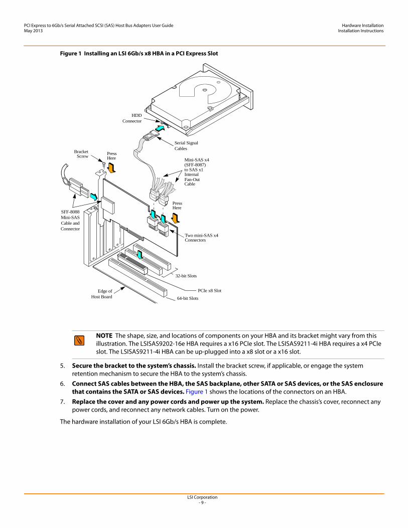
Figure 1 Installing an LSI 6Gb/s x8 HBA in a PCI Express Slot
5. Secure the bracket to the system’s chassis. Install the bracket screw, if applicable, or engage the system retention mechanism to secure the HBA to the system’s chassis.
6. Connect SAS cables between the HBA, the SAS backplane, other SATA or SAS devices, or the SAS enclosure that contains the SATA or SAS devices. Figure 1 shows the locations of the connectors on an HBA.
7. Replace the cover and any power cords and power up the system. Replace the chassis’s cover, reconnect any power cords, and reconnect any network cables. Turn on the power.
The hardware installation of your LSI 6Gb/s HBA is complete.
NOTE The shape, size, and locations of components on your HBA and its bracket might vary from this illustration. The LSISAS9202-16e HBA requires a x16 PCIe slot. The LSISAS9211-4i HBA requires a x4 PCIe slot. The LSISAS9211-4i HBA can be up-plugged into a x8 slot or a x16 slot.
32-bit Slots
64-bit Slots
Edge ofHost Board
Bracket Press
Press
HDDConnector
SFF-8088Mini-SASCable andConnector
Screw
Here
Here
Two mini-SAS x4Connectors
Mini-SAS x4(SFF-8087) to SAS x1InternalFan-OutCable
Serial SignalCables
PCIe x8 Slot
LSI Corporation- 10 -
PCI Express to 6Gb/s Serial Attached SCSI (SAS) Host Bus Adapters User GuideMay 2013
Host Bus Adapter CharacteristicsCharacteristics of the LSI 6Gb/s HBAs
Chapter 3: Host Bus Adapter Characteristics
3.1 Characteristics of the LSI 6Gb/s HBAs
The following sections present the memory, LED, connector, and physical characteristic information for each LSI 6Gb/s HBA.
3.1.1 LSISAS9200-8e HBA Characteristics
3.1.1.1 Memory
The LSISAS9200-8e HBA provides one 4-M × 8-bit Flash ROM for storing the firmware and BIOS.
3.1.1.2 LEDs
The LSISAS9200-8e HBA has a 4-pin header for connection of activity LEDs. The 4-pin header connects to two LEDs (see Table 4), which indicate SAS activity on Port 0 and Port 1.
3.1.1.3 Connectors
This section describes the different connectors on the LSISAS9200-8e HBA. See Figure 2 for connector locations.
PCIe Connector (J7). The LSISAS9200-8e HBA supports a x8 interface. The PCIe host interface connection is through the edge connector, J7, which provides connections on both the top (J7B) and bottom (J7A) of the board. The signal definitions and pin numbers conform to the PCIe specification.
SAS/SATA Connectors (J4 and J5). The LSISAS9200-8e HBA supports SAS/SATA connections through connectors J4 and J5, which are SFF-8088 mini-SAS, external, right-angle connectors.
Activity LED Header (J3). The LSISAS9200-8e HBA has a 4-pin, right-angle, 0.1-in. pitch header for driving external activity LEDs.
UART Connector (TP2). The UART connector debug port requires a special cable and LSI support to gather detailed Input/Output Controller (IOC) status.
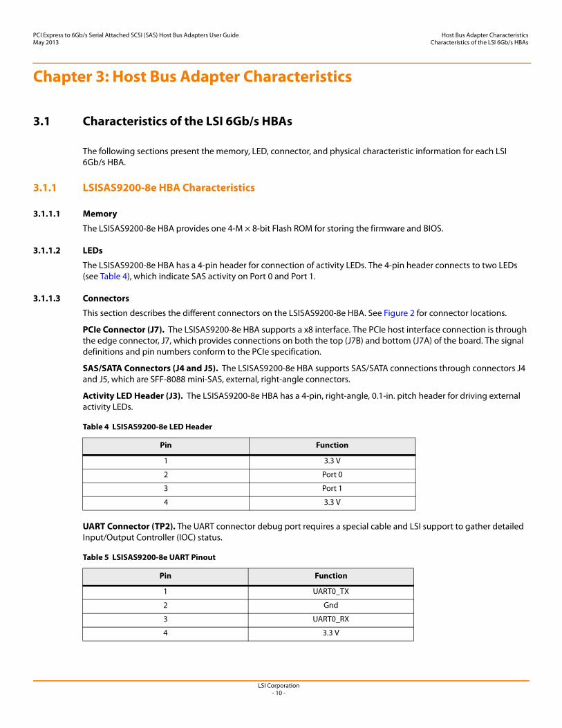
Table 4 LSISAS9200-8e LED Header
Pin Function
1 3.3 V
2 Port 0
3 Port 1
4 3.3 V
Table 5 LSISAS9200-8e UART Pinout
Pin Function
1 UART0_TX
2 Gnd
3 UART0_RX
4 3.3 V
LSI Corporation- 11 -
PCI Express to 6Gb/s Serial Attached SCSI (SAS) Host Bus Adapters User GuideMay 2013
Host Bus Adapter CharacteristicsCharacteristics of the LSI 6Gb/s HBAs
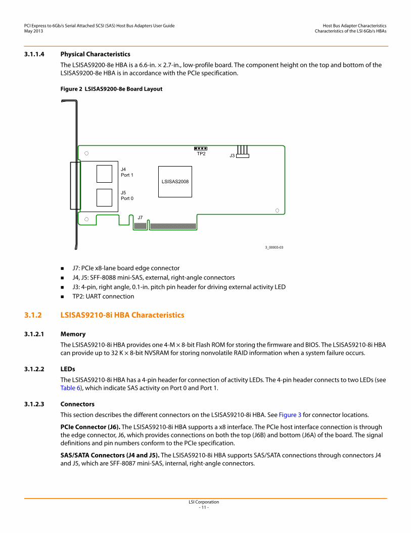
3.1.1.4 Physical Characteristics
The LSISAS9200-8e HBA is a 6.6-in. × 2.7-in., low-profile board. The component height on the top and bottom of the LSISAS9200-8e HBA is in accordance with the PCIe specification.
Figure 2 LSISAS9200-8e Board Layout
J7: PCIe x8-lane board edge connector J4, J5: SFF-8088 mini-SAS, external, right-angle connectors J3: 4-pin, right angle, 0.1-in. pitch pin header for driving external activity LED TP2: UART connection
3.1.2 LSISAS9210-8i HBA Characteristics
3.1.2.1 Memory
The LSISAS9210-8i HBA provides one 4-M × 8-bit Flash ROM for storing the firmware and BIOS. The LSISAS9210-8i HBA can provide up to 32 K × 8-bit NVSRAM for storing nonvolatile RAID information when a system failure occurs.
3.1.2.2 LEDs
The LSISAS9210-8i HBA has a 4-pin header for connection of activity LEDs. The 4-pin header connects to two LEDs (see Table 6), which indicate SAS activity on Port 0 and Port 1.
3.1.2.3 Connectors
This section describes the different connectors on the LSISAS9210-8i HBA. See Figure 3 for connector locations.
PCIe Connector (J6). The LSISAS9210-8i HBA supports a x8 interface. The PCIe host interface connection is through the edge connector, J6, which provides connections on both the top (J6B) and bottom (J6A) of the board. The signal definitions and pin numbers conform to the PCIe specification.
SAS/SATA Connectors (J4 and J5). The LSISAS9210-8i HBA supports SAS/SATA connections through connectors J4 and J5, which are SFF-8087 mini-SAS, internal, right-angle connectors.
LSISAS2008
J4Port 1
J7
TP2 J3
3_00003-03
J5Port 0
LSI Corporation- 12 -
PCI Express to 6Gb/s Serial Attached SCSI (SAS) Host Bus Adapters User GuideMay 2013
Host Bus Adapter CharacteristicsCharacteristics of the LSI 6Gb/s HBAs
Activity LED Header (J3). The LSISAS9210-8i HBA has a 4-pin, right-angle, 0.1-in. pitch header for driving external activity LEDs.
UART Connector (TP1). The UART connector debug port requires a special cable and LSI support to gather detailed IOC status.
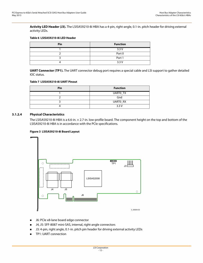
3.1.2.4 Physical Characteristics
The LSISAS9210-8i HBA is a 6.6-in. × 2.7-in. low-profile board. The component height on the top and bottom of the LSISAS9210-8i HBA is in accordance with the PCIe specifications.
Figure 3 LSISAS9210-8i Board Layout
J6: PCIe x8-lane board edge connector J4, J5: SFF-8087 mini-SAS, internal, right-angle connectors J3: 4-pin, right angle, 0.1-in. pitch pin header for driving external activity LEDs TP1: UART connection
Table 6 LSISAS9210-8i LED Header
Pin Function
1 3.3 V2 Port 03 Port 14 3.3 V
Table 7 LSISAS9210-8i UART Pinout
Pin Function
1 UART0_TX2 Gnd3 UART0_RX4 3.3 V
LSISAS2008
J6
J3
3_00004-03
TP1
J4 J5
LSI Corporation- 13 -
PCI Express to 6Gb/s Serial Attached SCSI (SAS) Host Bus Adapters User GuideMay 2013
Host Bus Adapter CharacteristicsCharacteristics of the LSI 6Gb/s HBAs
3.1.3 LSISAS9211-4i HBA Characteristics
3.1.3.1 Memory
The LSISAS9211-4i HBA provides one 4-M × 8-bit Flash ROM for storing the firmware and BIOS. The LSISAS9211-4i HBA can provide up to 32 K × 8-bit NVSRAM for storing nonvolatile RAID information when a system failure occurs.
3.1.3.2 LEDs
The LSISAS9211-4i HBA has a 4-pin header for connection of activity LEDs. The header connects to two LEDs (see Table 8), which indicate SAS activity on port 0 and port 1.
3.1.3.3 Connectors
This section describes the different connectors on the LSISAS9211-4i HBA. See Figure 4 for connector locations.
PCIe Connector (J1). The LSISAS9211-4i HBA supports a x4 interface. The PCIe host interface connection is through the edge connector, J1, which provides connections on both the top (J1B) and bottom (J1A) of the board. The signal definitions and pin numbers conform to the PCIe specifications.
SAS/SATA Connector (J7). The LSISAS9211-4i HBA supports SAS connections through connector J7, which is an SFF-8087 mini-SAS, internal, right-angle connector.
Activity LED Header (J3). The LSISAS9211-4i HBA has a 4-pin, right-angle, 0.1-in. pitch header for driving external activity LEDs.
UART Connector (J5). The UART connector debug port requires a special cable and LSI support to gather detailed IOC status.
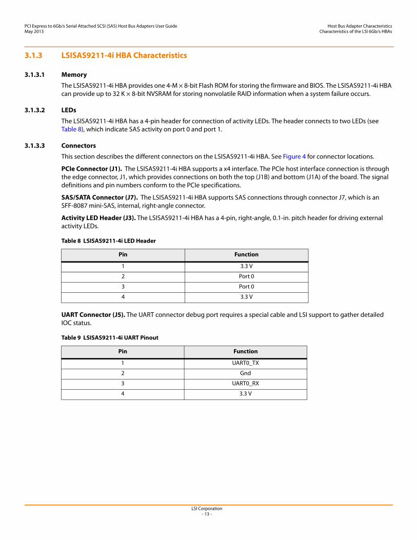
Table 8 LSISAS9211-4i LED Header
Pin Function
1 3.3 V
2 Port 0
3 Port 0
4 3.3 V
Table 9 LSISAS9211-4i UART Pinout
Pin Function
1 UART0_TX
2 Gnd
3 UART0_RX
4 3.3 V
LSI Corporation- 14 -
PCI Express to 6Gb/s Serial Attached SCSI (SAS) Host Bus Adapters User GuideMay 2013
Host Bus Adapter CharacteristicsCharacteristics of the LSI 6Gb/s HBAs
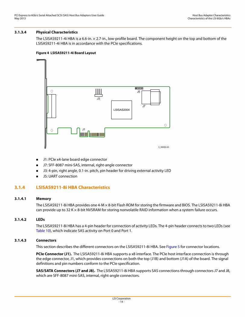
3.1.3.4 Physical Characteristics
The LSISAS9211-4i HBA is a 6.6-in. × 2.7-in., low-profile board. The component height on the top and bottom of the LSISAS9211-4i HBA is in accordance with the PCIe specifications.
Figure 4 LSISAS9211-4i Board Layout
J1: PCIe x4-lane board edge connector J7: SFF-8087 mini-SAS, internal, right-angle connector J3: 4-pin, right angle, 0.1-in. pitch, pin header for driving external activity LED J5: UART connection
3.1.4 LSISAS9211-8i HBA Characteristics
3.1.4.1 Memory
The LSISAS9211-8i HBA provides one 4-M × 8-bit Flash ROM for storing the firmware and BIOS. The LSISAS9211-8i HBA can provide up to 32 K × 8-bit NVSRAM for storing nonvolatile RAID information when a system failure occurs.
3.1.4.2 LEDs
The LSISAS9211-8i HBA has a 4-pin header for connection of activity LEDs. The 4-pin header connects to two LEDs (see Table 10), which indicate SAS activity on Port 0 and Port 1.
3.1.4.3 Connectors
This section describes the different connectors on the LSISAS9211-8i HBA. See Figure 5 for connector locations.
PCIe Connector (J1). The LSISAS9211-8i HBA supports a x8 interface. The PCIe host interface connection is through the edge connector, J1, which provides connections on both the top (J1B) and bottom (J1A) of the board. The signal definitions and pin numbers conform to the PCIe specification.
SAS/SATA Connectors (J7 and J8). The LSISAS9211-8i HBA supports SAS connections through connectors J7 and J8, which are SFF-8087 mini-SAS, internal, right-angle connectors.
LSISAS2004
J1
J3
J5
3_00002-03
J7
LSI Corporation- 15 -
PCI Express to 6Gb/s Serial Attached SCSI (SAS) Host Bus Adapters User GuideMay 2013
Host Bus Adapter CharacteristicsCharacteristics of the LSI 6Gb/s HBAs
Activity LED Header (J6). The LSISAS9211-8i HBA has a 4-pin, right-angle, 0.1-in. pitch header for driving external activity LEDs.
UART Connector (J3). The UART connector debug port requires a special cable and LSI support to gather detailed IOC status.
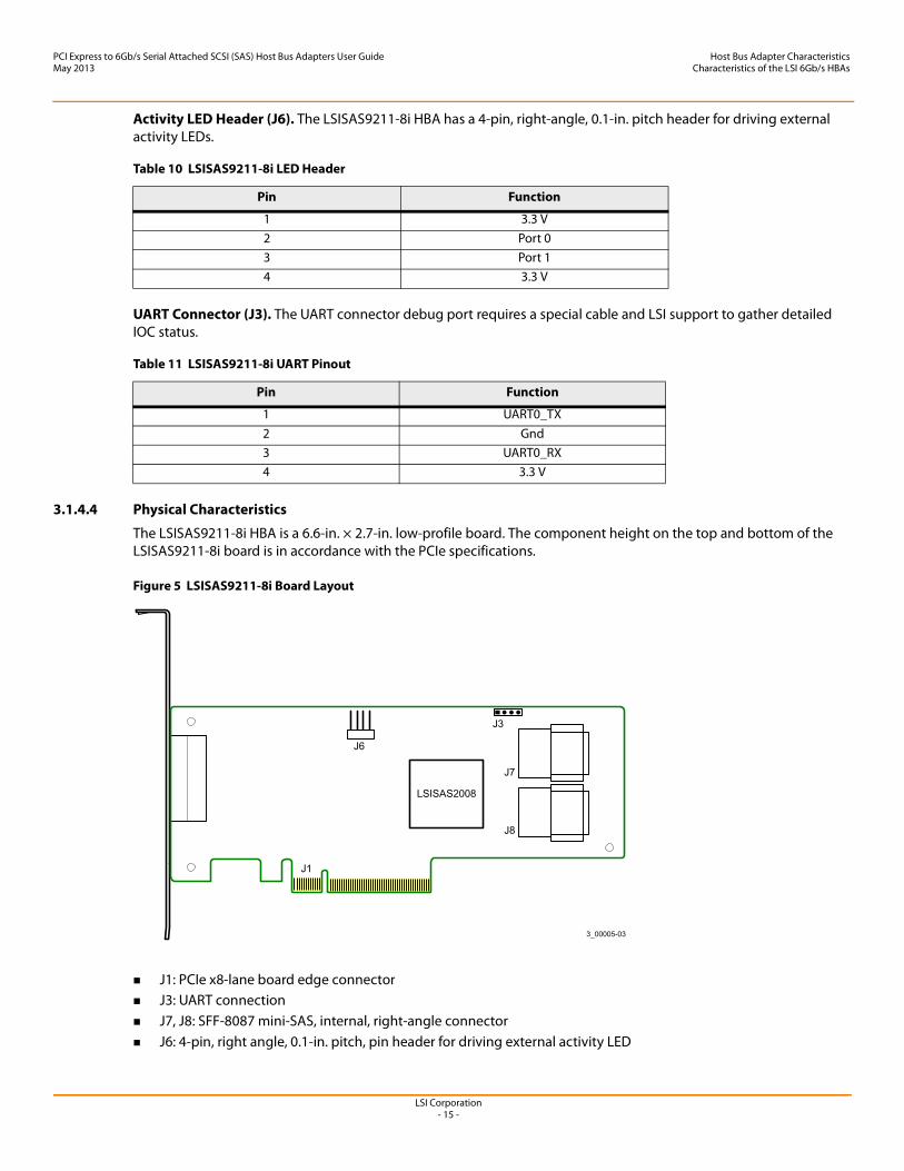
3.1.4.4 Physical Characteristics
The LSISAS9211-8i HBA is a 6.6-in. × 2.7-in. low-profile board. The component height on the top and bottom of the LSISAS9211-8i board is in accordance with the PCIe specifications.
Figure 5 LSISAS9211-8i Board Layout
J1: PCIe x8-lane board edge connector J3: UART connection J7, J8: SFF-8087 mini-SAS, internal, right-angle connector J6: 4-pin, right angle, 0.1-in. pitch, pin header for driving external activity LED
Table 10 LSISAS9211-8i LED Header
Pin Function
1 3.3 V2 Port 03 Port 14 3.3 V
Table 11 LSISAS9211-8i UART Pinout
Pin Function
1 UART0_TX2 Gnd3 UART0_RX4 3.3 V
LSISAS2008
J1
J6
3_00005-03
J3
J7
J8
LSI Corporation- 16 -
PCI Express to 6Gb/s Serial Attached SCSI (SAS) Host Bus Adapters User GuideMay 2013
Host Bus Adapter CharacteristicsCharacteristics of the LSI 6Gb/s HBAs
3.1.5 LSISAS9212-4i4e HBA Characteristics
3.1.5.1 Memory
The LSISAS9212-4i4e HBA provides one 4-M × 8-bit Flash ROM for storing the firmware and BIOS. The LSISAS9212-4i4e HBA can provide up to 32 K × 8-bit NVSRAM for storing nonvolatile RAID information when a system failure occurs.
3.1.5.2 LEDs
The LSISAS9212-4i4e HBA has a 4-pin header for external connection of activity LEDs. The 4-pin header connects to two LEDs (see Table 12), which indicate SAS activity on Port 0 and Port 1.
3.1.5.3 Connectors
This section describes the different connectors on the LSISAS9212-4i4e HBA. See Figure 6 for connector locations.
PCIe Connector (J1). The LSISAS9212-4i4e HBA supports a x8 interface. The PCIe host interface connection is through the edge connector, J1, which provides connections on both the top (J1B) and bottom (J1A) of the board. The signal definitions and pin numbers conform to the PCIe specifications.
SAS/SATA Connector (J5, J6, J7, J8, and J12). The LSISAS9212-4i4e HBA supports SAS/SATA connections through connector J12, which is an SFF-8088 mini-SAS, external, right-angle connector, and connectors J5, J6, J7, and J8, which are 7-pin SATA connectors.
Activity LED Header (J11). The LSISAS9212-4i4e HBA has a 4-pin, right-angle, 0.1-in. pitch header for driving external activity LEDs.
UART Connector (J4). The UART connector debug port requires a special cable and LSI support to gather detailed IOC status.
Table 12 LSISAS9212-4i4e LED Header
Pin Function
1 3.3 V
2 Port 0
3 Port 1a
a. Port 1 consists of the 7-pin SATA connectors on this HBA.
4 3.3 V
Table 13 LSISAS9212-4i4e UART Pinout
Pin Function
1 UART_TX
2 Gnd
3 UART_RX
4 3.3 V

LSI Corporation- 17 -
PCI Express to 6Gb/s Serial Attached SCSI (SAS) Host Bus Adapters User GuideMay 2013
Host Bus Adapter CharacteristicsCharacteristics of the LSI 6Gb/s HBAs
3.1.5.4 Physical Characteristics
The LSISAS9212-4i4e HBA is a 6.6-in. × 2.7-in. low-profile board. The component height on the top and bottom of the LSISAS9212-4i4e HBA is in accordance with the PCIe specification.
Figure 6 LSISAS9212-4i4e Board Layout
J1: PCIe x4-lane board edge connector J12: SFF-8088 mini-SAS, external, right-angle connector J5, J6, J7, J8: x1, internal 7-pin SATA connectors J11: 4-pin, right angle, 0.1-in. pitch, pin header for driving external activity LED J4: UART connection
3.1.6 LSISAS9200-16e HBA Characteristics
The LSISAS9200-16e HBA supports active copper cable and passive copper cable.
3.1.6.1 Memory
The LSISAS9200-16e HBA provides one 2-M × 16-bit Flash ROM for storing the firmware and BIOS, and provides onboard DDR2 SDRAM.
3.1.6.2 LEDs
The LSISAS9200-16e HBA has two 4-pin headers for external connection of activity LEDs. The LEDs on header J4 correspond to activity on ports 2 and 3, and header J5 corresponds to activity on Port 0 and Port 1.
3.1.6.3 Connectors
This section describes the different connectors on the LSISAS9200-16e HBA. See Figure 7 for connector locations.
PCIe Connector (J10). The LSISAS9200-16e HBA supports a x8 interface. The PCIe host interface connection is through the edge connector, J10, which provides connections on both the top (J10B) and bottom (J10A) of the board. The signal definitions and pin numbers conform to the PCIe specification.
J5
J4
J6 J7 J8
J11
J1
J12Port 0
LSISAS2008
3_00134-03
LSI Corporation- 18 -
PCI Express to 6Gb/s Serial Attached SCSI (SAS) Host Bus Adapters User GuideMay 2013
Host Bus Adapter CharacteristicsCharacteristics of the LSI 6Gb/s HBAs
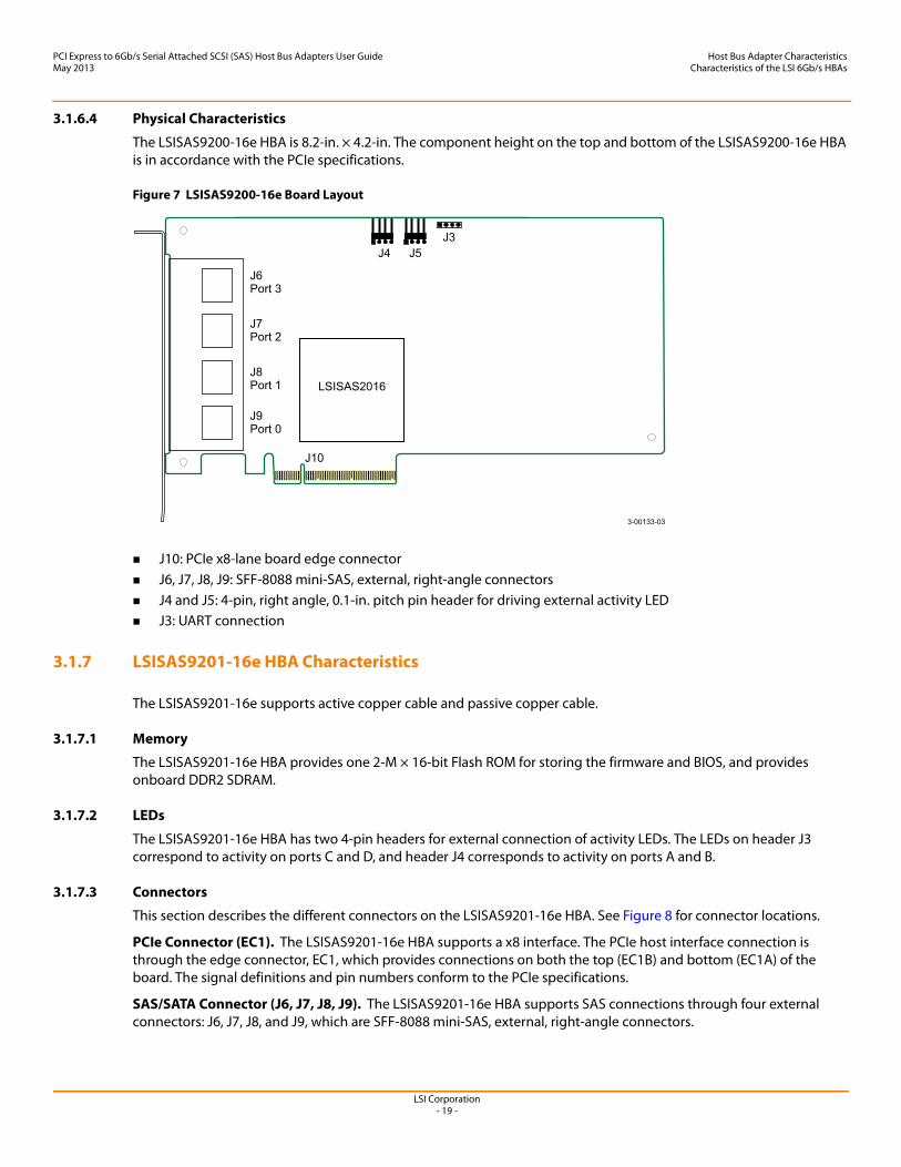
SAS/SATA Connector (J6, J7, J8, J9). The LSISAS9200-16e HBA supports SAS connections through four external connectors: J6, J7, J8, and J9, which are SFF-8088 mini-SAS, external, right-angle connectors.
Activity LED Headers (J4 and J5). The LSISAS9200-16e HBA has two 4-pin, right-angle, 0.1-in. pitch headers for driving external activity LEDs.
UART Connector (J3). The UART connector debug port requires a special cable and LSI support to gather detailed IOC status.
Table 14 LSISAS9200-16e LED Header for J4
Pin Function
1 3.3 V
2 Port 2
3 Port 3
4 3.3 V
Table 15 LSISAS9200-16e LED Header for J5
Pin Function
1 3.3 V
2 Port 0
3 Port 1
4 3.3 V
Table 16 LSISAS9200-16e UART Pinout
Pin Function
1 UART_TX
2 Gnd
3 UART_RX
4 3.3 V
LSI Corporation- 19 -
PCI Express to 6Gb/s Serial Attached SCSI (SAS) Host Bus Adapters User GuideMay 2013
Host Bus Adapter CharacteristicsCharacteristics of the LSI 6Gb/s HBAs
3.1.6.4 Physical Characteristics
The LSISAS9200-16e HBA is 8.2-in. × 4.2-in. The component height on the top and bottom of the LSISAS9200-16e HBA is in accordance with the PCIe specifications.
Figure 7 LSISAS9200-16e Board Layout
J10: PCIe x8-lane board edge connector J6, J7, J8, J9: SFF-8088 mini-SAS, external, right-angle connectors J4 and J5: 4-pin, right angle, 0.1-in. pitch pin header for driving external activity LED J3: UART connection
3.1.7 LSISAS9201-16e HBA Characteristics
The LSISAS9201-16e supports active copper cable and passive copper cable.
3.1.7.1 Memory
The LSISAS9201-16e HBA provides one 2-M × 16-bit Flash ROM for storing the firmware and BIOS, and provides onboard DDR2 SDRAM.
3.1.7.2 LEDs
The LSISAS9201-16e HBA has two 4-pin headers for external connection of activity LEDs. The LEDs on header J3 correspond to activity on ports C and D, and header J4 corresponds to activity on ports A and B.
3.1.7.3 Connectors
This section describes the different connectors on the LSISAS9201-16e HBA. See Figure 8 for connector locations.
PCIe Connector (EC1). The LSISAS9201-16e HBA supports a x8 interface. The PCIe host interface connection is through the edge connector, EC1, which provides connections on both the top (EC1B) and bottom (EC1A) of the board. The signal definitions and pin numbers conform to the PCIe specifications.
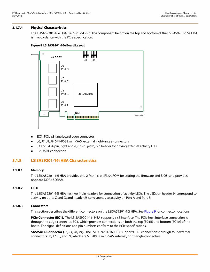
SAS/SATA Connector (J6, J7, J8, J9). The LSISAS9201-16e HBA supports SAS connections through four external connectors: J6, J7, J8, and J9, which are SFF-8088 mini-SAS, external, right-angle connectors.
J6Port 3
J7Port 2
J8Port 1
J9Port 0
J10
J4J3
J5
LSISAS2016
3-00133-03
LSI Corporation- 20 -
PCI Express to 6Gb/s Serial Attached SCSI (SAS) Host Bus Adapters User GuideMay 2013
Host Bus Adapter CharacteristicsCharacteristics of the LSI 6Gb/s HBAs
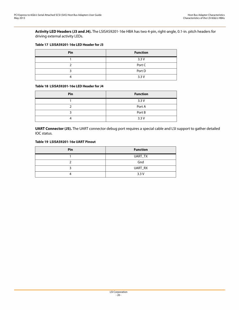
Activity LED Headers (J3 and J4). The LSISAS9201-16e HBA has two 4-pin, right-angle, 0.1-in. pitch headers for driving external activity LEDs.
UART Connector (J5). The UART connector debug port requires a special cable and LSI support to gather detailed IOC status.
Table 17 LSISAS9201-16e LED Header for J3
Pin Function
1 3.3 V
2 Port C
3 Port D
4 3.3 V
Table 18 LSISAS9201-16e LED Header for J4
Pin Function
1 3.3 V
2 Port A
3 Port B
4 3.3 V
Table 19 LSISAS9201-16e UART Pinout
Pin Function
1 UART_TX
2 Gnd
3 UART_RX
4 3.3 V
LSI Corporation- 21 -
PCI Express to 6Gb/s Serial Attached SCSI (SAS) Host Bus Adapters User GuideMay 2013
Host Bus Adapter CharacteristicsCharacteristics of the LSI 6Gb/s HBAs
3.1.7.4 Physical Characteristics
The LSISAS9201-16e HBA is 6.6-in. × 4.2-in. The component height on the top and bottom of the LSISAS9201-16e HBA is in accordance with the PCIe specification.
Figure 8 LSISAS9201-16e Board Layout
EC1: PCIe x8-lane board edge connector J6, J7, J8, J9: SFF-8088 mini-SAS, external, right-angle connectors J3 and J4: 4-pin, right angle, 0.1-in. pitch, pin header for driving external activity LED J5: UART connection
3.1.8 LSISAS9201-16i HBA Characteristics
3.1.8.1 Memory
The LSISAS9201-16i HBA provides one 2-M × 16-bit Flash ROM for storing the firmware and BIOS, and provides onboard DDR2 SDRAM.
3.1.8.2 LEDs
The LSISAS9201-16i HBA has two 4-pin headers for connection of activity LEDs. The LEDs on header J4 correspond to activity on ports C and D, and header J5 corresponds to activity on Port A and Port B.
3.1.8.3 Connectors
This section describes the different connectors on the LSISAS9201-16i HBA. See Figure 9 for connector locations.
PCIe Connector (EC1). The LSISAS9201-16i HBA supports a x8 interface. The PCIe host interface connection is through the edge connector, EC1, which provides connections on both the top (EC1B) and bottom (EC1A) of the board. The signal definitions and pin numbers conform to the PCIe specifications.
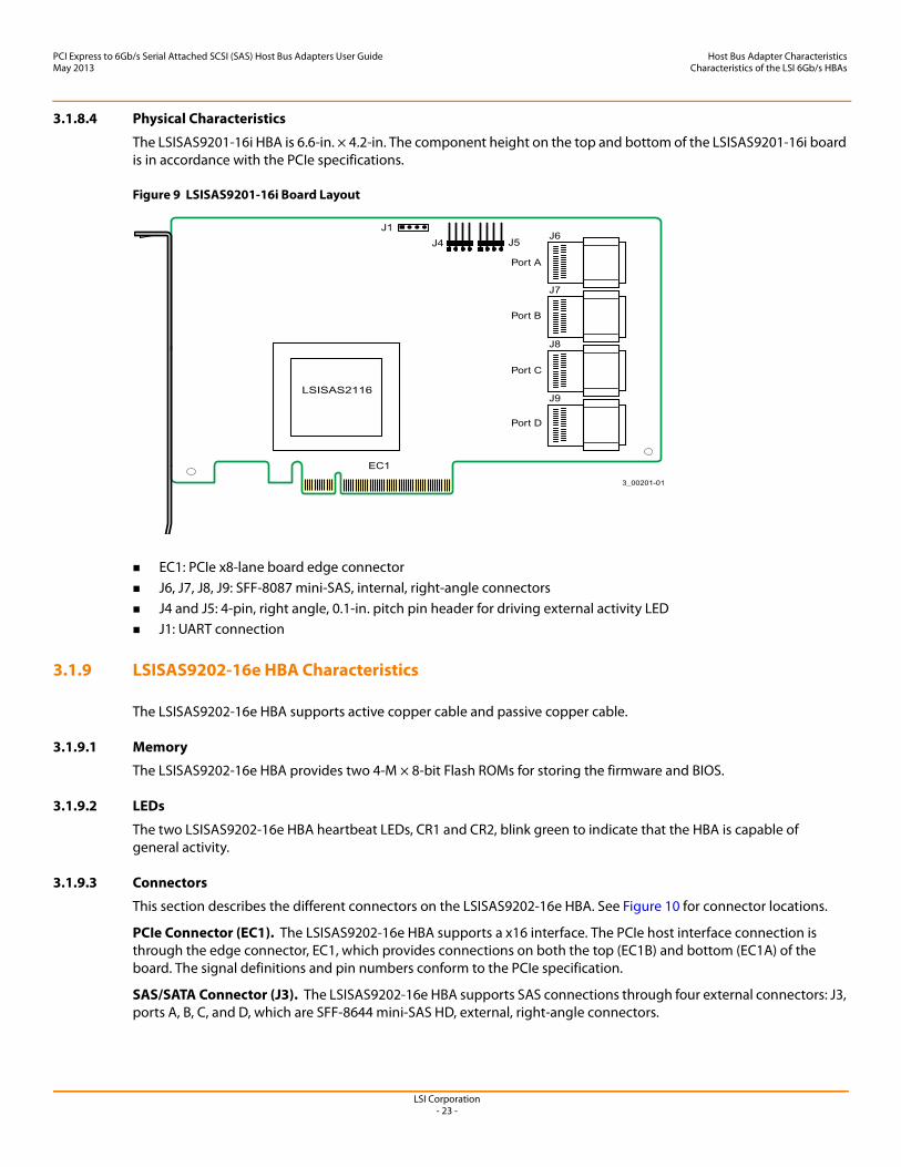
SAS/SATA Connector (J6, J7, J8, J9). The LSISAS9201-16i HBA supports SAS connections through four external connectors: J6, J7, J8, and J9, which are SFF-8087 mini-SAS, internal, right-angle connectors.
3-00205-01
J6Port D
J7
J8
J9Port A
Port B
Port C
EC1
J3 J4
LSISAS2016
J5

LSI Corporation- 22 -
PCI Express to 6Gb/s Serial Attached SCSI (SAS) Host Bus Adapters User GuideMay 2013
Host Bus Adapter CharacteristicsCharacteristics of the LSI 6Gb/s HBAs
Activity LED Headers (J4 and J5). The LSISAS9201-16i HBA has two 4-pin, right-angle, 0.1-in. pitch headers for driving external activity LEDs.
UART Connector (J1). The UART connector debug port requires a special cable and LSI support to gather detailed IOC status.
Table 20 LSISAS9201-16i LED Header for J4
Pin Function
1 3.3 V
2 Port C
3 Port D
4 3.3 V
Table 21 LSISAS9201-16i LED Header for J5
Pin Function
1 3.3 V
2 Port A
3 Port B
4 3.3 V
Table 22 LSISAS9201-16i UART Pinout
Pin Function
1 UART_TX
2 Gnd
3 UART_RX
4 3.3 V
LSI Corporation- 23 -
PCI Express to 6Gb/s Serial Attached SCSI (SAS) Host Bus Adapters User GuideMay 2013
Host Bus Adapter CharacteristicsCharacteristics of the LSI 6Gb/s HBAs
3.1.8.4 Physical Characteristics
The LSISAS9201-16i HBA is 6.6-in. × 4.2-in. The component height on the top and bottom of the LSISAS9201-16i board is in accordance with the PCIe specifications.
Figure 9 LSISAS9201-16i Board Layout
EC1: PCIe x8-lane board edge connector J6, J7, J8, J9: SFF-8087 mini-SAS, internal, right-angle connectors J4 and J5: 4-pin, right angle, 0.1-in. pitch pin header for driving external activity LED J1: UART connection
3.1.9 LSISAS9202-16e HBA Characteristics
The LSISAS9202-16e HBA supports active copper cable and passive copper cable.
3.1.9.1 Memory
The LSISAS9202-16e HBA provides two 4-M × 8-bit Flash ROMs for storing the firmware and BIOS.
3.1.9.2 LEDs
The two LSISAS9202-16e HBA heartbeat LEDs, CR1 and CR2, blink green to indicate that the HBA is capable of general activity.
3.1.9.3 Connectors
This section describes the different connectors on the LSISAS9202-16e HBA. See Figure 10 for connector locations.
PCIe Connector (EC1). The LSISAS9202-16e HBA supports a x16 interface. The PCIe host interface connection is through the edge connector, EC1, which provides connections on both the top (EC1B) and bottom (EC1A) of the board. The signal definitions and pin numbers conform to the PCIe specification.
SAS/SATA Connector (J3). The LSISAS9202-16e HBA supports SAS connections through four external connectors: J3, ports A, B, C, and D, which are SFF-8644 mini-SAS HD, external, right-angle connectors.
LSI Corporation- 24 -
PCI Express to 6Gb/s Serial Attached SCSI (SAS) Host Bus Adapters User GuideMay 2013
Host Bus Adapter CharacteristicsCharacteristics of the LSI 6Gb/s HBAs
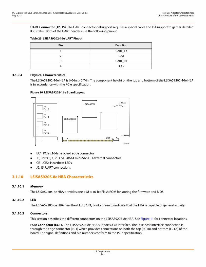
UART Connector (J2, J5). The UART connector debug port requires a special cable and LSI support to gather detailed IOC status. Both of the UART headers use the following pinout.
3.1.9.4 Physical Characteristics
The LSISAS9202-16e HBA is 6.6-in. × 2.7-in. The component height on the top and bottom of the LSISAS9202-16e HBA is in accordance with the PCIe specification.
Figure 10 LSISAS9202-16e Board Layout
EC1: PCIe x16-lane board edge connector J3, Ports 0, 1, 2, 3: SFF-8644 mini-SAS HD external connectors CR1, CR2: Heartbeat LEDs J2, J5: UART connections
3.1.10 LSISAS9205-8e HBA Characteristics
3.1.10.1 Memory
The LSISAS9205-8e HBA provides one 4-M × 16-bit Flash ROM for storing the firmware and BIOS.
3.1.10.2 LED
The LSISAS9205-8e HBA heartbeat LED, CR1, blinks green to indicate that the HBA is capable of general activity.
3.1.10.3 Connectors
This section describes the different connectors on the LSISAS9205-8e HBA. See Figure 11 for connector locations.
PCIe Connector (EC1). The LSISAS9205-8e HBA supports a x8 interface. The PCIe host interface connection is through the edge connector (EC1) which provides connections on both the top (EC1B) and bottom (EC1A) of the board. The signal definitions and pin numbers conform to the PCIe specification.
Table 23 LSISAS9202-16e UART Pinout
Pin Function
1 UART_TX
2 Gnd
3 UART_RX
4 3.3 V
LSI Corporation- 25 -
PCI Express to 6Gb/s Serial Attached SCSI (SAS) Host Bus Adapters User GuideMay 2013
Host Bus Adapter CharacteristicsCharacteristics of the LSI 6Gb/s HBAs
SAS/SATA Connectors (J5 and J6). The LSISAS9205-8e HBA supports SAS/SATA connections through connectors J5 and J6, which are SFF-8088 mini-SAS, external, right-angle connectors.
UART Connector (J4). The UART connector debug port requires a special cable and LSI support to gather detailed IOC status.
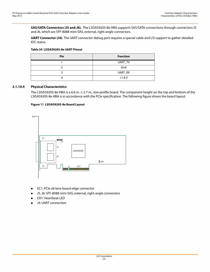
3.1.10.4 Physical Characteristics
The LSISAS9205-8e HBA is a 6.6-in. × 2.7-in., low-profile board. The component height on the top and bottom of the LSISAS9205-8e HBA is in accordance with the PCIe specification. The following figure shows the board layout.
Figure 11 LSISAS9205-8e Board Layout
EC1: PCIe x8-lane board edge connector J5, J6: SFF-8088 mini-SAS, external, right-angle connectors CR1: Heartbeat LED J4: UART connection
Table 24 LSISAS9205-8e UART Pinout
Pin Function
1 UART_TX
2 Gnd
3 UART_RX
4 +1.8 V
LSI Corporation- 26 -
PCI Express to 6Gb/s Serial Attached SCSI (SAS) Host Bus Adapters User GuideMay 2013
Host Bus Adapter CharacteristicsCharacteristics of the LSI 6Gb/s HBAs
3.1.11 LSISAS9207-8e HBA Characteristics
The LSISAS9207-8e HBA supports active copper cable and passive copper cable.
3.1.11.1 Memory
The LSISAS9207-8e HBA provides one 4 M × 16-bit Flash ROM for storing the firmware and BIOS.
3.1.11.2 LED
The LSISAS9207-8e HBA heartbeat LED, CR1, blinks green to indicate that the HBA is capable of general activity.
3.1.11.3 Connectors
This section describes the different connectors on the LSISAS9207-8e HBA. See Figure 12 for connector locations.
PCIe Connector (EC1). The LSISAS9207-8e HBA supports a x8 interface. The PCIe host interface connection is through the edge connector (EC1) which provides connections on both the top (EC1B) and bottom (EC1A) of the board. The signal definitions and pin numbers conform to the PCIe specification.
SAS/SATA Connectors (J10 and J11). The LSISAS9207-8e HBA supports SAS/SATA connections through connectors J10 and J11, which are SFF-8088 mini-SAS, external, right-angle connectors.
UART Connector (J4).The UART connector debug port requires a special cable and LSI support to gather detailed IOC status.
Table 25 LSISAS9207-8e UART Pinout
Pin Function
1 UART0_TX
2 Gnd
3 UART0_RX
4 +1.8 V
LSI Corporation- 27 -
PCI Express to 6Gb/s Serial Attached SCSI (SAS) Host Bus Adapters User GuideMay 2013
Host Bus Adapter CharacteristicsCharacteristics of the LSI 6Gb/s HBAs
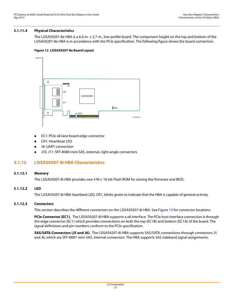
3.1.11.4 Physical Characteristics
The LSISAS9207-8e HBA is a 6.6-in. × 2.7-in., low-profile board. The component height on the top and bottom of the LSISAS9207-8e HBA is in accordance with the PCIe specification. The following figure shows the board connectors.
Figure 12 LSISAS9207-8e Board Layout
EC1: PCIe x8-lane board edge connector CR1: Heartbeat LED J4: UART connection J10, J11: SFF-8088 mini-SAS, external, right-angle connectors
3.1.12 LSISAS9207-8i HBA Characteristics
3.1.12.1 Memory
The LSISAS9207-8i HBA provides one 4 M × 16-bit Flash ROM for storing the firmware and BIOS.
3.1.12.2 LED
The LSISAS9207-8i HBA heartbeat LED, CR1, blinks green to indicate that the HBA is capable of general activity.
3.1.12.3 Connectors
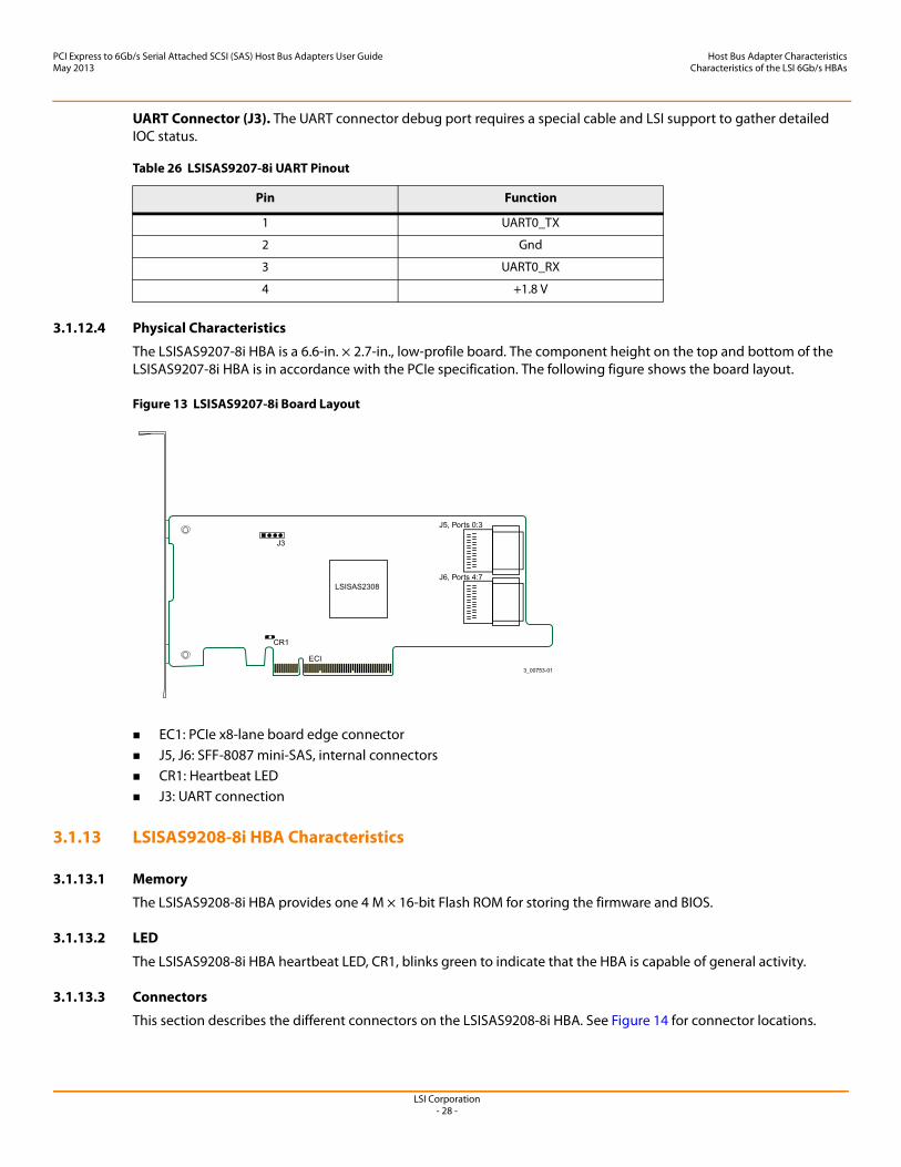
This section describes the different connectors on the LSISAS9207-8i HBA. See Figure 13 for connector locations.
PCIe Connector (EC1). The LSISAS9207-8i HBA supports a x8 interface. The PCIe host interface connection is through the edge connector (EC1) which provides connections on both the top (EC1B) and bottom (EC1A) of the board. The signal definitions and pin numbers conform to the PCIe specification.
SAS/SATA Connectors (J5 and J6). The LSISAS9207-8i HBA supports SAS/SATA connections through connectors J5 and J6, which are SFF-8087 mini-SAS, internal connectors. The HBA supports SAS sideband signal assignments.
LSI Corporation- 28 -
PCI Express to 6Gb/s Serial Attached SCSI (SAS) Host Bus Adapters User GuideMay 2013
Host Bus Adapter CharacteristicsCharacteristics of the LSI 6Gb/s HBAs
UART Connector (J3). The UART connector debug port requires a special cable and LSI support to gather detailed IOC status.
3.1.12.4 Physical Characteristics
The LSISAS9207-8i HBA is a 6.6-in. × 2.7-in., low-profile board. The component height on the top and bottom of the LSISAS9207-8i HBA is in accordance with the PCIe specification. The following figure shows the board layout.
Figure 13 LSISAS9207-8i Board Layout
EC1: PCIe x8-lane board edge connector J5, J6: SFF-8087 mini-SAS, internal connectors CR1: Heartbeat LED J3: UART connection
3.1.13 LSISAS9208-8i HBA Characteristics
3.1.13.1 Memory
The LSISAS9208-8i HBA provides one 4 M × 16-bit Flash ROM for storing the firmware and BIOS.
3.1.13.2 LED
The LSISAS9208-8i HBA heartbeat LED, CR1, blinks green to indicate that the HBA is capable of general activity.
3.1.13.3 Connectors
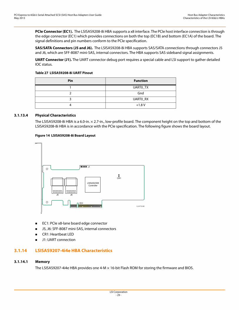
This section describes the different connectors on the LSISAS9208-8i HBA. See Figure 14 for connector locations.
Table 26 LSISAS9207-8i UART Pinout
Pin Function
1 UART0_TX
2 Gnd
3 UART0_RX
4 +1.8 V
LSI Corporation- 29 -
PCI Express to 6Gb/s Serial Attached SCSI (SAS) Host Bus Adapters User GuideMay 2013
Host Bus Adapter CharacteristicsCharacteristics of the LSI 6Gb/s HBAs
PCIe Connector (EC1). The LSISAS9208-8i HBA supports a x8 interface. The PCIe host interface connection is through the edge connector (EC1) which provides connections on both the top (EC1B) and bottom (EC1A) of the board. The signal definitions and pin numbers conform to the PCIe specification.
SAS/SATA Connectors (J5 and J6). The LSISAS9208-8i HBA supports SAS/SATA connections through connectors J5 and J6, which are SFF-8087 mini-SAS, internal connectors. The HBA supports SAS sideband signal assignments.
UART Connector (J1). The UART connector debug port requires a special cable and LSI support to gather detailed IOC status.
3.1.13.4 Physical Characteristics
The LSISAS9208-8i HBA is a 6.0-in. × 2.7-in., low-profile board. The component height on the top and bottom of the LSISAS9208-8i HBA is in accordance with the PCIe specification. The following figure shows the board layout.
Figure 14 LSISAS9208-8i Board Layout
EC1: PCIe x8-lane board edge connector J5, J6: SFF-8087 mini-SAS, internal connectors CR1: Heartbeat LED J1: UART connection
3.1.14 LSISAS9207-4i4e HBA Characteristics
3.1.14.1 Memory
The LSISAS9207-4i4e HBA provides one 4-M × 16-bit Flash ROM for storing the firmware and BIOS.
Table 27 LSISAS9208-8i UART Pinout
Pin Function
1 UART0_TX
2 Gnd
3 UART0_RX
4 +1.8 V
LSI Corporation- 30 -
PCI Express to 6Gb/s Serial Attached SCSI (SAS) Host Bus Adapters User GuideMay 2013
Host Bus Adapter CharacteristicsCharacteristics of the LSI 6Gb/s HBAs
3.1.14.2 LED
The LSISAS9207-4i4e HBA heartbeat LED, CR1, blinks green to indicate that the HBA is capable of general activity.
3.1.14.3 Connectors
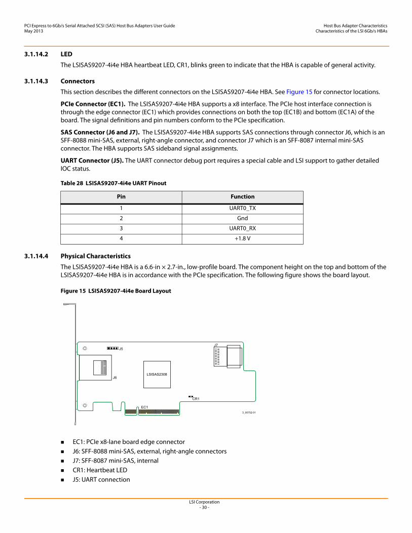
This section describes the different connectors on the LSISAS9207-4i4e HBA. See Figure 15 for connector locations.
PCIe Connector (EC1). The LSISAS9207-4i4e HBA supports a x8 interface. The PCIe host interface connection is through the edge connector (EC1) which provides connections on both the top (EC1B) and bottom (EC1A) of the board. The signal definitions and pin numbers conform to the PCIe specification.
SAS Connector (J6 and J7). The LSISAS9207-4i4e HBA supports SAS connections through connector J6, which is an SFF-8088 mini-SAS, external, right-angle connector, and connector J7 which is an SFF-8087 internal mini-SAS connector. The HBA supports SAS sideband signal assignments.
UART Connector (J5). The UART connector debug port requires a special cable and LSI support to gather detailed IOC status.
3.1.14.4 Physical Characteristics
The LSISAS9207-4i4e HBA is a 6.6-in × 2.7-in., low-profile board. The component height on the top and bottom of the LSISAS9207-4i4e HBA is in accordance with the PCIe specification. The following figure shows the board layout.
Figure 15 LSISAS9207-4i4e Board Layout
EC1: PCIe x8-lane board edge connector J6: SFF-8088 mini-SAS, external, right-angle connectors J7: SFF-8087 mini-SAS, internal CR1: Heartbeat LED J5: UART connection
Table 28 LSISAS9207-4i4e UART Pinout
Pin Function
1 UART0_TX
2 Gnd
3 UART0_RX
4 +1.8 V
LSI Corporation- 31 -
PCI Express to 6Gb/s Serial Attached SCSI (SAS) Host Bus Adapters User GuideMay 2013
Host Bus Adapter CharacteristicsCharacteristics of the LSI 6Gb/s HBAs
3.1.15 LSISAS9217-8i HBA Characteristics
3.1.15.1 Memory
The LSISAS9217-8i HBA provides one 4 M × 16-bit Flash ROM for storing the firmware and BIOS. The LSISAS9217-8i HBA can provide up to 32 K × 8-bit NVSRAM for storing the nonvolatile RAID information when a system failure occurs.
3.1.15.2 LED
The LSISAS9217-8i HBA heartbeat LED, CR1, blinks green to indicate that the HBA is capable of general activity.
3.1.15.3 Connectors
This section describes the different connectors on the LSISAS9217-8i HBA. See Figure 16 for connector locations.
PCIe Connector (EC1). The LSISAS9217-8i HBA supports a x8 interface. The PCIe host interface connection is through the edge connector (EC1) which provides connections on both the top (EC1B) and bottom (EC1A) of the board. The signal definitions and pin numbers conform to the PCIe specification.
SAS/SATA Connectors (J5 and J6). The LSISAS9217-8i HBA supports SAS/SATA connections through connectors J5 and J6, which are SFF-8087 mini-SAS, internal connectors. The HBA supports SAS sideband signal assignments.
UART Connector (J3). The UART connector debug port requires a special cable and LSI support to gather detailed IOC status.
3.1.15.4 Physical Characteristics
The LSISAS9217-8i HBA is a 6.6-in. × 2.7-in., low-profile board. The component height on the top and bottom of the LSISAS9217-8i HBA is in accordance with the PCIe specification. The following figure shows the board layout.
Table 29 LSISAS9217-8i UART Pinout
Pin Function
1 UART0_TX
2 Gnd
3 UART0_RX
4 +1.8 V
LSI Corporation- 32 -
PCI Express to 6Gb/s Serial Attached SCSI (SAS) Host Bus Adapters User GuideMay 2013
Host Bus Adapter CharacteristicsCharacteristics of the LSI 6Gb/s HBAs
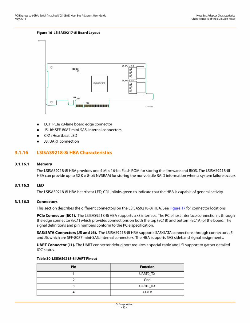
Figure 16 LSISAS9217-8i Board Layout
EC1: PCIe x8-lane board edge connector J5, J6: SFF-8087 mini-SAS, internal connectors CR1: Heartbeat LED J3: UART connection
3.1.16 LSISAS9218-8i HBA Characteristics
3.1.16.1 Memory
The LSISAS9218-8i HBA provides one 4 M × 16-bit Flash ROM for storing the firmware and BIOS. The LSISAS9218-8i HBA can provide up to 32 K × 8-bit NVSRAM for storing the nonvolatile RAID information when a system failure occurs
3.1.16.2 LED
The LSISAS9218-8i HBA heartbeat LED, CR1, blinks green to indicate that the HBA is capable of general activity.
3.1.16.3 Connectors
This section describes the different connectors on the LSISAS9218-8i HBA. See Figure 17 for connector locations.
PCIe Connector (EC1). The LSISAS9218-8i HBA supports a x8 interface. The PCIe host interface connection is through the edge connector (EC1) which provides connections on both the top (EC1B) and bottom (EC1A) of the board. The signal definitions and pin numbers conform to the PCIe specification.
SAS/SATA Connectors (J5 and J6). The LSISAS9218-8i HBA supports SAS/SATA connections through connectors J5 and J6, which are SFF-8087 mini-SAS, internal connectors. The HBA supports SAS sideband signal assignments.
UART Connector (J1). The UART connector debug port requires a special cable and LSI support to gather detailed IOC status.
Table 30 LSISAS9218-8i UART Pinout
Pin Function
1 UART0_TX
2 Gnd
3 UART0_RX
4 +1.8 V
LSI Corporation- 33 -
PCI Express to 6Gb/s Serial Attached SCSI (SAS) Host Bus Adapters User GuideMay 2013
Host Bus Adapter CharacteristicsCharacteristics of the LSI 6Gb/s HBAs
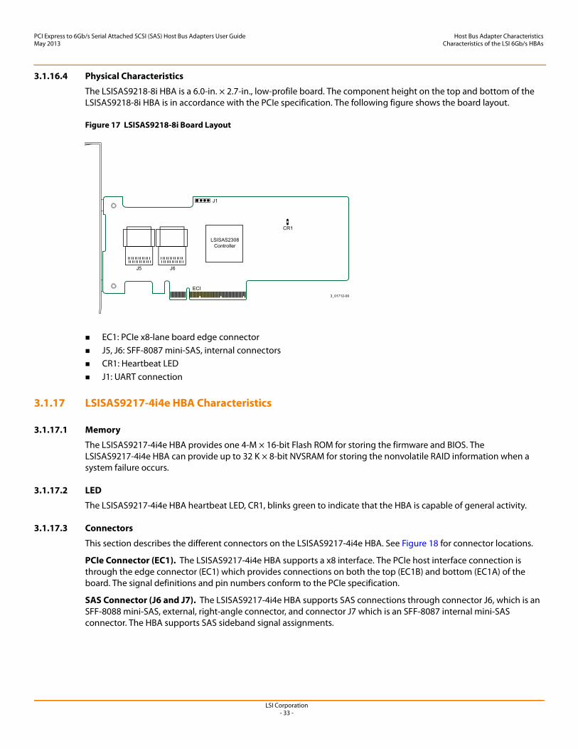
3.1.16.4 Physical Characteristics
The LSISAS9218-8i HBA is a 6.0-in. × 2.7-in., low-profile board. The component height on the top and bottom of the LSISAS9218-8i HBA is in accordance with the PCIe specification. The following figure shows the board layout.
Figure 17 LSISAS9218-8i Board Layout
EC1: PCIe x8-lane board edge connector J5, J6: SFF-8087 mini-SAS, internal connectors CR1: Heartbeat LED J1: UART connection
3.1.17 LSISAS9217-4i4e HBA Characteristics
3.1.17.1 Memory
The LSISAS9217-4i4e HBA provides one 4-M × 16-bit Flash ROM for storing the firmware and BIOS. The LSISAS9217-4i4e HBA can provide up to 32 K × 8-bit NVSRAM for storing the nonvolatile RAID information when a system failure occurs.
3.1.17.2 LED
The LSISAS9217-4i4e HBA heartbeat LED, CR1, blinks green to indicate that the HBA is capable of general activity.
3.1.17.3 Connectors
This section describes the different connectors on the LSISAS9217-4i4e HBA. See Figure 18 for connector locations.
PCIe Connector (EC1). The LSISAS9217-4i4e HBA supports a x8 interface. The PCIe host interface connection is through the edge connector (EC1) which provides connections on both the top (EC1B) and bottom (EC1A) of the board. The signal definitions and pin numbers conform to the PCIe specification.
SAS Connector (J6 and J7). The LSISAS9217-4i4e HBA supports SAS connections through connector J6, which is an SFF-8088 mini-SAS, external, right-angle connector, and connector J7 which is an SFF-8087 internal mini-SAS connector. The HBA supports SAS sideband signal assignments.
LSI Corporation- 34 -
PCI Express to 6Gb/s Serial Attached SCSI (SAS) Host Bus Adapters User GuideMay 2013
Host Bus Adapter CharacteristicsCharacteristics of the LSI 6Gb/s HBAs
UART Connector (J5). The UART connector debug port requires a special cable and LSI support to gather detailed IOC status.
3.1.17.4 Physical Characteristics
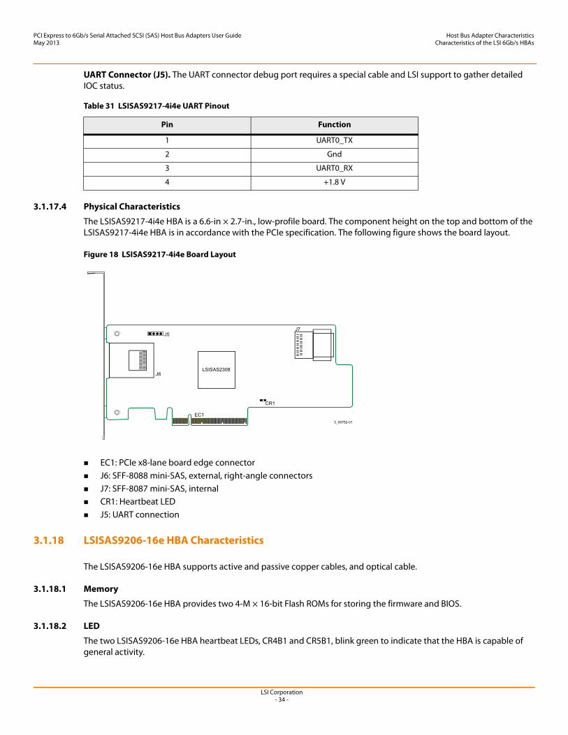
The LSISAS9217-4i4e HBA is a 6.6-in × 2.7-in., low-profile board. The component height on the top and bottom of the LSISAS9217-4i4e HBA is in accordance with the PCIe specification. The following figure shows the board layout.
Figure 18 LSISAS9217-4i4e Board Layout
EC1: PCIe x8-lane board edge connector J6: SFF-8088 mini-SAS, external, right-angle connectors J7: SFF-8087 mini-SAS, internal CR1: Heartbeat LED J5: UART connection
3.1.18 LSISAS9206-16e HBA Characteristics
The LSISAS9206-16e HBA supports active and passive copper cables, and optical cable.
3.1.18.1 Memory
The LSISAS9206-16e HBA provides two 4-M × 16-bit Flash ROMs for storing the firmware and BIOS.
3.1.18.2 LED
The two LSISAS9206-16e HBA heartbeat LEDs, CR4B1 and CR5B1, blink green to indicate that the HBA is capable of general activity.
Table 31 LSISAS9217-4i4e UART Pinout
Pin Function
1 UART0_TX
2 Gnd
3 UART0_RX
4 +1.8 V
LSI Corporation- 35 -
PCI Express to 6Gb/s Serial Attached SCSI (SAS) Host Bus Adapters User GuideMay 2013
Host Bus Adapter CharacteristicsCharacteristics of the LSI 6Gb/s HBAs
3.1.18.3 Connectors
This section describes the different connectors on the LSISAS9206-16e HBA. See Figure 19 for connector locations.
PCIe Connector (J2B1). The LSISAS9206-16e HBA supports a x8 interface. The PCIe host interface connection is through the edge connector (J2B1) which provides connections on both the top and bottom of the board. The signal definitions and pin numbers conform to the PCIe specification.
SAS Connectors (J1A2). The LSISAS9206-16e HBA supports SAS/SATA connections through J1A2 Port 0, Port 1, Port 2, and Port 3, which are SFF-8644 mini-SAS HD, external, right-angle connectors.
UART Connectors (J2A1 and J2A2). The UART connector debug port requires a special cable and LSI support to gather detailed IOC status.
3.1.18.4 Physical Characteristics
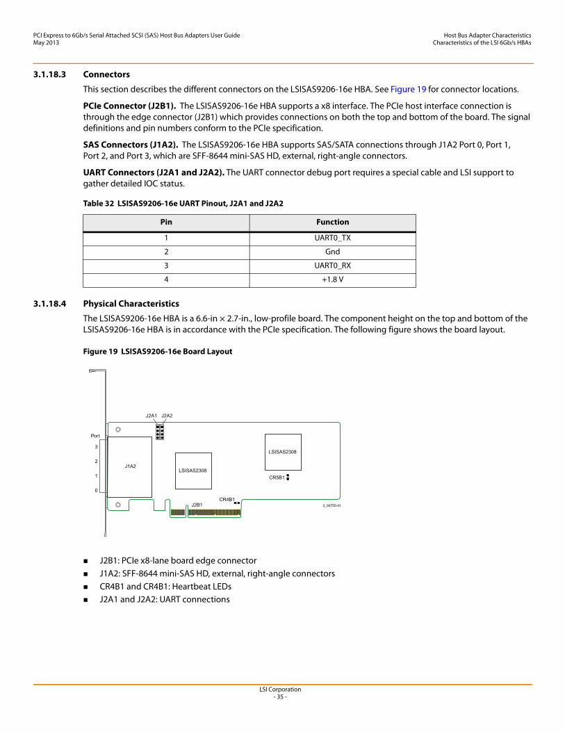
The LSISAS9206-16e HBA is a 6.6-in × 2.7-in., low-profile board. The component height on the top and bottom of the LSISAS9206-16e HBA is in accordance with the PCIe specification. The following figure shows the board layout.
Figure 19 LSISAS9206-16e Board Layout
J2B1: PCIe x8-lane board edge connector J1A2: SFF-8644 mini-SAS HD, external, right-angle connectors CR4B1 and CR4B1: Heartbeat LEDs J2A1 and J2A2: UART connections
Table 32 LSISAS9206-16e UART Pinout, J2A1 and J2A2
Pin Function
1 UART0_TX
2 Gnd
3 UART0_RX
4 +1.8 V

LSI Corporation- 36 -
PCI Express to 6Gb/s Serial Attached SCSI (SAS) Host Bus Adapters User GuideMay 2013
Host Bus Adapter CharacteristicsEnvironmental Specifications
3.2 Environmental Specifications
3.2.1 Power Requirements
The following table lists the maximum power requirements for the LSI 6Gb/s HBAs under normal operation.
Table 33 Maximum Power Requirements
HBA Model PCIe 12.0 V Nominal Power Worst-Case Power Operating Range
LSISAS9200-8e 1.10 A 7.8 W 13.20 W 0 °C to 55 °C
LSISAS9210-8i 1.21 A 7.5 W 14.63 W 0 °C to 55 °C
LSISAS9211-4i 0.96 A 6.3 W 11.51 W 0 °C to 55 °C
LSISAS9211-8i 1.21 A 6.4 W 14.63 W 0 °C to 55 °C
LSISAS9212-4i4e 1.21 A 8.3 W 14.63 W 0 °C to 55 °C
LSISAS9200-16ea 1.67 A 16.2 W 20.00 W 0 °C to 55 °C
LSISAS9200-16e (active) 2.00 A 16.2 W 24.00 W 0 °C to 55 °C
LSISAS9201-16e a 1.74 A 16.7 W 20.94 W 0 °C to 55 °C
LSISAS9201-16e (active) 2.08 A 16.7 W 24.94 W 0 °C to 55 °C
LSISAS9201-16i 2.08 A 15.6 W 24.94 W 0 °C to 55 °C
LSISAS9202-16ea
a. The power-requirements data for this HBA increases if active cables are supported.
2.26 A 16.2 W 27.09 W 0 °C to 55 °C
LSISAS9202-16e (active) 2.26 A 20.2 W 31.09 W 0 °C to 55 °C
LSISAS9205-8e 1.26 A 8.2 W 15.15 W 0 °C to 55 °C
LSISAS9207-8ea 1.30 A 9.8 W 16.00 W 0 °C to 55 °C
LSISAS9207-8e (active) 1.60 A 9.8 W 19.60 W 0 °C to 55 °C
LSISAS9207-8i 1.30 A 9.8 W 16.00 W 0 °C to 55 °C
LSISAS9208-8i 1.30 A 9.8 W 16.00 W 0 °C to 55 °C
LSISAS9207-4i4e 1.30 A 9.8 W 16.00 W 0 °C to 55 °C
LSISAS9217-8i 1.30 A 9.8 W 16.00 W 0 °C to 55 °C
LSISAS9218-8i 1.30 A 9.8 W 16.00 W 0 °C to 55 °C
LSISAS9217-4i4e 1.30 A 9.8 W 16.00 W 0 °C to 55 °C
LSISAS9206-16ea 1.92 Ab
b. PCIe 3.3 V requirement is 0.83 A.
25.8 W — 0 °C to 55 °C
LSI Corporation- 37 -
PCI Express to 6Gb/s Serial Attached SCSI (SAS) Host Bus Adapters User GuideMay 2013
Host Bus Adapter CharacteristicsLSI PCIe-to-SAS HBA Certifications and Safety Characteristics
3.2.2 Thermal and Atmospheric Limits
The atmospheric limits for the LSI 6Gb/s HBAs are as follows:
Temperature range: 0 °C to 55 °C (32 °F to 131 °F) (dry bulb) Relative humidity range: 5 percent to 90 percent noncondensing Maximum dew point temperature: 32 °C (89.6 °F) Minimum airflow: 200 linear feet per minute Minimum airflow for the LSI SAS 9206-16e:
— 100 linear feet per minute at 35 °C (95 °F) bay inlet temperature— 150 linear feet per minute at 45 °C (113 °F) bay inlet temperature— 200 linear feet per minute at 55 °C (131 °F) bay inlet temperature
The following limits define the storage and transit environment for the LSI 6Gb/s HBAs:
Temperature range: 45 °C to +105 °C (–49 °F to +221 °F) (dry bulb) Relative humidity range: 5 percent to 90 percent noncondensing
3.3 LSI PCIe-to-SAS HBA Certifications and Safety Characteristics
All LSI 6Gb/s HBAs meet or exceed the requirements of UL flammability rating 94V-0. Each bare board is marked with the supplier’s name or trademark, type, and UL flammability rating. Because these boards are installed in a PCIe bus slot, all voltages are less than the SELV 42.4-V limit.
The design and implementation of the LSI 6Gb/s HBAs minimizes electromagnetic emissions, susceptibility to radio frequency energy, and the effects of electrostatic discharge.
The LSI 6Gb/s HBAs meet the following integrated electromagnetic interference (EMI) compliance labels:
CE mark CISPR Class B C-Tick mark Canadian Compliance Statement FCC Class B, marked with the FCC Self-Certification logo Japan VCCI Korean KCC Taiwan BSMI
The LSI 6Gb/s HBAs meet the following environmental directives:
RoHS WEEE
NOTE LSI developed airflow limits in a flow tube with ideal airflow. Your server model might require different limits.
LSI Corporation- 38 -
PCI Express to 6Gb/s Serial Attached SCSI (SAS) Host Bus Adapters User GuideMay 2013
Appendix A: HBA Feature Matrix
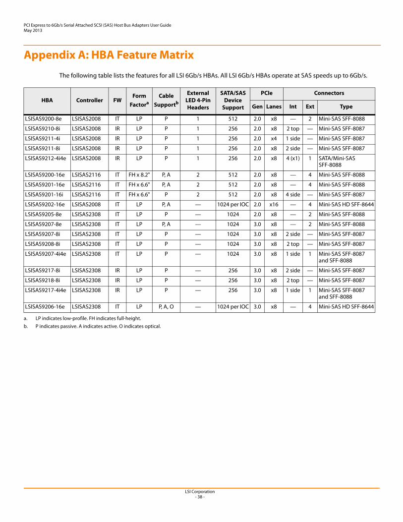
The following table lists the features for all LSI 6Gb/s HBAs. All LSI 6Gb/s HBAs operate at SAS speeds up to 6Gb/s.
HBA Controller FWForm
Factora
a. LP indicates low-profile. FH indicates full-height.
Cable Supportb
b. P indicates passive. A indicates active. O indicates optical.
External LED 4-Pin Headers
SATA/SAS Device
Support
PCIe Connectors
Gen Lanes Int Ext Type
LSISAS9200-8e LSISAS2008 IT LP P 1 512 2.0 x8 — 2 Mini-SAS SFF-8088
LSISAS9210-8i LSISAS2008 IR LP P 1 256 2.0 x8 2 top — Mini-SAS SFF-8087
LSISAS9211-4i LSISAS2008 IR LP P 1 256 2.0 x4 1 side — Mini-SAS SFF-8087
LSISAS9211-8i LSISAS2008 IR LP P 1 256 2.0 x8 2 side — Mini-SAS SFF-8087
LSISAS9212-4i4e LSISAS2008 IR LP P 1 256 2.0 x8 4 (x1) 1 SATA/Mini-SAS SFF-8088
LSISAS9200-16e LSISAS2116 IT FH x 8.2" P, A 2 512 2.0 x8 — 4 Mini-SAS SFF-8088
LSISAS9201-16e LSISAS2116 IT FH x 6.6" P, A 2 512 2.0 x8 — 4 Mini-SAS SFF-8088
LSISAS9201-16i LSISAS2116 IT FH x 6.6" P 2 512 2.0 x8 4 side — Mini-SAS SFF-8087
LSISAS9202-16e LSISAS2008 IT LP P, A — 1024 per IOC 2.0 x16 — 4 Mini-SAS HD SFF-8644
LSISAS9205-8e LSISAS2308 IT LP P — 1024 2.0 x8 — 2 Mini-SAS SFF-8088
LSISAS9207-8e LSISAS2308 IT LP P, A — 1024 3.0 x8 — 2 Mini-SAS SFF-8088
LSISAS9207-8i LSISAS2308 IT LP P — 1024 3.0 x8 2 side — Mini-SAS SFF-8087
LSISAS9208-8i LSISAS2308 IT LP P — 1024 3.0 x8 2 top — Mini-SAS SFF-8087
LSISAS9207-4i4e LSISAS2308 IT LP P — 1024 3.0 x8 1 side 1 Mini-SAS SFF-8087 and SFF-8088
LSISAS9217-8i LSISAS2308 IR LP P — 256 3.0 x8 2 side — Mini-SAS SFF-8087
LSISAS9218-8i LSISAS2308 IR LP P — 256 3.0 x8 2 top — Mini-SAS SFF-8087
LSISAS9217-4i4e LSISAS2308 IR LP P — 256 3.0 x8 1 side 1 Mini-SAS SFF-8087 and SFF-8088
LSISAS9206-16e LSISAS2308 IT LP P, A, O — 1024 per IOC 3.0 x8 — 4 Mini-SAS HD SFF-8644