pavement design guide for subdivision and … version replaces earlier documents designated vhrc...
TRANSCRIPT
VDOT ~ Pavement Design Guide for Subdivision and Secondary Roads in Virginia (revised 2014)
Virginia Department of Transportation
Pavement Design Guide
for
Subdivision
and
Secondary Roads
in Virginia
A companion reference to the Secondary Street Acceptance Requirements
Prepared by
Materials Division
and
Virginia Center for Transportation Innovation and Research
First Printing ~ October 1973
Revised March 1993
Revised January1996
Revised August 2000
Revised July 2009
Revised February 2014
We Keep
Virginia Moving
2
0
1
4
9

VDOT ~ Pavement Design Guide for Subdivision and Secondary Roads in Virginia (revised 2014)
{Page Intentionally Blank}
VDOT ~ Pavement Design Guide for Subdivision and Secondary Roads in Virginia (revised 2014)
Virginia Department of Transportation
Pavement Design Guide
for
Subdivision
and
Secondary Roads
in Virginia
Prepared by
Materials Division
and
Virginia Center for Transportation Innovation and Research
First Printing ~ October 1973
Revised March 1993
Revised January1996
Revised August 2000
Revised July 2009
Revised February 2014

VDOT ~ Pavement Design Guide for Subdivision and Secondary Roads in Virginia (revised 2014)
i
DISCLAIMER
AND
PRECEDENCE OF LOCAL JURISDICTION ORDINANCES
This guide is intended to aid professional personnel knowledgeable in the field of pavement design.
Persons using this guide are responsible for its proper use and application. The Virginia Department of
Transportation and individuals associated with the development of this material cannot be held
responsible for improper use or application.
The design procedures presented in this guide are primarily for flexible pavement to establish minimum
structural requirements. However, acceptable methods are referenced for the design of rigid pavement.
Where the subdivision ordinance of a locality has established a pavement design requirement that exceeds
the pavement design obtained by these procedures, then that design process shall govern. However, these
procedures shall govern the design of pavements for roadways under Department jurisdiction.
ACKNOWLEDGMENTS
This revision was completed by Mohamed Elfino and Affan Habib with input from the District
Materials Engineers, Thomas Tate, Ian Fraser, Mike Wells, Bipad Saha, Bryan Smith and Angela
Beyke.
The encouragement and support of Mr. Charles A. Babish, State Materials Engineer, are greatly
appreciated.
This revision provides the following major items:
1. Separate section for alternate concrete pavement design with traffic up to 400 vehicles per day
incorporating reduced minimum PCC pavement section (7” to 5”) with specific joint details.
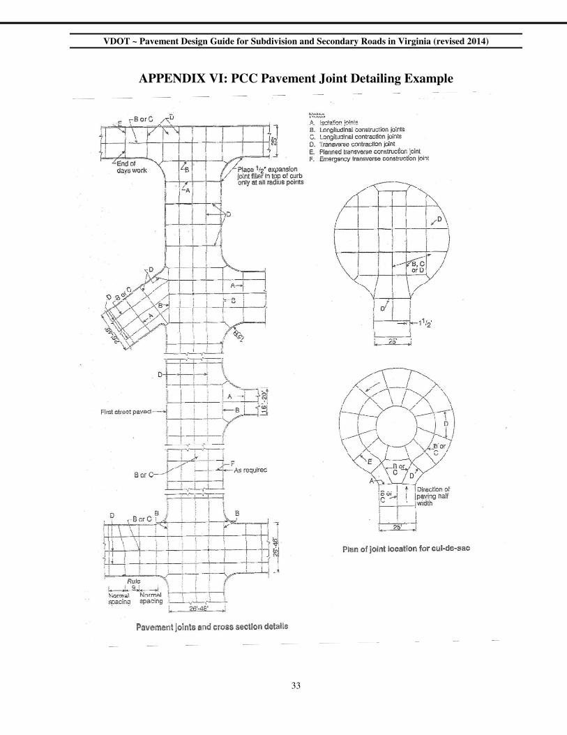
2. Addition of Appendix VI showing PCC pavement joint details example.
3. Clarification on the allowable software for designing rigid pavements.
This version replaces earlier documents designated VHRC 73-R18, VHRC 73-R21, 1993, 1996,
2000, and 2009 for “Pavement Design Guide for Subdivision and Secondary Roads in Virginia”
respectively.

VDOT ~ Pavement Design Guide for Subdivision and Secondary Roads in Virginia (revised 2014)
ii
{Page Intentionally Blank}
VDOT ~ Pavement Design Guide for Subdivision and Secondary Roads in Virginia (revised 2014)
iii
Table of Contents
Introduction 1
Specifications and Additional Resources 1
Computer Software 1
Metric Conversions 1
Discussion of Design Variables 3
Projected Traffic in Terms of Annual Average Daily Traffic (AADT) 3
Soil Support Value (SSV) of the Roadway Subgrade Soil 3
California Bearing Ratio (CBR) of the Roadway Subgrade Soil 3
Test Method 3
Soil Sampling 4
Soil Sample Frequency and CBR Tests for Design of
New Subdivision Streets
4
Soil Sample Frequency and CBR Tests for Design of
Secondary Road Projects
4
Relationship of Design CBR to Number of Tests Performed 4
Construction Factors 5
Resiliency Factor (RF) 5
Discussion of the Flexible Pavement Design Method 7
Thickness Equivalency Value (ax) 7
Thickness Index Value (D) 8
Design Procedures 9
Conventional Pavement Design Method 9
Determination of Design Traffic (Design AADT) 9
Design AADT for New Subdivision Streets 9
Design AADT for Secondary Roads 10
Design AADT When Percent Heavy Commercial Vehicles (%HCV) Exceeds
5.0%
10
Determination of Design CBR, Resiliency Factor (RF), and Soil Support Value (SSV) 11
Determination of Required Thickness Index (DR) 11
Choice of Materials and Pavement Layer Thickness 12
Alternate Pavement Design Method 12

VDOT ~ Pavement Design Guide for Subdivision and Secondary Roads in Virginia (revised 2014)
iv
Table of Contents - continued
Design Considerations 13
Practical Consideration for Thickness of Layers 13
Recommended Minimum and Maximum Limits 13
General Notes and Specifications 14
Subgrade, subgrade treatment or subbase 14
Aggregate Courses 14
Surface Course 15
Minimum Designs (Limited to Secondary Road Projects with AADT ≤ 50) 15
Design Methods for Rigid Pavement 15
Conventional Rigid Pavement Design
Alternate Rigid Pavement Design
15
16
Drainage Considerations for Flexible and Rigid Pavements 17
Index of Appendices
Appendix I Predicted Resiliency Factors, CBR and Soil Support Values 19
Appendix II Nomograph for Determining Required Pavement Thickness Index DR 25
Appendix III Paving Materials and Allowable Values 26
Appendix IV Flexible Pavement Design Worksheet for New Subdivision Streets 28
Appendix V
Appendix VI
Sample Pavement Design
PCC Pavement Joint Detailing Example
30
33
Index of Tables & Figures
Table 1 Classification, Load Support Characteristic, and Resiliency Factor of
Common Soils in Virginia
6
Figure 1 Illustration of 2 and 3 layer pavement systems 7
Figure 2 Illustration of a 3 layer pavement design 8
Index of Equations
Equation 1 SSV = Design CBR x RF 3
Equation 2 DP = a1h1 + a2h2 + a3h3 + … + axhx 8
Equation 3 Design AADT(n) = Present AADT x [1 +(GR)]n 10
Equation 4 EPT = Pres. AADT + (20 x Number of HCV over 5.0%) 10
Equation 5 Design CBR = Average CBR x 2/3 11

VDOT ~ Pavement Design Guide for Subdivision and Secondary Roads in Virginia (revised 2014)
1
Introduction
This guide presents structural design methods for both flexible and rigid pavements intended for new
subdivision streets and secondary roads.
The flexible pavement design method presented in this guide was developed by Dr. N. K. Vaswani, who
based it on the original AASHO Road Test Results of 1962 and reflects Virginia's design experience.
The rigid pavement design methods in this guide utilizes any of the following procedures; AASHTO 93
“Guide for Design of Pavement Structures” and ACPA (current version of StreetPave).
Two design approaches are included in this guide:
A. Conventional Pavement Design Method, which requires a rigorous pavement design procedure.
The conventional flexible pavement design procedure may be divided into two parts:
1. The evaluation of design variables:
a. the traffic in terms of projected Annual Average Daily Traffic (AADT)
b. the soil support value of the subgrade.
2. Design considerations:
a. determination of the required Thickness Index of the pavement
b. the selection of paving materials based on the sum of the products of their
thickness and thickness equivalencies equaling or exceeding the required
Thickness Index value.
B. Alternate Pavement Design Method, which allows the use of predetermined pavement structural
designs for qualifying new subdivision streets.
Specifications And Additional Resources
Specifications for all materials, testing, construction, and installation can be found in the following
Virginia Department of Transportation documents:
• Road and Bridge Specifications and appropriate supplemental specifications
• Virginia Test Methods Manual
• Road and Bridge Standards.
Traffic information for existing VDOT maintained roadways can be obtained at the following internet
link - http://www.virginiadot.org/info/ct-TrafficCounts.asp
• Computer Software
Computer software developed by VDOT can be used for Subdivision and Secondary Roads pavement
design. It is available through the following link ”http://www.virginiadot.org/business/materials-download-
docs.asp” or by contacting the District Materials Engineers.
• Metric Conversions
The following metric conversion factors shall be used throughout this document.
1 inch = 25 mm 1 pound mass = 454 grams
1 foot = 300 mm 1 pound Force = 4.448 Newton
1 mile = 1.6 km 1 pound/in sq. = 6.895 Pascal
VDOT ~ Pavement Design Guide for Subdivision and Secondary Roads in Virginia (revised 2014)
2
{Page Intentionally Blank}
VDOT ~ Pavement Design Guide for Subdivision and Secondary Roads in Virginia (revised 2014)
3
Discussion of Design Variables
Projected Traffic in Terms of Annual Average Daily Traffic (AADT)
The method used to determine the Design AADT varies based on the project considered. Essentially, the
methods are as follows:
A. New Subdivision Streets
The traffic volume for subdivision streets shall be developed as specified in Appendix B (1) of
the Department’s Road Design Manual as referenced by the Secondary Street Acceptance
Requirements (SSAR). The traffic is subject to further adjustment as outlined in the “Flexible
Pavement Design Worksheet for New Subdivision Streets” of Appendix IV of this pavement
design guide.
B. Secondary Roads
Pavement design for existing Secondary Roads shall be based on the projected traffic volume for
the midpoint of the 20 year design period (i.e. 10 years) after completion of roadway
construction. A more complete discussion regarding this factor is found under the section “Design
Procedures.”
Soil Support Value (SSV) of the Roadway Subgrade Soil
The Soil Support Value of the subgrade soil is the product of the Design CBR and the soil Resiliency
Factor for the soil encountered, as expressed in Equation 1. SSV is used in conjunction with the design
traffic volume (Design AADT) to determine the minimum structure requirement (Required Thickness
Index) for the pavement.
SSV = Design CBR x RF Equation 1
Note: Subgrade soils that are very weak or have a very low resiliency factor
(i.e. SSV ≤ 2) should be stabilized or under cut.
A. California Bearing Ratio (CBR) of the Roadway Subgrade Soil
The California Bearing Ratio (CBR) is the ratio of the resistance to penetration exhibited by a
subgrade soil to that exhibited by a specimen of standard crushed stone base material. The
resistance of the crushed stone under standardized conditions is well established. The objective of
a CBR test is to determine the relative resistance of the subgrade material under the same
conditions.
The CBR of the subgrade soils is the principle component of the soil support value (SSV) used in
flexible pavement design to determine the required pavement thickness index.
1. Test Method
All CBR values are to be determined in accordance with "The Virginia Test Method for
Conducting California Bearing Ratio Tests" (Designation VTM-8). For each roadway, a
sufficient number of CBR tests must be conducted to determine the average CBR value for
the various soil types anticipated to be in the subgrade.

VDOT ~ Pavement Design Guide for Subdivision and Secondary Roads in Virginia (revised 2014)
4
2. Soil Sampling
Representative soil samples for CBR tests shall be taken from the top 12 inches of
the proposed grade by a qualified soils technician or engineer. If the subgrade soil
has been identified as fine grained (i.e. more than 35% passing the 200 sieve
according to AASHTO Classification System), Atterberg tests (Liquid and Plastic
limits) shall be run in addition to the normal sieve analysis, laboratory compaction
and CBR tests, so that an assessment of the potential need for subgrade stabilization
or undercut can be made. If indications of unstable conditions for construction
equipment are present, natural moisture content determinations should also be made
to aid in determining the appropriate method of stabilization/undercut by
comparison with the Atterberg Limits of the soils.
a. Soil Sample Frequency and CBR Tests for Design of New
Subdivision Streets
1) For streets less than 200 feet in length, one soil sample for
conducting AASHTO (AASHTO M 145) and Unified (ASTM D
2488) soil classifications and CBR test is required.
2) For streets 200 to 500 feet in length, at least two soil samples for
conducting AASHTO and Unified soil classifications and CBR
tests is required, which includes one at each intersection with an
existing state road.
3) For longer streets, one soil sample shall be taken at each
intersection with an existing state road plus one test sample every
500 feet in length, or portion thereof, is required for conducting
AASHTO and Unified soil classifications and CBR tests.
b. Soil Sample Frequency and CBR Tests for Design of Secondary Road
Projects
The District Materials Engineer should assure that sufficient CBR tests are
made to represent the various soils encountered on the project. This is to
assure that a reasonable estimate of the average subgrade CBR is
determined. The frequency of soil samples for secondary road projects will
be determined by the District Materials Engineer under the general
guidance of the Materials Division Manual of Instructions.
3. Relationship of Design CBR to Number of Tests Performed
Design CBR is a factor of the number of CBR test results available.
a. For five tests or less, the design CBR shall be the mathematical
average of these tests multiplied by two-thirds, rejecting any
obviously extreme value.
b. For more than five tests, the highest and lowest CBR values are
rejected and the Design CBR value shall be the mathematical
average of the remaining CBR test values multiplied by a factor of
two-thirds.
VDOT ~ Pavement Design Guide for Subdivision and Secondary Roads in Virginia (revised 2014)
5
The two-thirds factor provides the necessary safety margin to compensate
for any non-uniformity of the soil, and for any low test results not
considered when computing the average of the CBR sample values.
Furthermore, four days of soaking, as specified in the CBR test method,
does not necessarily give the minimum CBR strength of some soils. Thus,
the two-thirds factor would compensate for all such variations.
4. Construction Factors
The design CBR determination process assumes that the properly compacted subgrade soil
will produce a stable platform for pavement construction. If an unstable subgrade is
encountered, it should be undercut to a firm foundation and be replaced with adequately
compacted soil or aggregate materials or otherwise be stabilized by lime, cement, or the use
of a geotextile to produce a stable platform for construction equipment.
Subgrade compaction should be verified every 1000 feet before placement of the
subbase/base layer, with a minimum of two compaction tests per roadway. The compaction
shall be 100 percent of standard proctor (VTM-1) for all but gravely soils. Refer to Section
305.03 of The Road and Bridge Specification for compaction requirements for gravely
soils.
B. Resiliency Factor (RF)
1. When soil is repeatedly loaded, it undergoes both recoverable (elastic) and permanent
(plastic) deformation. The Resiliency Factor is a relative value that reflects a soil’s elastic
deformation characteristics and its ability to withstand repeated loading.
2. The smaller the elastic deformation the higher the degree of resiliency, and the better the
subgrade support. The subgrade soils in Virginia are divided into five load support
characteristics based on their degree of resiliency (see Table 1). The resiliency factor of a
given soil can be obtained most precisely if the soil classification is known.
Predicted regional resiliency factors are shown in Appendix I. These factors are valid
only when the in-situ moisture content of the subgrade soil is at or near optimum
moisture content.
The optimum moisture content is determined by AASHTO Test Method T 99, Method A,
as modified by VTM-1. Additional moisture content testing should be conducted during
construction if visual observations dictate. Soils with a moisture content of 20 percent
above optimum may need special treatment or may need to be undercut and replaced.
3. Evaluation of Soil Resiliency Factors
Three primary factors are considered in the evaluation of Soil Resiliency Factors:
a. Soil Classification (based on AASHTO M- 145)
b. Sand content (percent retained on No. 200 sieve)
c. Mica content

VDOT ~ Pavement Design Guide for Subdivision and Secondary Roads in Virginia (revised 2014)
6
Determination of the mica content is to be done by visual observations.
Borderline cases of low or high mica content shall be decided by the District
Materials Engineer of the Virginia Department of Transportation.
Use Table 1 to determine the soil resiliency factor, proceeding from the top to the
bottom and obtain the correct resiliency factor by the process of elimination.
Table 1
Classification, Load Support Characteristic, and Resiliency Factor
of
Common Soils in Virginia
Mica
Content Soil Classification
Load
Support
Characteristic
Resiliency
Factor
Without
Mica
a) A-1 & A-3 Soils
b) A-4, A-5 and A-7 soils having a sand content greater
than 60% Excellent 3.0
A-2, A-4, A-5, A-6 and A-7 soils having a sand content
between 40% and 60%. Good 2.5
A-2, A-4, A-5, A-6 and A-7 soils having a sand content
less than 40% Average 2.0
a) A-7-5 soil.
1.5
With Mica
b) soil with low or trace mica content and having an
average group index (GI) below 5 Poor
c) A-2, A-5, A-6, and A-7-6 soils with low or trace mica
content
Soils not within the category of Medium Low Resiliency
Soils and also contain mica. Very Poor 1.0
VDOT ~ Pavement Design Guide for Subdivision and Secondary Roads in Virginia (revised 2014)
7
Discussion of the Flexible Pavement Design Method
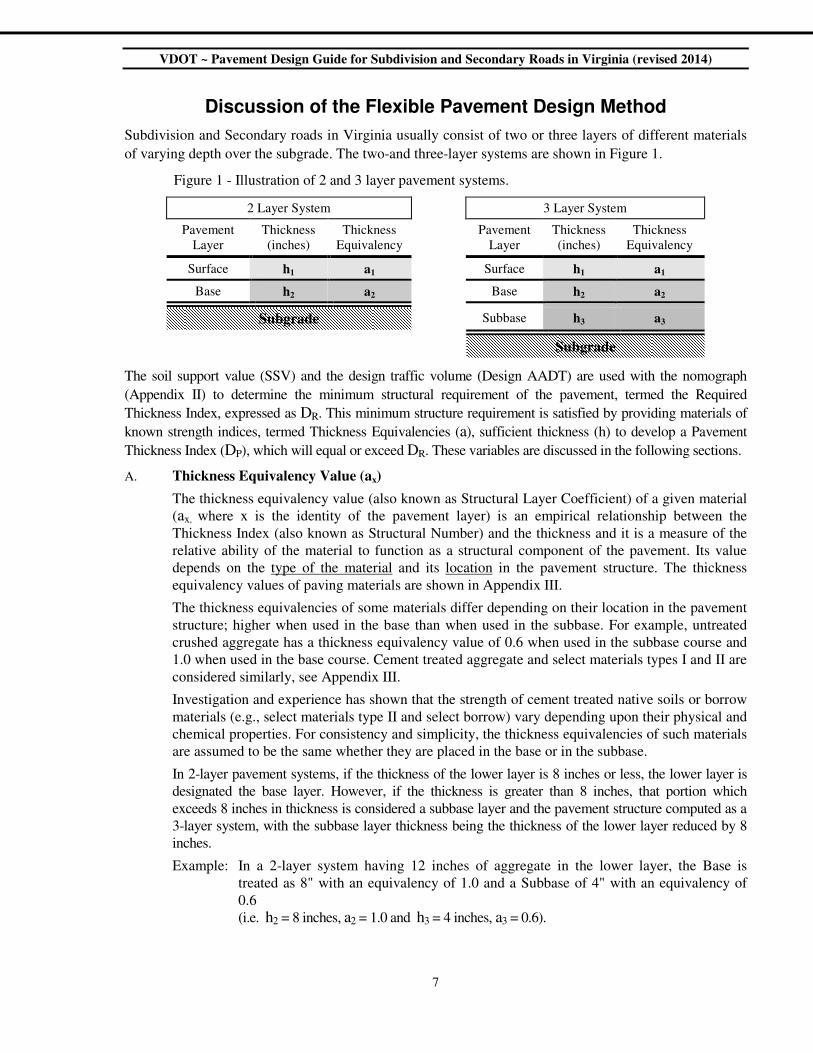
Subdivision and Secondary roads in Virginia usually consist of two or three layers of different materials
of varying depth over the subgrade. The two-and three-layer systems are shown in Figure 1.
Figure 1 - Illustration of 2 and 3 layer pavement systems.
2 Layer System 3 Layer System
Pavement
Layer
Thickness
(inches)
Thickness
Equivalency
Pavement
Layer
Thickness
(inches)
Thickness
Equivalency
Surface h1 a1 Surface h1 a1
Base h2 a2 Base h2 a2
Subgrade Subbase h3 a3
Subgrade
The soil support value (SSV) and the design traffic volume (Design AADT) are used with the nomograph
(Appendix II) to determine the minimum structural requirement of the pavement, termed the Required
Thickness Index, expressed as DR. This minimum structure requirement is satisfied by providing materials of
known strength indices, termed Thickness Equivalencies (a), sufficient thickness (h) to develop a Pavement
Thickness Index (DP), which will equal or exceed DR. These variables are discussed in the following sections.
A. Thickness Equivalency Value (ax)
The thickness equivalency value (also known as Structural Layer Coefficient) of a given material
(ax, where x is the identity of the pavement layer) is an empirical relationship between the
Thickness Index (also known as Structural Number) and the thickness and it is a measure of the
relative ability of the material to function as a structural component of the pavement. Its value
depends on the type of the material and its location in the pavement structure. The thickness
equivalency values of paving materials are shown in Appendix III.
The thickness equivalencies of some materials differ depending on their location in the pavement
structure; higher when used in the base than when used in the subbase. For example, untreated
crushed aggregate has a thickness equivalency value of 0.6 when used in the subbase course and
1.0 when used in the base course. Cement treated aggregate and select materials types I and II are
considered similarly, see Appendix III.
Investigation and experience has shown that the strength of cement treated native soils or borrow
materials (e.g., select materials type II and select borrow) vary depending upon their physical and
chemical properties. For consistency and simplicity, the thickness equivalencies of such materials
are assumed to be the same whether they are placed in the base or in the subbase.
In 2-layer pavement systems, if the thickness of the lower layer is 8 inches or less, the lower layer is
designated the base layer. However, if the thickness is greater than 8 inches, that portion which
exceeds 8 inches in thickness is considered a subbase layer and the pavement structure computed as a
3-layer system, with the subbase layer thickness being the thickness of the lower layer reduced by 8
inches.
Example: In a 2-layer system having 12 inches of aggregate in the lower layer, the Base is
treated as 8" with an equivalency of 1.0 and a Subbase of 4" with an equivalency of
0.6
(i.e. h2 = 8 inches, a2 = 1.0 and h3 = 4 inches, a3 = 0.6).

VDOT ~ Pavement Design Guide for Subdivision and Secondary Roads in Virginia (revised 2014)
8
The thickness equivalency values of new paving materials must be evaluated relative to
established thickness equivalencies as each material is introduced.
B. Thickness Index Value (D)
The Thickness Index (D) is the total structure of the pavement based on its resistance to a
deflection caused by a wheel load. The minimum thickness index required, based on the SSV of
the subgrade and design traffic volume (Design AADT) is denoted with the symbol DR and is
obtained from the nomograph (Appendix II). The thickness index value of a pavement design is
denoted by the symbol DP and is obtained by Equation 2 below. A potentially acceptable
pavement design is derived when DP equals or exceeds DR (i.e. DP ≥ DR).
DP = a1h1 + a2h2 + a3h3 + … + axhx Equation 2
Where: a1, a2, and a3 are the thickness equivalencies of the surface, base and subbase layers, and h1, h2, and h3 represent the thickness in inches of the surface, base, and subbase layers, respectively. In
the case of a two-layer system a subbase may not be provided; in this instance, a3h3 = 0.
Figure 2 - Illustration of a 3-layer pavement design using values from Appendix III in Equation 2.
Pavement
Layer Material
Thickness
inches
(hx)
Thickness
Equivalency
Value
(ax)
(hx) X (ax)
Surface 165 P/SY Asphalt Concrete SM-9.5A 1.5 2.25 1 3.38
Base 3” Asphalt Concrete BM-25.0A 3.0 2.25 6.75
Subbase Untreated Aggregate (21B) 6.0 0.60 3.6
S u b g r a d e DP = a1h1 + a2h2 + a3h3 = 13.73
1 Note: The higher thickness equivalency value is used for the surface and base material because the
combined thickness of the asphalt concrete equals 4.5 inches. Refer to footnote, Appendix III
VDOT ~ Pavement Design Guide for Subdivision and Secondary Roads in Virginia (revised 2014)
9
Design Procedures
New subdivision street pavement designs are to be developed using the “Flexible Pavement Design
Worksheet for New Subdivision Streets” (Appendix IV), which the developer shall submit with the
design documents for each new subdivision street. Certain new subdivision streets (with a low traffic
volume) may qualify to use the Alternate Pavement Design Method.
Pavement designs for secondary road projects, including developer projects augmenting, realigning, or
relocating secondary roads, are to be developed using the Conventional Pavement Design Method.
Conventional Pavement Design Method
A. Determination of Design Traffic (Design AADT)
The Design AADT used to determine DR from the nomograph in Appendix II, assumes the traffic
volume is equally distributed in both directions. In addition the lane distribution shall be
considered as follows:
a. For all new subdivision streets and two-lane secondary road facilities (one lane in
each direction), including the initial two lane phase of a four lane facility when
that phase is expected to sustain two-way traffic for an appreciable length of
time; the Design AADT shall be the full traffic volume of the roadway.
b. The Design AADT for multi lane facilities, except as restricted in paragraph a,
shall be 80% of the full roadway traffic volume for 4-lanes (two lanes in each
direction) and 70% for 6-lane facilities.
For traffic volumes exceeding 10,000 AADT, the actual truck count and classification needs to be
determined and serious consideration shall be given to designing the pavement as a primary road
facility rather than as a secondary road or new subdivision street. A truck equivalency factor may
be used to convert the truck traffic to an 18 Kip Equivalent Single Axle Load (ESAL), using 0.46
for each single unit truck and 1.05 for each tractor trailer truck. Designers should check with the
District Materials Engineers for updated equivalency factors.
Once the ESAL's are available, the pavement can be designed using the “1993 AASHTO Guide
for Design of Pavement Structures” in conjunction with the Department’s Materials Division
Manual of Instruction Chapter VI.
1. Design AADT for New Subdivision Streets
Design AADT for new subdivision streets shall be determined as described in the current
edition of Appendix B (1) of the Department’s Road Design Manual, subject to any
adjustment as may be indicated in Step 1 of the “Flexible Pavement Design Worksheet
for New Subdivision Streets” (Appendix IV) and as further explained in paragraph 3,
“Design AADT When Percent Heavy Commercial Vehicles (%HCV) Exceeds 5.0%.”
Therein, the term ‘present traffic’ shall be synonymous with the term ‘projected traffic’
when new subdivision streets are considered.

VDOT ~ Pavement Design Guide for Subdivision and Secondary Roads in Virginia (revised 2014)
10
2. Design AADT for Secondary Roads
The Design AADT for an improvement to the secondary roads system shall be
determined by Equation 3:
Design AADT (n) = Present AADT x [1 +(GR.)]n Equation 3
Where: Design AADT is the Annual Average Daily Traffic volume
projected for the design year (typically the 10th year after construction is
complete) and “n” is the number of years between the design year and
the year of the present traffic volume (AADT).
The Present AADT is the current traffic volume (AADT) in both
directions, determined from an actual traffic count or from preliminary
engineering estimates, provided/approved by VDOT's Traffic
Engineering or Transportation Planning Divisions.
GR. is the Growth Rate percentage expressed as a decimal
(i.e. 5% GR. = 0.05), which may be based on actual historical traffic data
or from estimates made by Traffic Engineering Division. The expression
[1 + (GR.)]n yields the "Growth Factor" based on the anticipated annual
rate of growth of traffic.
Example: If the Present AADT = 700 for Year 2009, the GR. = 3.6%, and
the Roadway Construction is to be completed in Year 2012.
Then: 10th Year after Construction = 2012 + 10 = 2022;
Thus, n = 2022 - 2009 = 13 and Equation 3 yields:
Design AADT13 = 700 x [1 + (0.036)]13
= 700 x (1.036)13
= 700 x (1.584) = 1109 AADT in Year 2022
3. Design AADT When Percent Heavy Commercial Vehicles (%HCV) Exceeds 5.0%
The nomograph in Appendix II assumes the number of Heavy Commercial Vehicles
(HCV), defined as trucks, buses, etc., having 2 or more axles and 6 or more tires, does
not exceed 5.0% of the total traffic volume (AADT). When the design traffic volume
includes more than 5.0% HCV, each heavy commercial vehicle above the 5.0% level is
considered equal to twenty (20) typical (i.e. non-HCV) vehicles. An Equivalent Present
Traffic volume (EPT) representing this adjustment is calculated by Equation 4, the results
of which are to be substituted for the Present AADT value used in Equation 3.
EPT = Pres. AADT + (20 x Number of HCV over 5.0%) Equation 4
{Note: Number of HCVs over 5.0% = (% HCV - 5.0%) x Present AADT,
where (% HCV - 5.0%) is expressed as a decimal}
Example: If Present Traffic Volume = 1000 AADT, Percent Trucks = 8 %
Using Equation 4:
EPT = 1000 + {20 x [1000 x (0.08-0.05)]}
= 1000 + [20 x (1000 x 0.03)]
= 1000 + (20 x 30)
= 1000 + 600 = 1600 AADT
VDOT ~ Pavement Design Guide for Subdivision and Secondary Roads in Virginia (revised 2014)
11
B. Determination of Design CBR, Resiliency Factor (RF), and
Soil Support Value (SSV)
1. The Design CBR, as discussed earlier, is the product of the average values of the CBR
test results and a safety factor of 2/3, expressed as Equation 5.
Design CBR = Average CBR x 2/3 Equation 5
2. Determination of Resiliency Factor (RF)
The Resiliency Factor (RF) may be determined by one of the following methods:
a. Table 1
b. Appendix I - Predicted Regional Resiliency Factors, which are shown graphically for the state and in a listing by county. These values are to be considered maximum values unless otherwise approved by the District Materials Engineer.
c. Obtained from the District Materials Engineer.
3. Determination of Soil Support Value (SSV)
The Soil Support Value (SSV) is the product of the Design CBR and RF, as expressed in
Equation 1 (SSV = Design CBR x RF), and has a maximum value of 30.
4. Preliminary pavement designs may use the predicted SSV values from Appendix I.
However, when the soil moisture content exceeds the plastic limit, and approaches the
liquid limit, the predicted values in Appendix I should not be used and a maximum SSV
of 2 should be used. Pavement designs for new subdivision streets shall be considered
preliminary designs, not approved for construction, until substantiated by acceptable
test results of the subgrade soil. Approval of the final design shall be obtained prior to
construction of the pavement.
5. Even if lime or cement stabilization of the roadway subgrade is to be considered, the Soil
Support Value is based on tests of the non-stabilized soils. Only in the rare case where
multiple layers are stabilized for a total stabilized depth of 2 feet or more may the SSV be
based on tests of the stabilized soil.
6. Where undercutting and backfilling with dense graded aggregate material or unusually
high CBR native soil material is necessary to provide a stable construction platform, the
Soil Support Value is still to be based on the native soil test results. The only exception
to this would be if the entire roadway subgrade is undercut and backfilled to a minimum
depth of 2 feet.
C. Determination of Required Thickness Index (DR)
The required thickness index (DR) is determined from the nomograph in Appendix II, by
projecting a straight line from the Soil Support Value (SSV), through the Design AADT value, to
intersect the Required Thickness Index scale, from which the minimum required Thickness Index
(DR) is read. Alternately, computer software developed by VDOT can be used for pavement
design. It is available through the following link ”http://www.virginiadot.org/business/materials-
download-docs.asp” or by contacting the District Materials Engineers.
VDOT ~ Pavement Design Guide for Subdivision and Secondary Roads in Virginia (revised 2014)
12
D. Choice of Materials and Pavement Layer Thickness
After DR is determined, the pavement structure design can be derived, as earlier discussed and
illustrated in Figure 2, subject to the factors discussed in the sections “Design Considerations”
and “Drainage Considerations for Flexible and Rigid Pavements.”
Alternate Pavement Design Method
Acceptable, flexible pavement designs for low traffic volume (Design AADT ≤ 400) new subdivision
streets are shown in Appendix IV (Tables A and B). These predetermined pavement designs may only be
used in conjunction with the “Flexible Pavement Design Worksheet for New Subdivision Streets” (Step
3A) provided in Appendix IV. Acceptable rigid pavement designs for low volume (Design AADT ≤ 400)
new subdivisions are presented on page 16.
For new subdivision streets and secondary road projects having a Design AADT greater than 400,
pavement designs must be determined using the Conventional Pavement Design Method, which is
accommodated in Step 3B of the “Flexible Pavement Design Worksheet for New Subdivision Streets.”

VDOT ~ Pavement Design Guide for Subdivision and Secondary Roads in Virginia (revised 2014)
13
DESIGN CONSIDERATIONS
After the Required Thickness Index (DR) of the pavement has been determined, the choice of materials
and the thickness of the layers for the pavement design are primarily at the discretion of the pavement
designer. These decisions are usually based on dollar value, structural adequacy, pavement serviceability,
historical data, experience, availability of materials, ease of construction, maintenance of traffic, etc.
A. Practical Consideration for Thickness of Layers
The thickness of layers is related to practical considerations. The following are some of the
physical characteristics of materials to be considered:
1. The maximum obtainable density of aggregates and asphalt concretes.
2. The stability of asphalt concrete mixes.
3. The preparation of the subgrade (by providing a stabilized subgrade layer).
4. The weakness of thin layers of fairly rigid materials like asphalt concrete, and stabilized
soil layers.
5. Nominal aggregate size of the asphalt mix.
B. Recommended Minimum and Maximum Limits
The recommended minimum and maximum limits for the thickness of pavement layers are shown
in Appendix III, however, not less than 4.5 inches of asphalt concrete must be placed over cement
treated base/subbase material (CTA) as the surface/intermediate/base layer(s). In addition, the
following criteria shall be considered:
1. Maximum thickness of an asphalt concrete surface shall be 2 inches, except as follows:
a. When staged surfacing is required, a maximum of 2½ inches of surface is
allowable, provided the thickness of the final layer is not less than one inch and
at least one year’s time elapses between the placement of the initial and final
surfaces.
b. A maximum thickness of 3 inches is allowable when using Type IM-19.0A.
c. Six inches of full-depth asphalt concrete pavement is the minimum recommended
allowable thickness (surface mix and base mix) when placed directly on the
prepared subgrade, except as may be permitted by Tables A and B in Appendix
IV for qualifying new subdivision streets.
2. The maximum thickness of aggregate material used as the base layer shall be 8 inches
before considering any additional thickness as a subbase material.
3. Maximum combined thickness of the base and subbase aggregate layers is 12 inches.

VDOT ~ Pavement Design Guide for Subdivision and Secondary Roads in Virginia (revised 2014)
14
General Notes and Specifications
All full lane widening projects shall be in accordance with VDOT WP-2 standard
The following recommendations are based on the Department’s design and construction experience:
A. Subgrade, Subgrade Treatment, or Subbase
1. The preparation of the subgrade should be in accordance with the current Virginia
Department of Transportation's Road and Bridge Specifications.
2. Local materials, free of organic matter that normally would be considered unsatisfactory
for use in construction, may be acceptable when stabilized with a stabilizing agent, such
as cement or lime. Lime or cement stabilized subgrades provide a sound foundation that
is a good investment when the traffic is likely to increase considerably. Additionally, this
practice may prove to be the most economical.
3. For soils having a high moisture content, treatment with lime or other pozzolanic material
(1% to 2% by weight), in lieu of undercutting, may be appropriate. However, such lime
treatment is not to be considered part of the pavement structure in calculating the
Thickness Index.
4. When cement stabilized subgrade is recommended, approximately 10% by volume
should be used. When lime is the subgrade stabilizing agent, approximately 5% by
weight should be used. If Select Material, Type II is used, cement stabilization is
required. In all cases, representative samples of the soil should be tested in accordance
with VTM-72 (for Cement) and VTM-11 (for Lime) to determine the optimal percentage.
If soil stabilization (cement or lime) is used, verification of the quantity of stabilizing
agent actually used will be required through the District Materials Engineer.
5. When cement stabilized aggregate is used over very weak soils (SSV ≤ 2), it should be
placed over a minimum of 4 inches of untreated aggregate.
6. Soil stabilization should be completed before the temperature drops below 40 degrees
Fahrenheit and, for best results, covered immediately with an untreated aggregate course
(provided that construction equipment does not damage the stabilized course) or an
asphalt seal.
7. Geotextile should be considered for subgrade stabilization, when the areas in question
represent a relatively small amount of the subgrade soils. This may prove more
economically feasible, in isolated cases, than the Alternates discussed above. Refer to
VDOT Road & Bridge Specifications regarding geosynthetics for subgrade stabilization
to select the proper strength requirements.
B. Aggregate Courses
1. Aggregate Base Materials are of two types and various sizes as shown below:
a. Type I - Aggregate base material (crushed material only) using size No. 21A, No.
21B or No. 22 aggregate. The coarser graded aggregate Size No. 21 B is
preferred for AADT over 1000.
b. Type II Aggregate base material (crushed or uncrushed material) using No. 21A,
or No. 22 size aggregate.

VDOT ~ Pavement Design Guide for Subdivision and Secondary Roads in Virginia (revised 2014)
15
2. All untreated aggregate used in base or subbase courses shall be No. 21B gradation,
except on roads with an ADT of 1000 or less; where No. 21A or No. 21B may be used.
When the No. 21B gradation is used, drainage concerns must be addressed. Use No. 21A
gradation if the aggregate is cement stabilized (i.e. CTA).
3. When a local aggregate material is stabilized with cement, approximately 8% by volume
should be used. When lime is used as the stabilizing agent, approximately 4% by weight
should be used.
In all cases, however, representative samples of the material should be tested to
determine the correct percentage of stabilizing agent. A minimum stabilized depth of 6
inches is required.
4. When cement treated aggregate (CTA) is proposed for use a minimum of 4.5 inches of
asphalt concrete should be used atop the CTA in order to retard reflection of the
shrinkage cracks from the CTA.
C. Surface Course
An asphalt concrete surface course of 220 pounds per square yard (2 inches thick), may be used
in lieu of a Class "C" or Class "D" blotted seal or a prime and double seal surface treatment (as
specified in all current L&D I&I memoranda).
D. Minimum Designs (Limited to Secondary Road Improvement Projects with AADT ≤ 50)
1. The base should consist of a minimum of 6 inches aggregate base material, Types I or II,
yielding a thickness index of 6.
2. The following minimum recommended design shall only be used when the road is to be
surface treated.
As an Alternate, in areas containing borderline local materials but not meeting the
specifications for Type I or II base materials, the base may consist of a minimum depth of
6 inches of select borrow having a minimum CBR value of 20. The select borrow base
should be stabilized with cement, 8% to 10% by volume, or approximately 40 pounds of
cement per square yard. The cement stabilized borrow should be surfaced with a curing
agent and double seal. In all cases, however, representative samples of the material
should be tested to determine the correct percentage of stabilizing agent.
DESIGN METHODS FOR RIGID PAVEMENT
Conventional Rigid Pavement Design
The following rigid pavement design methods are acceptable: ACPA (current version of StreetPave ) and
1993 AASHTO Guide for Design of Pavement Structures using a minimum of 5% truck traffic or the
actual truck traffic (whichever is higher). The thickness shall be rounded up to the nearest 0.5 inches.
Concrete shall be Class A-3 paving concrete according to the current Virginia Department of
Transportation’s Road and Bridge Specifications and appropriate supplemental specifications. The
pavement shall be Plain Jointed Portland Cement Concrete with a designed transverse joint spacing not to
exceed 15 feet (the joint spacing in feet shall not exceed 2 times the pavement thickness in inches). Non
dowelled pavement 6” or less in thickness, shall have at least 3 longitudinal joints (no joint along the
wheel path), shall have maximum aspect ratio of 1:1 (length to width) and shall have maximum panel size
of 8’ by 8’. Some typical joint detail examples are provided in Append VI. Continuously Reinforced
VDOT ~ Pavement Design Guide for Subdivision and Secondary Roads in Virginia (revised 2014)
16
Concrete Pavement may be considered an acceptable option. In the case of very weak or very low
resiliency soils having CBR values less than 2, the soil should be stabilized for a depth of six (6) inches
with cement, 10% - 12% by volume, or in accordance with a detailed geotechnical design which the
developer shall submit with the design documents for each new subdivision street.
Alternate Rigid Pavement Design
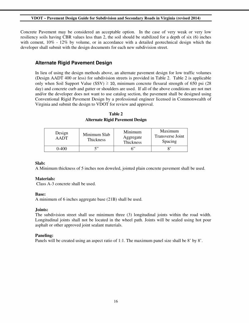
In lieu of using the design methods above, an alternate pavement design for low traffic volumes
(Design AADT 400 or less) for subdivision streets is provided in Table 2. Table 2 is applicable
only when Soil Support Value (SSV) ≥ 10, minimum concrete flexural strength of 650 psi (28
day) and concrete curb and gutter or shoulders are used. If all of the above conditions are not met
and/or the developer does not want to use catalog section, the pavement shall be designed using
Conventional Rigid Pavement Design by a professional engineer licensed in Commonwealth of
Virginia and submit the design to VDOT for review and approval.
Table 2
Alternate Rigid Pavement Design
Design
AADT
Minimum Slab
Thickness
Minimum
Aggregate
Thickness
Maximum
Transverse Joint
Spacing
0-400 5” 6” 8’
Slab:
A Minimum thickness of 5 inches non doweled, jointed plain concrete pavement shall be used.
Materials: Class A-3 concrete shall be used.
Base: A minimum of 6 inches aggregate base (21B) shall be used.
Joints: The subdivision street shall use minimum three (3) longitudinal joints within the road width.
Longitudinal joints shall not be located in the wheel path. Joints will be sealed using hot pour
asphalt or other approved joint sealant materials.
Paneling: Panels will be created using an aspect ratio of 1:1. The maximum panel size shall be 8’ by 8’.
VDOT ~ Pavement Design Guide for Subdivision and Secondary Roads in Virginia (revised 2014)
17
DRAINAGE CONSIDERATIONS FOR FLEXIBLE AND RIGID PAVEMENTS
The presence of water within the pavement structure has a detrimental effect on pavement performance
under anticipated traffic loads. The following are guidelines to minimize these effects:
a) Standard UD-2 underdrains and outlets are required under all raised grass medians to prevent
water infiltration through or under the pavement structure. Refer to the current VDOT Road
and Bridge Standards for installation details.
b) When Aggregate Base Material, Type I, Size No. 21B is used as an untreated aggregate base
or subbase, it shall be connected to a longitudinal pavement edge drain (UD-4) with outlets to
provide for positive lateral drainage on all roadways with a design AADT of 1,000 vehicles
per day or greater. (Refer to the current VDOT Road and Bridge Standards for installation
details). The District Materials Engineers may waive the requirement for UD-4 installation in
special instances, providing another means of pavement drainage such as cross drains or
“daylighting” of the subbase course is used. Other drainage layers can also be used.
c) Undercutting, transverse drains, stabilization, and special design surface and subsurface
drainage installations should be considered whenever necessary to minimize the adverse
impacts of subsurface water on the stability and strength of the pavement structure.
d) Standard CD-1 and CD-2 for cut to fill and vertical sags respectively should be considered for
use with all types of unstabilized aggregates.
e) For roadways with a design AADT of 20,000 vehicles per day or greater, an Open Graded
Drainage Layer (OGDL) need to be considered, and when used it shall be placed on not less
than 6-inches of stabilized material and connected to a UD-4 edge drain system.
f) Where cement treated aggregate (CTA) is the only aggregate used in a pavement structure,
UD-4 pavement edge drains are not normally required.
For additional information see Report Number FHWA-TS-80-224, Highway Sub-drainage Design from
the US Department of Transportation, Federal Highway Administration.

VDOT ~ Pavement Design Guide for Subdivision and Secondary Roads in Virginia (revised 2014)
18
{Page Intentionally Blank}
VDOT ~ Pavement Design Guide for Subdivision and Secondary Roads in Virginia (revised 2014)
19
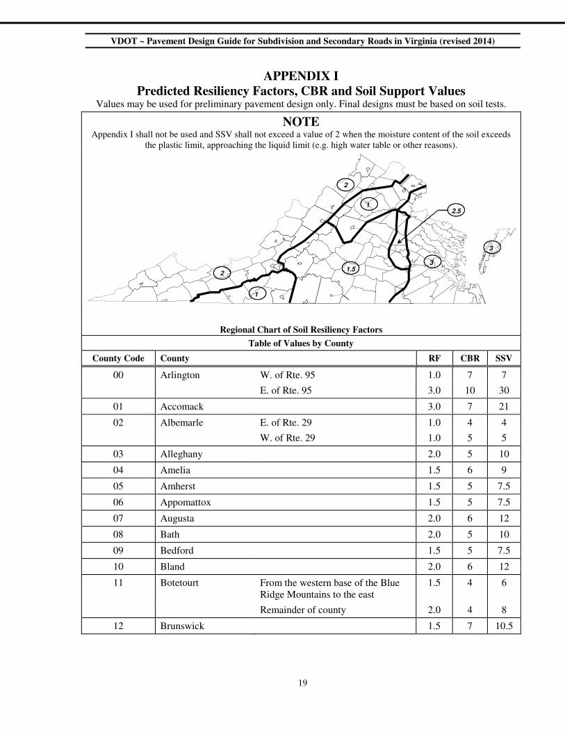
APPENDIX I
Predicted Resiliency Factors, CBR and Soil Support Values Values may be used for preliminary pavement design only. Final designs must be based on soil tests.
NOTE Appendix I shall not be used and SSV shall not exceed a value of 2 when the moisture content of the soil exceeds
the plastic limit, approaching the liquid limit (e.g. high water table or other reasons).
Regional Chart of Soil Resiliency Factors
Table of Values by County
County Code County RF CBR SSV
00 Arlington W. of Rte. 95 1.0 7 7
E. of Rte. 95 3.0 10 30
01 Accomack 3.0 7 21
02 Albemarle E. of Rte. 29 1.0 4 4
W. of Rte. 29 1.0 5 5
03 Alleghany 2.0 5 10
04 Amelia 1.5 6 9
05 Amherst 1.5 5 7.5
06 Appomattox 1.5 5 7.5
07 Augusta 2.0 6 12
08 Bath 2.0 5 10
09 Bedford 1.5 5 7.5
10 Bland 2.0 6 12
11 Botetourt From the western base of the Blue
Ridge Mountains to the east
1.5 4 6
Remainder of county 2.0 4 8
12 Brunswick 1.5 7 10.5
1
1.52
2.5
3
1
2
3
VDOT ~ Pavement Design Guide for Subdivision and Secondary Roads in Virginia (revised 2014)
20
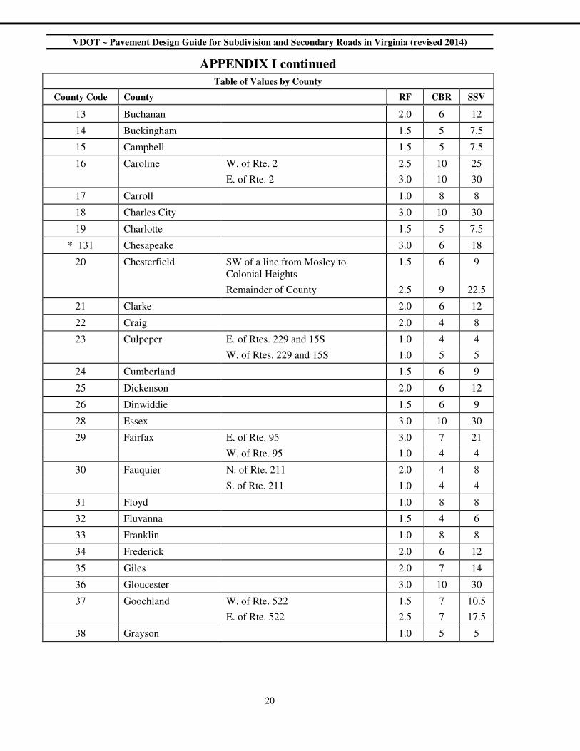
APPENDIX I continued
Table of Values by County
County Code County RF CBR SSV
13 Buchanan 2.0 6 12
14 Buckingham 1.5 5 7.5
15 Campbell 1.5 5 7.5
16 Caroline W. of Rte. 2 2.5 10 25
E. of Rte. 2 3.0 10 30
17 Carroll 1.0 8 8
18 Charles City 3.0 10 30
19 Charlotte 1.5 5 7.5
* 131 Chesapeake 3.0 6 18
20 Chesterfield SW of a line from Mosley to
Colonial Heights
1.5 6 9
Remainder of County 2.5 9 22.5
21 Clarke 2.0 6 12
22 Craig 2.0 4 8
23 Culpeper E. of Rtes. 229 and 15S 1.0 4 4
W. of Rtes. 229 and 15S 1.0 5 5
24 Cumberland 1.5 6 9
25 Dickenson 2.0 6 12
26 Dinwiddie 1.5 6 9
28 Essex 3.0 10 30
29 Fairfax E. of Rte. 95 3.0 7 21
W. of Rte. 95 1.0 4 4
30 Fauquier N. of Rte. 211 2.0 4 8
S. of Rte. 211 1.0 4 4
31 Floyd 1.0 8 8
32 Fluvanna 1.5 4 6
33 Franklin 1.0 8 8
34 Frederick 2.0 6 12
35 Giles 2.0 7 14
36 Gloucester 3.0 10 30
37 Goochland W. of Rte. 522 1.5 7 10.5
E. of Rte. 522 2.5 7 17.5
38 Grayson 1.0 5 5

VDOT ~ Pavement Design Guide for Subdivision and Secondary Roads in Virginia (revised 2014)
21
APPENDIX I continued
Table of Values by County
County Code County RF CBR SSV
39 Greene 1.0 5 5
40 Greensville E. of Rte. 95 3.0 9 27
W. of Rte. 95 1.5 9 13.5
41 Halifax 1.5 8 12
* 114 Hampton 3.0 9 27
42 Hanover E. of Rte. 95 3.0 10 30
W. of Rte. 95 and E. of Rte. 715 2.5 6 15
W. of Rte. 715 1.5 6 9
43 Henrico W. of Rte. 95 2.5 7 17.5
E. of Rte. 95 3.0 7 21
44 Henry 1.0 8 8
45 Highland 2.0 6 12
46 Isle of Wight 3.0 9 27
47 James City 3.0 6 18
48 King George 3.0 10 30
49 King and Queen 3.0 10 30
50 King William 3.0 10 30
51 Lancaster 3.0 10 30
52 Lee 2.0 6 12
53 Loudoun W. of Rte. 15 2.0 4 8
E. of Rte. 15 1.0 4 4
54 Louisa 1.5 5 7.5
55 Lunenburg 1.5 5 7.5
56 Madison 1.0 5 5
57 Mathews 3.0 10 30
58 Mecklenburg 1.5 7 10.5
59 Middlesex 3.0 10 30
60 Montgomery 2.0 5 10
61 Suffolk 3.0 9 27
62 Nelson 1.5 5 7.5
63 New Kent 3.0 9 27
* 121 Newport News 3.0 9 27
* 122 Norfolk 3.0 9 27
VDOT ~ Pavement Design Guide for Subdivision and Secondary Roads in Virginia (revised 2014)
22
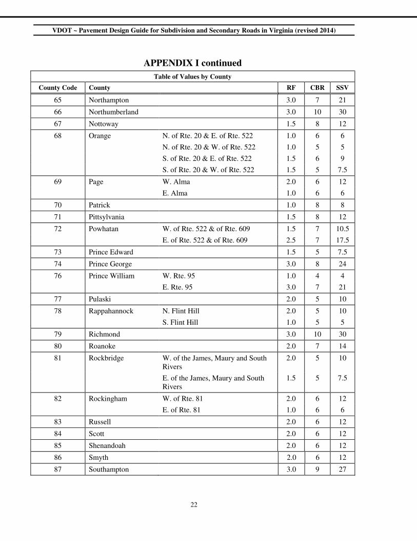
APPENDIX I continued
Table of Values by County
County Code County RF CBR SSV
65 Northampton 3.0 7 21
66 Northumberland 3.0 10 30
67 Nottoway 1.5 8 12
68 Orange N. of Rte. 20 & E. of Rte. 522 1.0 6 6
N. of Rte. 20 & W. of Rte. 522 1.0 5 5
S. of Rte. 20 & E. of Rte. 522 1.5 6 9
S. of Rte. 20 & W. of Rte. 522 1.5 5 7.5
69 Page W. Alma 2.0 6 12
E. Alma 1.0 6 6
70 Patrick 1.0 8 8
71 Pittsylvania 1.5 8 12
72 Powhatan W. of Rte. 522 & of Rte. 609 1.5 7 10.5
E. of Rte. 522 & of Rte. 609 2.5 7 17.5
73 Prince Edward 1.5 5 7.5
74 Prince George 3.0 8 24
76 Prince William W. Rte. 95 1.0 4 4
E. Rte. 95 3.0 7 21
77 Pulaski 2.0 5 10
78 Rappahannock N. Flint Hill 2.0 5 10
S. Flint Hill 1.0 5 5
79 Richmond 3.0 10 30
80 Roanoke 2.0 7 14
81 Rockbridge W. of the James, Maury and South
Rivers
2.0 5 10
E. of the James, Maury and South
Rivers
1.5 5 7.5
82 Rockingham W. of Rte. 81 2.0 6 12
E. of Rte. 81 1.0 6 6
83 Russell 2.0 6 12
84 Scott 2.0 6 12
85 Shenandoah 2.0 6 12
86 Smyth 2.0 6 12
87 Southampton 3.0 9 27

VDOT ~ Pavement Design Guide for Subdivision and Secondary Roads in Virginia (revised 2014)
23
APPENDIX I continued
Table of Values by County
County Code County RF CBR SSV
88 Spotsylvania W. of Rte. 95 1.5 6 9
E. of Rte. 95 2.5 10 25
89 Stafford W. of Rte. 95 1.0 6 6
E. of Rte. 95 3.0 10 30
90 Surry 3.0 9 27
91 Sussex W. of Rte. 95 1.5 9 13.5
E. of Rte. 95 3.0 9 27
92 Tazewell 2.0 6 12
* 134 Virginia Beach N. of Rte. 44 3.0 9 27
S. of Rte. 44 3.0 6 18
93 Warren 2.0 6 12
95 Washington 2.0 6 12
96 Westmoreland 3.0 10 30
97 Wise 2.0 6 12
98 Wythe 2.0 6 12
99 York 3.0 7 21
* Note: Arlington County, Henrico County, and independent cities identified with a “County Code”
greater than 99 have administrative jurisdiction over their own transportation facilities.
Consequently, for the development of new subdivision streets, the provisions of this guide
may not apply in those jurisdictions and developers are encouraged to seek the guidance of
appropriate authorities in those areas. However, these provisions shall apply in those
jurisdictions for all the Department managed projects.

VDOT ~ Pavement Design Guide for Subdivision and Secondary Roads in Virginia (revised 2014)
24
{Page Intentionally Blank}
VDOT ~ Pavement Design Guide for Subdivision and Secondary Roads in Virginia (revised 2014)
25
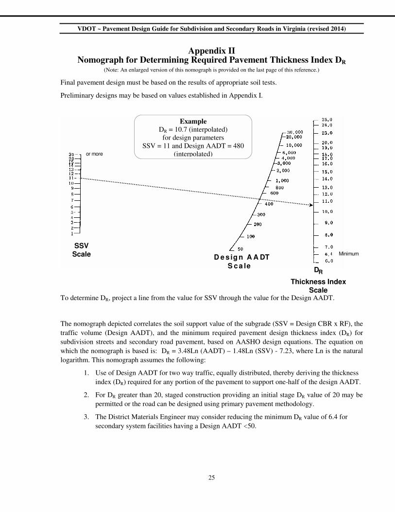
Appendix II Nomograph for Determining Required Pavement Thickness Index DR
(Note: An enlarged version of this nomograph is provided on the last page of this reference.)
Final pavement design must be based on the results of appropriate soil tests.
Preliminary designs may be based on values established in Appendix I.
To determine DR, project a line from the value for SSV through the value for the Design AADT.
The nomograph depicted correlates the soil support value of the subgrade (SSV = Design CBR x RF), the
traffic volume (Design AADT), and the minimum required pavement design thickness index (DR) for
subdivision streets and secondary road pavement, based on AASHO design equations. The equation on
which the nomograph is based is: DR = 3.48Ln (AADT) – 1.48Ln (SSV) - 7.23, where Ln is the natural
logarithm. This nomograph assumes the following:
1. Use of Design AADT for two way traffic, equally distributed, thereby deriving the thickness
index (DR) required for any portion of the pavement to support one-half of the design AADT.
2. For DR greater than 20, staged construction providing an initial stage DR value of 20 may be
permitted or the road can be designed using primary pavement methodology.
3. The District Materials Engineer may consider reducing the minimum DR value of 6.4 for
secondary system facilities having a Design AADT <50.
S S V S c a l e D e s i g n A A DT
S c a l e
T h i c k n e s s I n d e x S c a l e
D R
o r m o r e
M i n i m u m
Example
DR = 10.7 (interpolated)
for design parameters
SSV = 11 and Design AADT = 480
(interpolated)

VDOT ~ Pavement Design Guide for Subdivision and Secondary Roads in Virginia (revised 2014)
26
APPENDIX III
Paving Materials & Allowable Values Thickness
Equivalen
cy Value
Lift Thickness Max. No.
of Lifts in
a Design Location
& Notation Material
Material
Notation
Min.
inches
Max.
inches
Surface
a1
Asphalt Concrete (SM-9.0A or D)1
A.C. 1.67 *
1 1.5
13
Asphalt Concrete (SM-9.5A or D)
1 1 1.5
2
Asphalt Concrete (SM-12.5A or D)1
1.25 2
Prime & Double Seal or Class “C” or D”
Blotted Seal Coat Surface Treatments 4
D.S. 0.84 — — 1
Intermediate
a1 Asphalt Concrete (IM-19.0A or D)
1 A.C. 1.67 * 2 3 1
Asphalt Concrete (BM-25.0A or D) 1 A.C. 1.67 * 2.5 4 Multiple
6
Full Depth Asphalt Concrete (BM-25.0A
or D) over Subgrade1 A.C. 2.15
** 2.5 4 Multiple
6
Untreated Aggregate 5 Agg. 1.00 See Note
5
Cement Treated Aggregate6 CTA 1.67
Multiple6 Base
a2
Cement Treated Select Material, Type II6,
min. CBR = 20 Sel. Mat. C 1.50
Select Material Type I & II, non-plastic5,
min. CBR = 30 Sel. Mat. 0.84 6 10 See Note
5
Select Material, Type II, non-plastic5,
min. CBR = 20 Sel. Mat. 0.60
Soil Cement6 S.C. 1.00
Multiple6 Cement Treated Select Material, Type II
6 Sel. Mat. C 1.17
Cement Treated Select Borrow6 Sel. Bor. C 1.00
Open Graded Drainage Layer OGDL 0.60 2 3 1
Untreated Aggregate 5 Agg. 0.60 See Note
5
Cement Treated Aggregate6 CTA 1.33 Multiple
6
Select Material Type I, non-plastic5,
min. CBR = 30 Sel. Mat. 0.50 4 10
See Note5 Subbase
a3
Select Material Type II, non-plastic5,
min. CBR = 20 Sel. Mat. 0.40
Soil Cement6 S.C. 1.00
6 8
Multiple6 Soil Lime
6 S.L. 0.92
Cement Treated Select Material, Type II6 Sel. Mat. C 1.17
Cement Treated Select Borrow6 Sel. Bor. C 1.00

VDOT ~ Pavement Design Guide for Subdivision and Secondary Roads in Virginia (revised 2014)
27
Footnotes for Appendix III
1 When 4½ inches or more of any combination of Asphalt Concrete layers (surface + intermediate + base) is
called for on top of a subbase layer, the thickness equivalency value of 2.25 * shall be used for all the asphalt
concrete layers. When an asphalt base course is placed directly on subgrade, the resulting design is considered
a “Full-Depth Asphalt Concrete” pavement. The total depth of asphalt concrete layers (surface + intermediate
+ base) in such pavement shall be at least 6 inches and an equivalency value of 2.15
** shall be used for all the
asphalt concrete layers.
2 When to be placed directly upon an aggregate base course, a 2” minimum thickness is required and placement
in a single lift will be acceptable.
3 Two lifts of surface mix will be acceptable only under the case of phased construction where there will be at
least a year time lapse between placement of the initial lift and the final surface lift placement. The thicknesses
of the two lifts shall each conform to the minimum & maximum thicknesses in the table.
4 Prime and Double Seal Surface Treatment, in lieu of blotted seal coat surface treatment, may only be used as
outlined in Appendix IV (for new subdivision streets) and the current Location and Design Division I&I
Memorandum (for secondary road projects).
5 When plain aggregate materials are used in a design, the maximum combined thickness of base and subbase
layers shall be 12 inches for the purpose of calculating the thickness index value.
6 Multiple lifts of stabilized materials can be used in a design, as long as; they follow the General Notes and
Specifications on page 14 of this Guide.

VDOT ~ Pavement Design Guide for Subdivision and Secondary Roads in Virginia (revised 2014)
28
Appendix IV
Flexible Pavement Design Worksheet for New Subdivision Streets This sheet is intended for use and submission in conjunction with VDOT’s Secondary Street Acceptance Requirements
County Date:
Subdivision
Street Name
Design Engineer Phone:
AADT Projected traffic for the street segment considered, as defined in the Subdivision Street Requirements.
CBRD Design CBR = Average of CBRT x 2/3 and modified only as discussed in the Pavement Design Guide.
CBRT CBR value of the subgrade sample, taken and tested as specified in the Pavement Design Guide
DME VDOT District Materials Engineer
EPT Equivalent projected traffic
HCV Number of Heavy Commercial Vehicles (e.g. trucks, buses, etc., with 2 or more axles and 6 or more tires).
%HCV Percentage of the total traffic volume composed of Heavy Commercial Vehicles.
RF Resiliency Factor = Relative value of the subgrade soil’s ability to withstand repeated loading.
SSV Soil support value of subgrade (SSV = CBRD x RF)
DP Thickness index of proposed pavement design computed by the Conventional Pavement Design Method
DR Thickness index required, based on Design AADT and SSV, determined by Appendix II.
Step 1: Determine Design AADT Step 2: Determine Design Values
CBR, RF, and SSV
AADT Sample No. CBRT Resiliency Factor (RF)
%HCV = 100 ( HCV / AADT)
or
EPT = 20 x HCV
Note: For %HCV ≤ 5%, use AADT
_________
Note: For
%HCV>5%,
EPT>AADT
1 Source Value
2 Table 1
3 Appendix I
DME approved RF
For preliminary designs, use the lowest
RF value in the equation
Design AADT Use greater of AADT or EPT
CBRD x RF = SSV
(_______) x (_______) =
Step 3: Pavement Design (Check appropriate box and show proposed pavement design below.)
o (A) Limited to Design AADT ≤ 400 - Show pavement material notations and thickness from Appendix IV Tables A and B.
o (B) Show pavement section as developed in the Pavement Design Guide. (See Appendix III for material notations and thickness equivalency values (a)).
DR = ________
from Appendix II
Description of Proposed Pavement Section
Material Notation Thickness, h a (a x h)
Surface
Base
Subbase
DP must equal or exceed the value of DR. DP = Σ(a x h) =
VDOT ~ Pavement Design Guide for Subdivision and Secondary Roads in Virginia (revised 2014)
29
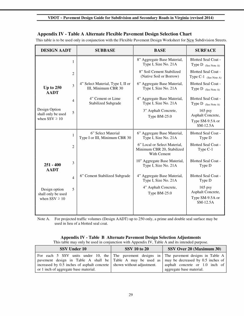
Appendix IV - Table A Alternate Flexible Pavement Design Selection Chart This table is to be used only in conjunction with the Flexible Pavement Design Worksheet for New Subdivision Streets.
DESIGN AADT SUBBASE BASE SURFACE
1
8” Aggregate Base Material,
Type I, Size No. 21A
Blotted Seal Coat -
Type D (See Note A)
2
8” Soil Cement Stabilized
(Native Soil or Borrow)
Blotted Seal Coat -
Type C-1 (See Note A)
Up to 250
AADT
3 4” Select Material, Type I, II or
III, Minimum CBR 30
6” Aggregate Base Material,
Type I, Size No. 21A
Blotted Seal Coat -
Type D (See Note A)
4
4” Cement or Lime
Stabilized Subgrade
4” Aggregate Base Material,
Type I, Size No. 21A
Blotted Seal Coat -
Type D (See Note A)
Design Option
shall only be used
when SSV ≥ 10
5 3” Asphalt Concrete,
Type BM-25.0
165 psy
Asphalt Concrete,
Type SM-9.5A or
SM-12.5A
1
6” Select Material
Type I or III, Minimum CBR 30
6” Aggregate Base Material,
Type I, Size No. 21A
Blotted Seal Coat -
Type D
2
6” Local or Select Material,
Minimum CBR 20, Stabilized
With Cement
Blotted Seal Coat -
Type C-1
251 - 400
AADT
3 10” Aggregate Base Material,
Type I, Size No. 21A
Blotted Seal Coat -
Type D
4
6” Cement Stabilized Subgrade 4” Aggregate Base Material,
Type I, Size No. 21A
Blotted Seal Coat -
Type D
Design option
shall only be used
when SSV ≥ 10
5 4” Asphalt Concrete,
Type BM-25.0
165 psy
Asphalt Concrete,
Type SM-9.5A or
SM-12.5A
Note A. For projected traffic volumes (Design AADT) up to 250 only, a prime and double seal surface may be
used in lieu of a blotted seal coat.
Appendix IV - Table B Alternate Pavement Design Selection Adjustments This table may only be used in conjunction with Appendix IV, Table A and its intended purpose.
SSV Under 10 SSV 10 to 20 SSV Over 20 (Maximum 30)
For each 5 SSV units under 10, the
pavement design in Table A shall be
increased by 0.5 inches of asphalt concrete
or 1 inch of aggregate base material.
The pavement designs in
Table A may be used as
shown without adjustment.
The pavement designs in Table A
may be decreased by 0.5 inches of
asphalt concrete or 1.0 inch of
aggregate base material.
VDOT ~ Pavement Design Guide for Subdivision and Secondary Roads in Virginia (revised 2014)
30
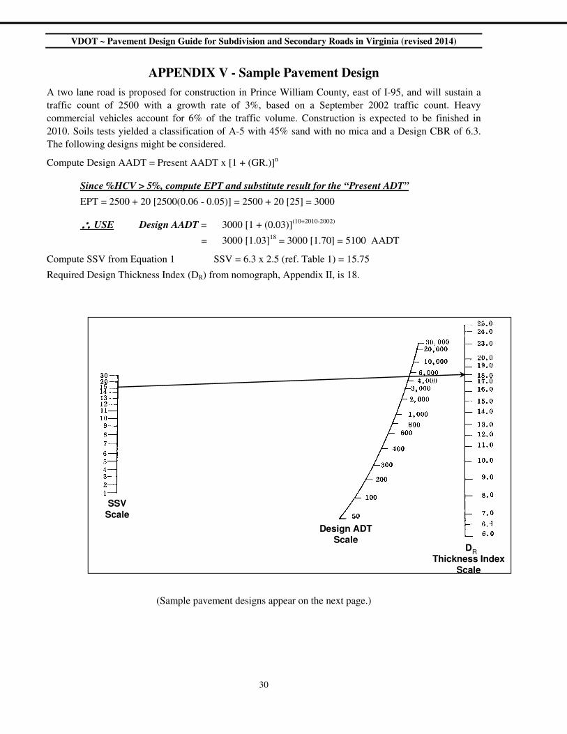
APPENDIX V - Sample Pavement Design
A two lane road is proposed for construction in Prince William County, east of I-95, and will sustain a
traffic count of 2500 with a growth rate of 3%, based on a September 2002 traffic count. Heavy
commercial vehicles account for 6% of the traffic volume. Construction is expected to be finished in
2010. Soils tests yielded a classification of A-5 with 45% sand with no mica and a Design CBR of 6.3.
The following designs might be considered.
Compute Design AADT = Present AADT x [1 + (GR.)]n
Since %HCV > 5%, compute EPT and substitute result for the “Present ADT”
EPT = 2500 + 20 [2500(0.06 - 0.05)] = 2500 + 20 [25] = 3000
∴∴∴∴ USE Design AADT = 3000 [1 + (0.03)](10+2010-2002)
= 3000 [1.03]18
= 3000 [1.70] = 5100 AADT
Compute SSV from Equation 1 SSV = 6.3 x 2.5 (ref. Table 1) = 15.75
Required Design Thickness Index (DR) from nomograph, Appendix II, is 18.
(Sample pavement designs appear on the next page.)
SSVScale
Design ADTScale
RD
Thickness IndexScale
VDOT ~ Pavement Design Guide for Subdivision and Secondary Roads in Virginia (revised 2014)
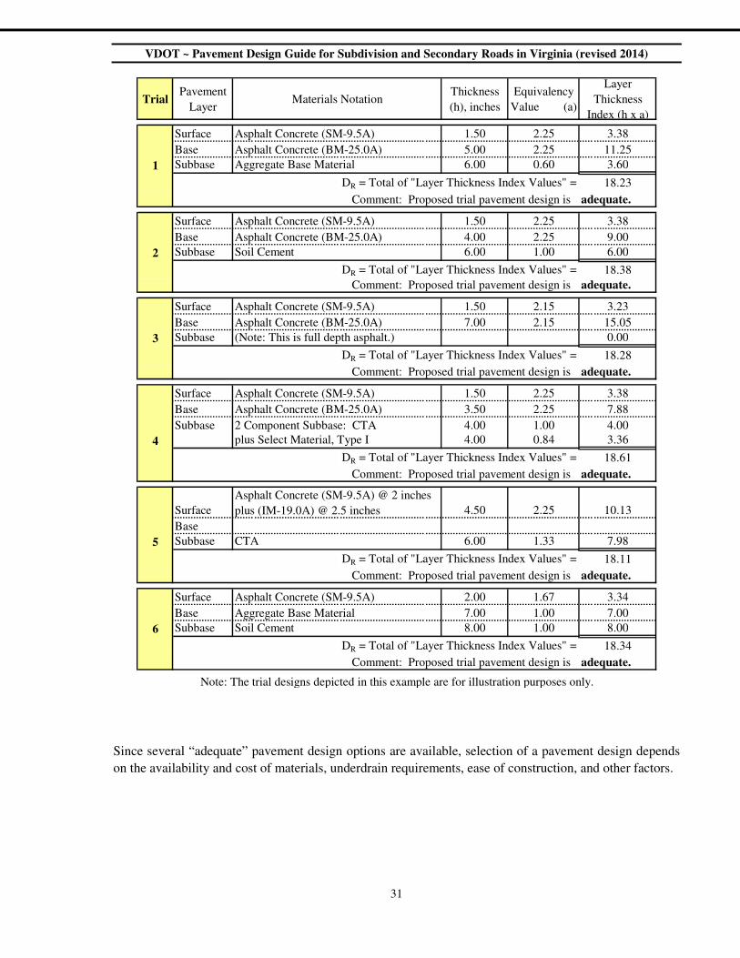
31
Since several “adequate” pavement design options are available, selection of a pavement design depends
on the availability and cost of materials, underdrain requirements, ease of construction, and other factors.
TrialPavement
LayerMaterials Notation
Thickness
(h), inches
Equivalency
Value (a)
Layer
Thickness
Index (h x a)
Surface Asphalt Concrete (SM-9.5A) 1.50 2.25 3.38
Base Asphalt Concrete (BM-25.0A) 5.00 2.25 11.25
1 Subbase Aggregate Base Material 6.00 0.60 3.60
DR = Total of "Layer Thickness Index Values" = 18.23
Comment: Proposed trial pavement design is adequate.
Surface Asphalt Concrete (SM-9.5A) 1.50 2.25 3.38
Base Asphalt Concrete (BM-25.0A) 4.00 2.25 9.00
2 Subbase Soil Cement 6.00 1.00 6.00
DR = Total of "Layer Thickness Index Values" = 18.38
Comment: Proposed trial pavement design is adequate.
Surface Asphalt Concrete (SM-9.5A) 1.50 2.15 3.23
Base Asphalt Concrete (BM-25.0A) 7.00 2.15 15.05
3 Subbase (Note: This is full depth asphalt.) 0.00
DR = Total of "Layer Thickness Index Values" = 18.28
Comment: Proposed trial pavement design is adequate.
Surface Asphalt Concrete (SM-9.5A) 1.50 2.25 3.38
Base Asphalt Concrete (BM-25.0A) 3.50 2.25 7.88
Subbase 2 Component Subbase: CTA 4.00 1.00 4.00
4 plus Select Material, Type I 4.00 0.84 3.36
DR = Total of "Layer Thickness Index Values" = 18.61
Comment: Proposed trial pavement design is adequate.
Surface
Asphalt Concrete (SM-9.5A) @ 2 inches
plus (IM-19.0A) @ 2.5 inches 4.50 2.25 10.13
Base
5 Subbase CTA 6.00 1.33 7.98
DR = Total of "Layer Thickness Index Values" = 18.11
Comment: Proposed trial pavement design is adequate.
Surface Asphalt Concrete (SM-9.5A) 2.00 1.67 3.34
Base Aggregate Base Material 7.00 1.00 7.00
6 Subbase Soil Cement 8.00 1.00 8.00
DR = Total of "Layer Thickness Index Values" = 18.34
Comment: Proposed trial pavement design is adequate.
Note: The trial designs depicted in this example are for illustration purposes only.
VDOT ~ Pavement Design Guide for Subdivision and Secondary Roads in Virginia (revised 2014)
32
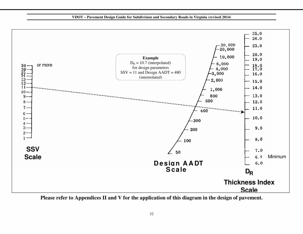
Please refer to Appendices II and V for the application of this diagram in the design of pavement.
S S V S c a l e
D e s i g n A A DT S c a l e
T h i c k n e s s I n d e x S c a l e
D R
o r m o r e
M i n i m u m
Example
DR = 10.7 (interpolated)
for design parameters
SSV = 11 and Design AADT = 480
(interpolated)
VDOT ~ Pavement Design Guide for Subdivision and Secondary Roads in Virginia (revised 2014)
33
APPENDIX VI: PCC Pavement Joint Detailing Example