pavement design concept
TRANSCRIPT
LECTURE 2- PAVEMENT DESIGN CONCEPT
Synopsis:
a. Pavement Structureb. Factors affecting pavementc. Design methods
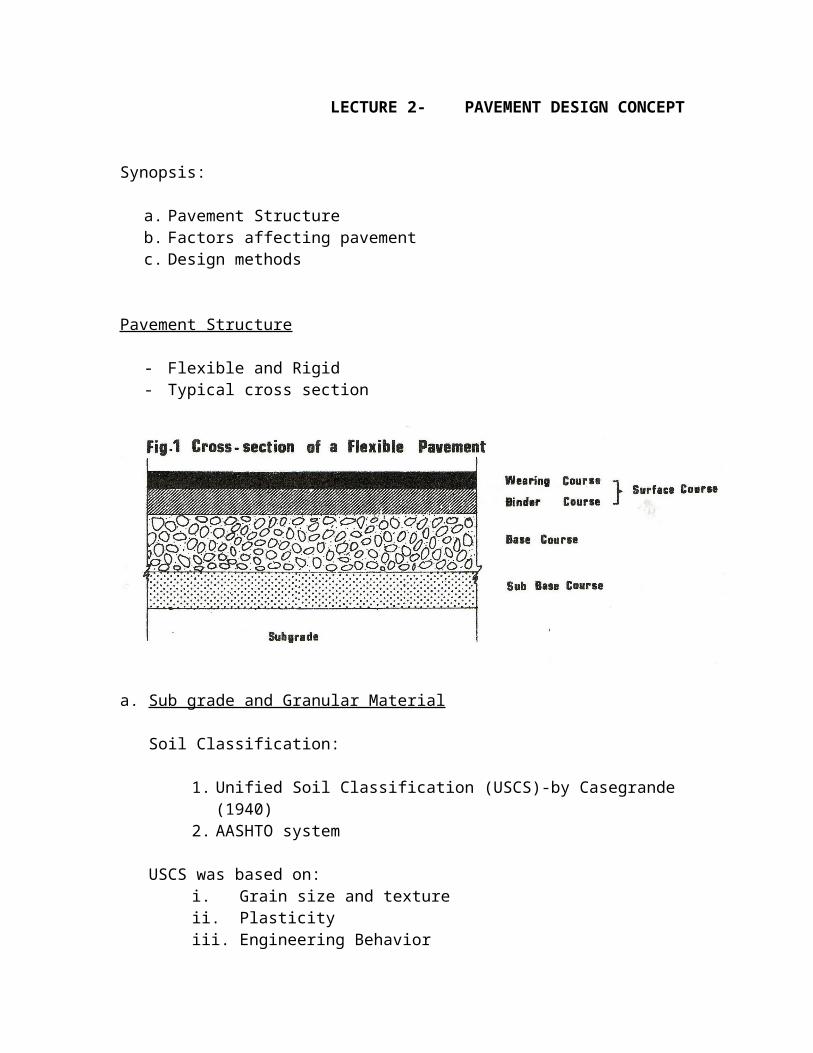
Pavement Structure
- Flexible and Rigid- Typical cross section
a. Sub grade and Granular Material
Soil Classification:
1. Unified Soil Classification (USCS)-by Casegrande (1940)2. AASHTO system
USCS was based on:i. Grain size and textureii. Plasticityiii. Engineering Behavior
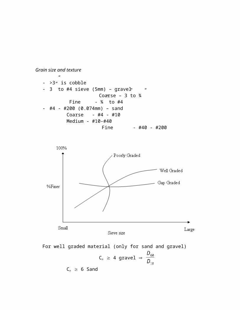
Grain size and texture
- >3” is cobble- 3” to #4 sieve (5mm) – gravel Coarse – 3”to ¾”
Fine - ¾” to #4- #4 - #200 (0.074mm) – sand
Coarse - #4 - #10Medium - #10-#40
Fine - #40 - #200
For well graded material (only for sand and gravel)
C 4 gravel
C 6 Sand
Cc [1 Cc 3]
To be well graded must satisfy both (Cc & Cu)
Where: C = coefficient of uniformity Cc = coefficient of curvature
Plasticity
- L.L – P.L = P.I- > 50% L.L =H- < 50% L.L = L
CL = lean or light or silty clay CH = Fat or buckshot or gumbo or heavy clay mL = Clay silts and sandy silts mH = Bulls liver
Engineering Behavior
- Permeability- Shear strength- Soil classification- Atterberg limits- Soil compressibility and settlement
b. Sub grade Strength Test
1. California Bearing Ratio (CBR)2. Triaxial test (Shear)3. Texas triaxial test4. Modulus of subgrade reaction (Plate loading)5. Resilient modulus6. Vane Shear test7. R-value test8. Dutch cone & Penetrometer tests9. Dynamic Cone Penetration (DCP)
Macadam roads
- John Macadam – 1800- Crushed stone for road- Water was used to bind stones- Two types:
i. Water bound Macadamii. Bituminous Macadam
Aggregate
- used crushed stones, lime stones and sand stones (hand)- must be free from dust, flat or elongated pieces- Hardness – L.A abrasion 40 max for wearing coarse (WC) and 50 max for base.
Aggregate Gradation
- Percent passing by weight2 ½” (63mm) ………..1002” (50mm)……………..90-1001 ½” (37mm)…………..35-701” (25.0mm)…………...0 – 15½”(12.5mm)…………...0 – 5
- Binder type : RT -10,11,12- Heating: 1210C- Application: 790C-1200C
Construction Method
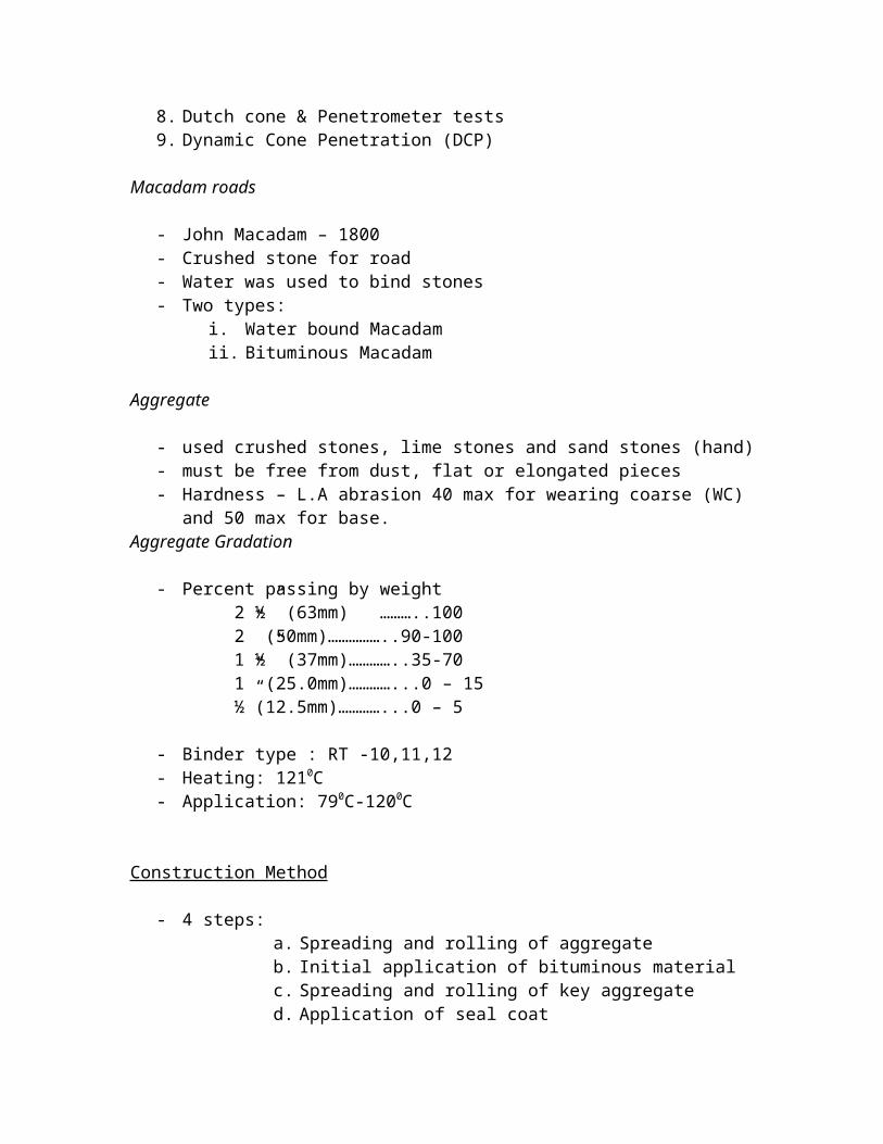
- 4 steps:a. Spreading and rolling of aggregateb. Initial application of bituminous materialc. Spreading and rolling of key aggregated. Application of seal coat
- Before rolling inspect/remove excessive fines, very large aggregate and flat and elongated aggregate.
- Rolling
Application of Bitumen
- use pressure distributor (1.75-2.25 gal/sq.yd)- Equipment required
i. Truckii. Insulated tankiii. Burner and Nozzle
- Spreading and rolling of key aggregate - Application of seal coat:
i. sweep to surface – broom drag to remove all loose materialii. bitumen applied
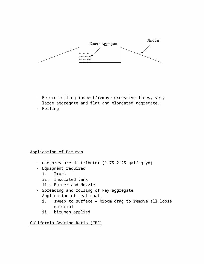
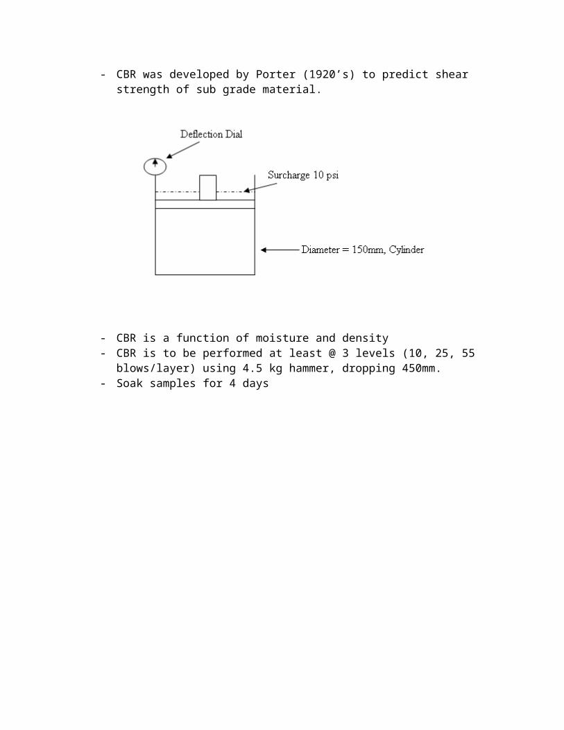
California Bearing Ratio (CBR)
- CBR was developed by Porter (1920’s) to predict shear strength of sub grade material.
- CBR is a function of moisture and density- CBR is to be performed at least @ 3 levels (10, 25, 55 blows/layer) using 4.5 kg
hammer, dropping 450mm.- Soak samples for 4 days
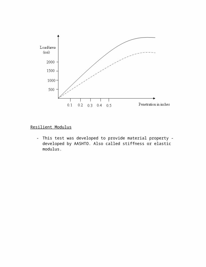
Resilient Modulus
- This test was developed to provide material property - developed by AASHTO. Also called stiffness or elastic modulus.
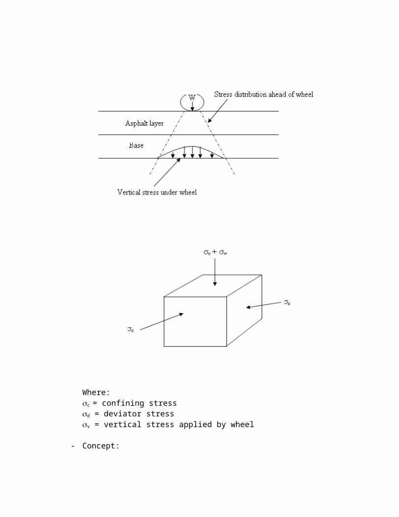
Where:c = confining stressd = deviator stressv = vertical stress applied by wheel
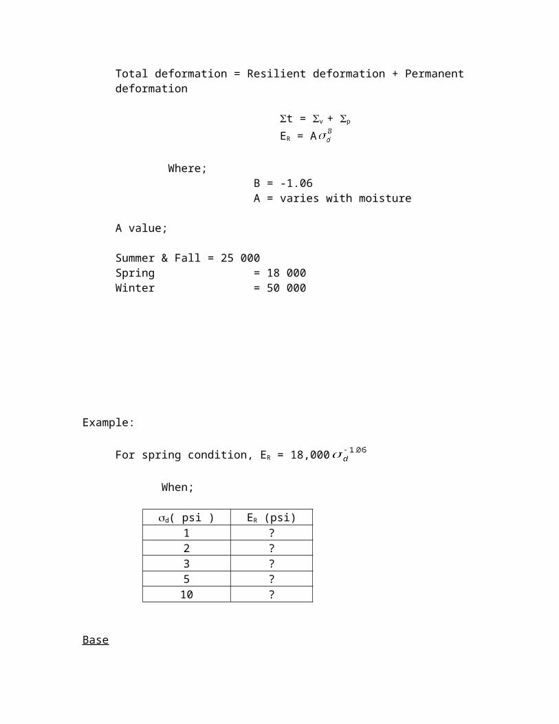
- Concept:Total deformation = Resilient deformation + Permanent deformation
t = v + p
ER = A
Where; B = -1.06 A = varies with moisture
A value;
Summer & Fall = 25 000Spring = 18 000Winter = 50 000
Example:
For spring condition, ER = 18,000
When;
d( psi ) ER (psi)1 ?2 ?3 ?5 ?10 ?
Base
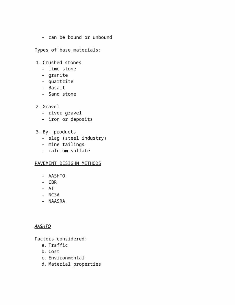
- can be bound or unbound
Types of base materials: 1. Crushed stones
- lime stone- granite- quartzite- Basalt- Sand stone
2. Gravel- river gravel- iron or deposits
3. By- products- slag (steel industry)- mine tailings- calcium sulfate
PAVEMENT DESIGHN METHODS
- AASHTO- CBR- AI- NCSA- NAASRA
AASHTO
Factors considered:a. Trafficb. Costc. Environmentald. Material properties
a. Traffici. vehicle type (load/tire, tire pressure and tire spacing)ii. Traffic volumeiii. Speed
b. Types of vehiclesi. Passenger carsii. Busesiii. RV’siv. Semi
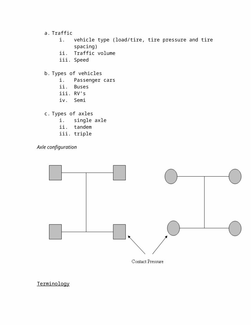
c. Types of axlesi. single axleii. tandemiii. triple
Axle configuration
Terminology
- Design period- Analysis period- ESAL
ESAL = fd x Git x AADT x 365 x Ni x FEi
Where:fd = design lane factorGit = growth factorNi = Number of axles in each categoryFEi = Load equivalency factor for each categoryFinal ESAL = ESAL x DD x LD
- SAL
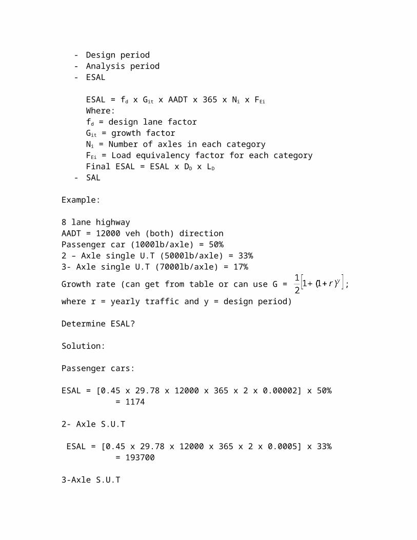
Example:
8 lane highwayAADT = 12000 veh (both) directionPassenger car (1000lb/axle) = 50%2 – Axle single U.T (5000lb/axle) = 33%3- Axle single U.T (7000lb/axle) = 17%
Growth rate (can get from table or can use G = ; where r = yearly traffic and
y = design period)
Determine ESAL?
Solution:
Passenger cars:
ESAL = [0.45 x 29.78 x 12000 x 365 x 2 x 0.00002] x 50% = 1174
2- Axle S.U.T
ESAL = [0.45 x 29.78 x 12000 x 365 x 2 x 0.0005] x 33% = 193700
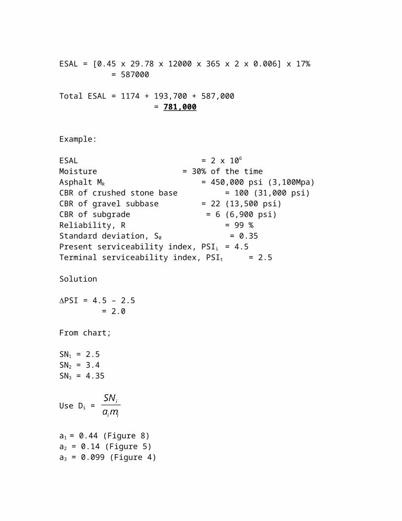
3-Axle S.U.T
ESAL = [0.45 x 29.78 x 12000 x 365 x 2 x 0.006] x 17% = 587000
Total ESAL = 1174 + 193,700 + 587,000
= 781,000
Example:
ESAL = 2 x 10⁶
Moisture = 30% of the timeAsphalt MR = 450,000 psi (3,100Mpa)CBR of crushed stone base = 100 (31,000 psi)CBR of gravel subbase = 22 (13,500 psi)CBR of subgrade = 6 (6,900 psi)Reliability, R = 99 %Standard deviation, S0 = 0.35Present serviceability index, PSIi = 4.5Terminal serviceability index, PSIt = 2.5
Solution
PSI = 4.5 – 2.5 = 2.0
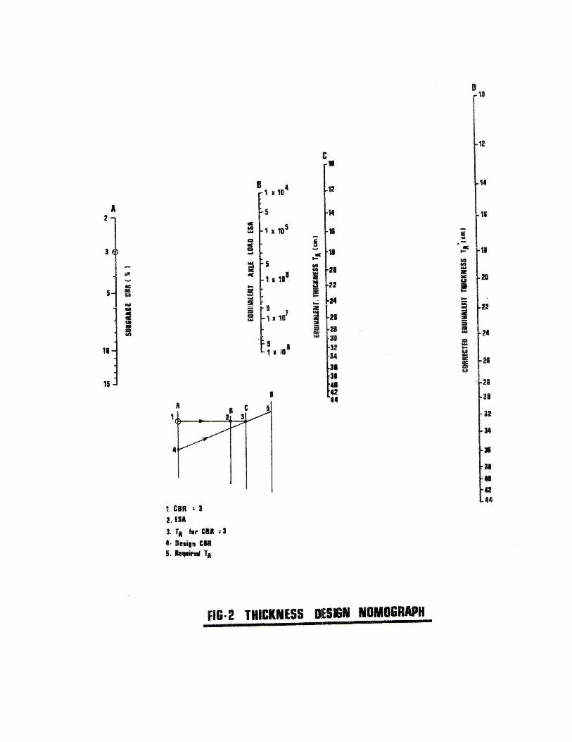
From chart;
SN1 = 2.5SN2 = 3.4SN3 = 4.35
Use Di =
a1 = 0.44 (Figure 8)a2 = 0.14 (Figure 5)a3 = 0.099 (Figure 4)
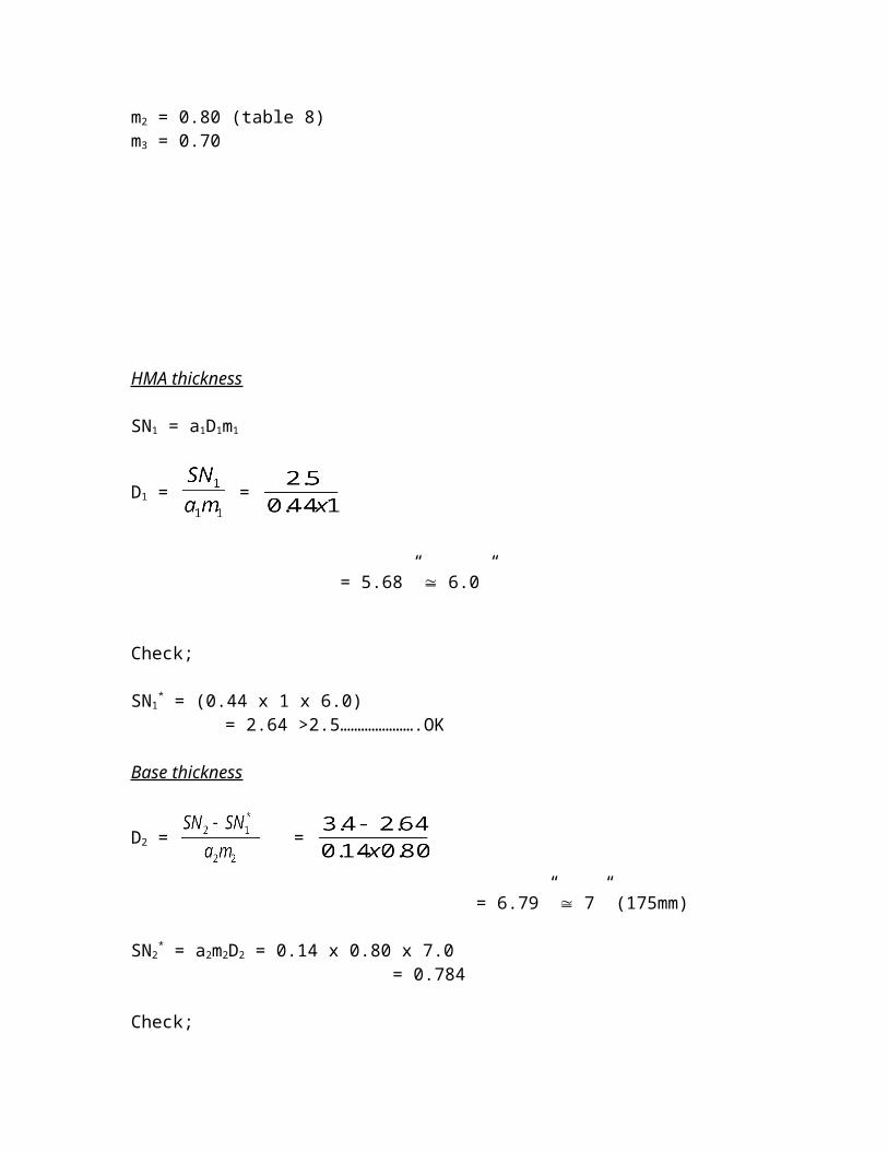
m2 = 0.80 (table 8)m3 = 0.70
HMA thickness
SN1 = a1D1m1
D1 = =
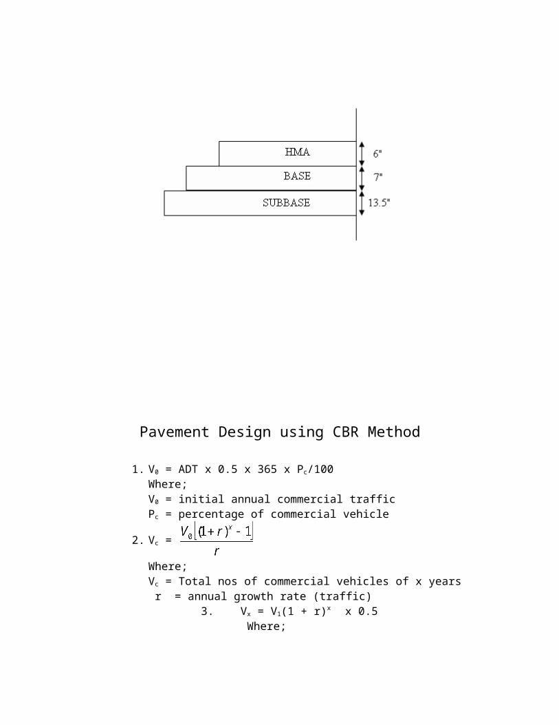
= 5.68” 6.0”
Check;
SN1* = (0.44 x 1 x 6.0)
= 2.64 >2.5………………….OK
Base thickness
D2 = =
= 6.79” 7” (175mm)
SN2* = a2m2D2 = 0.14 x 0.80 x 7.0
= 0.784
Check;
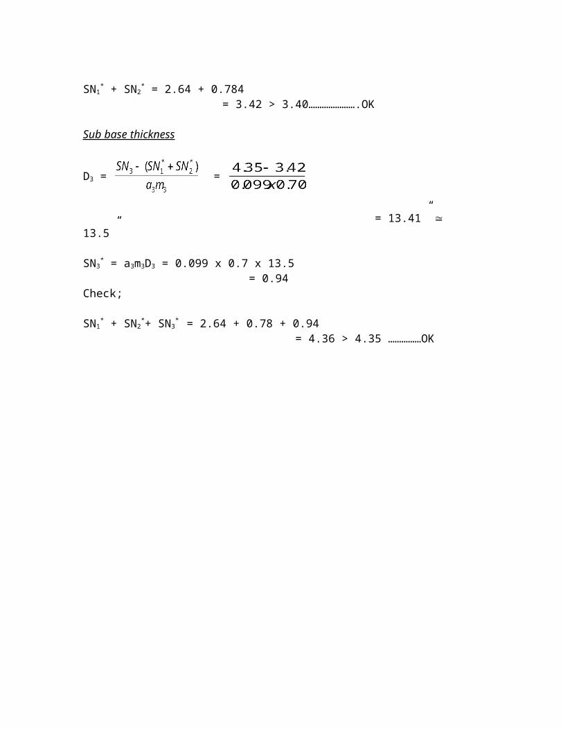
SN1* + SN2
* = 2.64 + 0.784 = 3.42 > 3.40………………….OK
Sub base thickness
D3 = =
= 13.41” 13.5”
SN3* = a3m3D3 = 0.099 x 0.7 x 13.5
= 0.94Check;
SN1* + SN2
*+ SN3* = 2.64 + 0.78 + 0.94
= 4.36 > 4.35 ……………OK
Pavement Design using CBR Method
1. V0 = ADT x 0.5 x 365 x Pc/100Where;V0 = initial annual commercial trafficPc = percentage of commercial vehicle
2. Vc =
Where;Vc = Total nos of commercial vehicles of x years r = annual growth rate (traffic)
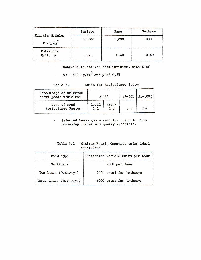
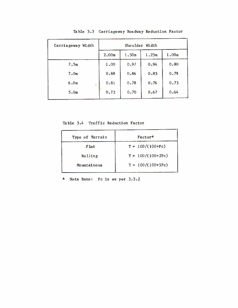
3. Vx = V1(1 + r)x x 0.5 Where; Vx = vol. of daily traffic after x years (one direction) V1 = initial daily traffic (one direction) x = design period 4. C = I x R x T Where; C = max. one way hourly capacity I = ideal hourly capacity (table 3.2) R= roadway factor (table 3.3) T = traffic reduction factor (table 3.4)
- If traffic estimate for the design period exceeds the daily capacity, C; then calculate no. of n required to reach daily capacity.
- Where;
n = ; n = period required to reach capacity and c = 24 hours one
way capacity (10 x C)- For varying CBR values within top 1m of soil:
CBR =
Where; h = thickness of soil strata
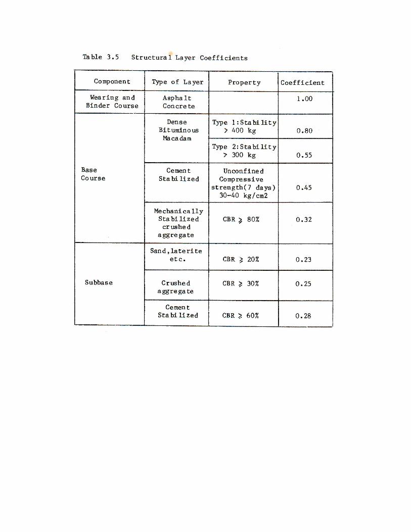
h1 + h2 + h3 +……..+ hn = 100cm 5. Layer thickness TA = a1D1 + a2D2 +………+ anDn
Where;TA = equivalent thicknessan = layer coefficient
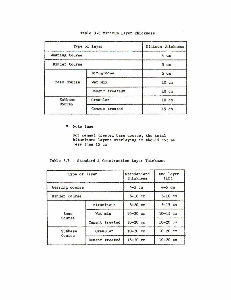
Dn = depth Selection of D from tables