parts manual - middleby | the middleby · pdf file · 2006-10-27parts manual for...
TRANSCRIPT

Parts Manualfor domestic and standard export ovens
PS520G-Series Gas Ovens:English
SPL092606-PF-BDSeptember 29, 2006
©2006 Middleby Marshall Inc.
Serial TagLocation
www.middleby.comemail: [email protected]
phone: 847-741-3300 • fax: 847-741-44061400 Toastmaster Drive • Elgin, IL 60160
Serial Number Code:First Four Digits - Order Of ProductionFifth Digit - Model SpecificSixth & Seventh Digit - Month of ProductionEight & Ninth Digit - Year of Production047270906 - Starting Serial Number and Higher
Table Of Contents: Page III

II
WARNINGFOR YOUR SAFETY, DO NOT STORE ORUSE GASOLINE OR OTHER FLAMMABLE
VAPORS AND LIQUIDS IN THE VICINITY OFTHIS OR ANY OTHER APPLIANCE.
WARNINGImproper installation, adjustment, alteration,service, or maintenance can cause propertydamage, injury, or death. Read the installa-tion, operating, and maintenance instruc-
tions thoroughly before installing or servic-ing this equipment.
NOTICEThe warranty is NOT VALID unless the oven is installed, started, and demon-
strated under the supervision of a factory-authorized installer
NOTICEContact your authorized Service Agency to perform maintenance and
repairs. A Service Agency Directory is supplied with your oven.
NOTICEUsing any parts other than genuine Middleby Marshall factory-manufactured
parts relieves the manufacturer of all warranty and liability.
NOTICEMiddleby Marshall (Manufacturer) reserves the right to change specifications
at any time.
KEEP THIS MANUAL IN A VISIBLE LOCATION NEAR THEOVEN FOR FUTURE REFERENCE.

III
TABLE OF CONTENTS
Oven Specifications ........................................................................... 1
Oven Dimensions............................................................................ 2-3
Installation Kit .................................................................................... 4
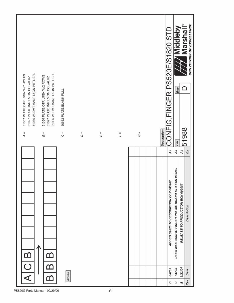
Key Parts List ..................................................................................... 5
Finger placement and part number .................................................... 6
Front view of oven ............................................................................. 7
Parts for front view of oven ................................................................ 8
View of right hand of electrical compartment ..................................... 9
Parts for right hand electrical compartment ..................................... 10
Rear-view blower compartment ....................................................... 11
Parts for rear-view blower compartment .......................................... 12
View of left hand electrical compartment ......................................... 13
Parts for left hand electrical compartment ....................................... 14
View of conveyor parts .................................................................... 15
Parts for conveyor ............................................................................ 16
WIRING DIAGRAMS
208/240V World Oven - 59113C...................................................... 17

1 PS520G Parts Manual - 09/29/06
PS520G SERIES OVEN SPECIFICATIONS
Conveyor Belt Width 18.00” (457mm)
Heating Zone Length 20.00” (5098mm)
Baking Area Square Feet 2.5 sq ft (.023 sq. m.)
Overall Dimensions
Standard Single Oven w/Legs 42.00” (1067mm) L x
35.21” (894mm) W x
21.10” (536mm) H x
Overall Dimensions
Double Oven 42.00” (1067mm) L x
35.21” (894mm) W x
36.64” (931mm) H x
Overall dimensions
Triple Oven 42.00” (1067mm) L x
35.21” (894mm) W x
48.19” (1224mm) H x
Weight of Single Oven 250 lbs (93.3kg)
Shipping Weight 325 lbs (121.3kg)
Shipping Cube 22.1 ft3 (0.62 m3)
Operating Range 8.3 kW/hr
Maximum Operating temperature 5500F (2870C)
Warm-up Time 20 min.
Belt Speed Limits 1-10 minutes
SERIES PS520 ELECTRICAL SPECIFICATIONSMain Blower & Control Circuit Phase Frequency Amperage Poles Wires
Elements Voltage Voltage Draw
All Models 208-240V 208-240V 1 Ph 50/60 Hz 1.5 Amp 2 Pole 3 Wire(2 hot, 1 grd)
GAS ORIFICE AND PRESSURE SPECIFICATIONS (PER OVEN CAVITY) - DOMESTIC AND STANDARD EXPORT OVENS
Gas Type BTU Main Orifice I.D. Bypass Orifice I.D. Supply (Inlet) Pressure Orifice (Manifold) Pressure
Natural 40,000 0.082” (2.08mm, #45 drill) 0.073” (2.0574mm, #49 drill) 6-12” W.C. (14.9-29.9mbar)* 3.5” W.C. (8.72mbar)
Propane 40,000 0.057” (1.45mm, #46 drill) 0.052” (1.85mm, #55 drill) 11-14” W.C. (27.4-34.9mbar) 7” W.C. (17.44mbar)
* The gas supply pressures and orifices sizes shown are for ovens installed in North America. The required gas supply pressures and orificesizes of ovens installed in other locations are dependant on the local gas type and on all applicable codes.
GAS ORIFICE AND PRESSURE SPECIFICATIONS (PER OVEN CAVITY) - DOMESTIC AND STANDARD EXPORT OVENS
Main UK, CH, IT, AT SE, CH, AT, DK BE, IE, IT, PT,Gas Orifice DK, FI NL DE BE,FR FI, DE, NL ES, UK (Manifold) HeatType dia. I2H I2L I2E I2E+ I3B/P I3+ Pressure Input
G20 2.3749mm 20mbar -- 20mbar 20mbar -- -- 11.21mbar 22.36kW-hr
G25 2.3749mm -- 25mbar -- -- -- -- 16.19mbar 22.36kW-hr
G30 1.3970mm -- -- -- -- 29 or 50mbar 28-30, 37 26.2mbar 22.59kW-hror 50mbar
2PS520G Parts Manual - 09/29/06
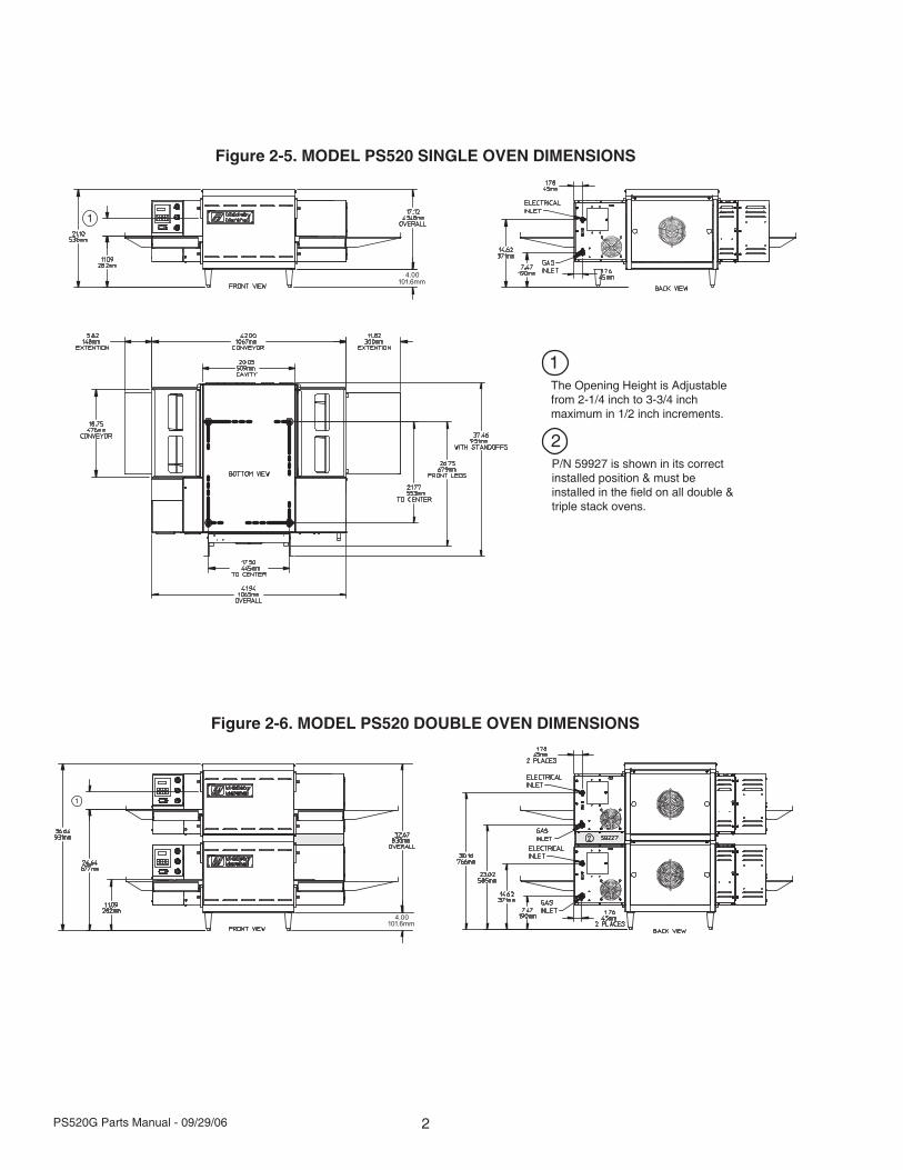
Figure 2-5. MODEL PS520 SINGLE OVEN DIMENSIONS
Figure 2-6. MODEL PS520 DOUBLE OVEN DIMENSIONS
The Opening Height is Adjustablefrom 2-1/4 inch to 3-3/4 inchmaximum in 1/2 inch increments.
1
P/N 59927 is shown in its correctinstalled position & must beinstalled in the field on all double &triple stack ovens.
2

3 PS520G Parts Manual - 09/29/06
Figure 2-7. MODEL PS520 TRIPLE OVEN DIMENSIONS
The Opening Height is Adjustablefrom 2-1/4 inch to 3-3/4 inchmaximum in 1/2 inch increments.
1P/N 59927 is shown in its correctinstalled position & must beinstalled in the field on all double &triple stack ovens.
2

4PS520G Parts Manual - 09/29/06
PARTS LIST FOR SERIES PS520 GAS OVENINSTALLATION KIT
Single, Double and Triple Stack Ovens
Single Double TripleKit #--> 59182 59183 59184
ItemNO. QTY QTY QTY PART NO. DESCRIPTION
1 .................... 4 ...................... 4 .................... - ....................... 3101908 Leg 4”
2 .................... 1 ...................... 1 ................... 1 ......................... 48395 Bottom Tray w/insulation
3 .................... 1 ...................... 1 ................... 1 ......................... 48396 Top cover
4 .................... 4 ...................... 4 ................... 4 ......................... 51387 Screw MSSLT Thread 8-32 x 1/2, 18-8
5 .................... 1 ...................... 1 ................... 1 ......................... 59223 Installation & Operation Manual - English
6 .................... 1 ...................... 2 ................... 3 .................... 22361-0001 Flexible gas hose 48”
7 .................... 1 ...................... 1 ................... 1 .................... 22450-0228 Restraint Cable
8 .................... - ....................... 1 ................... 2 ......................... 59227 Guard - Heat (must be installed in field)
9 .................... - ....................... - .................... 4 ........................ M3828 Pin - Alignment
10 ................... 1 ...................... 2 ................... 3 ......................... 49975 Cord & plug (L6-20P)
10A .................. 1 ...................... 2 ................... 3 ......................... 49976 Cord only CE
11 ................... 1 ...................... 2 ................... 3 .................... 23115-0009 Manual on/off gas valve
12 ................... 1 ...................... 2 ................... 3 ......................... 31823 3/4” to 1/2” NPT reducer

5 PS520G Parts Manual - 09/29/06
PS520-SERIES GAS OVEN KEY PARTS
ITEM PART NO. DESCRIPTION QUANTITY1 28041-0011 Contactor, DP 25A 208/240V 1
2 58390 Motor, Conveyor Drive 1
3 31651 Signal Amplifier Board 1
4 33812-5 Thermocouple, Type “J” Shielded 2.50” x 120” 3
5 59450 Valve, Module M420 (41647) 1
6 48455 Ignitor, Single Rod 1
7 50239 Ignition, Spark Module 24VAC 50/60Hz 1
8 50610 Switch, Air .13” W.C. 1
9 47321 Control, Combo 4-20MA (58504) 1
10 58323 Controller, Digital w/o Dip Switch 1
11 59142 Valve, Gas PS520 - Nat Gas 1
12 36451 Fan, Cooling 230VAC 295 CFM 1
13 50240 Ignition Cable 25” 1
14 52244 Main Blower 2
15 33983 High Limit Module 1
1
2 3
4
5
6
7
89
10
11 12
13
14
15
6PS520G Parts Manual - 09/29/06

7 PS520G Parts Manual - 09/29/06
Fron
t Vie
w O
f Ove
nPS520G-SERIES PARTS MANUAL
Ser
ial T
ag L
ocat
ion
Mus
t be
inst
alle
d in
the
field
on
Dou
ble
and
Trip
le s
tack
ove
ns.
8PS520G Parts Manual - 09/29/06
Par
ts F
or F
ront
Vie
w O
f Ove
n
ITE
MQ
TYP
AR
T N
O.
DE
SC
RIP
TIO
N
11
4838
2U
pper
LH
End
Plu
g A
ssem
bly,
incl
udes
item
5 e
yebr
ow
21
4838
7Lo
wer
LH
End
Plu
g A
ssem
bly
31
4840
8Lo
wer
RH
End
Plu
g A
ssem
bly
41
4841
2U
pper
RH
End
Plu
g A
ssem
bly,
incl
udes
item
6 e
yebr
ow
51
4837
8E
yebr
ow, U
pper
LH
End
Plu
g A
ssem
bly
61
4841
0E
yebr
ow, U
pper
RH
End
Plu
g A
ssem
bly
74
5139
8E
nd P
lug
Mou
ntin
g B
rack
et A
ssem
bly
.875
”
88
2129
6-00
05S
crew
, Hex
Hea
d, W
SH
HD
12-
14x3
/4 S
S B
SD
96
3645
2N
ut, W
ing-
Pla
stic
1/4
-20
104
3101
908
Leg,
4” A
DJ
FT (N
PS
)
111
4839
5B
otto
m T
ray
Ass
embl
y
121
4839
6C
over
, Top
134
5138
7S
cr, M
S, S
LT T
HR
D 8
-32x
1/2”
18-
8
141
4997
5C
ords
et, L
6-20
P
14A
149
976
Cor
d on
ly (C
E M
odel
s)
151
4573
9N
amep
late
, Mid
dleb
y M
arsh
all
161
4786
1C
over
, Mot
or
174
M38
28A
lignm
ent P
in (T
riple
Sta
ck)
18
1 or
2
5922
7 G
uard
, Hea
t (m
ust b
e in
stal
led
in th
e fie
ld o
n D
oubl
e an
dTr
iple
sta
ck o
vens
PS520G-SERIES PARTS MANUAL

9 PS520G Parts Manual - 09/29/06
Vie
w o
f Lef
t Han
d E
lect
rica
l Com
part
men
tPS520G-SERIES PARTS MANUAL

10PS520G Parts Manual - 09/29/06
Par
ts F
or L
eft H
and
Ele
ctri
cal C
ompa
rtm
ent
ITE
MQ
TYP
AR
T N
O.
DE
SC
RIP
TIO
N
13
4652
1K
it B
low
er S
witc
h (C
onta
ins
(1) 4
4697
, (1)
446
96)
41
5832
3C
onve
yor
Spe
ed c
ontro
l w/D
igita
l Spe
ed D
ispl
ay
51
3750
3D
igita
l Spe
ed C
ontro
l (D
ispl
ay O
nly)
61
4732
1Te
mpe
ratu
re C
ontro
l (58
504)
71
2804
1-00
11C
onta
ctor
, 208
/240
V-2
5A
81
3150
4Tr
ansf
orm
er, 2
30V
(P)/1
20(S
), 20
0VA
91
2802
1-00
47S
witc
h, In
terlo
ck, 1
0A, N
O 2
Pol
e
101
3398
3C
ontro
l, E
lect
ric, H
i-Lim
it, 2
40V
111
5839
0M
otor
, Con
veyo
r Driv
e W
ith 2
-Pol
e M
agne
t
11a
139
002
Mag
net 2
-Pol
e
11b
131
0-00
17A
dhes
ive
11d
158
484
Kit,
2 b
rush
es &
2 c
aps
121
3818
5S
enso
r-C
onve
yor
Pic
k-up
131
3514
5S
witc
h, P
ush-
butto
n, M
olve
no, 2
50V
142
4503
6B
reak
er, C
ircui
t 240
V, 3
A
151
4863
5B
reak
er, C
ircui
t 240
V, 0
.3A
161
or 2
3381
2-5
Ther
moc
oupl
e, T
ype
“j”, S
hiel
ded,
2.5
”x 2
0”

11 PS520G Parts Manual - 09/29/06
Rea
r V
iew
Of B
low
er C
ompa
rtm
ent
As
view
ed fr
om th
e re
arbl
ower
mot
or s
pins
CC
W
PS520G-SERIES PARTS MANUAL
Gas
Inpu
t

12PS520G Parts Manual - 09/29/06
Par
ts F
or R
ear
Vie
w B
low
er C
ompa
rtm
ent
ITE
MQ
TYP
AR
T N
O.
DE
SC
RIP
TIO
N
11
2802
1-00
61S
witc
h, M
omen
tary
-10A
, NO
2 P
ole
22
3092
7B
umpe
r, W
indo
w
31
3645
1Fa
n, C
oolin
g, 2
30V
AC
, 295
CFM
42
5224
4M
otor
, Blo
wer
, CW
, 208
/230
V 5
0/60
Hz
With
Blo
wer
Whe
el
52
5725
8P
late
, Air
Ven
t
64
7007
413
SC
R, S
houl
der
10-3
2x3/
4 18
-8
71
3149
7G
uard
-Coo
ling
Fan
81
2747
0-00
04G
uard
- R
ight
Han
d C
ontro
l Com
partm
ent
PS520G-SERIES PARTS MANUAL

13 PS520G Parts Manual - 09/29/06
Vie
w O
f Rig
ht H
and
Of E
lect
rica
l Com
part
men
tPS520G-SERIES PARTS MANUAL

14PS520G Parts Manual - 09/29/06
ITE
MQ
TYP
AR
T N
O.
DE
SC
RIP
TIO
N
11
or 2
3381
2-5
Ther
moc
oupl
e, T
ype
“J”
Shi
elde
d 2.
5” x
120
”
21
2802
1-00
47S
witc
h, In
terlo
ck
32
3000
2Ta
p, P
lug
41
5902
3M
anifo
ld
5A2
5914
4M
ain
Orif
ice
Nat
ural
#45
.082
”
5B2
5914
3M
ain
Orif
ice
Pro
pane
0.0
57” (
1.45
mm
)
61
5912
5C
over
Pla
te, I
nsho
t Bur
ner H
ousi
ng
71
5900
6A
ssem
bly,
Bur
ner
Tube
s
8 1
4845
5 Ig
nito
r
92
5900
2B
urne
r, In
shot
101
5061
0A
ir S
witc
h
111
3381
3R
FI F
ilter
121
2747
0-00
04Fa
n G
uard
131
4187
2Tr
ansf
orm
er 2
40V
Pri,
24V
Sec
25V
A
141
3210
8Tr
ansf
orm
er 2
40V
Pri,
24V
Sec
65V
A
151
4564
4C
ircui
t Bre
aker
, 1 A
mp
161
5914
2C
ombo
Gas
Val
ve -
Nat
ural
Gas
Par
ts F
or R
ight
Han
d E
lect
rica
l Com
part
men
t
16A
159
416
Kit,
Con
vert
gas
valv
e to
NAT
16B
159
415
Kit,
Con
vert
gas
valv
e to
LP
171
3165
1A
mpl
ifier
Boa
rd18
150
239
Igni
tion
Mod
ule
191
5024
0Ig
nitio
n C
able
25"
(635
mm
)20
159
450
Mod
ulat
ing
Gas
Val
ve (4
1647
)21
150
794
Igni
tion
Rel
ay22
244
888
Fitti
ng, C
ompr
essi
on23
A1
5914
5O
rific
e B
ypas
s, N
atur
al #
49 .0
73”
23B
149
948
Orif
ice
Byp
ass,
Pro
pane
0.0
520"
#55
241
4439
0Te
rmin
al B
lock
25A
159
146
LP to
Nat
Kit
(incl
udes
16A
, 5A
, 23A
)25
B1
5914
7N
at to
LP
Kit
(incl
udes
16B
, 5B
, 23B
)26
159
018
Byp
ass
Tube
271
5912
7P
ipe
Ass
embl
y C
lam
p28
159
227
Hea
t Gua
rd29
137
000-
0781
Pip
e C
lam
p

15 PS520G Parts Manual - 09/29/06
Vie
w o
f Con
veyo
r P
arts
PS520G-SERIES PARTS MANUAL

16PS520G Parts Manual - 09/29/06
Par
ts F
or C
onve
yor
ITE
MQ
TYP
AR
T N
O.
DE
SC
RIP
TIO
N
11
5927
5W
eldm
ent
22
M48
17B
earin
g, R
ulon
31
M48
15S
haft,
Driv
e
41
5927
1S
haft,
Idle
r
510
M48
18S
proc
ket,
Wire
Bel
t
61
5930
7B
elt,
Wire
, Sta
inle
ss S
teel
, 18”
x87-
1/2”
71
5839
1K
it, M
aste
r Lin
k Fr
ont,
Mid
dle,
Rea
r
101
5556
7A
ssy,
Cha
in H
igh
Spe
ed w
/Mas
ter L
ink
10a
131
0-12
12M
aste
r Lin
k O
nly
111
5521
7S
proc
ket,
chai
n #2
5-20
T-1/
2” C
onve
yor
Sha
ft
121
4534
9S
proc
ket,
25B
25 w
/5/1
6” B
ore
- Driv
e S
haft
131
5839
0M
otor
, Con
veyo
r Driv
e w
/2 P
ole
Mag
net
13a
139
002
Mag
net 2
-Pol
e
13b
131
0-00
17A
dhes
ive
13c
158
484
Kit,
2 B
rush
es &
2 C
aps
141
3818
5S
enso
r-C
onve
yor
Pic
k-up
151
5928
0E
xten
sion
, Con
veyo
r - 6
”
161
5927
2E
xten
sion
, Con
veyo
r - 1
2”
172
5140
9P
an, C
rum
b V
ente
d -
Shi
pped
As
Sta
ndar
d
182
5927
6S
crew
Adj
ustm
ent
192
5926
4B
ushi
ng, R
ulon
- Id
ler
201
5926
7Id
ler
Gui
de -
Bac
k
211
5927
0Id
ler G
uide
- Fr
ont

17 PS520G Parts Manual - 09/29/06
Dra
win
g 59
113
Rev
C: W
iring
Dia
gram
, 208
/240
V -
GA
S, W
orld
Ove
n
PS520E-SERIESSCHEMATICS

18PS520G Parts Manual - 09/29/06

WARNINGImproper installation, adjustment, alteration, service or
maintenance can cause property damage, injury or death. Readthe installation, operating and maintenance instructionsthoroughly before installing or servicing this equipment.
NOTICEDuring the warranty period. ALL parts replacement and servicing should be
performed by your Middleby Marshall Authorized Service Agent. Service that isperformed by parties other than your Middleby Marshall Authorized Service Agent
may void your warranty.
NOTICEUsing any parts other than genuine Middleby Marshall factory manufactured parts
relieves the manufacturer of all warranty and liabilities.
NOTICEMiddleby Marshall reserves the right to change specifications at any time.
Middleby is proud to support the Commercial FoodEquipment Service Association (CFESA). We
recognize and applaud CFESA’s ongoing efforts toimprove the quality of technical service in the industry.
Middleby Cooking Systems Group • 1400 Toastmaster Drive • Elgin, IL 60120 • USA • (847) 741-3300 • FAX (847) 741-4406www.middleby.com