parts cleaners - ultimate washer operations manual.pdfparts cleaners – aqueous/solvent operations...
TRANSCRIPT
795-90716GM 12-02
®
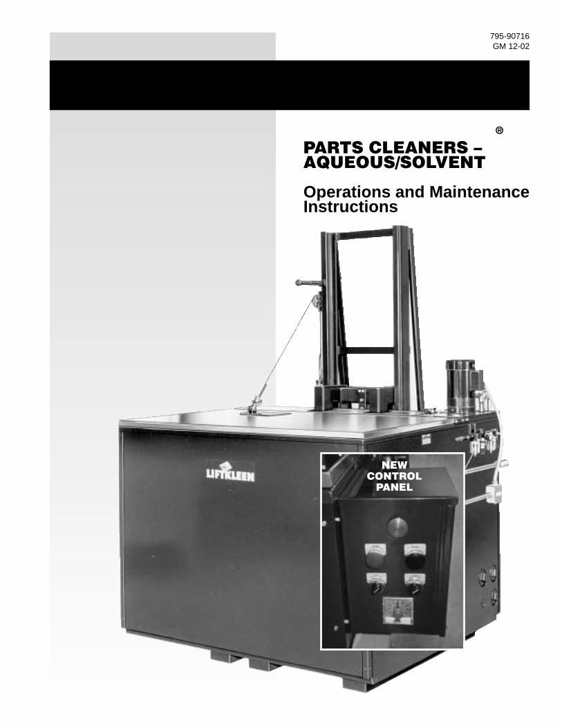
PARTS CLEANERS –AQUEOUS/SOLVENT
Operations and MaintenanceInstructions
NEWCONTROL
PANEL
WARNINGS/CAUTIONS . . . . . . . . . . . . . . . . . . .2INTRODUCTION . . . . . . . . . . . . . . . . . . . . . . . . .4LIFTKLEEN CONSTRUCTION FEATURES . . . .4
TANK ASSEMBLY . . . . . . . . . . . . . . . . . . . .4PLATFORM AND LIFTER ASSEMBLY . . . .4SUPERFLO PUMP ASSEMBLY . . . . . . . . .4COVER ASSEMBLY . . . . . . . . . . . . . . . . . .5CONTROLS - PNEUMATIC and ELECTRIC . . . . . . . . . . . . . . . . . . . . . . . . . .5
INSTALLATION OF THE LIFTKLEEN . . . . . . . .6SERVICE HOOK-UP . . . . . . . . . . . . . . . . . .6FLOOR MOUNTING OF LIFTKLEEN . . . . .6
OPERATION OF THE LIFTKLEEN . . . . . . . . . . .6AGITATING LIFT PLATFORM . . . . . . . . . . .6CYCLE TIMER (optional) . . . . . . . . . . . . . . .7EMERGENCY STOP . . . . . . . . . . . . . . . . . .7ANTI-TIE DOWN DEVICE (optional) . . . . . .7SUPERFLO PUMP (optional) . . . . . . . . . . .7ELECTRIC HEAT (optional) . . . . . . . . . . . . .7STEAM HEAT (optional) . . . . . . . . . . . . . . .7HEATER TIMER (optional) . . . . . . . . . . . . . .7FILTRATION SYSTEMS (optional) . . . . . . .7LIFT PLATFORM MOTION ADJUSTMENTS . . . . . . . . . . . . . . . . . . . . . .8SUPERFLO PUMP DISCHARGEDIRECTION ADJUSTMENTS . . . . . . . . . . .8
MAINTENANCE . . . . . . . . . . . . . . . . . . . . . . . . .8LOCK OUT PROCEDURES . . . . . . . . . . . .8LUBRICATION . . . . . . . . . . . . . . . . . . . . . . .8PNEUMATIC SYSTEM . . . . . . . . . . . . . . . .8
TROUBLESHOOTING GUIDE . . . . . . . . . . . . . .9
TABLES1 DIMENSIONS/SPECIFICATIONS . . . . .122 PLATFORM LOAD CAPACITY . . . . . . .133 AIR CONSUMPTION DATA . . . . . . . . . .134 ELECTRICAL CURRENT
REQUIREMENTS . . . . . . . . . . . . . . . . .145 LIFTKLEEN FILTERS . . . . . . . . . . . . . .14
REPLACEMENT PARTSPNEUMATIC, ELECTRICAL AND HEATINGCOMPONENTS . . . . . . . . . . . . . . . . . . . . .15PUMP ASSEMBLY . . . . . . . . . . . . . . . . . .16AIR CYLINDERS . . . . . . . . . . . . . . . . . . . .16MISC. MECHANICAL PARTS . . . . . . . . . .16
FIGURES1 BASIC ASSEMBLY LKR & LKD
(SIDE, TOP) . . . . . . . . . . . . . . . . . . . . . .172 BASIC ASSEMBLY LKR & LKD
(SIDE) . . . . . . . . . . . . . . . . . . . . . . . . . .173 ELECTRICAL SCHEMATICS . . . . . . . . .184a, b, c PNEUMATIC SYSTEMS . . . . . . .194d ANTI-TIE DOWN SYSTEMS . . . . . . . . .225A, B LKT-4 CYCLE TIMER . . . . . . . . . . .236 MANUALLY OPENED COVER . . . . . . .247 CYLINDER OPERATED COVER . . . . . .258 VALVE CONNECTIONS . . . . . . . . . . . .269a, b FLOOR MOUNTING HOLE
LOCATIONS . . . . . . . . . . . . . . . . . . . . .2710 OPERATING SWITCHES . . . . . . . . . .2711 TEMPERATURE DIAL . . . . . . . . . . . . .2712 HEATUP TIME CHART . . . . . . . . . . . .2813 SPEED CONTROL . . . . . . . . . . . . . . .2914 MASTER ON/OFF VALVE and
AIR FILTER/REGULATOR/LUBRICATOR . . . . . . . . . . . . . . . . . . .29
15 AIR LINE CONNECTION . . . . . . . . . . .2916 PUMP ASSEMBLY . . . . . . . . . . . . . . . .3017 SUPERFLO PUMP DISCHARGE
NOZZLE . . . . . . . . . . . . . . . . . . . . . . . .3018 LUBRICATION POINTS . . . . . . . . . . . .3119 STEAM HEATING ARRANGEMENT . .3120 LKF-100 FILTRATION SYSTEM . . . . .3221 LKF-22 FILTRATION SYSTEM . . . . . .3222 PNEUMATIC TUBING CONNECT/
DISCONNECT . . . . . . . . . . . . . . . . . . .3323 “DOWN” AIR POWER DISCONNECT .33
WARRANTY . . . . . . . . . . . . . . . . . . . . . . . . . .34
1
TABLE OF CONTENTS
WARNINGS/CAUTIONSRead all of these SAFETY INSTRUCTIONS andthose in the manual BEFORE installing orusing this equipment. Keep this manual handyfor reference/training.
SAFETYYou will find various types of safety information onthe following pages and on the labels attached toGraymills equipment. The following SafetyStatements explain their meaning:
The Safety Alert Symbol means ATTENTION!BECOME ALERT! YOUR SAFETY ISINVOLVED!
DANGER The DANGER Symbol means thatfailure to follow this safety statement will resultin serious personal injury or death.
WARNING The WARNING Symbol meansthat failure to follow this safety statementmight result in serious personal injury ordeath.
CAUTION The CAUTION Symbol meansthat failure to follow this safety statementmight result in personal injury or propertydamage.
NOTE The NOTE Symbol means failure tofollow these instructions could cause damageto the equipment or cause it to operateimproperly.
CAUTIONNever work with equipment you feel may beunsafe. Contact your Supervisor immediatelyif you feel a piece of equipment is in an unsafecondition.
HEATED MACHINES ONLY –AQUEOUS• This is a heated parts cleaner.
WARNINGUse only nonflammable, non-combustible,water-based alkaline cleaning compounds.Graymills recommends Super Aquatene® 330or 360 (General Purpose), Aquatene® 581(General Purpose and Non-Ferrous Metals),Aquatene® 571 (Ferrous Metals Only), LowFoam GM390 or pH neutral, non-corrosiveSuper Biotene® GM550.
!
!
!
!
!
!
!
If you have any questions regarding thecorrect fluids to use in this unit, call Graymillsat (773) 248-6825 and ask for CustomerService.
Do NOT fill with or contaminate cleaning fluidwith any flammable or combustible materialsuch as gasoline, alcohol, mineral spirits, etc.Drain parts to be cleaned of any flammable orcombustible material before placing insidecleaning tank. Even small quantities cancreate a dangerous fire hazard.
Follow all directions, Warnings, Cautions andDangers for the cleaning material being used.
CAUTIONWhen making an initial batch of cleaningsolution or when adding compound to aheated Liftkleen, follow manufacturer’sdirections exactly. Wear appropriate safetyequipment as recommended. Add only smallamounts at one time to prevent a suddenboiling and/or eruption of liquid which will cre-ate a hazardous condition. NEVER dump in alarge quantity at one time.
WARNINGMaximum operating temperature is 180°F.Higher temperatures will cause increased riskof personal injury and damage the unit.Remember, any temperature above 115°F cancause severe burns. Equipment itself will behot. Use caution.The operator and anyone working in or aroundthe Liftkleen must be cautious of the hot tankcontents (cleaning solution, platform, lid beingclosed, etc.) and of the steam which escapeswhen the lid is opened. Be sure everyone whoworks in or around the Liftkleen reads andunderstands how to use the chemicals or com-pounds being used, as well as the machine.
NOTETurn heater off when unit is to be idle for extendedperiods (overnight or weekends). Liquid couldevaporate enough to damage heater coil.
CAUTIONPump intake is above heater coil. If solutiondoes not circulate, liquid level is too low. Turnheater (an optional feature) and pump (anoptional feature) off immediately. Failure tokeep coil immersed can cause heater to burnout.
!
!
!
2
HEATED AND UNHEATEDMACHINES –AQUEOUS/SOLVENT
WARNINGThese units have moving parts, pinch-pointsand close tolerances. Always stand clear of liftplatform and lid when operating as the lidcould unexpectedly open or the platformoperate. Never raise lift platform with lidclosed. Keep hands and fingers away fromtank when operating platform. (See theOPERATION section.)Unit must be properly grounded to preventelectric shock hazard. Connect only to threeprong outlet. Should cord become cracked,frayed or damaged in any way, it should berepaired immediately by a qualified electrician.Never use an extension cord.Since operator safety at all times is a priority,we strongly recommend that, whether or notrequired by local code, this equipment beconnected only into a power supply equippedwith a “Ground Fault Interrupter” (GFI). Allelectrical connections should conform tonational/local codes and be made by qualifiedpersonnel.
CAUTIONInspect optional pump, optional heater and allelectrical cords, plugs, and fusible link eachtime unit is cleaned. Do NOT use if any wear ordamage is noticed until impaired componentsare repaired or replaced. Never operate iffusible fire link is not in place and functional.Fill tank to recommended operating capacityrange before plugging in power cord. (SeeTable 1, p. 12.)
WARNINGDO NOT perform any maintenance work onLiftkleen without having the air shut-off valvein the “Off” position and main air lines tocylinders disconnected. Disconnect electricalpower. Follow lock out procedures.
CAUTIONIf any cleaning solutions are splashed onclothing, remove wet clothing promptly andthoroughly wash body areas that have been incontact with the solution. Do NOT permitsaturated clothing to remain in contact withskin. Consult manufacturer’s Material SafetyData Sheet (MSDS).
!
!
!
!
NOTEIf you have purchased a heated unit with a carbonsteel tank, observe the following before using:Water-based cleaning materials will generatesteam and water vapors. Surfaces above the liquidlevel will be subject to rusting (this condition existswith any manufacturer’s unit). This is primarily sur-face rust and does not appreciably affect theserviceability of the unit. However, if your cleaningrequirements cannot tolerate any rust orcontamination, please contact the factory forinformation on stainless steel models beforeputting the unit into service. Also, be sure yourcleaning material contains a rust inhibitor. (Checkwith your cleaning fluid supplier.) The GraymillsWarranty does not cover rusting of carbon steelunits used with water-based material.
UNHEATED MACHINES –SOLVENT
WARNINGDo NOT install near open flames or heat. DoNOT smoke near parts cleaner.Be sure to follow label instructions providedwith any fluid used in this unit. Use onlycombustible fluids with a flash point of 104°For higher. Graymills recommends Super orRegular Agitene® (flashpoint approx. 105°F). DoNOT use flammable materials such as gasolineor alcohol(under 100°F flashpoint). Use of suchunauthorized materials can cause a health andsafety hazard which might result in serious per-sonal injury or death. If you have any questionsregarding the correct fluids to use in this unit,call Graymills at (773) 248-6825 and ask forCustomer Service.Do NOT contaminate cleaning compounds with any flammable materials (less than 100°Fflashpoint), such as gasoline, alcohol, etc.Drain parts to be cleaned of any flammablematerial before placing inside cleaning tank.Even small quantities can create a dangeroussafety hazard.
CAUTIONUnit is equipped with a fusible safety linkcover mechanism designed to support theopen lid at a slightly forward angle. In theevent of a fire, the fusible link will melt at 165°Fpermitting the lid to slam shut, reducingoxygen supply to the fire.
!
!
3
Cleaning solutions may irritate skin and eyes.If splashed in eyes, flush thoroughly withwater with lids open. Consult Material SafetyData Sheet (MSDS) and a physician. Alwayswear appropriate safety items such as gloves,apron, safety glasses or goggles.
CAUTIONWhen cleaning, be sure parts are fully drainedof any flammable or corrosive materials. Evensmall amounts could cause a hazardoussituation.All Liftkleen models are shipped pre-wired andneed only be connected to the properelectrical supply (see nameplate for electricalrequirements). This is the responsibility of thecustomer and should be done by qualified per-sonnel. Graymills is not responsible for anydamage caused by incorrect supply wiring.Tanks should be cleaned out on a regularbasis to prevent sludge from building uparound heaters. Failure to do so could result indamage to the heaters. Graymills is notresponsible for such damage.
INTRODUCTIONThe Graymills Liftkleen is a heavy-duty multi-function, commercial type parts cleaner designedfor both industrial and automotive applications. Itis available for use with either heated aqueous orsolvent cleaning solutions. Seven basic tank sizesare offered ranging from 170 gallon capacity to667 gallons in capacity (see Table 1 fordimensional data). A pneumatic lift platform isprovided on all models.
A number of optional features are available totailor the unit to a specific cleaning application.
• Superflo Pumping Unit with an output of up to10,000 gallons per hour.
• Filtration system for the cleaning solution.
• Roller conveyor platform (instead of standardgrate), loading and unloading conveyors.
• Cleaning cycle and heater timers.
• Anti-Tie Down Device
• Three 4.5 KW electric, immersion typeheaters and insulated tank depending onmodel.
• Steam heat
!
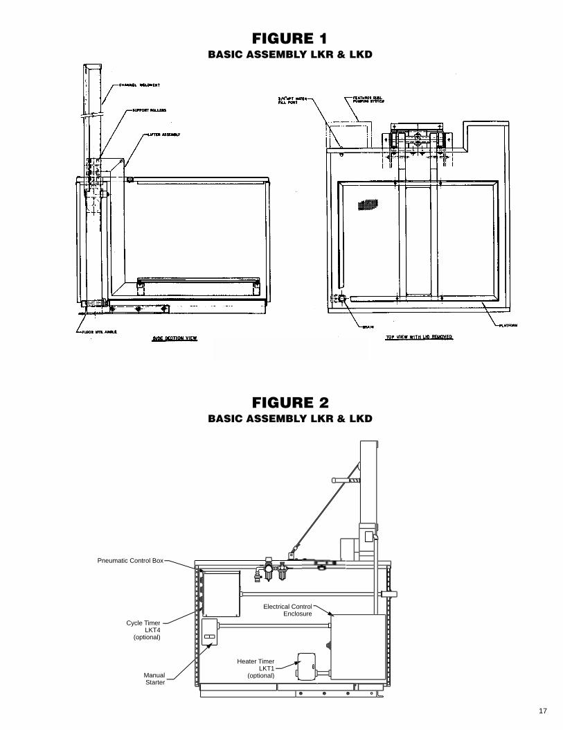
CONSTRUCTION FEATURESThe general arrangements of the Models LKR andLKD Liftkleen assemblies, including optionalfeatures, are shown in Figures 1 and 2. Thefollowing paragraphs describe specificconstruction details.
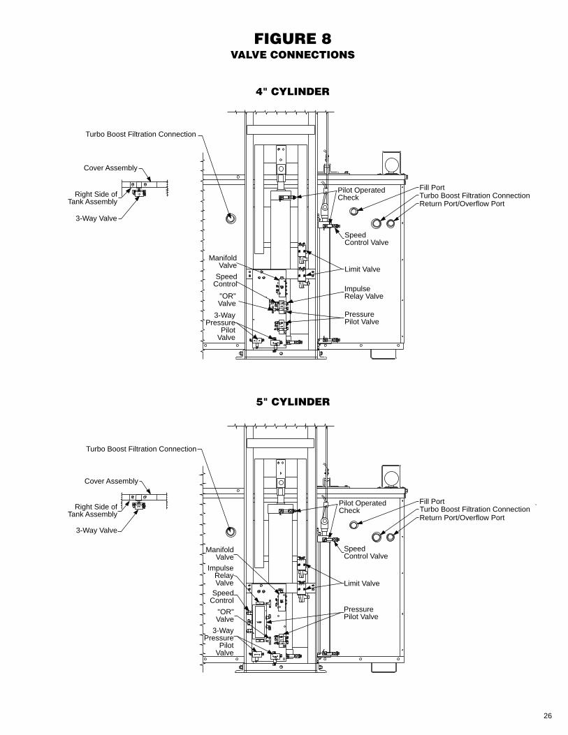
• TANK ASSEMBLYThe Liftkleen was designed to withstand therugged demands of heavy-duty industrial andautomotive parts cleaning. The tank is leak-tested after welding. The bottom of the tankutilizes double wall construction and issupported by four channels. Openings areprovided to facilitate moving the Liftkleen witha fork-lift truck. A 1-1/2” NPT drain is locatedin the bottom of the tank to which permanentdrain connections can be attached. Anoverflow port is part of the tank assembly andis intended for use with heated models only.A water fill port is located in the rear of thetank (see Figure 8) and consists of 3/4” NPTpipe nipple. On optional heated models, thetank sides and cover are insulated with 1”thick polystyrene foam (equal to two-plusinches of fiberglass).
• PLATFORM AND LIFTER ASSEMBLYThe Platform and Lifter Assembly aredesigned to handle loads specified for theparticular model of Liftkleen (see Table 2).The platform consists of an angle iron framewhich supports an open steel grate. The lifterassembly is made up of a channel weldment,platform support weldment, four supportrollers with needle bearings and hardenedshafts, and a pneumatic cylinder. (Airconsumption data can be found in Table 3).
The rollers and bearings on all Model LKRand LKD units are located outside the tankand therefore never immersed in the cleaningsolution. This helps keep moving partslubricated. The standard open steel grate ofthe platform assembly can be replaced withthe optional roller conveyor platform.
• PUMP ASSEMBLYThe Superflo Pumping Unit Assembly, anavailable option on all Model LKR and LKDunits, is capable of providing 10,000 gallonsper hour of flow and provides exceptionalliquid agitation for quicker, more effectiveparts cleaning. It is especially effective onparts containing holes. The pump is acentrifugal unit and is driven by an electricmotor.
4
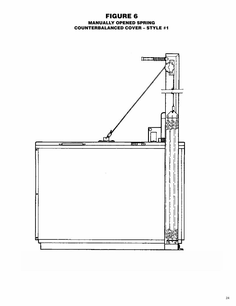
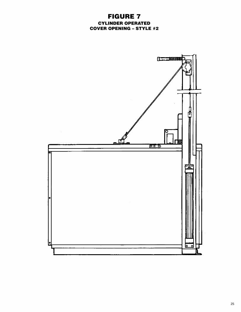
• COVER ASSEMBLYThe internal cover is made of stainless steelto eliminate corrosion caused by vaporcondensation. On heated models, openingand closing the lid is accomplished manuallyutilizing a counter balanced lid (Figure 6). Anoptional pneumatically powered lid isavailable on heated units (Figure 7). Lids, aswell as tanks, are insulated on heated units.
Unheated units must be ordered with apneumatically powered lid (Figure 7). The lidactuation system on these units contains atemperature sensitive automatic closingfeature. In the event of a fire in the tank, theplatform assembly lowers and the lid closesautomatically.
WARNINGAlways stand clear of lid. To prevent injury,keep head, hands and body clear of the lid, liftplatform and lift mechanism at all times. Theseunits have moving parts, pinch-points andclose tolerances. Always stand clear of the liftplatform and lid when operating as the lidcould unexpectedly open or the platformoperate. Keep hands and fingers away fromtank when operating platform.
CAUTIONWhen turning air on or off or when operatingthe lift platform, stay clear of the lid, liftplatform and operating mechanism as the lidcould unexpectedly open or the platformoperate.
• PNEUMATIC CONTROLSThe standard Liftkleen is furnished with apneumatic system that raises and lowers theplatform, a master on/off valve and afilter/regulator/ lubricator unit.
The agitating lift platform contains aircontrols that agitate the platform up anddown through a range of five inches with avariable frequency of 20 to 40 strokes perminute. Stroke frequency depends on loadand available air pressure. Adjustments tothe system should be made under operatingload conditions.
The platform agitation system consists of acontrol box with a 2-position oscillationswitch, a start and a restart switch, a masteron/off valve, a filter/regulator/lubricator unit, apilot operated directional control valve andtwo limit valves.
!
!
The optional pneumatically opened lid controlis incorporated with the platform agitationsystem.
Schematics and operation sequence sheetsare presented in Figures 4a through 4c.
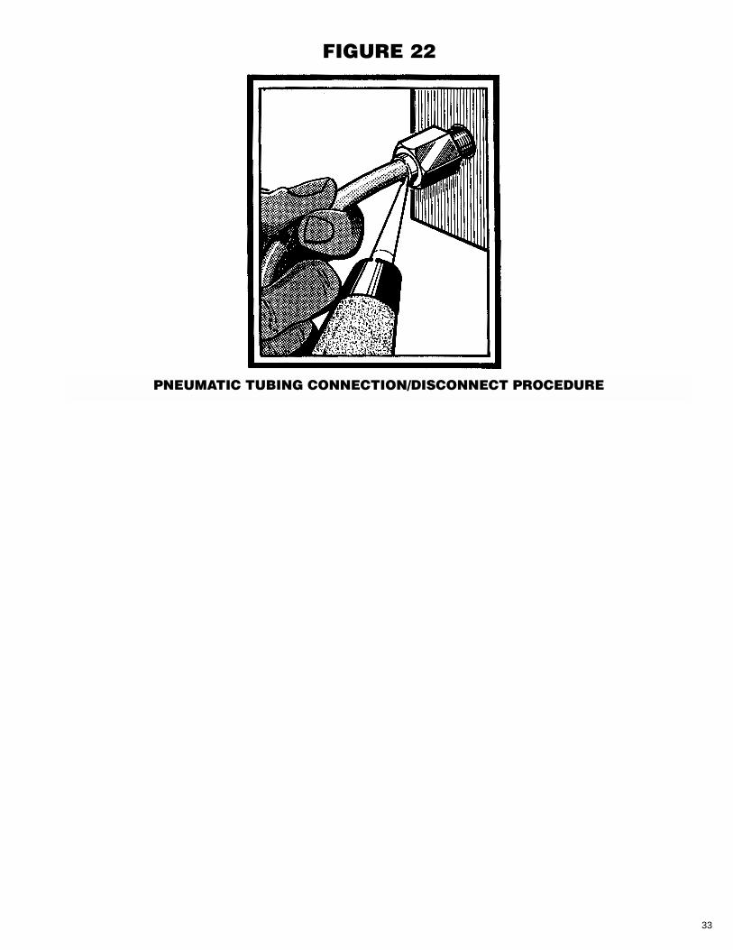
All pneumatic tubing connections are madewith Instant Fittings. These make it possibleto connect and disconnect the tubing to thefittings without the use of a wrench. Todisconnect a tube, simply push in the brassor plastic collet with a screwdriver tip and pullthe tube from the socket. To engage the tube,push it into the fitting until it hits the stop.Sealing of the connection is achieved with anO-Ring in the fitting. This procedure is shownin detail in Figure 22.
The air cylinder for raising, lowering andoscillating (agitating) the work platform haspneumatic lines connected to both its “up”and “down” ports. This provides for smooth,positive, controlled motion in both traveldirections with minimal dependence on theweight of the work load.
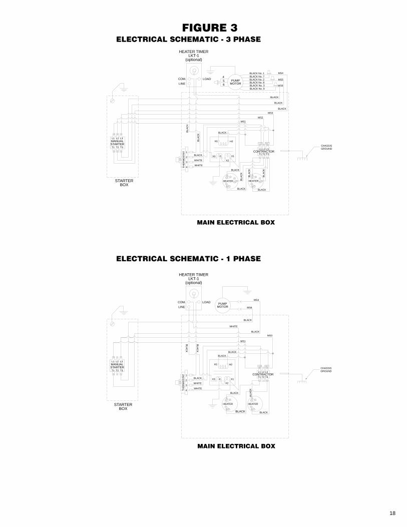
• ELECTRIC CONTROLSElectrical controls are required on all unitswhich have pumps, electric heat or steamheat. Models equipped with optional Superflopump assemblies come equipped with amanual motor starter and thermal overloadprotection. Electrically heated models areequipped with from one to four stainless steel4.5 KW electric, immersion-type heaters, athermostat and contactor. Refer to Table 4 forthe amperage requirements of LiftkleenElectric Heaters and Pump Motors.
Insulation is added to the tank sides and topon all heated models. This insulation consistsof one inch thick polyurethane foam.
5
INSTALLATION
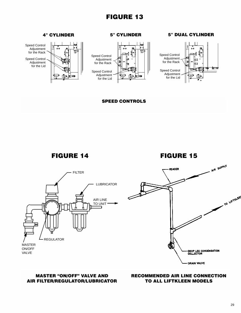
• SERVICE HOOK-UPAIRUnits are supplied with a Lockable Air Switchconnection. Connect an air supply line to theinlet of the master on/off valve located on theside of the machine (see Figure 14). Therecommended air piping arrangement shouldbe followed to assure trouble-free operation(see Figure 15). Once your line is connected,make sure the air switch sleeve is fullyengaged to ensure proper air supply.
Note: The minimum operating air pressure is85 PSI, however, operating at this pressuregreatly reduces the lift capacity of the unit.We recommend operating the unit at 90-100PSI for optimal performance. Maximum inletpressure is 110 PSI. A pressure gauge isprovided on the filter/regulator/lubricatorwhich is located on the side of the Liftkleenwasher next to the Air Switch Connection.
ELECTRIC
• On Liftkleen models with Superflo PumpAssembly only, a junction box is providedon the side of the unit for hook-up with theappropriate electrical service.
• On Liftkleen models with electric heatonly, an electrical enclosure is provided.The attachment points on the contactor areappropriately marked.
• On Liftkleen models with both SuperfloPump Assembly and electric heat, anelectrical enclosure containing a contactoris provided. Connections on the contactorare appropriately marked.
WARNINGThe Liftkleen must be properly grounded.
CAUTIONCheck the electrical specifications on thenameplate to assure the proper connections.On 3 phase models equipped with a Superflopump, make sure that the motor rotation iscorrect; that is, counter clockwise whenviewed from the top. To reverse rotation,switch any two of the 3 phase leads.
DRAIN – A 1-1/2˝ NPT female drain islocated on the bottom of the tank assembly. Aplug is installed at the factory. To makeconnections to the drain, remove the plug
!
!
and install appropriate plumbing. It issuggested that a shut-off valve be installed.
WATER SUPPLY – A 3/4˝ NPT pipe nipple isfurnished at the rear of the Liftkleen asshown on Figure 8. This is intended as a con-nection to a water source for filling tank ormake up supply for heated Liftkleen models.
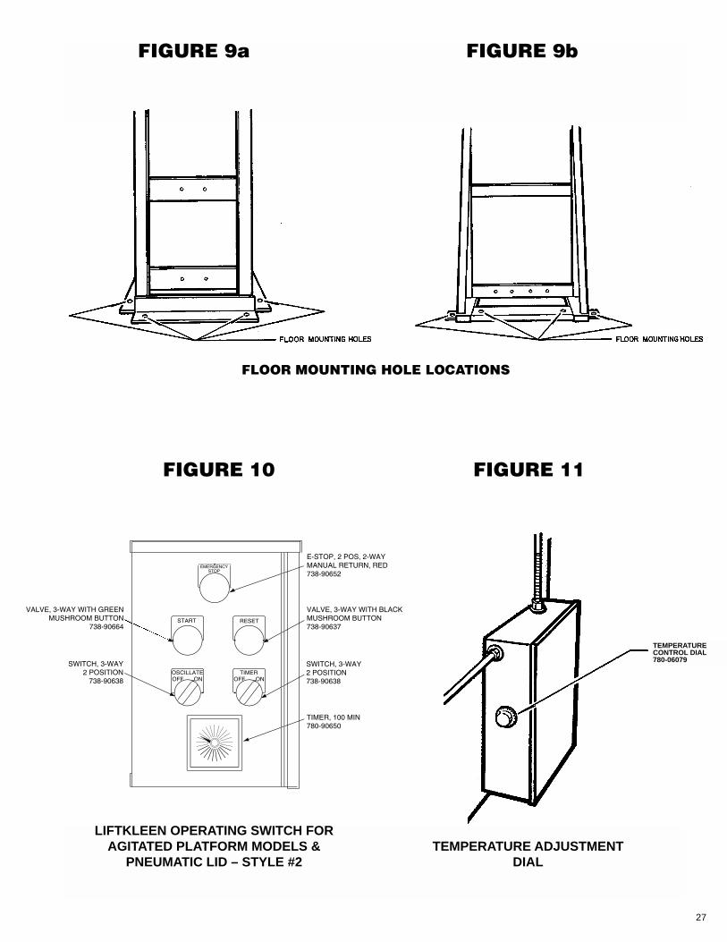
• FLOOR MOUNTING OF LIFTKLEENFour (4) mounting holes for anchoring theModels LKR and LKD Liftkleen to the floorare located in the bottom of the channelweldment assembly at the rear of themachine (see Figures 9a,b). These holesaccommodate 1/2˝ diameter bolts. Themachine must be anchored to the floor atthese points. Failure to adequately anchorthe unit will affect its lifting capacity and/orcause structural damage to the machine.
OPERATIONWARNING
Always stand clear of lid. To prevent injury,keep head, hands and body clear of the lid, liftplatform and lift mechanism at all times. Theseunits have moving parts, pinch-points andclose tolerances. Always stand clear of the liftplatform and lid when operating as the lidcould unexpectedly open or the platformoperate. Keep hands and fingers away fromtank when operating platform.
• AGITATING LIFT PLATFORMTo operate the unit, first open the lid. On unitsequipped with the pneumatically operatedlid, this is done automatically during the nextstep. Press the "RESET" button. Theplatform will rise to the top of the unit and isnow ready for loading. Please note, theplatform will not rise until the lid is fully open.
Once loaded, rotate the Oscillate SelectorSwitch to the "ON" position. Press the"START" button. Platform will descend todown position and remain there until lid isclosed. Upon lid closure, the platform willbegin to oscillate and will continue to do sountil the operator depresses the "RESET"button or rotates the Oscillate SelectorSwitch to the "OFF" position. Be sure to openlid when resetting platform. The platform willnot oscillate unless lid is closed. Those unitsequipped with a pneumatically operated lidwill close automatically. If soaking is desired,
!
6
rotate the Oscillate Selector Switch to the"OFF" position. Once the "START" button ispressed, the unit will lower and stop in thefully down position and will remain idle untilthe operator depresses the "RESET" buttonor rotates the Oscillate Selector Switch to the"ON" position.
• CYCLE TIMER (OPTIONAL)This option allows the operator to set thelength of time of the cleaning cycle. Toactuate the timer, turn the Timer SelectorSwitch to the "On" position. Set the timer tothe desired cycle time, depress the "Start"button to begin the sequence. The platformwill agitate for the preset time after which itwill rise along with the lid to an Up/Openposition for the start of the next cycle. TurnTimer Selector Switch to the "Off" positionwhen manual operation is desired.
Note: The Cycle Timer is only available onunits with automatically operated lids.(LKR & LKD units)
• EMERGENCY STOPThe unit includes an E-Stop feature which willshut down all pneumatic operation whendepressed and should be used in emergencysituations only. Once the obstruction/problemis corrected the switch can be reset by simplylifting the button back into its original position.
• ANTI-TIE DOWN DEVICE (OPTIONAL)This device protects the operator frompotential situations where contact with apinch point on the machine can occur. Thefunction of this device replaces the "START"button in the preceding sequence instructionsand will require the operator to depress twobuttons simultaneously and hold them untilthe lid is resting in the closed position. Theunit will then function normally as describedin the previous operational instructions.
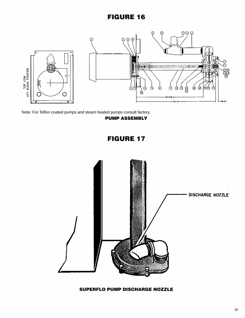
• SUPERFLO PUMP (OPTIONAL)A manual starter is provided to enable theoperator to turn the pump on when pump agi-tation is desired. If the optional filtrationsystem is selected, the pump must beoperated to create the filtration process. Thegeneral arrangement of a pump assembly isshown in Figure 16. For wiring schematic,see Figure 3.
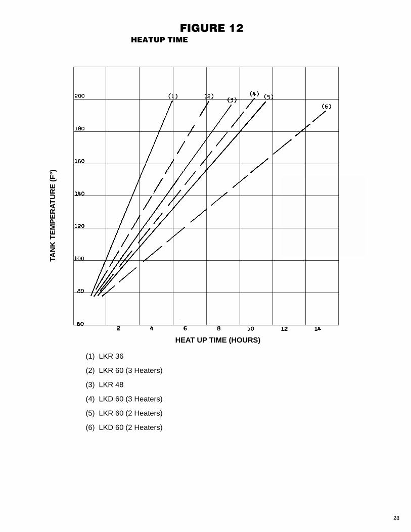
• ELECTRIC HEAT (OPTIONAL, AQUEOUSUNITS ONLY)Heaters are automatically turned on and offby the thermostat (Figure 11) to maintain thedesired tank temperature. The thermostat isadjusted by rotating the dial over its indicatedrange of 60°F to 180°F. The heaters can beshut off by setting the thermostat to the “Off”position. Figure 12 contains data regardingheat-up time for the various Liftkleen models.For wiring schematic, see Figure 3.
Operating temperature should not exceed180°F.
Note: Never operate heaters unless they arecompletely covered by liquid.
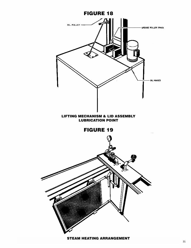
• STEAM HEAT (OPTIONAL)Liftkleens are available with optional steamheat. This option comes complete with a ther-mostat and all necessary plumbing andrequires the hook-up of the steam supply andcondensate lines along with the connection ofa 115V electrical supply to the thermostat.
• HEATER TIMER (OPTIONAL)The LKT-1 Heater Timer is available on allheated Liftkleen units. This option allows theoperator to preset both the heater startuptime and the length of time the heater is inoperation each day. The timer also features a“day skipper” feature which allows the unit toremain off on weekends, lowering heatingcosts.
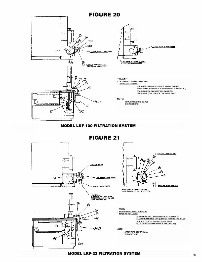
• LIFTKLEEN FILTRATION SYSTEMS(OPTIONAL)Filtration systems are available on allLiftkleen models featuring pump agitation.The system consists of standard, single ordual filters and a selection of filter elements.
Model LKF-100 (Figure 20) is a singlecartridge filter. Model LKF-22 (Figure 21) is adual cartridge unit. Model LKF-100 isequipped with a 100 mesh (150 micron)Cylinder Strainer Cartridge. This filtercartridge is made of stainless steel, with finewire mesh reinforced with perforated metal.The LKF-200 dual filter unit is complete witha primary 30 mesh (590 micron) cartridgecylinder and a 100 mesh (150 micron)secondary cartridge cylinder. Cartridgeslisted in Table 5 may be interchanged withstandard ones.
7
8
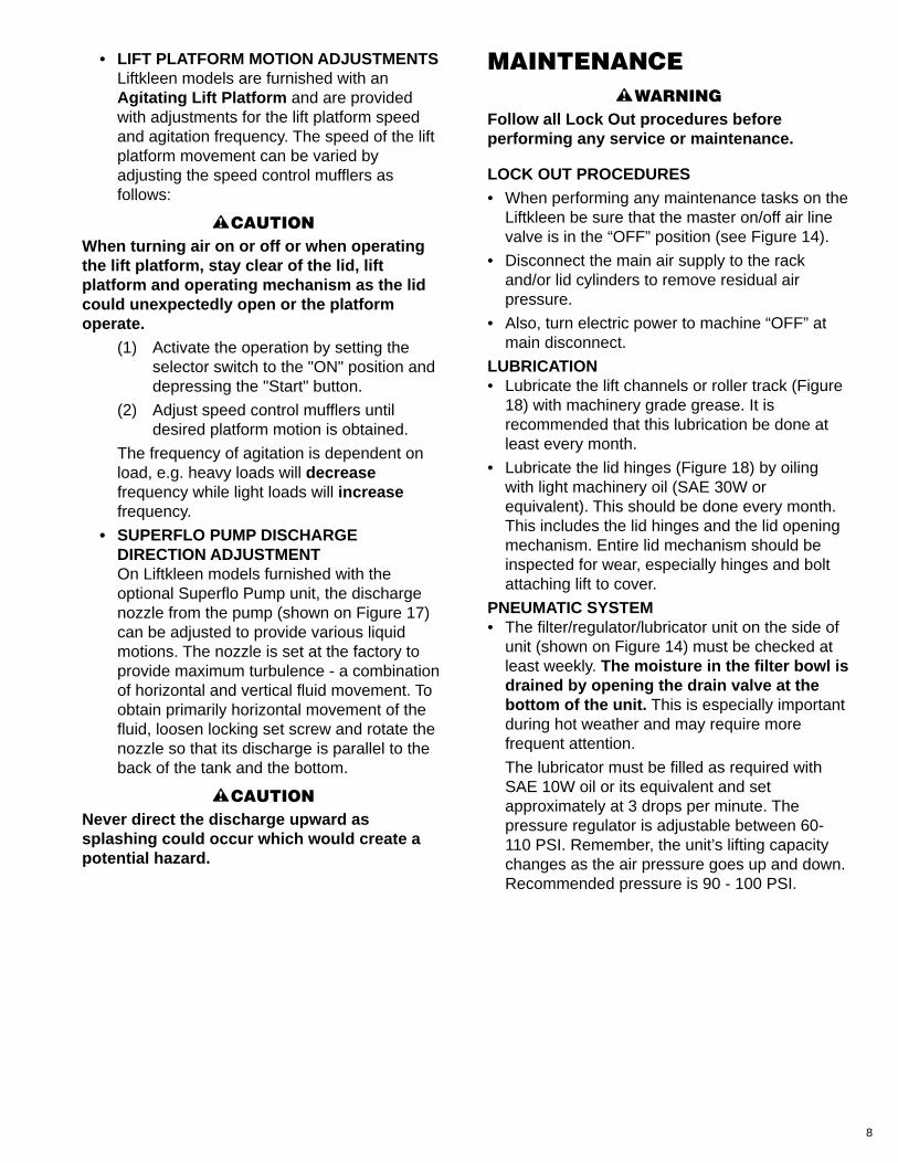
• LIFT PLATFORM MOTION ADJUSTMENTSLiftkleen models are furnished with anAgitating Lift Platform and are providedwith adjustments for the lift platform speedand agitation frequency. The speed of the liftplatform movement can be varied byadjusting the speed control mufflers asfollows:
CAUTIONWhen turning air on or off or when operatingthe lift platform, stay clear of the lid, liftplatform and operating mechanism as the lidcould unexpectedly open or the platformoperate.
(1) Activate the operation by setting theselector switch to the "ON" position anddepressing the "Start" button.
(2) Adjust speed control mufflers untildesired platform motion is obtained.
The frequency of agitation is dependent onload, e.g. heavy loads will decreasefrequency while light loads will increasefrequency.
• SUPERFLO PUMP DISCHARGEDIRECTION ADJUSTMENTOn Liftkleen models furnished with theoptional Superflo Pump unit, the dischargenozzle from the pump (shown on Figure 17)can be adjusted to provide various liquidmotions. The nozzle is set at the factory toprovide maximum turbulence - a combinationof horizontal and vertical fluid movement. Toobtain primarily horizontal movement of thefluid, loosen locking set screw and rotate thenozzle so that its discharge is parallel to theback of the tank and the bottom.
CAUTIONNever direct the discharge upward assplashing could occur which would create apotential hazard.
!
!
MAINTENANCEWARNING
Follow all Lock Out procedures beforeperforming any service or maintenance.
LOCK OUT PROCEDURES• When performing any maintenance tasks on the
Liftkleen be sure that the master on/off air linevalve is in the “OFF” position (see Figure 14).
• Disconnect the main air supply to the rackand/or lid cylinders to remove residual airpressure.
• Also, turn electric power to machine “OFF” atmain disconnect.
LUBRICATION• Lubricate the lift channels or roller track (Figure
18) with machinery grade grease. It isrecommended that this lubrication be done atleast every month.
• Lubricate the lid hinges (Figure 18) by oilingwith light machinery oil (SAE 30W orequivalent). This should be done every month.This includes the lid hinges and the lid openingmechanism. Entire lid mechanism should beinspected for wear, especially hinges and boltattaching lift to cover.
PNEUMATIC SYSTEM• The filter/regulator/lubricator unit on the side of
unit (shown on Figure 14) must be checked atleast weekly. The moisture in the filter bowl isdrained by opening the drain valve at thebottom of the unit. This is especially importantduring hot weather and may require morefrequent attention.
The lubricator must be filled as required withSAE 10W oil or its equivalent and setapproximately at 3 drops per minute. Thepressure regulator is adjustable between 60-110 PSI. Remember, the unit’s lifting capacitychanges as the air pressure goes up and down.Recommended pressure is 90 - 100 PSI.
!
9
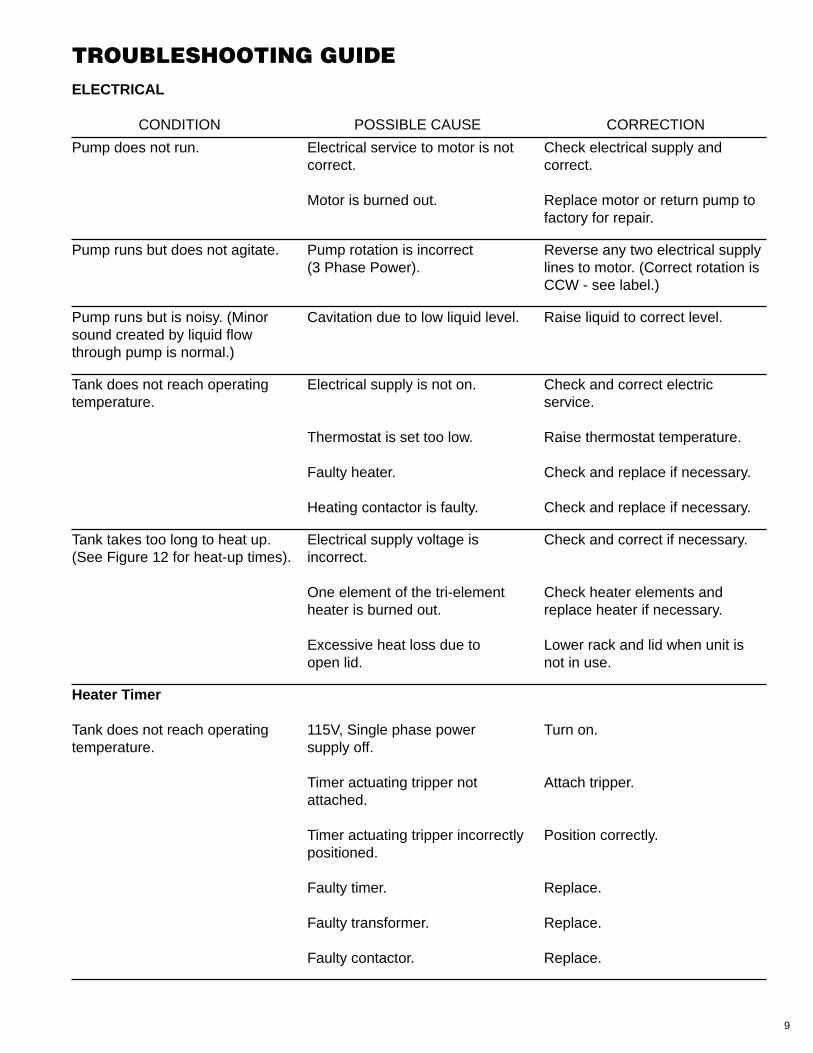
TROUBLESHOOTING GUIDEELECTRICAL
CONDITION POSSIBLE CAUSE CORRECTION
Pump does not run. Electrical service to motor is not Check electrical supply and correct. correct.
Motor is burned out. Replace motor or return pump tofactory for repair.
Pump runs but does not agitate. Pump rotation is incorrect Reverse any two electrical supply(3 Phase Power). lines to motor. (Correct rotation is
CCW - see label.)
Pump runs but is noisy. (Minor Cavitation due to low liquid level. Raise liquid to correct level.sound created by liquid flowthrough pump is normal.)
Tank does not reach operating Electrical supply is not on. Check and correct electric temperature. service.
Thermostat is set too low. Raise thermostat temperature.
Faulty heater. Check and replace if necessary.
Heating contactor is faulty. Check and replace if necessary.
Tank takes too long to heat up. Electrical supply voltage is Check and correct if necessary.(See Figure 12 for heat-up times). incorrect.
One element of the tri-element Check heater elements and heater is burned out. replace heater if necessary.
Excessive heat loss due to Lower rack and lid when unit isopen lid. not in use.
Heater Timer
Tank does not reach operating 115V, Single phase power Turn on.temperature. supply off.
Timer actuating tripper not Attach tripper.attached.
Timer actuating tripper incorrectly Position correctly.positioned.
Faulty timer. Replace.
Faulty transformer. Replace.
Faulty contactor. Replace.

10
Cycle Timer
Platform oscillates but does not Lid cylinder fails to operate. Check and manually activate.raise automatically after cycle.
Solenoid valve stuck. (Only on Clean or replace.LKT-3)
Solenoid inoperative. Replace after checking electricalcharacteristics.
Platform does not agitate. Solenoid valve stuck. (Only on Clean or replace.LKT-3)
Solenoid inoperative. (Only on Replace after checking electrical LKT-3) characteristics.
Faulty air valve. Replace.
Faulty timer. Replace.
PNEUMATIC
Lift platform is jammed. Parts lodged in lifter mechanism. Reverse unit and remove parts.
Platform does not operate Air supply is not connected. Check and connect air supply.properly.
Master on/off valve is in “OFF” Turn to “ON” position.position.
Main air pressure regulator set Adjust regulator to 80 psi too low. minimum.
Speed control mufflers adjusted Correct adjustment.incorrectly.
Pneumatic air control supply line Check and repair as required.pinched or disconnected.
CONDITION POSSIBLE CAUSE CORRECTION
11
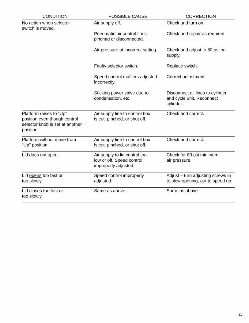
No action when selector Air supply off. Check and turn on.switch is moved.
Pneumatic air control lines Check and repair as required.pinched or disconnected.
Air pressure at incorrect setting. Check and adjust to 80 psi onsupply.
Faulty selector switch. Replace switch.
Speed control mufflers adjusted Correct adjustment.incorrectly.
Sticking power valve due to Disconnect all lines to cylindercondensation, etc. and cycle unit. Reconnect
cylinder.
Platform raises to “Up” Air supply line to control box Check and correct.position even though control is cut, pinched, or shut off.selector knob is set at anotherposition.
Platform will not move from Air supply line to control box Check and correct.“Up” position. is cut, pinched, or shut off.
Lid does not open. Air supply to lid control too Check for 80 psi minimumlow or off. Speed control air pressure.improperly adjusted.
Lid opens too fast or Speed control improperly Adjust – turn adjusting screws intoo slowly. adjusted. to slow opening, out to speed up.
Lid closes too fast or Same as above. Same as above.too slowly.
CONDITION POSSIBLE CAUSE CORRECTION
12
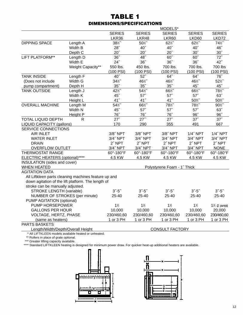
TABLE 1DIMENSIONS/SPECIFICATIONS
MODELS*SERIES SERIES SERIES SERIES SERIESLKR36 LKR48 LKR60 LKD60 LKD72
DIPPING SPACE Length A 381⁄2˝ 501⁄2˝ 621⁄2˝ 621⁄2˝ 741⁄2˝Width B 28˝ 40˝ 40˝ 40˝ 46˝Depth C 20˝ 20˝ 20˝ 30˝ 30˝
LIFT PLATFORM** Length D 36˝ 48˝ 60˝ 60˝ 72˝Width E 24˝ 36˝ 36˝ 36˝ 42˝Weight Capacity** 550 lbs. 450 lbs. 700 lbs. 700 lbs. 700 lbs
(100 PSI) (100 PSI) (100 PSI) (100 PSI) (100 PSI)TANK INSIDE Length F 40˝ 52˝ 64˝ 64˝ 76˝(Does not include Width G 341⁄2˝ 461⁄2˝ 461⁄2˝ 461⁄2˝ 521⁄2˝pump compartment) Depth H 35˝ 35˝ 35˝ 45˝ 45˝
TANK OUTSIDE Length J 421⁄2˝ 541⁄2˝ 661⁄2˝ 661⁄2˝ 781⁄2˝Width K 45˝ 57˝ 57˝ 57˝ 63˝Height L 41˝ 41˝ 41˝ 503⁄4˝ 503⁄4˝
OVERALL MACHINE Length M 541⁄2˝ 661⁄2˝ 781⁄2˝ 781⁄2˝ 901⁄2˝Width N 45˝ 57˝ 57˝ 57˝ 63˝Height P 76˝ 76˝ 76˝ 96˝ 96˝
TOTAL LIQUID DEPTH R 27˝ 27˝` 27˝ 37˝ 37˝LIQUID CAPACITY (gallons) 170 290 355 491 667SERVICE CONNECTIONS
AIR INLET 3/8˝ NPT 3/8˝ NPT 3/8˝ NPT 1/4˝ NPT 1/4˝ NPTWATER INLET 3/4˝ NPT 3/4˝ NPT 3/4˝ NPT 3/4˝ NPT 3/4˝ NPTDRAIN 2˝ NPT 2˝ NPT 2˝ NPT 2˝ NPT 2˝ NPTOVERFLOW OUTLET 3/4˝ NPT 3/4˝ NPT 3/4˝ NPT 3/4˝ NPT NONE
THERMOSTAT RANGE 60°-180°F 60°-180°F 60°-180°F 60°-180°F 60°-180°FELECTRIC HEATERS (optional)**** 4.5 KW 4.5 KW 4.5 KW 4.5 KW 4.5 KWINSULATION (sides and cover)WHEN HEATED Polystyrene Foam - 1˝ ThickAGITATION DATA
All Liftkleen parts cleaning machines feature up anddown agitation of the lift platform. The length ofstroke can be manually adjusted.
STROKE LENGTH (variable) 3˝-5˝ 3˝-5˝ 3˝-5˝ 3˝-5˝ 3˝-5˝NUMBER OF STROKES (per minute) 25-40 25-40 25-40 25-40 25-40
PUMP AGITATION (optional)PUMP HORSEPOWER 11⁄2 11⁄2 11⁄2 11⁄2 11⁄2 ((2 pumps)
GALLONS PER HOUR 10,000 10,000 10,000 10,000 20,000VOLTAGE, HERTZ, PHASE 230/460,60 230/460,60 230/460,60 230/460,60 230/460,60
(same as heaters) 1 or 3 PH 1 or 3 PH 1 or 3 PH 1 or 3 PH 1 or 3 PHPARTS BASKETS
Length/Width/Depth/Overall Height CONSULT FACTORY* All LIFTKLEEN models available heated or unheated.
** Rollers in place of grate optional.*** Greater lifting capacity available.
**** Standard LIFTKLEEN heating is designed for minimum power draw. For quicker heat-up additional heaters are available.
13
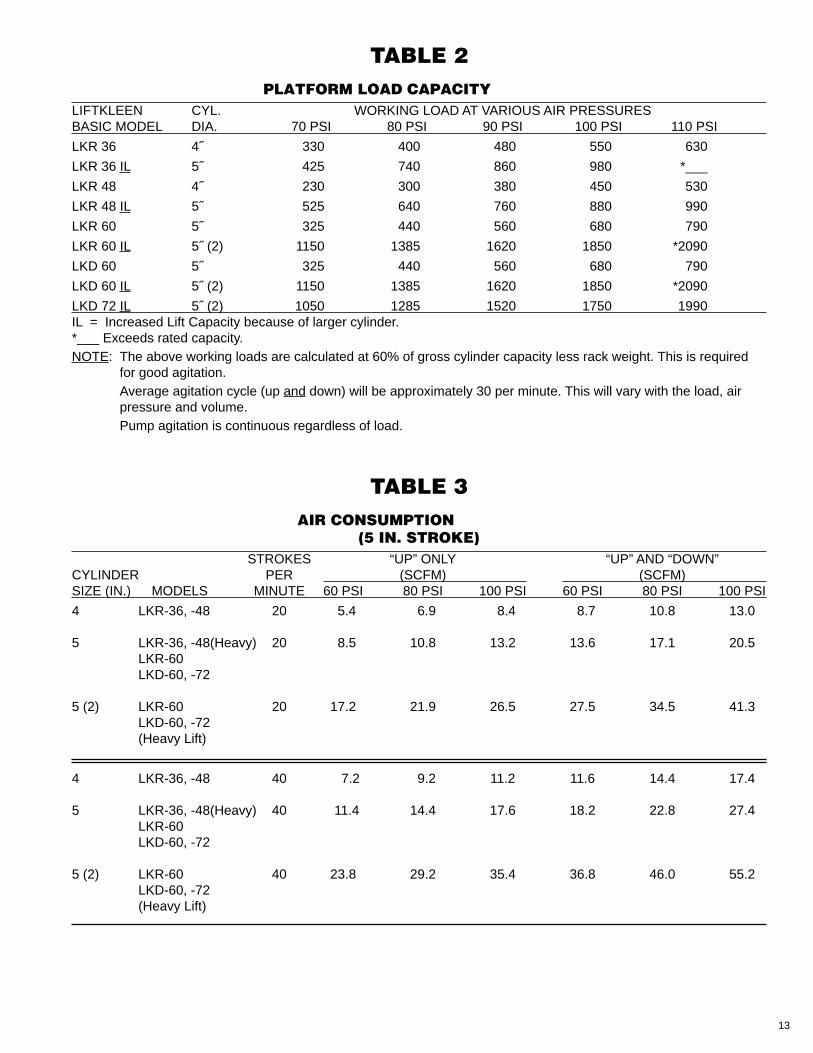
TABLE 2 PLATFORM LOAD CAPACITY
LIFTKLEEN CYL. WORKING LOAD AT VARIOUS AIR PRESSURESBASIC MODEL DIA. 70 PSI 80 PSI 90 PSI 100 PSI 110 PSI
LKR 36 4˝ 330 400 480 550 630
LKR 36 IL 5˝ 425 740 860 980 *___
LKR 48 4˝ 230 300 380 450 530
LKR 48 IL 5˝ 525 640 760 880 990
LKR 60 5˝ 325 440 560 680 790
LKR 60 IL 5˝ (2) 1150 1385 1620 1850 *2090
LKD 60 5˝ 325 440 560 680 790
LKD 60 IL 5˝ (2) 1150 1385 1620 1850 *2090
LKD 72 IL 5˝ (2) 1050 1285 1520 1750 1990IL = Increased Lift Capacity because of larger cylinder.*___ Exceeds rated capacity.NOTE: The above working loads are calculated at 60% of gross cylinder capacity less rack weight. This is required
for good agitation.Average agitation cycle (up and down) will be approximately 30 per minute. This will vary with the load, airpressure and volume.Pump agitation is continuous regardless of load.
TABLE 3 AIR CONSUMPTION
(5 IN. STROKE)STROKES “UP” ONLY “UP” AND “DOWN”
CYLINDER PER (SCFM) (SCFM)SIZE (IN.) MODELS MINUTE 60 PSI 80 PSI 100 PSI 60 PSI 80 PSI 100 PSI
4 LKR-36, -48 20 5.4 6.9 8.4 8.7 10.8 13.0
5 LKR-36, -48(Heavy) 20 8.5 10.8 13.2 13.6 17.1 20.5LKR-60LKD-60, -72
5 (2) LKR-60 20 17.2 21.9 26.5 27.5 34.5 41.3LKD-60, -72(Heavy Lift)
4 LKR-36, -48 40 7.2 9.2 11.2 11.6 14.4 17.4
5 LKR-36, -48(Heavy) 40 11.4 14.4 17.6 18.2 22.8 27.4LKR-60LKD-60, -72
5 (2) LKR-60 40 23.8 29.2 35.4 36.8 46.0 55.2LKD-60, -72(Heavy Lift)
14
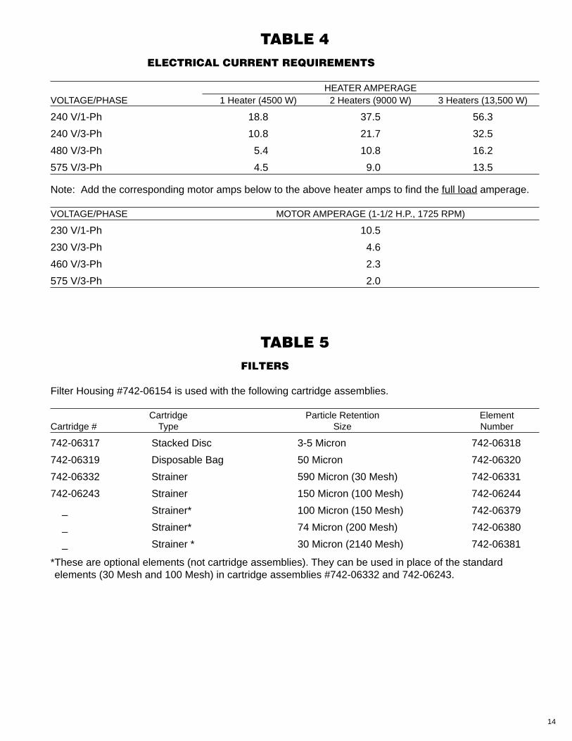
TABLE 4ELECTRICAL CURRENT REQUIREMENTS
HEATER AMPERAGEVOLTAGE/PHASE 1 Heater (4500 W) 2 Heaters (9000 W) 3 Heaters (13,500 W)
240 V/1-Ph 18.8 37.5 56.3
240 V/3-Ph 10.8 21.7 32.5
480 V/3-Ph 5.4 10.8 16.2
575 V/3-Ph 4.5 9.0 13.5
Note: Add the corresponding motor amps below to the above heater amps to find the full load amperage.
VOLTAGE/PHASE MOTOR AMPERAGE (1-1/2 H.P., 1725 RPM)
230 V/1-Ph 10.5
230 V/3-Ph 4.6
460 V/3-Ph 2.3
575 V/3-Ph 2.0
TABLE 5 FILTERS
Filter Housing #742-06154 is used with the following cartridge assemblies.
Cartridge Particle Retention ElementCartridge # Type Size Number
742-06317 Stacked Disc 3-5 Micron 742-06318
742-06319 Disposable Bag 50 Micron 742-06320
742-06332 Strainer 590 Micron (30 Mesh) 742-06331
742-06243 Strainer 150 Micron (100 Mesh) 742-06244
_ Strainer* 100 Micron (150 Mesh) 742-06379
_ Strainer* 74 Micron (200 Mesh) 742-06380
_ Strainer * 30 Micron (2140 Mesh) 742-06381
*These are optional elements (not cartridge assemblies). They can be used in place of the standardelements (30 Mesh and 100 Mesh) in cartridge assemblies #742-06332 and 742-06243.
15
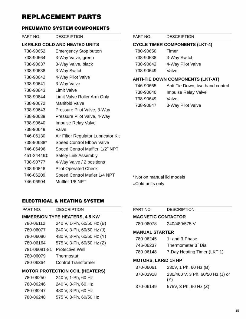
PNEUMATIC SYSTEM COMPONENTS
PART NO. DESCRIPTION PART NO. DESCRIPTION
LKR/LKD COLD AND HEATED UNITS738-90652 Emergency Stop button
738-90664 3-Way Valve, green
738-90637 3-Way Valve, black
738-90638 3-Way Switch
738-90642 4-Way Pilot Valve
738-90641 3-Way Valve
738-90843 Limit Valve
738-90844 Limit Valve Roller Arm Only
738-90672 Manifold Valve
738-90643 Pressure Pilot Valve, 3-Way
738-90639 Pressure Pilot Valve, 4-Way
738-90640 Impulse Relay Valve
738-90649 Valve
746-06130 Air Filter Regulator Lubricator Kit
738-90688* Speed Control Elbow Valve
746-06496 Speed Control Muffler, 1/2˝ NPT
451-24446‡ Safety Link Assembly
738-90777 4-Way Valve / 2 positions
738-90848 Pilot Operated Check
746-06209 Speed Control Mufler 1/4 NPT
746-06904 Muffler 1/8 NPT
CYCLE TIMER COMPONENTS (LKT-4)780-90650 Timer
738-90638 3-Way Switch
738-90642 4-Way Pilot Valve
738-90649 Valve
ANTI-TIE DOWN COMPONENTS (LKT-AT)746-90655 Anti-Tie Down, two hand control
738-90640 Impulse Relay Valve
738-90649 Valve
738-90847 3-Way Pilot Valve
* Not on manual lid models
‡Cold units only
REPLACEMENT PARTS
ELECTRICAL & HEATING SYSTEM
IMMERSION TYPE HEATERS, 4.5 KW780-06112 240 V, 1-Ph, 60/50 Hz (B)
780-06077 240 V, 3-Ph, 60/50 Hz (J)
780-06080 480 V, 3-Ph, 60/50 Hz (Y)
780-06164 575 V, 3-Ph, 60/50 Hz (Z)
781-06081-81 Protective Well
780-06079 Thermostat
780-06364 Control Transformer
MOTOR PROTECTION COIL (HEATERS)780-06250 240 V, 1-Ph, 60 Hz
780-06246 240 V, 3-Ph, 60 Hz
780-06247 480 V, 3-Ph, 60 Hz
780-06248 575 V, 3-Ph, 60/50 Hz
MAGNETIC CONTACTOR
780-06078 240/480/575 V
MANUAL STARTER780-06245 1- and 3-Phase
746-06237 Thermometer 3˝ Dial
780-06148 7-Day Heating Timer (LKT-1)
MOTORS, LKR/D 11⁄2 HP
370-06061 230V, 1 Ph, 60 Hz (B)
370-03918 230/460 V, 3 Ph, 60/50 Hz (J) or(Y)
370-06149 575V, 3 Ph, 60 Hz (Z)
PART NO. DESCRIPTION PART NO. DESCRIPTION
16
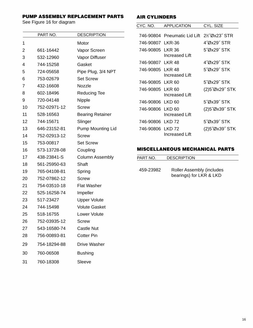
PART NO. DESCRIPTION
PART NO. DESCRIPTION
1 Motor
2 661-16442 Vapor Screen
3 532-12960 Vapor Diffuser
4 744-15258 Gasket
5 724-05658 Pipe Plug, 3/4 NPT
6 753-02679 Set Screw
7 432-16608 Nozzle
8 602-18496 Reducing Tee
9 720-04148 Nipple
10 752-02971-12 Screw
11 528-16563 Bearing Retainer
12 744-15671 Slinger
13 646-23152-81 Pump Mounting Lid
14 752-02913-12 Screw
15 753-00817 Set Screw
16 573-13728-08 Coupling
17 438-23841-S Column Assembly
18 561-25950-63 Shaft
19 765-04108-81 Spring
20 752-07862-12 Screw
21 754-03510-18 Flat Washer
22 525-16258-74 Impeller
23 517-23427 Upper Volute
24 744-15498 Volute Gasket
25 518-16755 Lower Volute
26 752-03935-12 Screw
27 543-16580-74 Castle Nut
28 756-00893-81 Cotter Pin
29 754-18294-88 Drive Washer
30 760-06508 Bushing
31 760-18308 Sleeve
746-90804 Pneumatic Lid Lift 21⁄2˝Øx23˝ STR
746-90807 LKR-36 4˝Øx29˝ STR
746-90805 LKR 36 5˝Øx29˝ STKIncreased Lift
746-90807 LKR 48 4˝Øx29˝ STK
746-90805 LKR 48 5˝Øx29˝ STKIncreased Lift
746-90805 LKR 60 5˝Øx29˝ STK
746-90805 LKR 60 (2)5˝Øx29˝ STKIncreased Lift
746-90806 LKD 60 5˝Øx39˝ STK
746-90806 LKD 60 (2)5˝Øx39˝ STKIncreased Lift
746-90806 LKD 72 5˝Øx39˝ STK
746-90806 LKD 72 (2)5˝Øx39˝ STKIncreased Lift
459-23982 Roller Assembly (includesbearings) for LKR & LKD
PUMP ASSEMBLY REPLACEMENT PARTSSee Figure 16 for diagram
MISCELLANEOUS MECHANICAL PARTS
CYC. NO. APPLICATION CYL. SIZE
AIR CYLINDERS
17
FIGURE 1BASIC ASSEMBLY LKR & LKD
FIGURE 2BASIC ASSEMBLY LKR & LKD
Pneumatic Control Box
Cycle TimerLKT4
(optional)
ManualStarter
Electrical ControlEnclosure
Heater TimerLKT1
(optional)
18
FIGURE 3 ELECTRICAL SCHEMATIC - 3 PHASE
ELECTRICAL SCHEMATIC - 1 PHASE
L1 L2 L3MANUALSTARTERT1 T2 T3
STARTERBOX
HEATER TIMERLKT-1
(optional)
LOADCOM.
LINE
BLACK
WHITE
WHITE
TH
ER
MO
STA
T 1
2
3
4
BLA
CK
BLA
CK
PUMPMOTOR
456
BLACK
BLACK
BLACK
BLA
CK
BLA
CK
BLA
CK
BLACK
HEATERHEATER
X3 F X1
X2
L1 L2 L3CONTRACTOR
T1 T2 T3
MS1
MS2
MS3
BLACK
BLACK
BLACK
BLACK No. 1BLACK No. 7BLACK No. 2BLACK No. 8BLACK No. 3BLACK No. 9
MS4
MS5
MS6
CHASSISGROUND
H1 H2
MAIN ELECTRICAL BOX
HEATER TIMERLKT-1
(optional)
PUMPMOTOR
COM.
LINE
LOAD
L1 L2 L3MANUALSTARTERT1 T2 T3
STARTERBOX
MAIN ELECTRICAL BOX
BLACK BLACK
BLACK
BLA
CK
BLACK
WHITE
WHITE
BLA
CK
BLA
CK
MS4
MS6
BLACK
BLACK
WHITE
MS3
MS1
BLACK
BLACK
H1 H2
X3 X1F
X2
HEATER HEATER
L1 L2 L3CONTRACTOR
T1 T2 T3
TH
ER
MO
STA
T 1
2
3
4
CHASSISGROUND
19
FIGURE 4aPNEUMATIC SYSTEMS
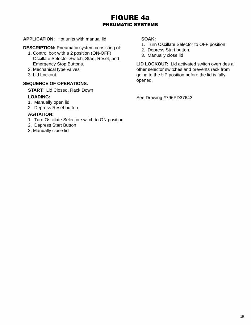
APPLICATION: Hot units with manual lid
DESCRIPTION: Pneumatic system consisting of:1. Control box with a 2 position (ON-OFF)
Oscillate Selector Switch, Start, Reset, andEmergency Stop Buttons.
2. Mechanical type valves3. Lid Lockout.
SEQUENCE OF OPERATIONS:START: Lid Closed, Rack Down
LOADING:1. Manually open lid2. Depress Reset button.
AGITATION:1. Turn Oscillate Selector switch to ON position2. Depress Start Button3. Manually close lid
SOAK:1. Turn Oscillate Selector to OFF position2. Depress Start button.3. Manually close lid
LID LOCKOUT: Lid activated switch overrides allother selector switches and prevents rack fromgoing to the UP position before the lid is fullyopened.
See Drawing #796PD37643
20
FIGURE 4bPNEUMATIC SYSTEMS
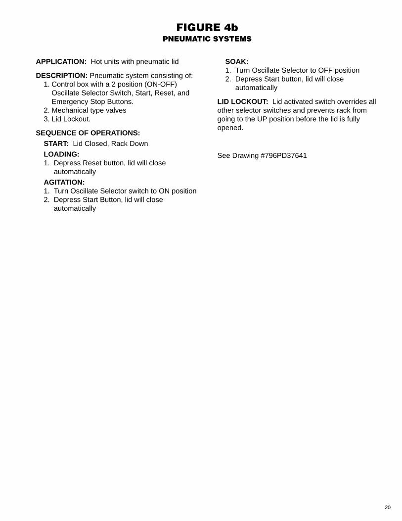
APPLICATION: Hot units with pneumatic lid
DESCRIPTION: Pneumatic system consisting of:1. Control box with a 2 position (ON-OFF)
Oscillate Selector Switch, Start, Reset, andEmergency Stop Buttons.
2. Mechanical type valves3. Lid Lockout.
SEQUENCE OF OPERATIONS:START: Lid Closed, Rack Down
LOADING:1. Depress Reset button, lid will close
automatically
AGITATION:1. Turn Oscillate Selector switch to ON position2. Depress Start Button, lid will close
automatically
SOAK:1. Turn Oscillate Selector to OFF position2. Depress Start button, lid will close
automatically
LID LOCKOUT: Lid activated switch overrides allother selector switches and prevents rack fromgoing to the UP position before the lid is fullyopened.
See Drawing #796PD37641

21
FIGURE 4cPNEUMATIC SYSTEMS
APPLICATION: Cold units with pneumatic lid
DESCRIPTION: Pneumatic system consisting of:1. Control box with a 2 position (ON-OFF)
Oscillate Selector Switch, Start, Reset, andEmergency Stop Buttons
2. Mechanical type valves3. Lid Lockout4. Fire Safety Circuit 5. Pneumatic Lid (required)
SEQUENCE OF OPERATIONS:START: Lid Closed, Rack Down
LOADING:1. Depress Reset button, lid will close
automatically
AGITATION:1. Turn Oscillate Selector switch to ON position2. Depress Start Button, lid will close
automatically
SOAK:1. Turn Oscillate Selector to OFF position2. Depress Start button, lid will close
automatically
LID LOCKOUT: Lid activated switch overrides allother selector switches and prevents rack fromgoing to the UP position before the lid is fullyopened.
FIRE SAFETY CIRCUIT: Automatically lowersrack to the bottom of the tank and closes lid in theevent of a fire inside the tank and overrides theselector switches and intermediate stop. Thesafety circuit is activated by a Graymills fusiblevent tube which, when it melts, vents amomentary air signal.
See Drawing #796PD37672
22
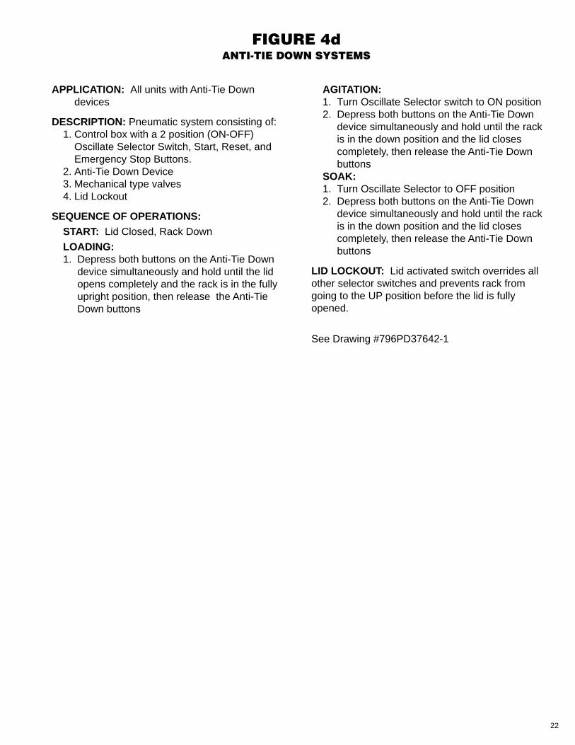
FIGURE 4dANTI-TIE DOWN SYSTEMS
APPLICATION: All units with Anti-Tie Downdevices
DESCRIPTION: Pneumatic system consisting of:1. Control box with a 2 position (ON-OFF)
Oscillate Selector Switch, Start, Reset, andEmergency Stop Buttons.
2. Anti-Tie Down Device3. Mechanical type valves4. Lid Lockout
SEQUENCE OF OPERATIONS:START: Lid Closed, Rack Down
LOADING:1. Depress both buttons on the Anti-Tie Down
device simultaneously and hold until the lidopens completely and the rack is in the fullyupright position, then release the Anti-TieDown buttons
AGITATION:1. Turn Oscillate Selector switch to ON position2. Depress both buttons on the Anti-Tie Down
device simultaneously and hold until the rackis in the down position and the lid closescompletely, then release the Anti-Tie Downbuttons
SOAK:1. Turn Oscillate Selector to OFF position2. Depress both buttons on the Anti-Tie Down
device simultaneously and hold until the rackis in the down position and the lid closescompletely, then release the Anti-Tie Downbuttons
LID LOCKOUT: Lid activated switch overrides allother selector switches and prevents rack fromgoing to the UP position before the lid is fullyopened.
See Drawing #796PD37642-1
23
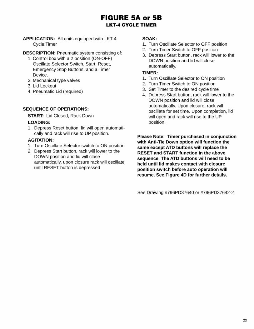
FIGURE 5A or 5BLKT-4 CYCLE TIMER
APPLICATION: All units equipped with LKT-4Cycle Timer
DESCRIPTION: Pneumatic system consisting of:1. Control box with a 2 position (ON-OFF)
Oscillate Selector Switch, Start, Reset,Emergency Stop Buttons, and a TimerDevice.
2. Mechanical type valves3. Lid Lockout4. Pneumatic Lid (required)
SEQUENCE OF OPERATIONS:START: Lid Closed, Rack Down
LOADING:1. Depress Reset button, lid will open automati-
cally and rack will rise to UP position.
AGITATION:1. Turn Oscillate Selector switch to ON position2. Depress Start button, rack will lower to the
DOWN position and lid will closeautomatically, upon closure rack will oscillateuntil RESET button is depressed
SOAK:1. Turn Oscillate Selector to OFF position2. Turn Timer Switch to OFF position3. Depress Start button, rack will lower to the
DOWN position and lid will closeautomatically.
TIMER:1. Turn Oscillate Selector to ON position2. Turn Timer Switch to ON position3. Set Timer to the desired cycle time4. Depress Start button, rack will lower to the
DOWN position and lid will closeautomatically. Upon closure, rack willoscillate for set time. Upon completion, lidwill open and rack will rise to the UPposition.
Please Note: Timer purchased in conjunctionwith Anti-Tie Down option will function thesame except ATD buttons will replace theRESET and START function in the abovesequence. The ATD buttons will need to beheld until lid makes contact with closureposition switch before auto operation willresume. See Figure 4D for further details.
See Drawing #796PD37640 or #796PD37642-2
24
FIGURE 6MANUALLY OPENED SPRING
COUNTERBALANCED COVER – STYLE #1
25
FIGURE 7CYLINDER OPERATED
COVER OPENING – STYLE #2
26
FIGURE 8VALVE CONNECTIONS
4" CYLINDER
ManifoldValve
SpeedControl
"OR"Valve
3-WayPressure
PilotValve
Turbo Boost Filtration Connection
Cover Assembly
3-Way Valve
Right Side ofTank Assembly
PressurePilot Valve
Limit Valve
ImpulseRelay Valve
SpeedControl Valve
Pilot OperatedCheck
Fill PortTurbo Boost Filtration ConnectionReturn Port/Overflow Port
Turbo Boost Filtration Connection
Cover Assembly
Right Side ofTank Assembly
3-Way Valve
ManifoldValve
ImpulseRelayValve
SpeedControl
"OR"Valve
3-WayPressure
PilotValve
Pilot OperatedCheck
SpeedControl Valve
Limit Valve
PressurePilot Valve
Fill PortTurbo Boost Filtration ConnectionReturn Port/Overflow Port
5" CYLINDER
27
FIGURE 9a FIGURE 9b
FLOOR MOUNTING HOLE LOCATIONS
TEMPERATURECONTROL DIAL780-06079
LIFTKLEEN OPERATING SWITCH FORAGITATED PLATFORM MODELS & TEMPERATURE ADJUSTMENT
PNEUMATIC LID – STYLE #2 DIAL
FIGURE 10 FIGURE 11
28
HEAT UP TIME (HOURS)
TAN
K T
EM
PE
RA
TU
RE
(F
°)
(1) LKR 36
(2) LKR 60 (3 Heaters)
(3) LKR 48
(4) LKD 60 (3 Heaters)
(5) LKR 60 (2 Heaters)
(6) LKD 60 (2 Heaters)
FIGURE 12HEATUP TIME
29
FIGURE 13
Speed ControlAdjustmentfor the Lid
Speed ControlAdjustment
for the Rack
Speed ControlAdjustmentfor the Lid
Speed ControlAdjustment
for the Rack
Speed ControlAdjustmentfor the Lid
Speed ControlAdjustment
for the Rack
4" CYLINDER 5" CYLINDER 5" DUAL CYLINDER
SPEED CONTROLS
FILTER
REGULATOR
MASTERON/OFFVALVE
LUBRICATOR
AIR LINE TO UNIT
MASTER “ON/OFF” VALVE AND RECOMMENDED AIR LINE CONNECTIONAIR FILTER/REGULATOR/LUBRICATOR TO ALL LIFTKLEEN MODELS
FIGURE 14 FIGURE 15
30
SUPERFLO PUMP DISCHARGE NOZZLE
FIGURE 16
FIGURE 17
Note: For Teflon coated pumps and steam heated pumps consult factory.
PUMP ASSEMBLY
31
FIGURE 18
LIFTING MECHANISM & LID ASSEMBLYLUBRICATION POINT
STEAM HEATING ARRANGEMENT
FIGURE 19
32
FIGURE 20
FIGURE 21
—NOTE—1. PLUMBING CONNECTIONS ARE
MADE AS FOLLOWS:STRAINERS AND DISPOSABLE BAG ELEMENTSFLOW FROM INSIDE-OUT (CENTER PORT IS THE INLET)STACKED DISC ELEMENTS FLOW FROMOUTSIDE-IN (CENTER PORT IS THE OUTLET)
NOTE:APPLY PIPE DOPE TO ALLCONNECTIONS
MODEL LKF-100 FILTRATION SYSTEM
MODEL LKF-22 FILTRATION SYSTEM
—NOTE—1. PLUMBING CONNECTIONS ARE
MADE AS FOLLOWS:STRAINERS AND DISPOSABLE BAG ELEMENTSFLOW FROM INSIDE-OUT (CENTER PORT IS THE INLET)STACKED DISC ELEMENTS FLOW FROMOUTSIDE-IN (CENTER PORT IS THE OUTLET)
NOTE:APPLY PIPE DOPE TO ALLCONNECTIONS
33
PNEUMATIC TUBING CONNECTION/DISCONNECT PROCEDURE
FIGURE 22