partition of the circle in cells of equal area and shape - … of the circle in cells of equal area...
TRANSCRIPT
Partition of the circle in cells of equal area and shape
Luc Masset∗, Olivier Bruls and Gaetan Kerschen∗Structural Dynamics Research Group
Aerospace and Mechanical Engineering DepartmentUniversity of Liege
Institut de Mecanique et Genie Civil (B52/3), 1 chemin des chevreuils4000 Liege, Belgium
email: [email protected]: www.ltas-vis.ulg.ac.be
Abstract
In the present paper, a new method for partitioning acircle in cells is presented. Cells have equal areas andshapes, so the method is termed the Isocell method. Itsmost interesting property is that cell centres are uni-formly distributed inside the circle. Among possibleapplications of the Isocell method, the calculation ofview factors by ray-tracing (image rendering, radiativeheat transfer modelling) is presented.
Keywords: circle partition, cells, ray-tracing, viewfactor, rendering, projection
1 Introduction
Partition of common geometrical shapes and surfaceshas always been a major concern in many differ-ent fields such as geography, cartography, computergraphics or scientific visualisation. Partition is oftenlinked with tessellation, subdivision or tiling methods.Even though the purposes of these methods are dif-ferent, the principle remains the same: decompose acomplex surface in basic elements, usually trianglesor quadrangles.
In the field of Digital Terrain Models, Bjørke et al.[?] develop a global grid model based on quadrilateralcells of almost constant area. They apply their modelto the case of a space corpse with an ellipsoid shape.Chukkapalli et al. [?] present a scheme to generate un-structured grids on the sphere. Their method is basedon a spiral going from one pole to the other. Stuhneand Peltier [?] study the shallow water equations onthe sphere using an icosahedral grid-point discretisa-
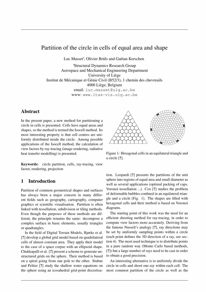
Figure 1: Hexagonal cells in an equilateral triangle anda circle [?].
tion. Leopardi [?] presents the partitions of the unitsphere into regions of equal area and small diameter aswell as several applications (optimal packing of caps,Voronoi tessellation ...). Cox [?] studies the problemof deformable bubbles confined in an equilateral trian-gle and a circle (Fig. 1). The shapes are filled withhexagonal cells and their method is based on Voronoidiagrams.
The starting point of this work was the need for anefficient shooting method for ray-tracing, in order tocompute view factors more accurately. Deriving fromthe famous Nusselt’s analogy [?], ray directions maybe set by uniformly sampling points within a circle(each point defines the 3D direction of a ray, see sec-tion 4). The most used technique is to distribute pointsin a pure random way (Monte Carlo based methods,[?]) but a large number of rays need to be cast in orderto obtain a good precision.
An interesting alternative is to uniformly divide thecircle in cells and shoot one ray within each cell. Themost common partition of the circle as well as the
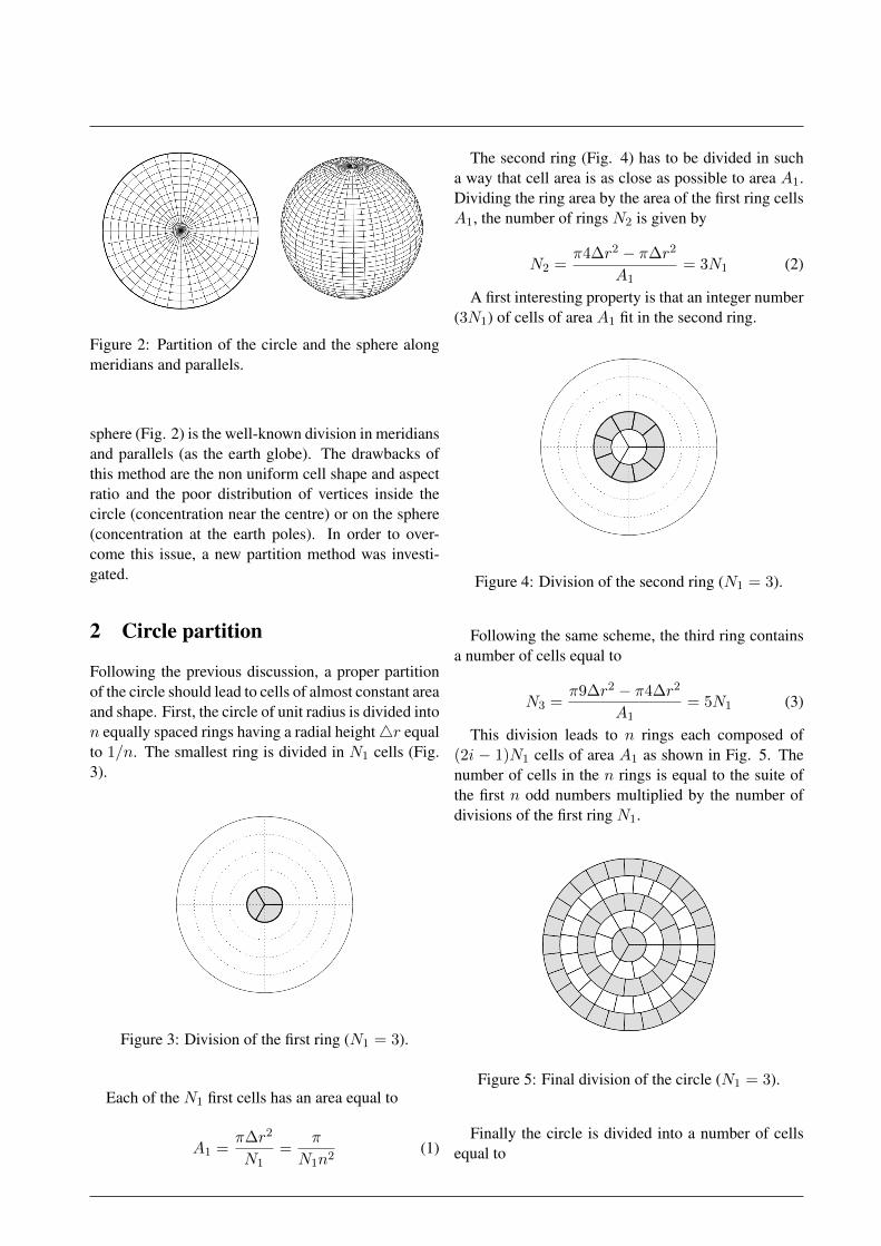
Figure 2: Partition of the circle and the sphere alongmeridians and parallels.
sphere (Fig. 2) is the well-known division in meridiansand parallels (as the earth globe). The drawbacks ofthis method are the non uniform cell shape and aspectratio and the poor distribution of vertices inside thecircle (concentration near the centre) or on the sphere(concentration at the earth poles). In order to over-come this issue, a new partition method was investi-gated.
2 Circle partition
Following the previous discussion, a proper partitionof the circle should lead to cells of almost constant areaand shape. First, the circle of unit radius is divided inton equally spaced rings having a radial height4r equalto 1/n. The smallest ring is divided in N1 cells (Fig.3).
Figure 3: Division of the first ring (N1 = 3).
Each of the N1 first cells has an area equal to
A1 =π∆r2
N1=
π
N1n2(1)
The second ring (Fig. 4) has to be divided in sucha way that cell area is as close as possible to area A1.Dividing the ring area by the area of the first ring cellsA1, the number of rings N2 is given by
N2 =π4∆r2 − π∆r2
A1= 3N1 (2)
A first interesting property is that an integer number(3N1) of cells of area A1 fit in the second ring.
Figure 4: Division of the second ring (N1 = 3).
Following the same scheme, the third ring containsa number of cells equal to
N3 =π9∆r2 − π4∆r2
A1= 5N1 (3)
This division leads to n rings each composed of(2i − 1)N1 cells of area A1 as shown in Fig. 5. Thenumber of cells in the n rings is equal to the suite ofthe first n odd numbers multiplied by the number ofdivisions of the first ring N1.
Figure 5: Final division of the circle (N1 = 3).
Finally the circle is divided into a number of cellsequal to
Ntot = N1
n∑i=1
(2i− 1) = N1n2 (4)
Fig. 6 shows the partitions obtained with differentnumbers of initial divisions (N1) and different totalnumbers of cells.
Figure 6: Circle partition with N1 = 5 and 125 cells(a), N1 = 4 and 256 cells (b) and N1 = 3 and 507cells (c).
Provided a required number of cellsNtarget, the realnumber of rings n∗ is given by
n∗ =
√Ntarget
N1(5)
and the actual number of rings n is the integer valuestrictly greater than n∗. Then the total number of cellsis given by Eq. 4.
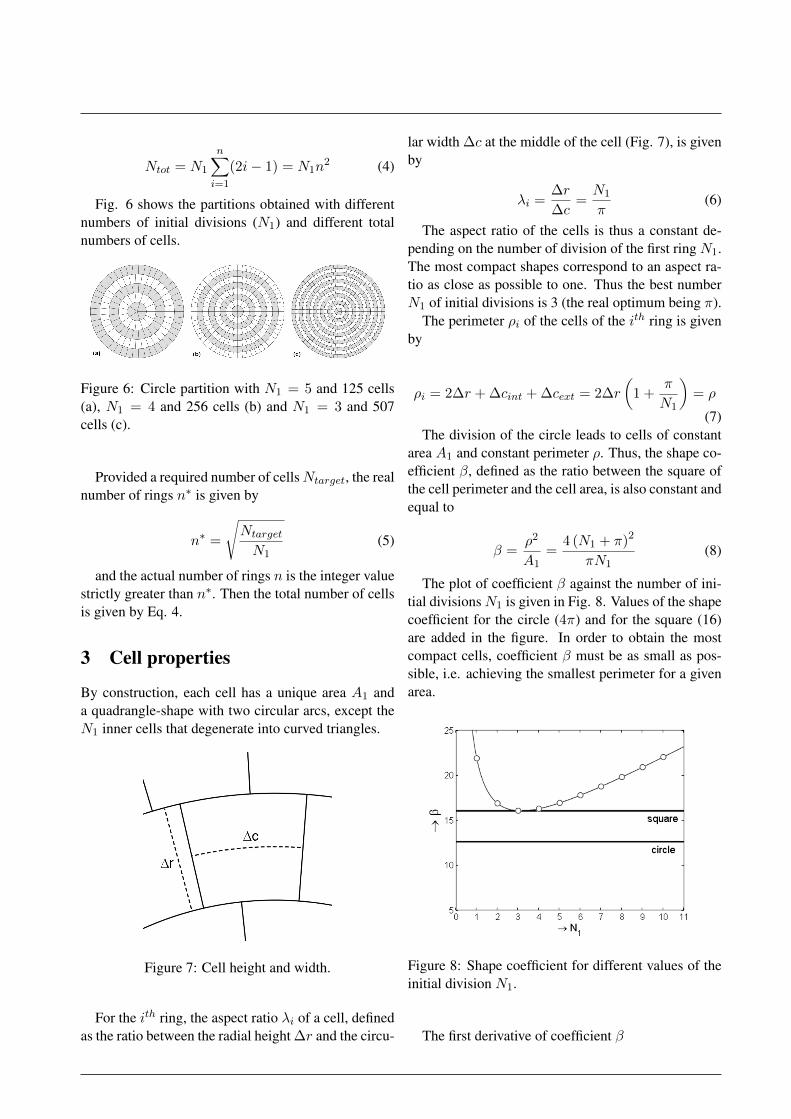
3 Cell properties
By construction, each cell has a unique area A1 anda quadrangle-shape with two circular arcs, except theN1 inner cells that degenerate into curved triangles.
Figure 7: Cell height and width.
For the ith ring, the aspect ratio λi of a cell, definedas the ratio between the radial height ∆r and the circu-
lar width ∆c at the middle of the cell (Fig. 7), is givenby
λi =∆r
∆c=N1
π(6)
The aspect ratio of the cells is thus a constant de-pending on the number of division of the first ring N1.The most compact shapes correspond to an aspect ra-tio as close as possible to one. Thus the best numberN1 of initial divisions is 3 (the real optimum being π).
The perimeter ρi of the cells of the ith ring is givenby
ρi = 2∆r + ∆cint + ∆cext = 2∆r
(1 +
π
N1
)= ρ
(7)The division of the circle leads to cells of constant
area A1 and constant perimeter ρ. Thus, the shape co-efficient β, defined as the ratio between the square ofthe cell perimeter and the cell area, is also constant andequal to
β =ρ2
A1=
4 (N1 + π)2
πN1(8)
The plot of coefficient β against the number of ini-tial divisionsN1 is given in Fig. 8. Values of the shapecoefficient for the circle (4π) and for the square (16)are added in the figure. In order to obtain the mostcompact cells, coefficient β must be as small as pos-sible, i.e. achieving the smallest perimeter for a givenarea.
Figure 8: Shape coefficient for different values of theinitial division N1.
The first derivative of coefficient β
dβ
dN1=
4
π
N21 − π2
N21
(9)
is equal to zero when N1 is equal to π while its sec-ond derivative,
d2β
dN21
=8π
N31
(10)
is always positive. Thus the optimal value of N1 isπ for which the shape coefficient β is equal to 16. Theinteger closest to π is 3, for which cells are almost asgood as squares (β = 16.0085).
4 Ray-tracing
Figure 9: A ray emitted by facet i and reaching facetj.
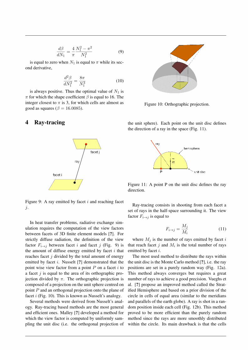
In heat transfer problems, radiative exchange sim-ulation requires the computation of the view factorsbetween facets of 3D finite element models [?]. Forstrictly diffuse radiation, the definition of the viewfactor Fi→j between facet i and facet j (Fig. 9) isthe amount of diffuse energy emitted by facet i thatreaches facet j divided by the total amount of energyemitted by facet i. Nusselt [?] demonstrated that thepoint wise view factor from a point P on a facet i toa facet j is equal to the area of its orthographic pro-jection divided by π. The orthographic projection iscomposed of a projection on the unit sphere centred onpoint P and an orthogonal projection onto the plane offacet i (Fig. 10). This is known as Nusselt’s analogy.
Several methods were derived from Nusselt’s anal-ogy. Ray-tracing based methods are the most generaland efficient ones. Malley [?] developed a method forwhich the view factor is computed by uniformly sam-pling the unit disc (i.e. the orthogonal projection of
Figure 10: Orthographic projection.
the unit sphere). Each point on the unit disc definesthe direction of a ray in the space (Fig. 11).
Figure 11: A point P on the unit disc defines the raydirection.
Ray-tracing consists in shooting from each facet aset of rays in the half-space surrounding it. The viewfactor Fi→j is equal to
Fi→j =Mj
Mi(11)
where Mj is the number of rays emitted by facet ithat reach facet j and Mi is the total number of raysemitted by facet i.
The most used method to distribute the rays withinthe unit disc is the Monte Carlo method [?], i.e. the raypositions are set in a purely random way (Fig. 12a).This method always converges but requires a greatnumber of rays to achieve a good precision. Vueghs etal. [?] propose an improved method called the Strat-ified Hemisphere and based on a prior division of thecircle in cells of equal area (similar to the meridiansand parallels of the earth globe). A ray is shot in a ran-dom position inside each cell (Fig. 12b). This methodproved to be more efficient than the purely randommethod since the rays are more smoothly distributedwithin the circle. Its main drawback is that the cells
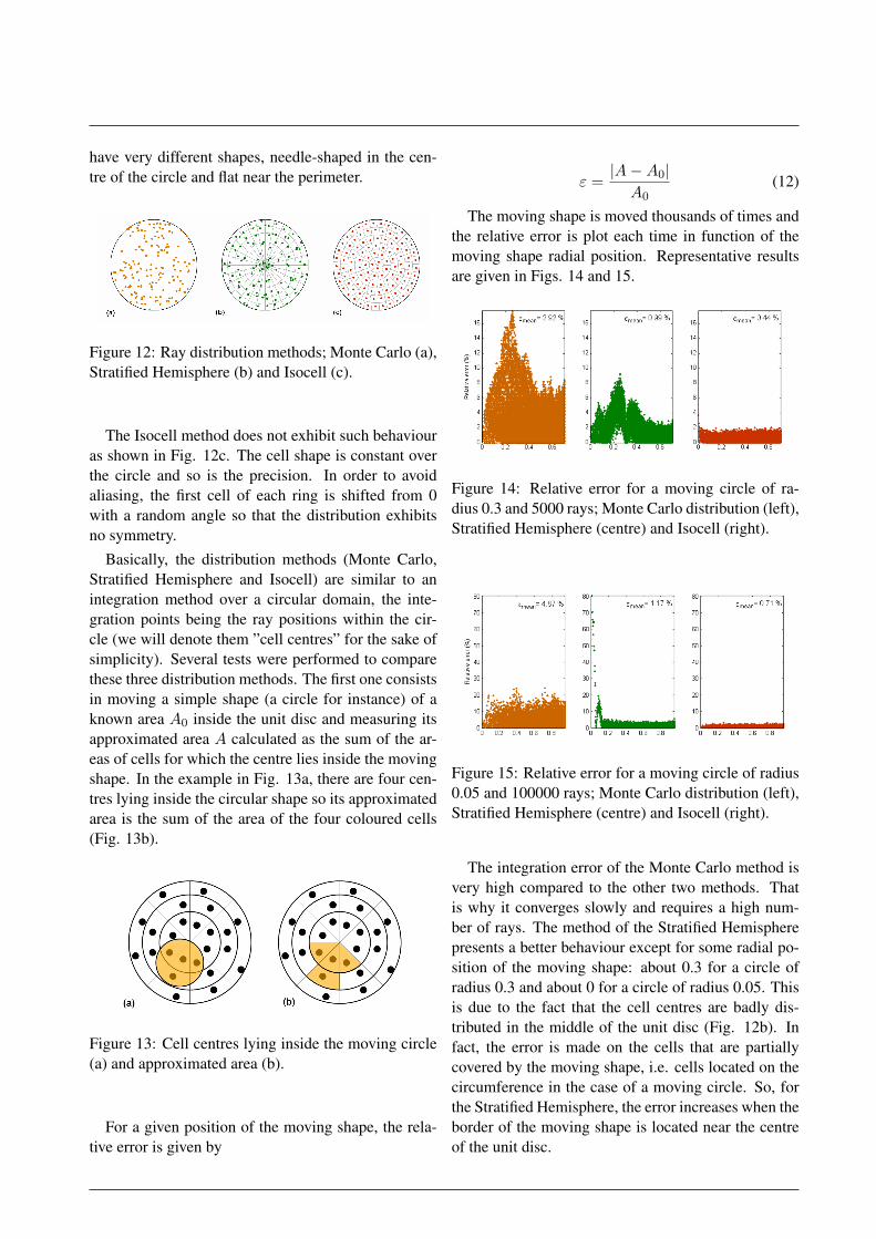
have very different shapes, needle-shaped in the cen-tre of the circle and flat near the perimeter.
Figure 12: Ray distribution methods; Monte Carlo (a),Stratified Hemisphere (b) and Isocell (c).
The Isocell method does not exhibit such behaviouras shown in Fig. 12c. The cell shape is constant overthe circle and so is the precision. In order to avoidaliasing, the first cell of each ring is shifted from 0with a random angle so that the distribution exhibitsno symmetry.
Basically, the distribution methods (Monte Carlo,Stratified Hemisphere and Isocell) are similar to anintegration method over a circular domain, the inte-gration points being the ray positions within the cir-cle (we will denote them ”cell centres” for the sake ofsimplicity). Several tests were performed to comparethese three distribution methods. The first one consistsin moving a simple shape (a circle for instance) of aknown area A0 inside the unit disc and measuring itsapproximated area A calculated as the sum of the ar-eas of cells for which the centre lies inside the movingshape. In the example in Fig. 13a, there are four cen-tres lying inside the circular shape so its approximatedarea is the sum of the area of the four coloured cells(Fig. 13b).
Figure 13: Cell centres lying inside the moving circle(a) and approximated area (b).
For a given position of the moving shape, the rela-tive error is given by
ε =|A−A0|A0
(12)
The moving shape is moved thousands of times andthe relative error is plot each time in function of themoving shape radial position. Representative resultsare given in Figs. 14 and 15.
Figure 14: Relative error for a moving circle of ra-dius 0.3 and 5000 rays; Monte Carlo distribution (left),Stratified Hemisphere (centre) and Isocell (right).
Figure 15: Relative error for a moving circle of radius0.05 and 100000 rays; Monte Carlo distribution (left),Stratified Hemisphere (centre) and Isocell (right).
The integration error of the Monte Carlo method isvery high compared to the other two methods. Thatis why it converges slowly and requires a high num-ber of rays. The method of the Stratified Hemispherepresents a better behaviour except for some radial po-sition of the moving shape: about 0.3 for a circle ofradius 0.3 and about 0 for a circle of radius 0.05. Thisis due to the fact that the cell centres are badly dis-tributed in the middle of the unit disc (Fig. 12b). Infact, the error is made on the cells that are partiallycovered by the moving shape, i.e. cells located on thecircumference in the case of a moving circle. So, forthe Stratified Hemisphere, the error increases when theborder of the moving shape is located near the centreof the unit disc.
Unlike the stratified hemisphere method, the Isocellmethod performs equally for any radial position of themoving shape. Compared to Monte Carlo based meth-ods, the Isocell method achieves a precision about 10times greater for a given number of rays. Put it anotherway, it is possible to shoot 10 times less rays with theIsocell method to achieve the same precision. This isvery useful since ray-tracing methods are known to behighly time consuming.
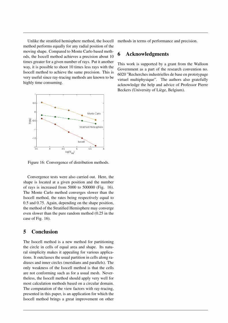
Figure 16: Convergence of distribution methods.
Convergence tests were also carried out. Here, theshape is located at a given position and the numberof rays is increased from 5000 to 500000 (Fig. 16).The Monte Carlo method converges slower than theIsocell method, the rates being respectively equal to0.5 and 0.75. Again, depending on the shape position,the method of the Stratified Hemisphere may convergeeven slower than the pure random method (0.25 in thecase of Fig. 16).
5 Conclusion
The Isocell method is a new method for partitioningthe circle in cells of equal area and shape. Its natu-ral simplicity makes it appealing for various applica-tions. It outclasses the usual partition in cells along ra-diuses and inner circles (meridians and parallels). Theonly weakness of the Isocell method is that the cellsare not conforming such as for a usual mesh. Never-theless, the Isocell method should apply very well formost calculation methods based on a circular domain.The computation of the view factors with ray-tracing,presented in this paper, is an application for which theIsocell method brings a great improvement on other
methods in terms of performance and precision.
6 Acknowledgments
This work is supported by a grant from the WalloonGovernment as a part of the research convention no.6020 ”Recherches industrielles de base en prototypagevirtuel multiphysique”. The authors also gratefullyacknowledge the help and advice of Professor PierreBeckers (University of Liege, Belgium).