particle detectors - florida state universitywahl/quarknet/summer2001/detectors.pdfdetectors...
TRANSCRIPT
Particle Detectors(Horst Wahl, Quarknet lecture, June 2001)
particle physics experiments – introduction interactions of particles with matter detectors triggers D0 detector CMS detector
Webpages of interest ! http://www.fnal.gov (Fermilab homepage)! http://www.hep.fsu.edu/~wahl/Quarknet (has links to
many particle physics sites)! http://www.fnal.gov/pub/tour.html (Fermilab particle
physics tour)! http://ParticleAdventure.org/ (Lawrence Berkeley
Lab.)! http://www.cern.ch (CERN -- European Laboratory
for Particle Physics)
Outline:
Particle physics experiments
Particle physics experiments:! collide particles to
" produce new particles " reveal their internal structure and laws of
their interactions by observing regularities, measuring cross sections,...
! colliding particles need to have high energy " to make objects of large mass " to resolve structure at small distances
! to study structure of small objects:" need probe with short wavelength: use
particles with high momentum to get short wavelength
" remember de Broglie wavelength of a particle λλλλ = h/p
! in particle physics, mass-energy equivalence plays an important role; in collisions, kinetic energy converted into mass energy;
" relation between kinetic energy K, total energy E and momentum p :
E = K + mc2 = √√√√(pc)2 + (mc2)c2___________
How to do a particle physics experiment
Outline of experiment:! get particles (e.g. protons, antiprotons,…)! accelerate them! throw them against each other! observe and record what happens! analyse and interpret the data
ingredients needed:! particle source! accelerator and aiming device! detector! trigger (decide what to record)! recording device! many people to:
" design, build, test, operate accelerator " design, build, test, calibrate, operate, and
understand detector" analyze data
! lots of money to pay for all of this
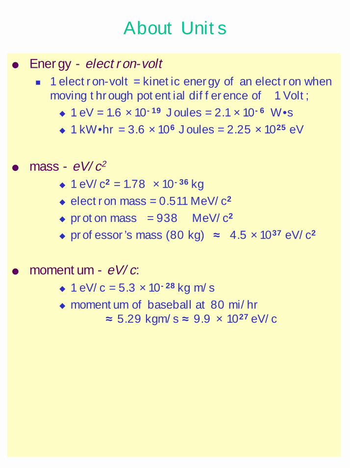
About Units
Energy - electron-volt! 1 electron-volt = kinetic energy of an electron when
moving through potential difference of 1 Volt;" 1 eV = 1.6 × 10⁻¹⁹ Joules = 2.1 × 10⁻⁶ W•s" 1 kW•hr = 3.6 × 10⁶ Joules = 2.25 × 1025 eV
mass - eV/c2
" 1 eV/c2 = 1.78 × 10-36 kg" electron mass = 0.511 MeV/c2
" proton mass = 938 MeV/c2
" professor’s mass (80 kg) ≈≈≈≈ 4.5 × 1037 eV/c2
momentum - eV/c: " 1 eV/c = 5.3 × 10⁻²⁸ kg m/s" momentum of baseball at 80 mi/hr
≈≈≈≈ 5.29 kgm/s ≈≈≈≈ 9.9 × 1027 eV/c
WHY CAN'T WE SEE ATOMS?
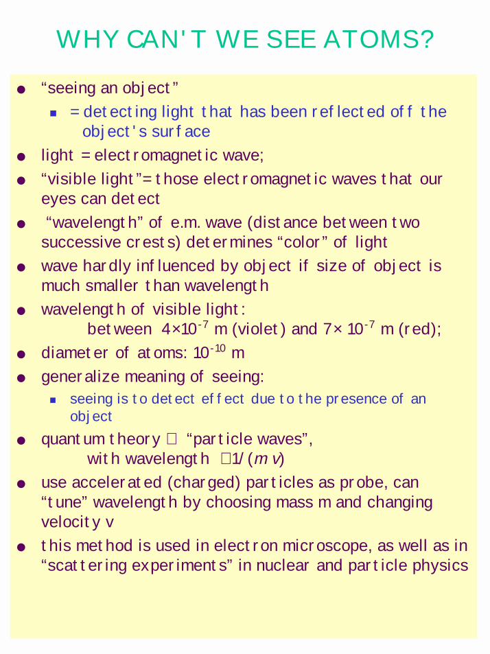
“seeing an object”! = detecting light that has been reflected off the
object's surface light = electromagnetic wave; “visible light”= those electromagnetic waves that our
eyes can detect “wavelength” of e.m. wave (distance between two
successive crests) determines “color” of light wave hardly influenced by object if size of object is
much smaller than wavelength wavelength of visible light:
between 4×10⁻⁷ m (violet) and 7× 10⁻⁷ m (red); diameter of atoms: 10-10 m generalize meaning of seeing:
! seeing is to detect effect due to the presence of an object
quantum theory ⇒ “particle waves”,with wavelength ∝ 1/(m v)
use accelerated (charged) particles as probe, can “tune” wavelength by choosing mass m and changing velocity v
this method is used in electron microscope, as well as in “scattering experiments” in nuclear and particle physics
Detectors Detectors
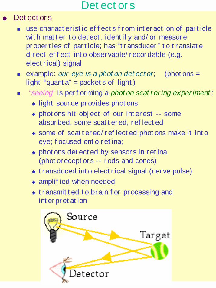
! use characteristic effects from interaction of particle with matter to detect, identify and/or measure properties of particle; has “transducer” to translate direct effect into observable/recordable (e.g. electrical) signal
! example: our eye is a photon detector; (photons = light “quanta” = packets of light)
! “seeing” is performing a photon scattering experiment:" light source provides photons" photons hit object of our interest -- some
absorbed, some scattered, reflected" some of scattered/reflected photons make it into
eye; focused onto retina;" photons detected by sensors in retina
(photoreceptors -- rods and cones) " transduced into electrical signal (nerve pulse)" amplified when needed" transmitted to brain for processing and
interpretation
Particle interactions with matter
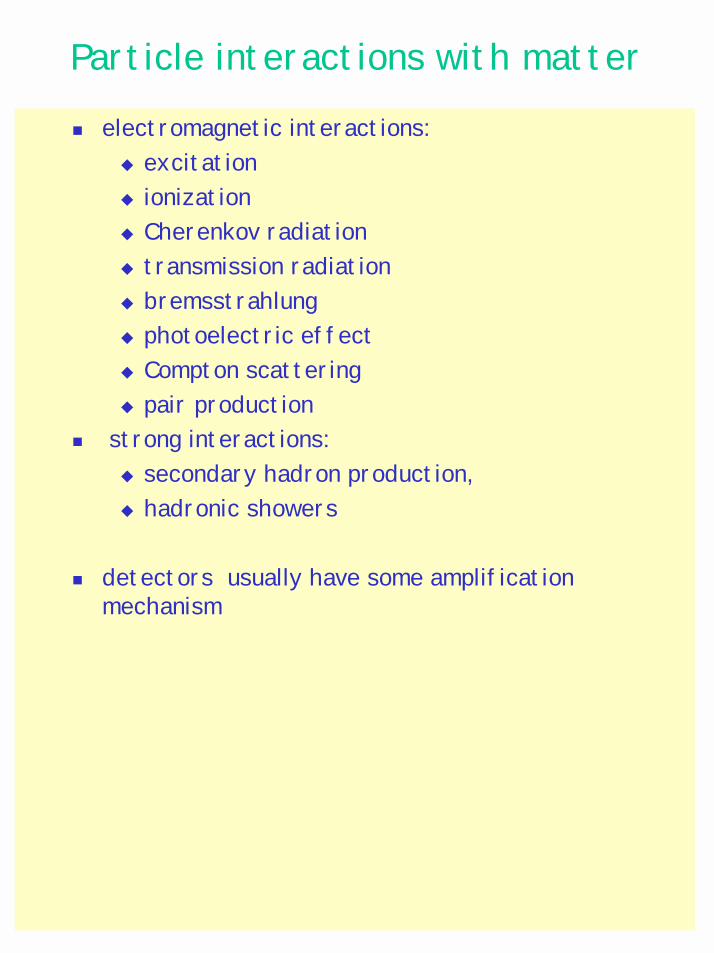
! electromagnetic interactions: " excitation" ionization" Cherenkov radiation" transmission radiation" bremsstrahlung " photoelectric effect" Compton scattering" pair production
! strong interactions:" secondary hadron production, " hadronic showers
! detectors usually have some amplification mechanism
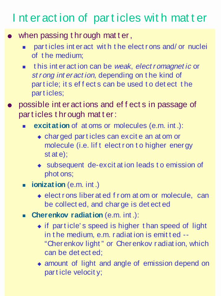
Interaction of particles with matter when passing through matter,
! particles interact with the electrons and/or nuclei of the medium;
! this interaction can be weak, electromagnetic or strong interaction, depending on the kind of particle; its effects can be used to detect the particles;
possible interactions and effects in passage of particles through matter: ! excitation of atoms or molecules (e.m. int.):
" charged particles can excite an atom or molecule (i.e. lift electron to higher energy state);
" subsequent de-excitation leads to emission of photons;
! ionization (e.m. int.) " electrons liberated from atom or molecule, can
be collected, and charge is detected ! Cherenkov radiation (e.m. int.):
" if particle's speed is higher than speed of light in the medium, e.m. radiation is emitted --“Cherenkov light” or Cherenkov radiation, which can be detected;
" amount of light and angle of emission depend on particle velocity;
Interaction of particles with matter, cont’d
! transition radiation (e.m. int.): " when a charged particle crosses the boundary
between two media with different speeds of light (different “refractive index”), e.m. radiation is emitted -- “transition radiation”
" amount of radiation grows with (energy/mass); ! bremsstrahlung (= braking radiation) (e.m. int.):
" when charged particle's velocity changes, e.m. radiation is emitted;
" due to interaction with nuclei, particles deflected and slowed down emit bremsstrahlung;
" effect stronger, the bigger (energy/mass) ⇒⇒⇒⇒electrons with high energy most strongly affected;
! pair production (e.m. int.):" by interaction with e.m. field of nucleus, photons
can convert into electron-positron pairs ! electromagnetic shower (e.m. int.):
" high energy electrons and photons can cause “electromagnetic shower” by successivebremsstrahlung and pair production
! hadron production (strong int.): " strongly interacting particles can produce new
particles by strong interaction, which in turn can produce particles,... “hadronic shower”
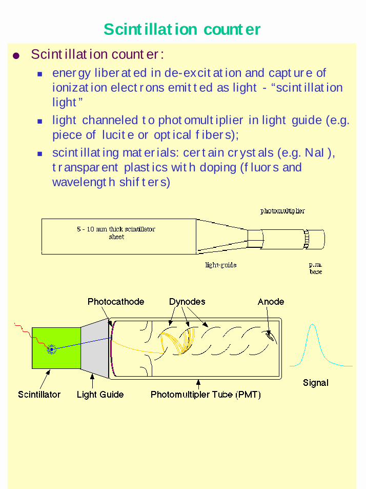
Scintillation counter Scintillation counter:
! energy liberated in de-excitation and capture of ionization electrons emitted as light - “scintillation light”
! light channeled to photomultiplier in light guide (e.g. piece of lucite or optical fibers);
! scintillating materials: certain crystals (e.g. NaI), transparent plastics with doping (fluors and wavelength shifters)
Photomultiplier
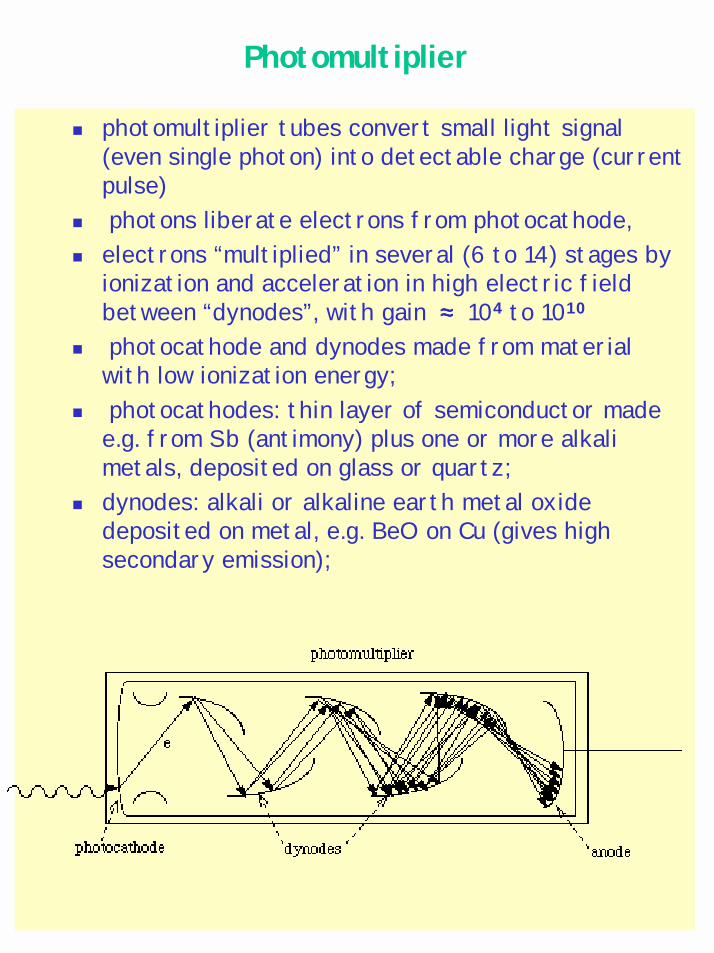
! photomultiplier tubes convert small light signal (even single photon) into detectable charge (current pulse)
! photons liberate electrons from photocathode, ! electrons “multiplied” in several (6 to 14) stages by
ionization and acceleration in high electric field between “dynodes”, with gain ≈≈≈≈ 104 to 1010
! photocathode and dynodes made from material with low ionization energy;
! photocathodes: thin layer of semiconductor made e.g. from Sb (antimony) plus one or more alkali metals, deposited on glass or quartz;
! dynodes: alkali or alkaline earth metal oxide deposited on metal, e.g. BeO on Cu (gives high secondary emission);
Spark chamber
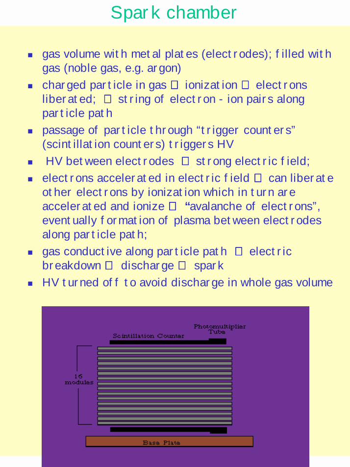
! gas volume with metal plates (electrodes); filled with gas (noble gas, e.g. argon)
! charged particle in gas ⇒⇒⇒⇒ ionization ⇒⇒⇒⇒ electrons liberated; ⇒⇒⇒⇒ string of electron - ion pairs along particle path
! passage of particle through “trigger counters” (scintillation counters) triggers HV
! HV between electrodes ⇒⇒⇒⇒ strong electric field;! electrons accelerated in electric field ⇒⇒⇒⇒ can liberate
other electrons by ionization which in turn are accelerated and ionize ⇒⇒⇒⇒ “avalanche of electrons”, eventually formation of plasma between electrodes along particle path;
! gas conductive along particle path ⇒⇒⇒⇒ electric breakdown ⇒⇒⇒⇒ discharge ⇒⇒⇒⇒ spark
! HV turned off to avoid discharge in whole gas volume
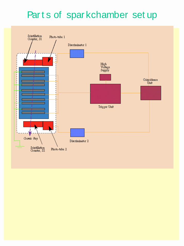
Parts of sparkchamber setup
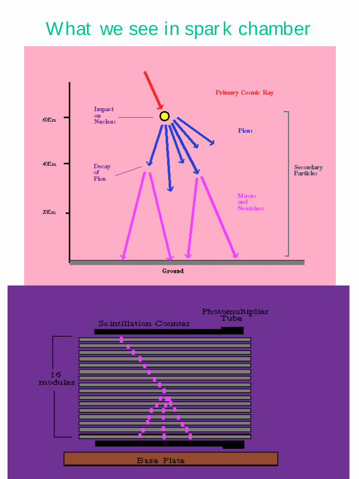
What we see in spark chamber
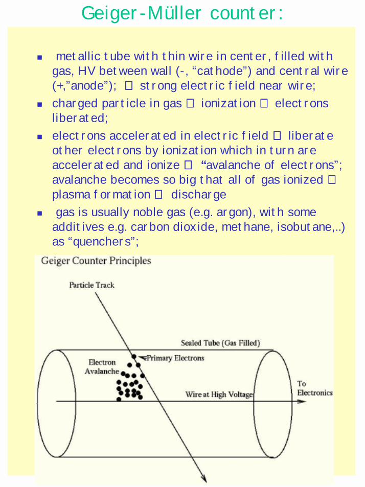
Geiger-Müller counter:
! metallic tube with thin wire in center, filled with gas, HV between wall (-, “cathode”) and central wire (+,”anode”); ⇒⇒⇒⇒ strong electric field near wire;
! charged particle in gas ⇒⇒⇒⇒ ionization ⇒⇒⇒⇒ electrons liberated;
! electrons accelerated in electric field ⇒⇒⇒⇒ liberate other electrons by ionization which in turn are accelerated and ionize ⇒⇒⇒⇒ “avalanche of electrons”; avalanche becomes so big that all of gas ionized ⇒⇒⇒⇒plasma formation ⇒⇒⇒⇒ discharge
! gas is usually noble gas (e.g. argon), with some additives e.g. carbon dioxide, methane, isobutane,..) as “quenchers”;
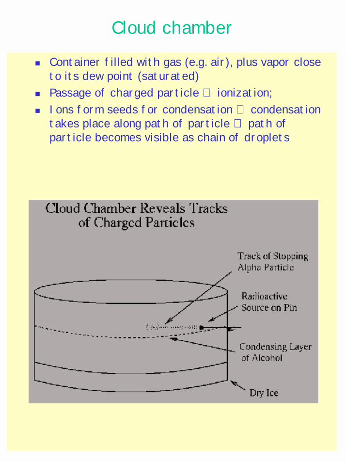
Cloud chamber
! Container filled with gas (e.g. air), plus vapor close to its dew point (saturated)
! Passage of charged particle ⇒ ionization; ! Ions form seeds for condensation ⇒ condensation
takes place along path of particle ⇒ path of particle becomes visible as chain of droplets
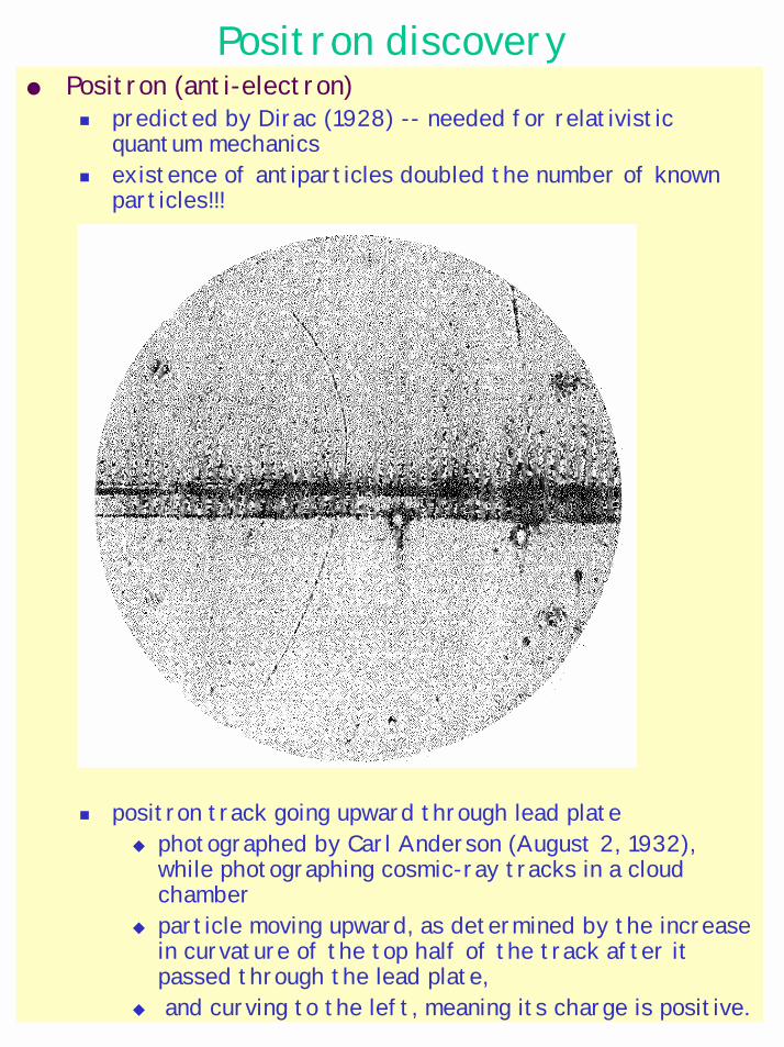
Positron discovery Positron (anti-electron)
! predicted by Dirac (1928) -- needed for relativistic quantum mechanics
! existence of antiparticles doubled the number of known particles!!!
! positron track going upward through lead plate" photographed by Carl Anderson (August 2, 1932),
while photographing cosmic-ray tracks in a cloud chamber
" particle moving upward, as determined by the increase in curvature of the top half of the track after it passed through the lead plate,
" and curving to the left, meaning its charge is positive.
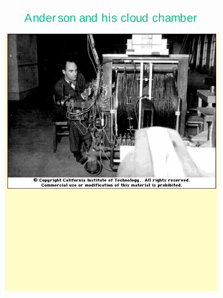
Anderson and his cloud chamber
Bubble chamber
bubble chamber! Vessel, filled (e.g.) with liquid hydrogen at a
temperature above the normal boiling point but held under a pressure of about 10 atmospheres by a large piston to prevent boiling.
! When particles have passed, and possibly interacted in the chamber, the piston is moved to reduce the pressure, allowing bubbles to develop along particle tracks.
! After about 3 milliseconds have elapsed for bubbles to grow, tracks are photographed using flash photography. Several cameras provide stereo views of the tracks.
! The piston is then moved back to recompress the liquid and collapse the bubbles before boiling can occur.
Invented by Glaser in 1952 (when he was drinking beer)
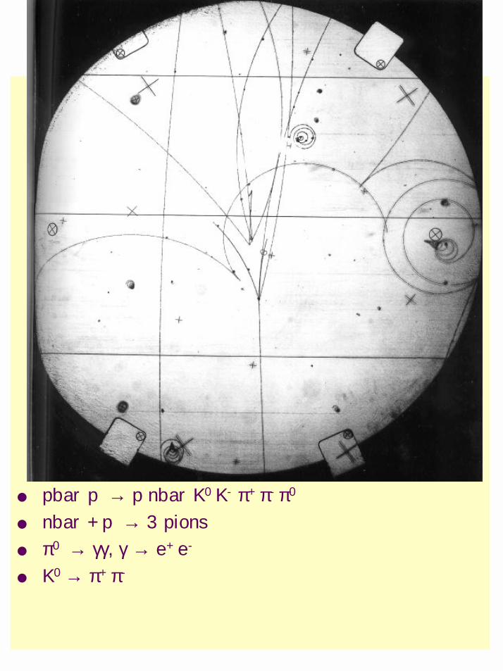
pbar p → p nbar K0 K- π+ π- π0
nbar + p → 3 pions π0 → γγ, γ → e+ e-
K0 → π+ π-
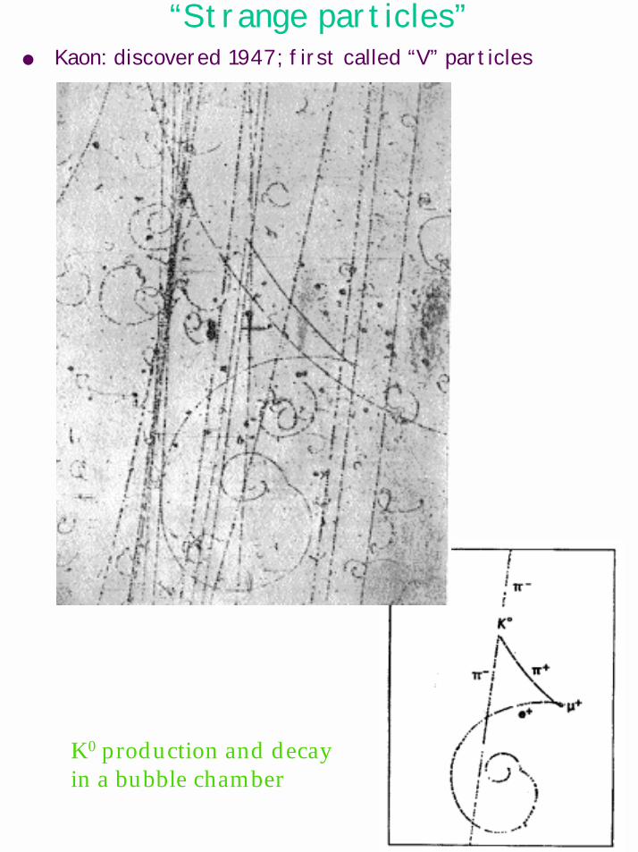
“Strange particles” Kaon: discovered 1947; first called “V” particles
K0 production and decayin a bubble chamber
Proportional tube
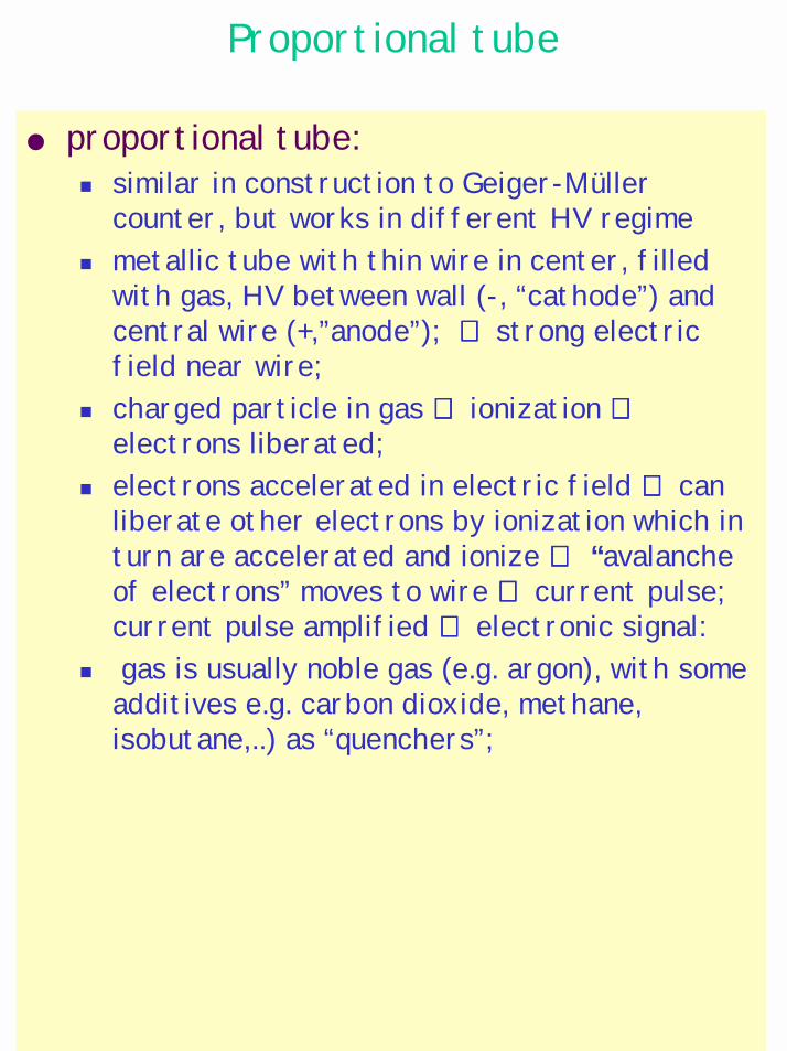
proportional tube:! similar in construction to Geiger-Müller
counter, but works in different HV regime! metallic tube with thin wire in center, filled
with gas, HV between wall (-, “cathode”) and central wire (+,”anode”); ⇒⇒⇒⇒ strong electric field near wire;
! charged particle in gas ⇒⇒⇒⇒ ionization ⇒⇒⇒⇒electrons liberated;
! electrons accelerated in electric field ⇒⇒⇒⇒ can liberate other electrons by ionization which in turn are accelerated and ionize ⇒⇒⇒⇒ “avalanche of electrons” moves to wire ⇒⇒⇒⇒ current pulse; current pulse amplified ⇒⇒⇒⇒ electronic signal:
! gas is usually noble gas (e.g. argon), with some additives e.g. carbon dioxide, methane,isobutane,..) as “quenchers”;
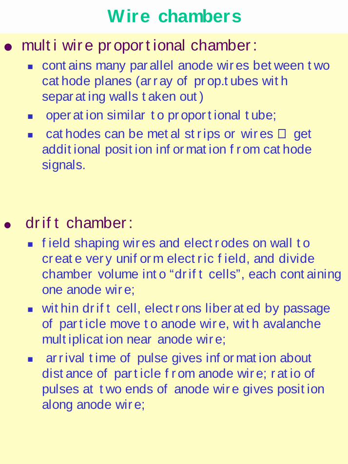
Wire chambers multi wire proportional chamber:
! contains many parallel anode wires between two cathode planes (array of prop.tubes with separating walls taken out)
! operation similar to proportional tube;! cathodes can be metal strips or wires ⇒⇒⇒⇒ get
additional position information from cathode signals.
drift chamber:! field shaping wires and electrodes on wall to
create very uniform electric field, and divide chamber volume into “drift cells”, each containing one anode wire;
! within drift cell, electrons liberated by passage of particle move to anode wire, with avalanche multiplication near anode wire;
! arrival time of pulse gives information about distance of particle from anode wire; ratio of pulses at two ends of anode wire gives position along anode wire;
Particle detectors, cont’d
Cherenkov detector:! measure Cherenkov light (amount and/or angle)
emitted by particle going through counter volume filled with transparent gas, liquid, aerogel, or solid ⇒⇒⇒⇒ get information about speed of particle.
calorimeter:! “destructive” method of measuring a particle's
energy: put enough material into particle's way to force formation of electromagnetic or hadronicshower (depending on kind of particle)
! eventually particle loses all of its energy in calorimeter;
! energy deposit gives measure of original particle energy.
Note: many of the detectors and techniques developed for particle and nuclear physics are now being used in medicine, mostly diagnosis, but also for therapy.
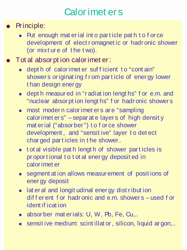
Calorimeters Principle:
! Put enough material into particle path to force development of electromagnetic or hadronic shower (or mixture of the two).
Total absorption calorimeter: ! depth of calorimeter sufficient to “contain”
showers originating from particle of energy lower than design energy
! depth measured in “radiation lengths” for e.m. and “nuclear absorption lengths” for hadronic showers
! most modern calorimeters are “sampling calorimeters” – separate layers of high density material (“absorber”) to force shower development, and “sensitive” layer to detect charged particles in the shower.
! total visible path length of shower particles is proportional to total energy deposited in calorimeter
! segmentation allows measurement of positions of energy deposit
! lateral and longitudinal energy distribution different for hadronic and e.m. showers – used for identification
! absorber materials: U, W, Pb, Fe, Cu,..! sensitive medium: scintillator, silicon, liquid argon,..
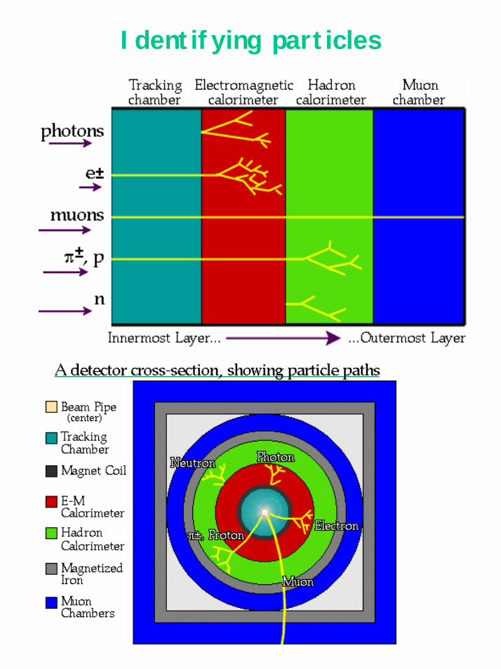
Identifying particles
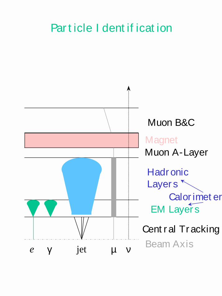
Particle Identification
Beam AxisCentral Tracking
EM Layers
HadronicLayers
Muon A-LayerMagnetMuon B&C
Calorimeter
e γ jet µ ν
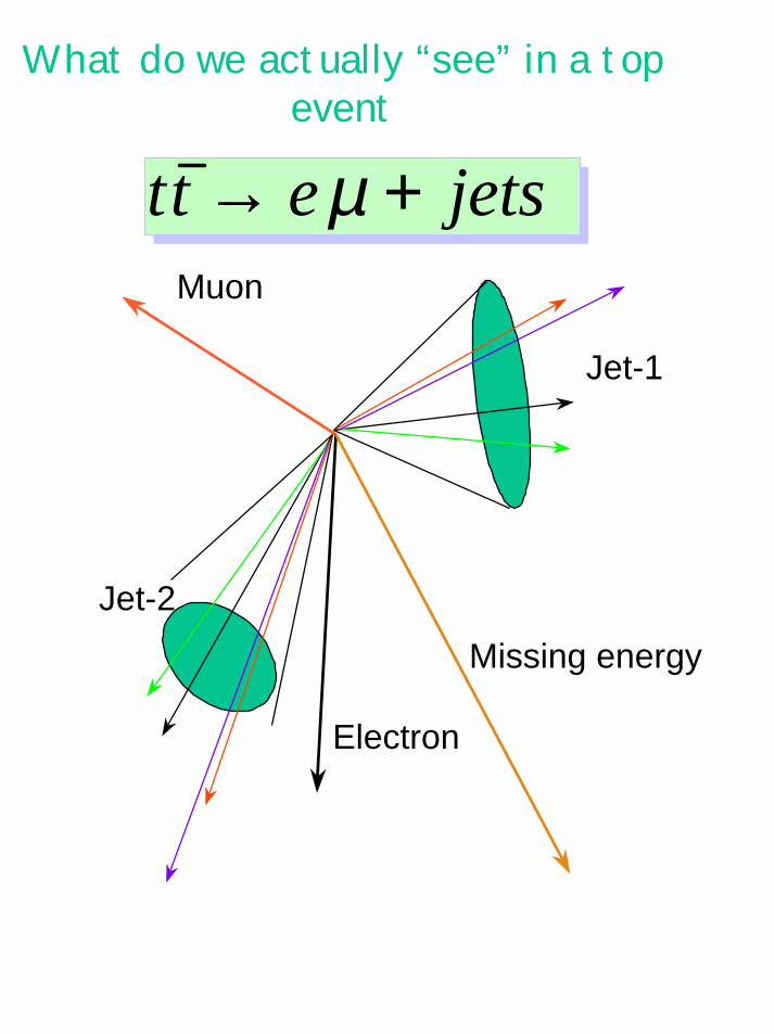
What do we actually “see” in a top event
Muon
Electron
Jet-1
Jet-2Missing energy
jetsett +→ µ
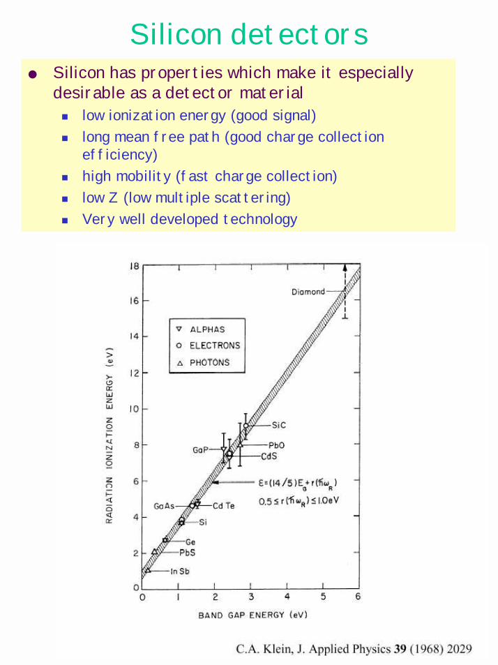
Silicon detectors Silicon has properties which make it especially
desirable as a detector material! low ionization energy (good signal)! long mean free path (good charge collection
efficiency)! high mobility (fast charge collection)! low Z (low multiple scattering)! Very well developed technology
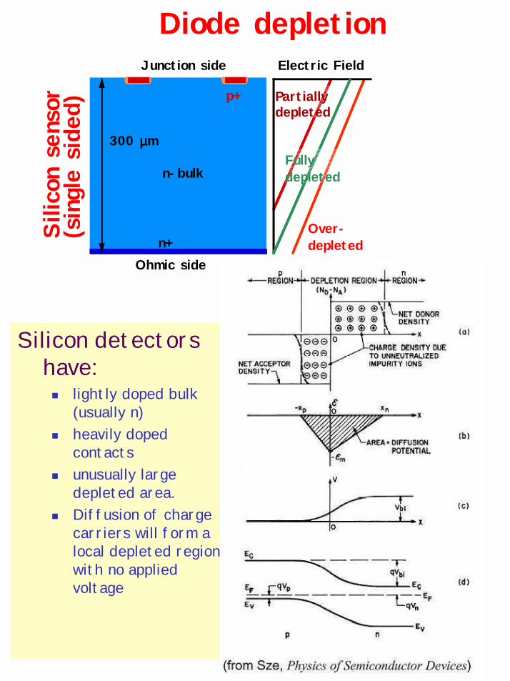
Diode depletion
Silicon detectors have:! lightly doped bulk
(usually n) ! heavily doped
contacts! unusually large
depleted area.! Diffusion of charge
carriers will form a local depleted region with no applied voltage
p+
n-bulk
n+
Junction side
Ohmic side
Electric Field
Partially depleted
300 µµµµmFully depleted
Over-depleted
Silic
on s
enso
r(single
side
d)
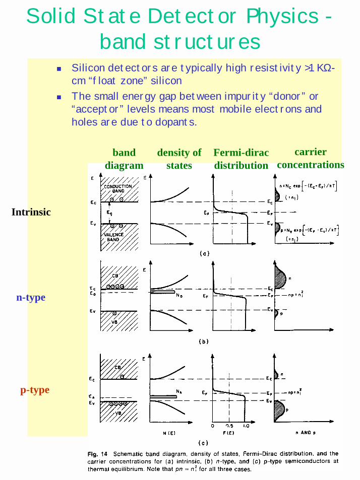
Solid State Detector Physics -band structures
! Silicon detectors are typically high resistivity >1 KΩ-cm “float zone” silicon
! The small energy gap between impurity “donor” or “acceptor” levels means most mobile electrons and holes are due to dopants.
Intrinsic
n-type
p-type
banddiagram
density ofstates
Fermi-diracdistribution
carrierconcentrations
p+
n
n+
Junction side
Ohmic side
300 µµµµm
Electric Field
Overdepleted
partiallydepleted
Charge density
Fullydepleted
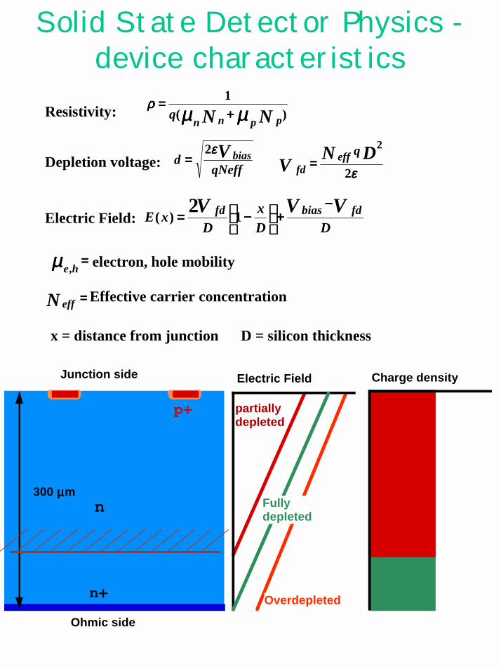
Solid State Detector Physics -device characteristics
Resistivity:
εεεε2
2DNVqeff
fd ====
)(1
NN ppnnq µµµµµµµµ
ρρρρ++++
====
Depletion voltage:
Electric Field:DD
xD
xEVVV fdbiasfd −−−−
++++
−−−−==== 1)(
2
====µµµµ he, electron, hole mobility
Effective carrier concentration====N eff
x = distance from junction D = silicon thickness
qNeffd V biasεεεε2
====
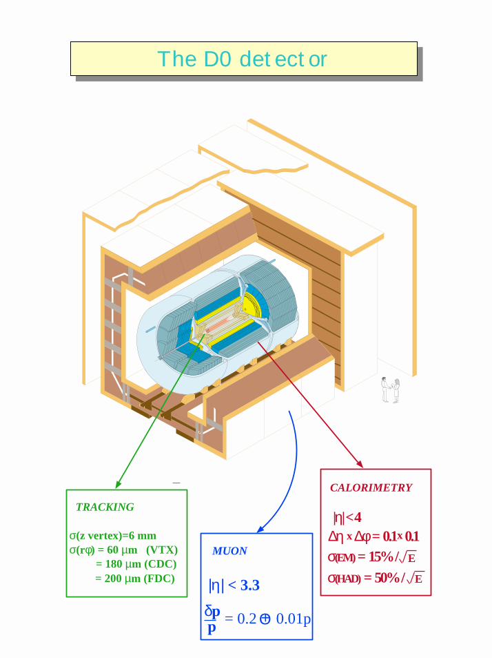
δpp O
|η| < 4
σ(EM) = 15% / σ(HAD) = 50% /
∆η ∆φ = 0.1 0.1E
x xσ(z vertex)=6 mmσ(rφ) = 60 µm (VTX)
= 180 µm (CDC)= 200 µm (FDC)
TRACKING
E
CALORIMETRY
= 0.2 0.01p+
|η| < 3.3
MUON
DO Detector/
The D0 detectorThe D0 detector
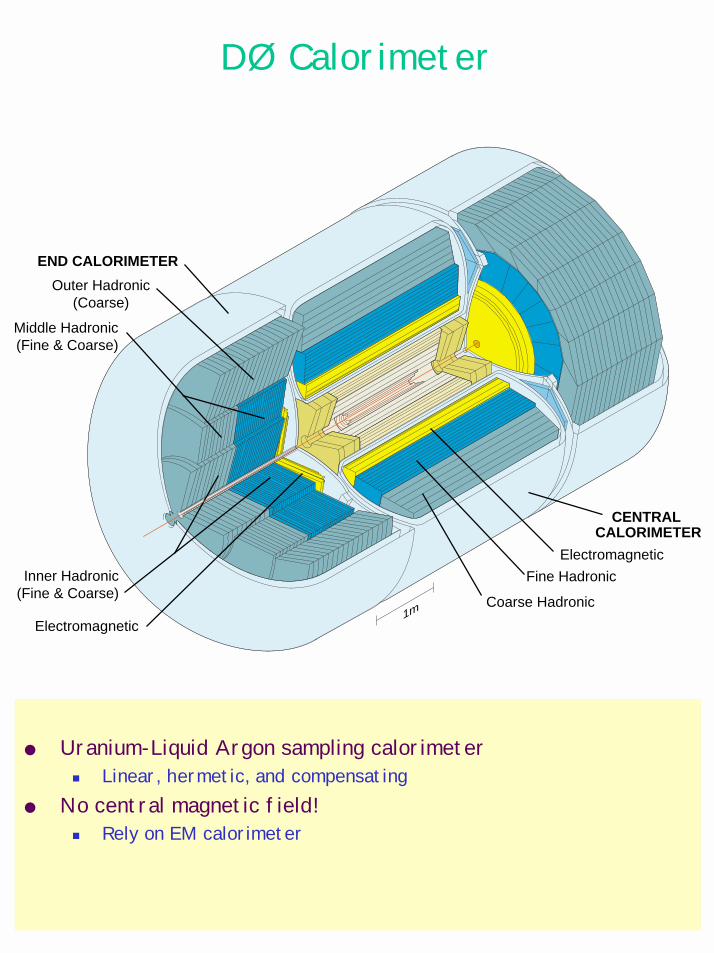
1m
CENTRAL CALORIMETER
END CALORIMETER
Outer Hadronic(Coarse)
Middle Hadronic(Fine & Coarse)
Inner Hadronic(Fine & Coarse)
Electromagnetic
Coarse Hadronic
Fine Hadronic
Electromagnetic
DØ Calorimeter
Uranium-Liquid Argon sampling calorimeter! Linear, hermetic, and compensating
No central magnetic field!! Rely on EM calorimeter
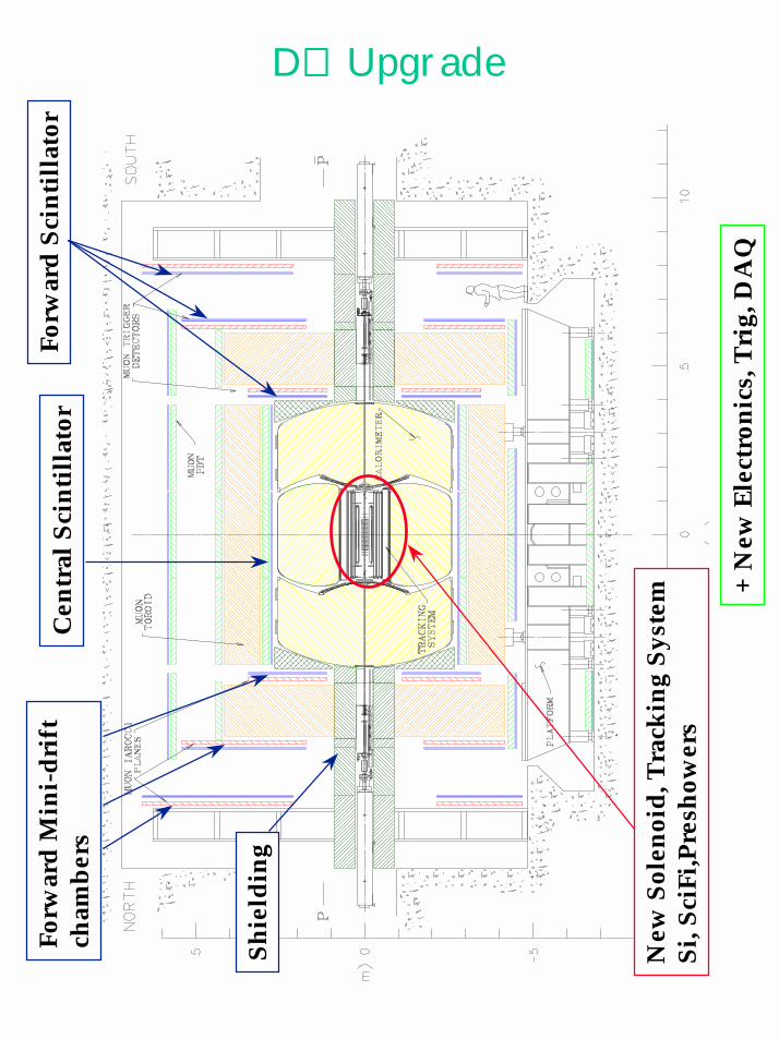
D∅∅∅∅ Upgrade
New
Sol
enoi
d, T
rack
ing
Syst
emSi
,Sci
Fi,P
resh
ower
s
Shie
ldin
g
Forw
ard
Min
i-dri
ft
cham
bers
Forw
ard
Scin
tilla
tor
Cen
tral
Scin
tilla
tor
+ N
ew E
lect
roni
cs, T
rig,
DA
Q
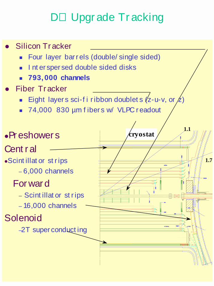
D∅∅∅∅ Upgrade Tracking
# Silicon Tracker! Four layer barrels (double/single sided)! Interspersed double sided disks! 793,000 channels
# Fiber Tracker ! Eight layers sci-fi ribbon doublets (z-u-v, or z)! 74,000 830 µm fibers w/ VLPC readout
#PreshowersCentral#Scintillator strips
– 6,000 channels
Forward– Scintillator strips– 16,000 channels
Solenoid–2T superconducting
cryostat1.1
1.7
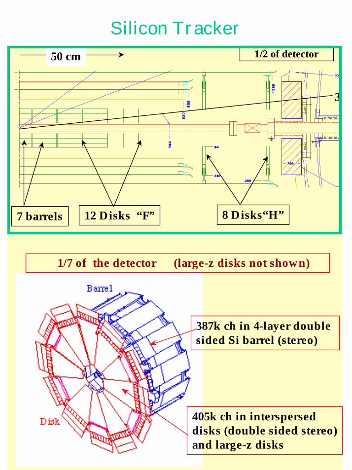
Silicon Tracker
7 barrels
50 cm
12 Disks “F” 8 Disks“H”
3
1/7 of the detector (large-z disks not shown)
387k ch in 4-layer double sided Si barrel (stereo)
405k ch in interspersed disks (double sided stereo)and large-z disks
1/2 of detector
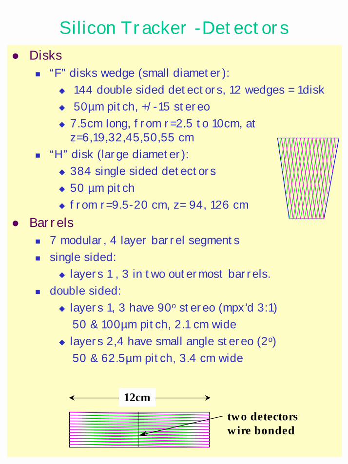
Silicon Tracker -Detectors# Disks
! “F” disks wedge (small diameter):" 144 double sided detectors, 12 wedges = 1disk" 50µm pitch, +/-15 stereo" 7.5cm long, from r=2.5 to 10cm, at
z=6,19,32,45,50,55 cm! “H” disk (large diameter):
" 384 single sided detectors" 50 µm pitch" from r=9.5-20 cm, z= 94, 126 cm
# Barrels! 7 modular, 4 layer barrel segments! single sided:
" layers 1 , 3 in two outermost barrels. ! double sided:
" layers 1, 3 have 90o stereo (mpx’d 3:1) 50 & 100µm pitch, 2.1 cm wide
" layers 2,4 have small angle stereo (2o) 50 & 62.5µm pitch, 3.4 cm wide
12cmtwo detectorswire bonded
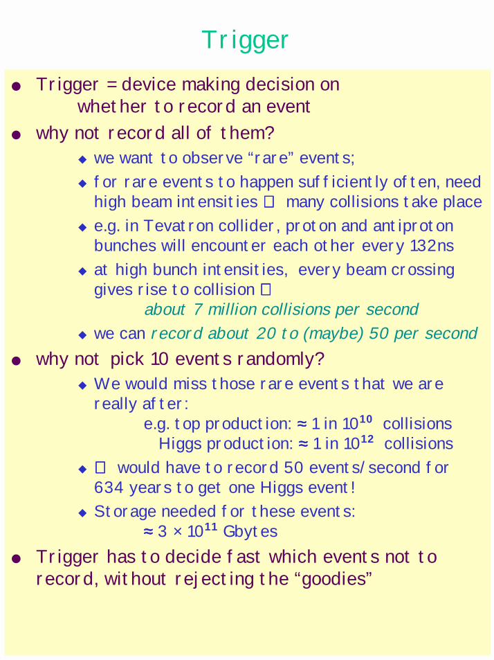
Trigger Trigger = device making decision on
whether to record an event why not record all of them?
" we want to observe “rare” events; " for rare events to happen sufficiently often, need
high beam intensities ⇒⇒⇒⇒ many collisions take place" e.g. in Tevatron collider, proton and antiproton
bunches will encounter each other every 132ns" at high bunch intensities, every beam crossing
gives rise to collision ⇒⇒⇒⇒about 7 million collisions per second
" we can record about 20 to (maybe) 50 per second why not pick 10 events randomly?
" We would miss those rare events that we are really after:
e.g. top production: ≈≈≈≈ 1 in 1010 collisions Higgs production: ≈≈≈≈ 1 in 1012 collisions
" ⇒⇒⇒⇒ would have to record 50 events/second for 634 years to get one Higgs event!
" Storage needed for these events: ≈≈≈≈ 3 × 10¹¹ Gbytes
Trigger has to decide fast which events not to record, without rejecting the “goodies”
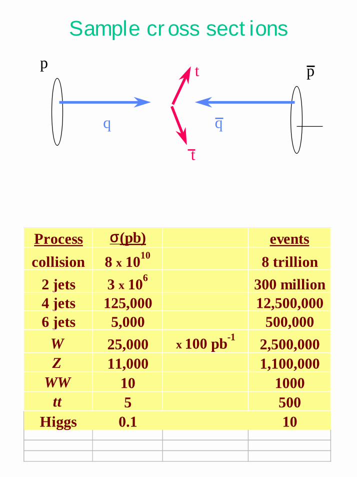
Sample cross sections
q
p p
q
t
t
Process σσσσ(pb) eventscollision 8 x 10¹⁰ 8 trillion
2 jets 3 x 10⁶ 300 million4 jets 125,000 12,500,0006 jets 5,000 500,000
W 25,000 x 100 pb-1 2,500,000Z 11,000 1,100,000
WW 10 1000tt 5 500
Higgs 0.1 10
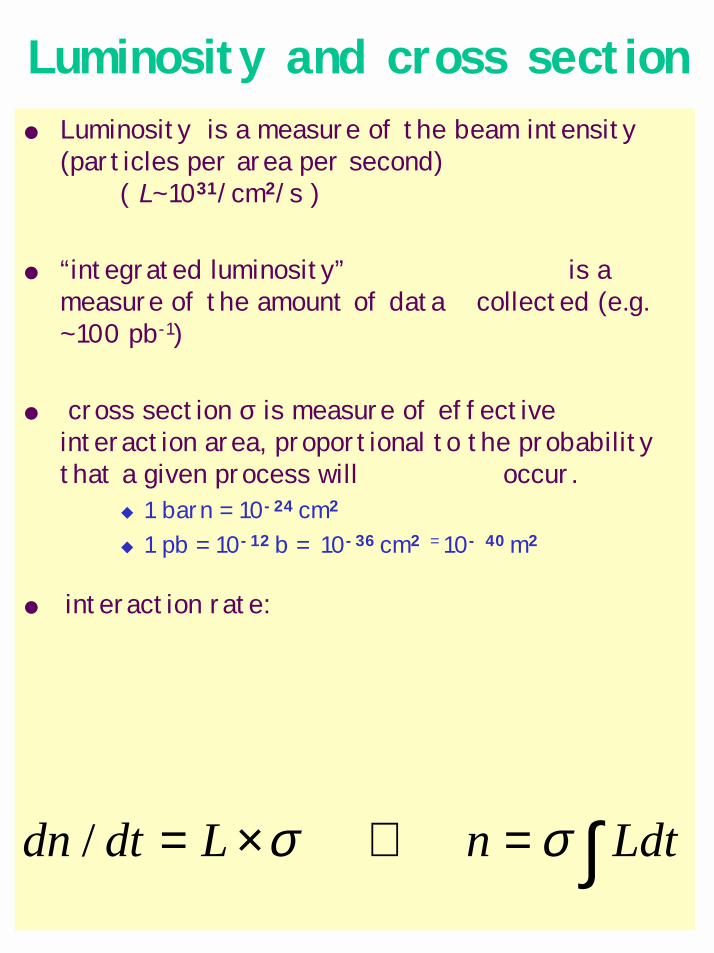
Luminosity and cross section Luminosity is a measure of the beam intensity
(particles per area per second) ( L~1031/cm2/s )
“integrated luminosity” is a measure of the amount of data collected (e.g. ~100 pb-1)
cross section σ is measure of effective interaction area, proportional to the probability that a given process will occur.
" 1 barn = 10-24 cm2
" 1 pb = 10-12 b = 10-36 cm2 = 10- 40 m2
interaction rate:
∫=⇒×= LdtnLdtdn σσ /
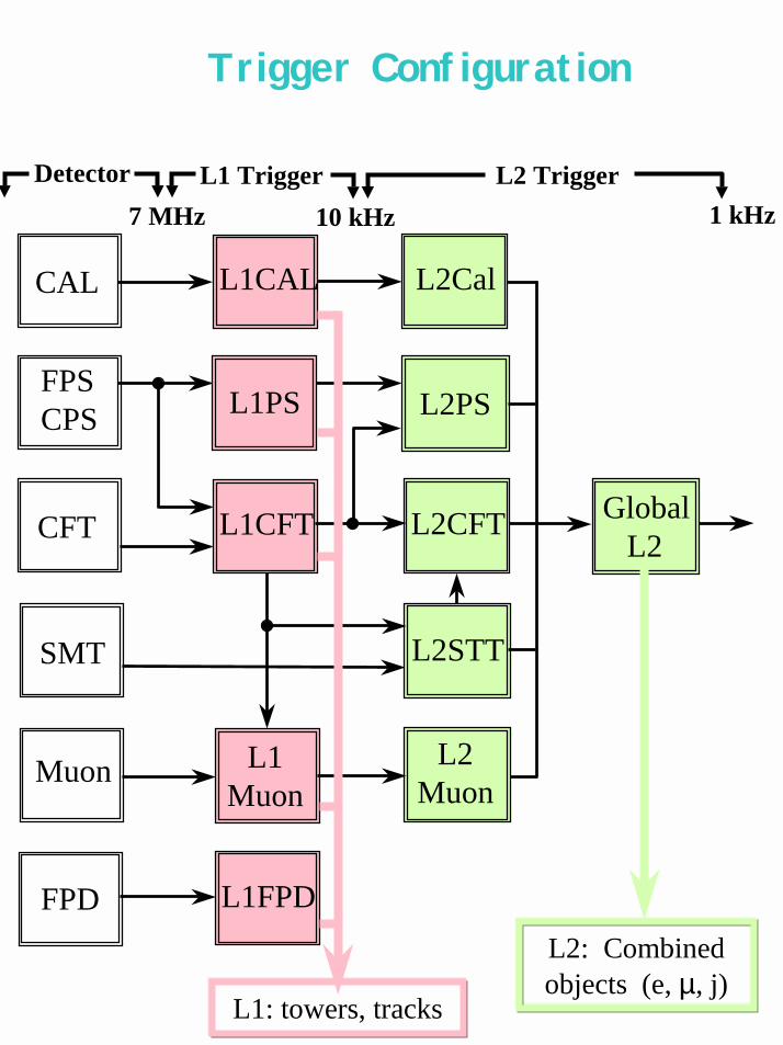
Trigger Configuration
L2: Combined objects (e, µ, j)
L1: towers, tracks
L1CAL
L2STT
GlobalL2
L2CFT
L2PS
L2Cal
L1PS
L1CFT
L2Muon
L1Muon
L1FPD
Detector L1 Trigger L2 Trigger7 MHz 10 kHz 1 kHz
CAL
FPSCPS
CFT
SMT
Muon
FPD
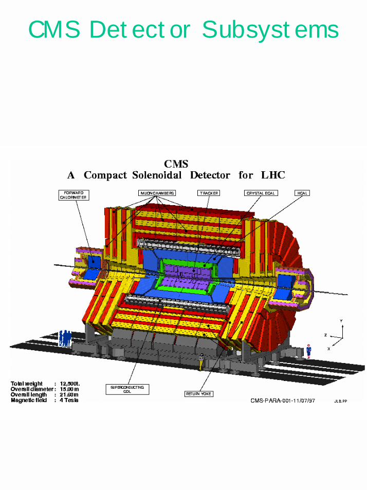
CMS Detector Subsystems
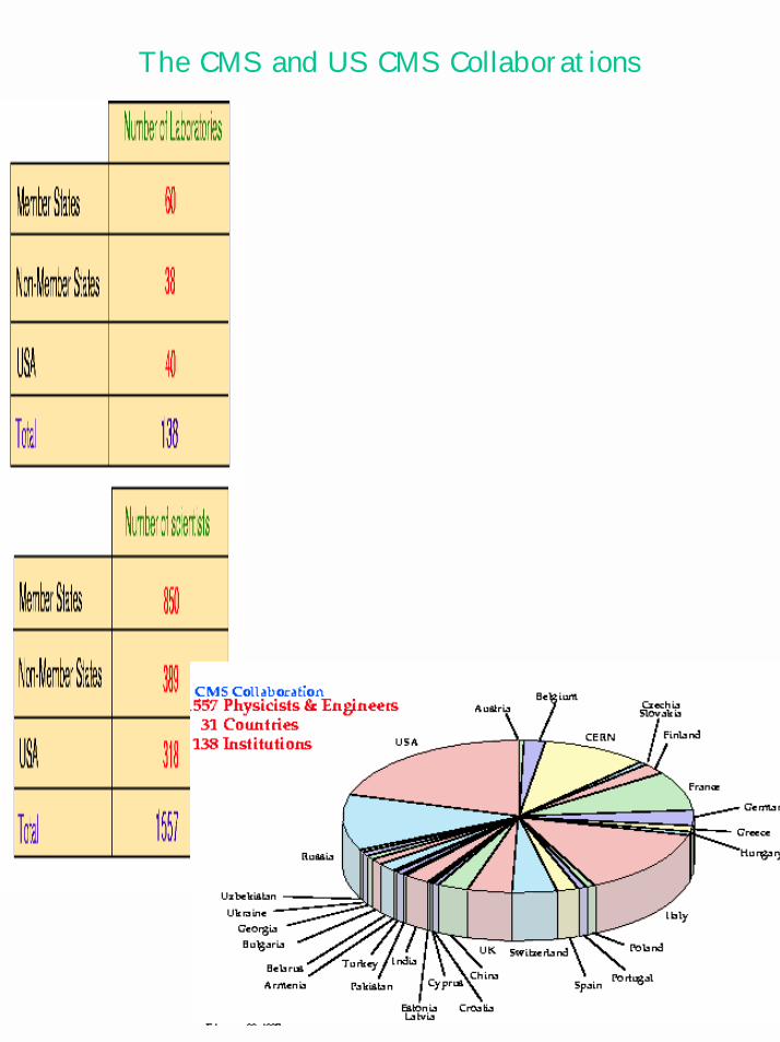
The CMS and US CMS Collaborations
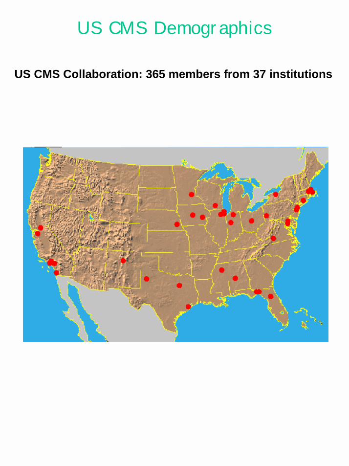
US CMS Demographics
US CMS Collaboration: 365 members from 37 institutions
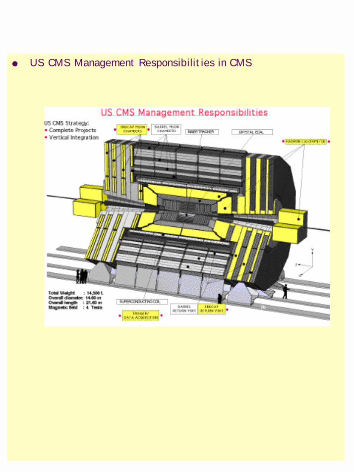
US CMS Management Responsibilities in CMS
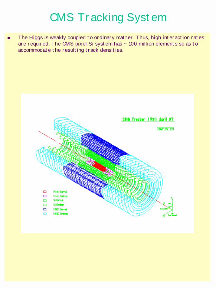
CMS Tracking System The Higgs is weakly coupled to ordinary matter. Thus, high interaction rates
are required. The CMS pixel Si system has ~ 100 million elements so as to accommodate the resulting track densities.
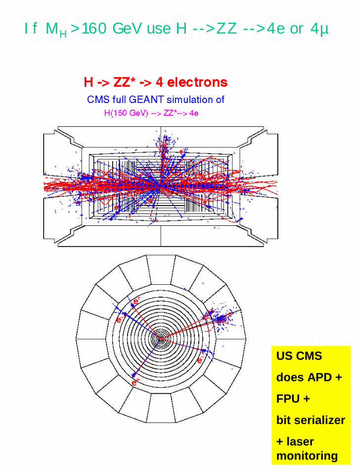
If MH > 160 GeV use H --> ZZ --> 4e or 4µ
US CMS
does APD +
FPU +
bit serializer
+ laser monitoring
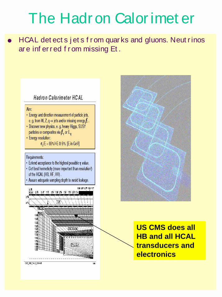
The Hadron Calorimeter HCAL detects jets from quarks and gluons. Neutrinos
are inferred from missing Et.
US CMS does all HB and all HCAL transducers and electronics
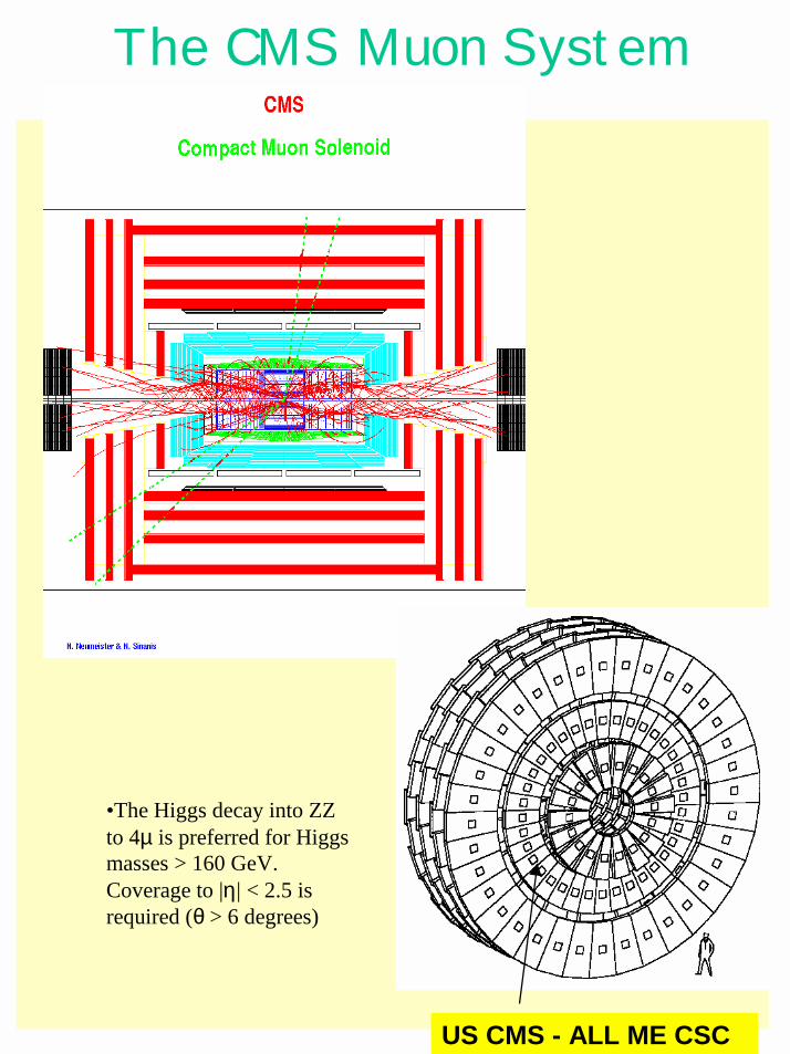
The CMS Muon System
US CMS - ALL ME CSC
•The Higgs decay into ZZ to 4µ is preferred for Higgs masses > 160 GeV. Coverage to |η| < 2.5 is required (θ > 6 degrees)
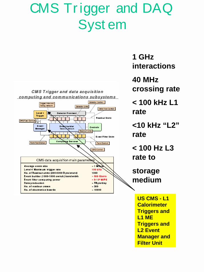
CMS Trigger and DAQ System
1 GHz interactions
40 MHz crossing rate
< 100 kHz L1 rate
<10 kHz “L2” rate
< 100 Hz L3 rate to
storage medium
US CMS - L1 Calorimeter Triggers and L1 ME Triggers and L2 Event Manager and Filter Unit
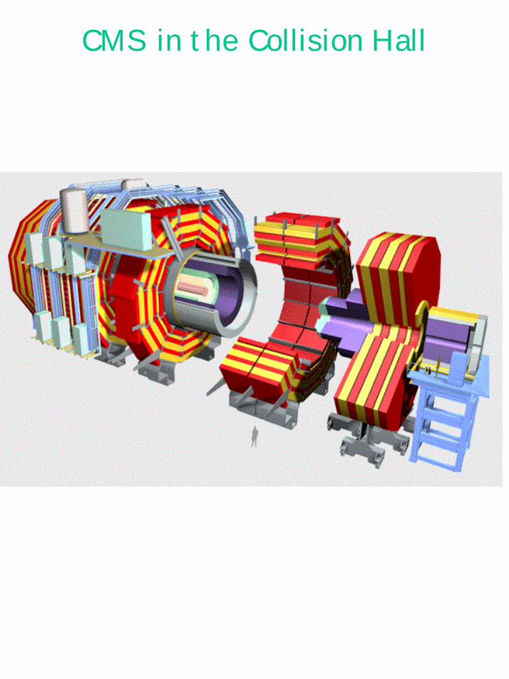
CMS in the Collision Hall