part # 18688 & 18689 phantom fuel pump / baffle...
TRANSCRIPT
AEROMOTIVE Part # 18688 & 18689
Phantom Fuel Pump / Baffle System For Tank Depths 6"-11"
INSTALLATION INSTRUCTIONS Patent Pending
WARNING!
Always be aware of flammable situations. Drilling a nd grinding can be potential ignition sources. Extinguish all open fla mes, prohibit smoking and eliminate all sources of ignition in the area of th e vehicle and workspace before proceeding with the installation. Ensure you are wo rking in a well ventilated area with an approved fire extinguisher nearby.
WARNING!
Installation of this product requires modification to a fuel tank, failure to satisfy all safety considerations will result in fi re, explosion, injury and/or loss of life to yourself and/or others.
WARNING!
Mechanical and hydraulic lifting devices can tip ov er or lower accidentally due to incorrect maneuvering or technical errors. A falling object can cause injury and/or loss of life to yourself and/or other s. When working under the vehicle always use stands and ensure that the groun d or floor is stable and level. Never crawl under a vehicle which is only supported by a jack.
WARNING!
The fuel system is under pressure. Do not open the fuel system until the pressure has been relieved. Refer to the appropriat e vehicle service manual for the procedure and precautions for relieving the fue l system pressure .
CAUTION!
When installing this product always wear safety gla sses and other appropriate safety appeal. A drilling operation wil l cause flying metal chips. Flying metal chips can cause eye injury.
CAUTION:
Installation of this product requires detailed know ledge of automotive systems and repair procedures. We recommend that this insta llation be carried out by a qualified automotive technician. Careless installat ion of this product can result in damge to the product, injury or loss of life to you rself and/or others.
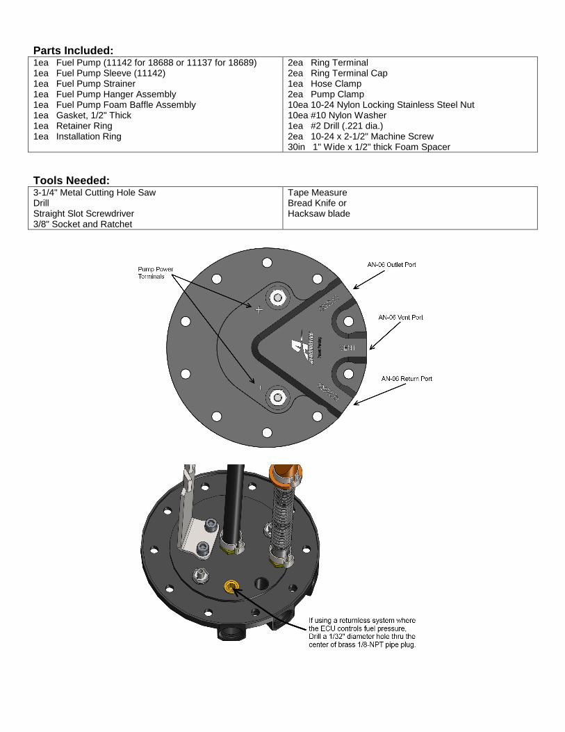
Parts Included: 1ea Fuel Pump (11142 for 18688 or 11137 for 18689) 1ea Fuel Pump Sleeve (11142) 1ea Fuel Pump Strainer 1ea Fuel Pump Hanger Assembly 1ea Fuel Pump Foam Baffle Assembly 1ea Gasket, 1/2" Thick 1ea Retainer Ring 1ea Installation Ring
2ea Ring Terminal 2ea Ring Terminal Cap 1ea Hose Clamp 2ea Pump Clamp 10ea 10-24 Nylon Locking Stainless Steel Nut 10ea #10 Nylon Washer 1ea #2 Drill (.221 dia.) 2ea 10-24 x 2-1/2" Machine Screw 30in 1" Wide x 1/2" thick Foam Spacer
Tools Needed: 3-1/4" Metal Cutting Hole Saw Drill Straight Slot Screwdriver 3/8" Socket and Ratchet
Tape Measure Bread Knife or Hacksaw blade
The enclosed Aeromotive fuel pump assembly utilizes an o-ring sealed AN-06 style feed, return and vent ports. These ports seal with o-rings; these ports are NOT PIPE THREAD and utilize NO THREAD SEALANT . The fuel pump used in this tank is either the Aeromotive Stealth 340 (part # 11142) for kit 18688 or the Aeromotive Stealth (part# 11137) for kit 11189. To insure proper pump function and life, we strongly recommend the following:
• Utilize AN-06 (EFI) and AN-08 (carb) size high pres sure fuel lines, fittings and o-rings for all conne ctions
from the fuel tank to the engine. • Install a 10 micron post-filter (Aeromotive p/n 123 01 or 12321). • Install a remote-mount rollover valve. It must be mounted in a vertical position and mounted as high or
higher than your filler tube. • Fuel pump wiring should be 10 gauge wire and trigge red with a relay rated at a minimum of 20 amps
(Aeromotive fuel pump wiring kit 16301). • A return style regulator must be used with the exce ption of running an ECU that supports a returnless
systems where the ECU controls fuel pressure via PW M. (Aeromotive p/n 13105, 13109 or 13129 for EFI, 13204 for carb).
Failure to follow the above recommendations may result in fuel leakage, bursting of the fuel lines, poor vehicle performance and/or decreased fuel pump life! Improper installation will void all warranties for this product! Pump Specifications:
18688 Kit (Pump #11142) 18689 Kit (Pump #11137) Outlet pressure/typical flow:
Continuous Operating Range:
Pump internal By-Pass Pressure: Current Draw:
10 psi / 408 LPH @ 13.5 V 40 psi / 340 LPH @ 13.5 V 60 psi / 284 LPH @ 13.5 V 5 psi – 65 psi @ 13.5 V 105 psi 13 amps @ 40 psi
10 psi / 272 LPH @ 13.5 V 40 psi / 215 LPH @ 13.5 V 60 psi / 189 LPH @ 13.5 V 5 psi – 65 psi @ 13.5 V 80 psi 8.3 amps @ 40 psi
Aeromotive Commonly Used Fittings 15606 AN-06 ORB to AN-06 Flare (Inlet/outlet/vent fitting) 15649 AN-06 ORB to AN-08 Flare (Inlet/outlet/vent fitting) 15609 AN-10 ORB to AN-06 Flare (fuel filter fitting) 15610 AN-10 ORB to AN-08 Flare (fuel filter fitting)
For AN-06 fuel lines For AN-08 fuel lines For AN-06 fuel lines For AN-08 fuel lines
Aeromotive AN-10 Fuel Filter P/N’s 12301 Red 10 micron Fuel Filter 12321 Black 10 micron Fuel Filter 12351 Chrome 10 micron Fuel Filter 12335 Red 40 micron Fuel Filter 12305 Fuel Filter Bracket Aeromotive Electrical Components 16301 Fuel Pump Wiring Kit 16306 Fuel Pump Speed Controller
12304 Red 100 micron Fuel Filter 12324 Black 100 Micron Fuel Filter 12354 Chrome 100 micron Fuel Filter 12331 Black 100 micron Fuel Filter w/ Shutoff Valve
Aeromotive system components are not legal for sale or use on emission controlled motor vehicles.
The following steps are typical of most installatio ns:
1. Once the engine has been allowed to cool, disconnect the negative battery cable and relieve the fuel system pressure, referring to the appropriate vehicle service manual for the procedure and precautions for doing so.
2. Raise the vehicle on stable level ground and support it with jack stands.
3. Referring to the appropriate vehicle service manual for instructions, drain, disconnect any electrical and fuel
component connections and remove the OEM fuel tank. The removal of the vehicles exhaust system may be necessary for fuel tank removal.
This Aeromotive Phantom Fuel Pump System is intende d to be installed into a NEW fuel tank that does NOT, and has NEVER contained fuel. If you choose to install this product into a fuel t ank that has had fuel introduced to it, proceed at your own risk. The fuel tank must be professionally cleaned to rem ove all traces of any combustible fluids. Failure to properly clean and r emove all combustible fluids from the fuel tank will result in injury or loss of life to yourself and/or others.
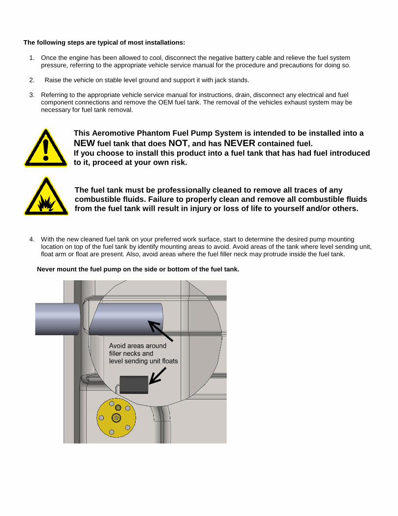
4. With the new cleaned fuel tank on your preferred work surface, start to determine the desired pump mounting location on top of the fuel tank by identify mounting areas to avoid. Avoid areas of the tank where level sending unit, float arm or float are present. Also, avoid areas where the fuel filler neck may protrude inside the fuel tank.
Never mount the fuel pump on the side or bottom of the fuel tank.
5. Secondly, locate and avoid areas of the top of the fuel tank that might contact the bottom of the vehicle frame rails, supports or floor pan.
6. Now that you have identified the areas on the fuel tank to avoid, you can narrowed this down further by identifying
the orientation of the fuel pump outlet cap how you would like to route the electrical and fuel lines. Note: Ensure that you mount the fuel pump at the de epest possible area of the fuel tank.
7. If the top of the tank is corrugated or has ribs on the desired mounting surface, the included gasket will compress
and form to the ribs up to 1/4" deep, for extreme cases where the ribs are deeper or oddly shaped the use of a fuel resistant sealant such as, Dow Corning 730 fluorosilicone RTV, or additional fabrication may be necessary. Do not use silicone gasket sealant as it is not fue l resistant.
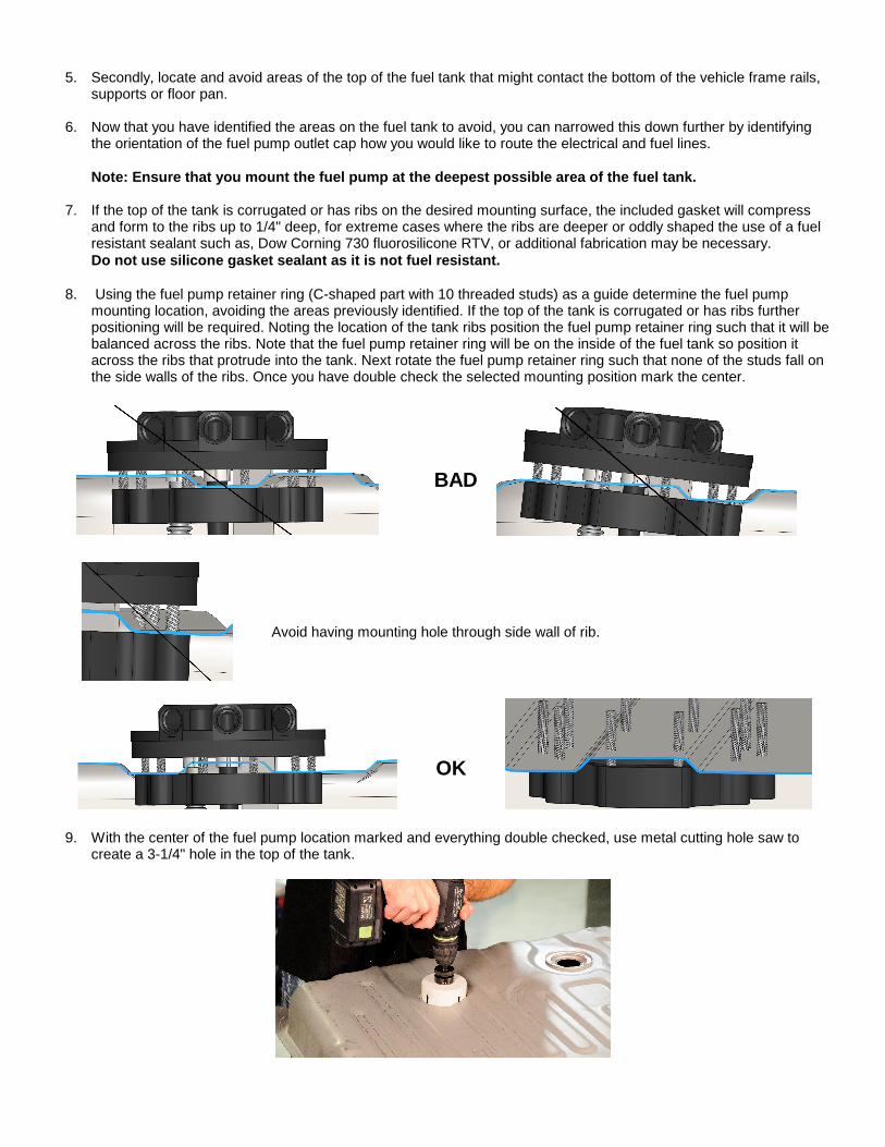
8. Using the fuel pump retainer ring (C-shaped part with 10 threaded studs) as a guide determine the fuel pump
mounting location, avoiding the areas previously identified. If the top of the tank is corrugated or has ribs further positioning will be required. Noting the location of the tank ribs position the fuel pump retainer ring such that it will be balanced across the ribs. Note that the fuel pump retainer ring will be on the inside of the fuel tank so position it across the ribs that protrude into the tank. Next rotate the fuel pump retainer ring such that none of the studs fall on the side walls of the ribs. Once you have double check the selected mounting position mark the center.
BAD
Avoid having mounting hole through side wall of rib.
OK
9. With the center of the fuel pump location marked and everything double checked, use metal cutting hole saw to
create a 3-1/4" hole in the top of the tank.
10. Place the included "installation ring" over the 3-1/4" hole so the raised register drops into it. Now rotate the ring until the bolt pattern is in the predetermined alignment. If the tank is corrugated or has ribs, rotate or clock the installation ring to ensure that none of the holes on the bolt pattern would have to be drilled into the side walls of the ribs.
11. With the installation ring correctly clocked in place, use the included #2 drill bit and drill one of the bolt pattern holes.
12. Place one of the included 10-24 x 2-1/2" screws in the above hole to help hold the index ring for further drilling.
13. With the installation ring still in place, drill a second hole, directly across (180-degrees) from the first.
14. Place the second 10-24 x 2-1/2" screw in the above second hole.
15. With the installation ring still held in place by the first two alignment screws, drill the remaining 8 holes.
16. Remove the installation ring and two alignment screws.
17. Using the fuel pump retainer ring, align the studs with the newly drilled holes and check for proper fit.
18. Remove any burrs that where created during the drilling operations above.
19. Carefully clean any debris from inside the fuel tank, a good shop-vac can be very helpful here.
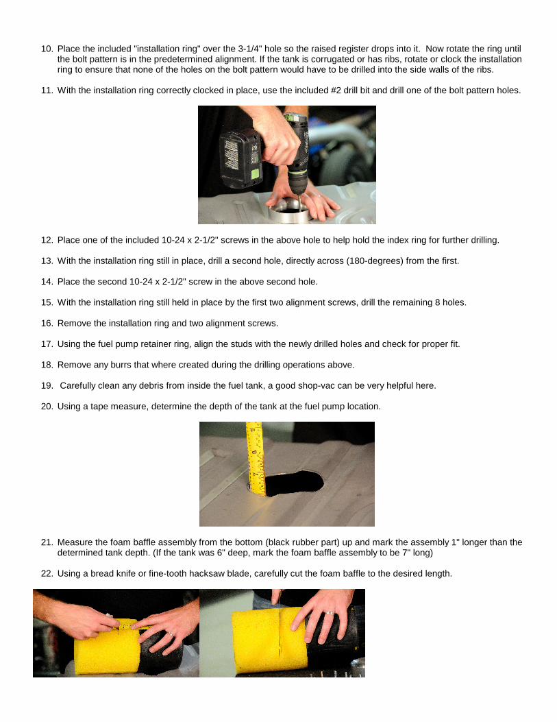
20. Using a tape measure, determine the depth of the tank at the fuel pump location.
21. Measure the foam baffle assembly from the bottom (black rubber part) up and mark the assembly 1" longer than the determined tank depth. (If the tank was 6" deep, mark the foam baffle assembly to be 7" long)
22. Using a bread knife or fine-tooth hacksaw blade, carefully cut the foam baffle to the desired length.
23. Install the fuel pump retainer ring into the fuel tank from the inside. The C-shape allows the ring to be inserted through the smaller hole, to the inside of the tank, and the studs pushed up through the holes drilled in steps 11-15.
24. Place the installation ring over the retaining ring studs that now protrude from the top of the tank. With the foam
baffle fully inserted into the bladder/cup, Compress the baffle assembly, and insert it through the installation ring into the tank being careful not to cut the assembly or your hands on the tank edge. Once the baffle assembly is in the tank, manipulate it until it’s centered within the opening.
25. NOTE: COMPLETE THIS STEP ONLY IF YOU PLAN ON USING A RETURNLESS FUEL SYSTEM where the ECU uses PWM to control fuel pressure. In this case you must drill a 1/32" hole thru the pipe plug indicated below. If you are planning on using a traditional, return style fuel system please skip this step If you are unsure what your system requires, please contact your EFI system manufacturer or Aeromotive for assistance.
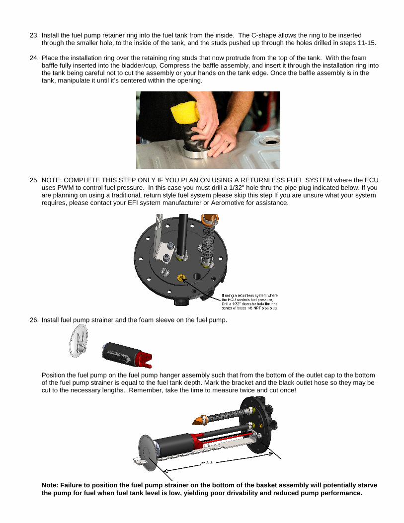
26. Install fuel pump strainer and the foam sleeve on the fuel pump.
Position the fuel pump on the fuel pump hanger assembly such that from the bottom of the outlet cap to the bottom of the fuel pump strainer is equal to the fuel tank depth. Mark the bracket and the black outlet hose so they may be cut to the necessary lengths. Remember, take the time to measure twice and cut once!
Note: Failure to position the fuel pump strainer on the bottom of the basket assembly will potentially starve the pump for fuel when fuel tank level is low, yiel ding poor drivability and reduced pump performance.
27. Cut the black outlet hose to the desired length.
28. Using a metal cutting saw cut the bracket to the desired length, removing enough at the bottom to ensure that the
end of the bracket will not contact the fuel pump strainer.
29. Using the small hose clamp attach the black outlet hose to the fuel pump and tighten.
30. Using the two larger hose clamps attach the pump to the pump bracket and tighten. The clamps should be positioned in the notches of the bracket.
31. Plug the electrical connector(s) into the pump and tuck the wire out of the way, for kit p/n 18689 the positive
connector is the .250" wide terminal and the negati ve terminal is .188" wide .
32. Install the provided gasket onto the threaded studs on the fuel pump retaining ring.
33. If the top of the tank is corrugated or has ribs on the desired mounting surface, the included gasket will compress and form to the ribs up to 1/4" deep. In extreme cases where the ribs are deeper than ¼”, or oddly shaped, the use of a fuel resistant sealant such as, Dow Corning 730 fluorosilicone RTV, or additional fabrication may be necessary.
Do not use silicone gasket sealant as it is not fue l resistant.
34. With the fuel pump hanger is fully assembled and the gasket in place, ease the pump hanger assembly into the baffle assembly inside the fuel tank. Rotate the billet fuel pump hanger assembly to orient the fuel line and vent connections in the desired orientation and drop the hanger onto the retaining ring studs.
35. Press down firmly on the top of the pump assembly to compress the gasket. Start two of the 10-24 lock nuts on a pair of studs 180- degree apart. Tighten these two nuts until the remaining studs are approximately 1/4" exposed.
36. With the remaining 8 studs exposed approximately 1/4", place one of the #10 white nylon sealing washers on each
of the studs followed by a 10-24 locking nut.
37. Remove the first two lock nuts used to help compress the gasket. Place one of the #10 white nylon sealing washers on each of these two studs, followed by reinstalling the 10-24 locking nut.
38. With all 10 studs now having a #10 white nylon sealing washer and a locking nut, slowly tighten using a crisscross
pattern until the gasket forms to the tank surface.
39. Prep the new tank by making all the necessary connection (feed, return, vent and electrical) before placing tank in vehicle. In most cases, once the tank is placed in the vehicle these connection will not be accessible. For electrical wiring refer to Figure 2-1.
Note: Tank vent must be at least 6” above the top o f the tank if a roll-over valve is used (highly recommended).
40. Reinstall the fuel tank in the vehicle. In some cases it may be necessary to space the fuel tank down to allow
additional clearance for the new pump outlet, top plate and fittings. 1/2" thick foam material is provided and should be divided and installed at the top of the tank on either side, between the tank and the trunk floor,to help space the fuel tank down if necessary. Additional fabrication may be necessary to gain clearance in extreme cases.
41. Now route the feed and return line under the vehicle and secure them to the chassis. It’s recommended to install a post-filter between the fuel pump and the engine (see Aeromotive part # 12301/12321). Place the filter in a location that is clear of suspension and exhaust system components and easy to get to for servicing.
Note: Be sure to route all fuel lines clear of any moving suspension or drivetrain components, and any exhaust components! Protect fuel lines from abrasio n and road obstructions or debris.
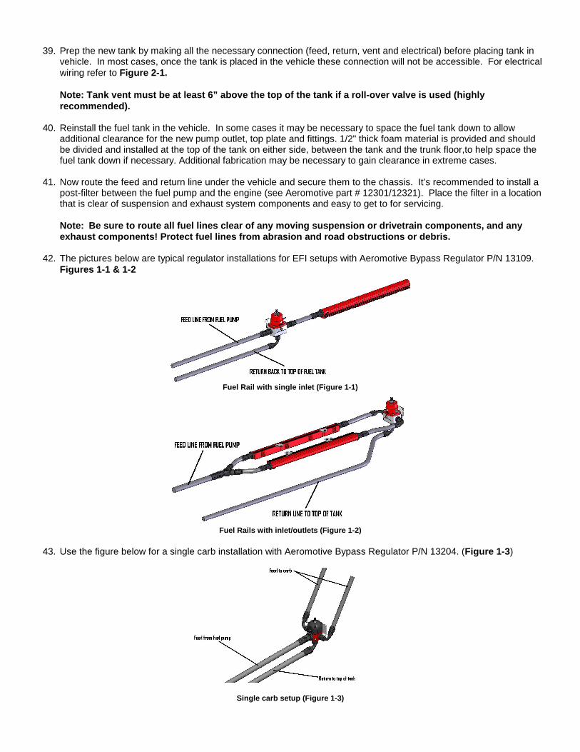
42. The pictures below are typical regulator installations for EFI setups with Aeromotive Bypass Regulator P/N 13109.
Figures 1-1 & 1-2
Fuel Rail with single inlet (Figure 1-1)
Fuel Rails with inlet/outlets (Figure 1-2)
43. Use the figure below for a single carb installation with Aeromotive Bypass Regulator P/N 13204. (Figure 1-3 )
Single carb setup (Figure 1-3)
Thanks for purchasing another quality product designed, engineered and manufactured in Kansas City, USA!
AEROMOTIVE, INC. 7805 Barton Street, Lenexa, KS 66214
913-647-7300 fax 913-647-7207
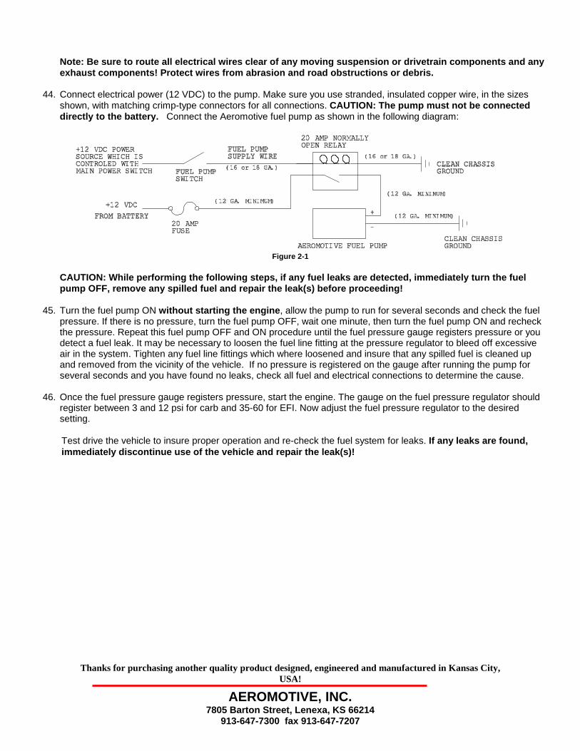
Note: Be sure to route all electrical wires clear o f any moving suspension or drivetrain components an d any exhaust components! Protect wires from abrasion and road obstructions or debris.
44. Connect electrical power (12 VDC) to the pump. Make sure you use stranded, insulated copper wire, in the sizes shown, with matching crimp-type connectors for all connections. CAUTION: The pump must not be connected directly to the battery. Connect the Aeromotive fuel pump as shown in the following diagram:
Figure 2-1
CAUTION: While performing the following steps, if a ny fuel leaks are detected, immediately turn the fu el pump OFF, remove any spilled fuel and repair the le ak(s) before proceeding!
45. Turn the fuel pump ON without starting the engine , allow the pump to run for several seconds and check the fuel
pressure. If there is no pressure, turn the fuel pump OFF, wait one minute, then turn the fuel pump ON and recheck the pressure. Repeat this fuel pump OFF and ON procedure until the fuel pressure gauge registers pressure or you detect a fuel leak. It may be necessary to loosen the fuel line fitting at the pressure regulator to bleed off excessive air in the system. Tighten any fuel line fittings which where loosened and insure that any spilled fuel is cleaned up and removed from the vicinity of the vehicle. If no pressure is registered on the gauge after running the pump for several seconds and you have found no leaks, check all fuel and electrical connections to determine the cause.
46. Once the fuel pressure gauge registers pressure, start the engine. The gauge on the fuel pressure regulator should register between 3 and 12 psi for carb and 35-60 for EFI. Now adjust the fuel pressure regulator to the desired setting. Test drive the vehicle to insure proper operation and re-check the fuel system for leaks. If any leaks are found, immediately discontinue use of the vehicle and repa ir the leak(s)!
Aeromotive, Inc. 7805 Barton Street, Lenexa, KS 66214 Phone: (913) 647-7300 Fax: (913) 647-7207
AEROMOTIVE, INC. LIMITED WARRANTY This Aeromotive Product, with proof of purchase dated on or after January 1, 2003, is warranted to be free from defects in materials and workmanship for a period of one year from the original date of purchase. No warranty claim will be valid without authentic, dated proof of purchase. This warranty is to the original retail purchaser and none other and is available directly from Aeromotive and not through any point of distribution or purchase. If a defect is suspected, the retail purchaser must contact Aeromotive directly to discuss the problem, possible solutions and obtain a Return Goods Authorization (RGA), if deemed necessary by the company. Please call 913-647-7300 and dial option 3 for the technical service dept. All returns must be shipped freight pre-paid to the company and with valid RGA before they will be processed. Aeromotive will examine any product returned with the proper authorization to determine if the failure resulted from a defect or from abuse, improper installation, misapplication or alteration. Aeromotive will then, at it’s sole discretion, return, repair or replace the product. If any Aeromotive product is determined defective, buyer’s exclusive remedy is limited in value to the sale price of the good. In no event shall Aeromotive be liable for incidental or consequential damages.
Aeromotive expressly retains the right to make changes and improvements in any product it manufactures and sells at any time. These changes and improvements may be made without notice at any time and without any obligation to change the catalogs or printed materials. Aeromotive expressly retains the right to discontinue at any time and without notice any Aeromotive product that it manufactures or sells. This warranty is limited and expressly limits any implied warranty to one year from the date of the original retail purchase on all Aeromotive products. No person, party or corporate entity other than Aeromotive shall have the right to: determine whether or not this Limited Warranty is applicable to any Aeromotive product, authorize any action whatsoever under the terms and conditions of this Limited Warranty, assume any obligation or liability of any nature whatsoever on behalf of Aeromotive under the terms and conditions of this Limited Warranty. This Limited Warranty covers only the product itself and not the cost of installation or removal. This Limited Warranty is in lieu of and expressly excludes any and all other warranties, expressed or implied. This Limited Warranty gives you specific legal rights, and you may also have other rights which vary from state to state.