parallel and distributed computing techniques in biomedical
TRANSCRIPT

PARALLEL AND DISTRIBUTED COMPUTING
TECHNIQUES IN BIOMEDICAL ENGINEERING
CAO YIQUN
(B.S., Tsinghua University)
A THESIS SUBMITTED
FOR THE DEGREE OF MASTER OF ENGINEERING
DEPARTMENT OF ELECTRICAL AND COMPUTER ENGINEERING
AND
DIVISION OF BIOENGINEERING
NATIONAL UNIVERSITY OF SINGAPORE
2005

National University of Singapore i
Declaration
The experiments in this thesis constitute work carried out by the candidate
unless otherwise stated. The thesis is less than 30,000 words in length, exclusive of
tables, figures, bibliography and appendices, and complies with the stipulations set
out for the degree of Master of Engineering by the National University of Singapore.
Cao Yiqun
Department of Electrical and Computer
Engineering
National University of Singapore
10 Kent Ridge Crescent, Singapore 119260

National University of Singapore ii
Acknowledgments
I would like to express sincere gratitude to Dr. Le Minh Thinh for his guidance
and support. I thank him also for providing me an opportunity to grow as a research
student and engineer in the unique research environment he creates.
I have furthermore to thank Dr. Lim Kian Meng for his advice and administrative
support and contribution to my study and research.
I am deeply indebted to Prof. Prof. Nhan Phan-Thien whose encouragement as
well as technical and non-technical advices have always been an important support
for my research. Special thanks to him for helping me through my difficult time of
supervisor change.
I would also like to express sincere thanks to Duc Duong-Hong for helping me
through many questions regarding biofluid and especially fiber suspensions
modelling.
Most importantly, my special thanks to my family and my girlfriend. Without
your support, nothing could be achievable.

National University of Singapore iii
Table of Contents
Chapter 1 Introduction...................................................................................1
1.1 Motivation.............................................................................................................. 2
1.2 Thesis Contributions .............................................................................................. 5
1.3 Thesis Outline ........................................................................................................ 8
Chapter 2 Background .................................................................................10
2.1 Definition: Distributed and Parallel Computing .................................................. 10
2.2 Motivation of Parallel Computing ....................................................................... 11
2.3 Theoretical Model of Parallel Computing ........................................................... 14
2.4 Architectural Models of Parallel Computer ......................................................... 15
2.5 Performance Models of Parallel Computing Systems ......................................... 21
2.6 Interconnection Schemes of Parallel Computing Systems .................................. 27
2.7 Programming Models of Parallel Computing Systems........................................ 31
Chapter 3 Overview of Hardware Platform and Software Environments
for Research in Computational Bioengineering ..........................................34
3.1 Hardware Platform............................................................................................... 34
3.2 Software Environments for Parallel Programming.............................................. 40
Chapter 4 Parallel Fiber Suspensions Simulation .......................................45
4.1 An Introduction to the Fiber Suspensions Simulation Problem........................... 46

National University of Singapore iv
4.2 Implementing the Parallel Velocity-Verlet Algorithm using Conventional
Method ....................................................................................................................... 48
4.3 Performance Study of Conventional Implementation.......................................... 52
4.4 Communication Latency and the Number of Processes ...................................... 55
4.5 Implementing the Parallel Fiber Suspensions Simulation with Communication
Overlap....................................................................................................................... 68
4.6 Results .................................................................................................................. 77
4.7 Conclusion ........................................................................................................... 85
Chapter 5 Parallel Image Processing for Laser Speckle Images .................87
5.1 Introduction to Laser Speckle Imaging Technique .............................................. 87
5.2 Previous Work...................................................................................................... 96
5.3 Parallelism of mLSI Algorithm............................................................................ 99
5.4 Master-worker Programming Paradigm............................................................. 100
5.5 Implementation .................................................................................................. 103
5.6 Results and Evaluation....................................................................................... 119
5.7 Conclusion ......................................................................................................... 127
Chapter 6 Conclusions and Suggestions for Future Work.........................129
6.1 Conclusions........................................................................................................ 129
6.2 Areas for Improvement ...................................................................................... 131
6.3 Automated Control Flow Rescheduling............................................................. 131
6.4 Programming Framework with Communication Overlap.................................. 133
6.5 Socket-based ACL Implementation ................................................................... 134

National University of Singapore v
6.6 MATLAB extension to ACL ............................................................................. 135
6.7 Summary ............................................................................................................ 136
Bibliography ..............................................................................................137

National University of Singapore vi
Abstract
Biomedical Engineering, usually known as Bioengineering, is among the fastest
growing and most promising interdisciplinary fields today. It connects biology,
physics, and electrical engineering, for all of which biological and medical
phenomena, computation, and data management play critical roles. Computation
methods are widely used in the research of bioengineering. Typical applications range
from numerical modellings and computer simulations, to image processing and
resource management and sharing. The complex nature of biological process
determines that the corresponding computation problems usually have a high
complexity and require extraordinary computing capability to solve them.
Parallel and Distributed computing techniques have proved to be effective in
tackling the problem with high computational complexity in a wide range of domains,
including areas of computational bioengineering. Furthermore, recent development of
cluster computing has made low-cost supercomputer built from commodity
components not only possible but also very powerful. Development of modern
distributed computing technologies now allows aggregating and utilizing idle
computing capability of loosely-connected computers or even supercomputers. This
means employing parallel and distributed computing techniques to support
computational bioengineering is not only feasible but also cost-effective.
In this thesis, we introduce our effort to utilize computer cluster for 2 types of
computational bioengineering problems, namely intensive numerical simulations of
National University of Singapore vii
fiber suspension modelling, and multiple-frame laser speckle image processing. Focus
has been put on identifying the main obstacles of using low-end computer clusters to
meet the application requirements, and techniques to overcome these problems.
Efforts have also been made to generate easy and reusable application frameworks
and guidelines on which similar bioengineering problems can be systematically
formulated and solved without loss of performance.
Our experiments and observations have shown that, computer clusters, and
specifically those with high-latency interconnection network, have major performance
problem in solving the 2 aforementioned types of computational bioengineering
problems, and our techniques can effectively solve these problems and make
computer cluster successfully satisfy the application requirements. Our work creates a
foundation and can be extended to address many other computationally intensive
bioengineering problems. Our experience can also help researchers in relevant areas
in dealing with similar problems and in developing efficient parallel programs
running on computer clusters.

National University of Singapore viii
List of Figures
Figure 2-1 A simplified view of the parallel computing model hierarchy ..................... 16
Figure 2-2 Diagram illustration of shared-memory architecture .................................... 17
Figure 2-3 Diagram illustration of distributed memory architecture.............................. 18
Figure 2-4 Typical speedup curve .................................................................................. 22
Figure 2-5 Illustrations of Simple interconnection schemes .......................................... 28
Figure 4-1 Division of a fluid channel into several subdomains .................................... 50
Figure 4-2 Pseudo code of program skeleton of fiber suspensions simulation .............. 50
Figure 4-3 Relationship between time variables defined for execution time analysis ... 60
Figure 4-4 Directed Graph illustrating calculation of execution time............................ 60
Figure 4-5 Simulation result: execution time versus number of processes .................... 63
Figure 4-6 (A) non-overlap versus (B) overlap: comparison of latency......................... 66
Figure 4-7 Extended pseudo-code showing the structure of main loop ......................... 72
Figure 4-8 Rescheduling result ....................................................................................... 75
Figure 4-9 Observed speedup and observed efficiency on zero-load system................. 80
Figure 4-10 Observed speedup and observed efficiency on non-zero load system........ 85
Figure 5-1 Basic setup of LSI with LASCA................................................................... 93
Figure 5-2 Master-worker paradigm............................................................................. 102
Figure 5-3 Illustration of top-level system architecture ............................................... 105
Figure 5-4 Illustration of master-work structure of speckle image processing system 107
Figure 5-5 Architecture of Abastract Communication Layer ....................................... 109
Figure 5-6 Flowchart of the whole program, master node logic, worker node logic, and assembler node logic. .......................................................................... 110

National University of Singapore ix
List of Tables
Table 4-1 Performance profiling on communication and computation calls.................. 54
Table 4-2 CPU times with and without the communication overlap applied................. 77
Table 4-3 Performance evaluation results: zero-load system ......................................... 81
Table 4-4 Performance evaluation results: non-zero load system (original load is 1) ... 85
Table 5-1 Time spent on blocking communication calls under different conditions ... 121
Table 5-2 Time spent on non-blocking communication subroutines with different data package sizes and receiver response delay time ........................................ 122
Table 5-3 Time spent on non-blocking communication calls under different conditions ................................................................................................... 123
Table 5-4 Time spent on processing 1 image frame when no compression is used ..... 125
Table 5-5 Comparison of different compression methods............................................ 126
Table 5-6 Time spent on processing 1 image frame when LZO compression is used . 127

Chapter 1 Introduction
The domain of this research is effectively utilizing parallel and distributed
computing technologies, especially computer clusters, to support computing demands
in biomedical research and practice. Two typical computational problems in
bioengineering field are numerical simulation, which is very common in research in
computational fluid dynamics; and biomedical image processing, which is
increasingly playing an essential role in research in diagnostic and clinical
experiments. The complexity of biological systems imposes severe requirements on
computing power and latency on both types of problems.
Parallel computing promises to be effective and efficient in tackling these
computation problems. However, parallel programming is different from and far more
complex than conventional serial programming, and building efficient parallel
programs is not an easy task. Furthermore, the fast evolution of parallel computing
implies algorithms to be changed accordingly, and the diversity of parallel computing
platforms also requires parallel algorithms and implementations to be written with
consideration on underlying hardware platform and software environment for research
issues in bioengineering.
In this thesis, we investigate how to effectively use the widely-deployed
computer cluster to tackle the computational problems in the aforementioned two
National University of Singapore 1

types of bioengineering research issues: numerical simulations of fiber suspension
modelling, and laser speckle image processing for blood flow monitoring. Computer
cluster imposes several challenges in writing efficient parallel programs for those two
types of applications, in terms of both coding time and run-time efficiencies. For
instance, relatively larger communication latency may hinder the performance of
parallel programs running on computer cluster, and it would be desirable if
programmers can optimize the communication by hand; however, that extra work
would make the programming task less systematic, more complex, and error prone.
We introduce several techniques to deal with these general problems of run-time
performance, which may widely present in other bioengineering applications.
Methods to reduce the programming task and to allow programmers to focus more on
computation logic are also proposed.
1.1 Motivation
Fundamental biology has achieved incredibly significant advancement in the past
few decades, especially at the molecular, cellular, and genomic levels. This
advancement results in dramatic increase in fundamental information and data on
mechanistic underpinnings of biological systems and activities. The real challenge is
now how to integrate information from as low as genetic levels to high levels of
system organization. Achievement of this will help both scientific understanding and
development of new biotechnologies. Engineering approaches - based on physics and
chemistry and characterized by measurement, modelling, and manipulation - have
been playing an important role in the synthesis and integration of information. The
National University of Singapore 2

combination of biological science research and engineering discipline has resulted in
the fast growing area of biomedical engineering, which is also known as
bioengineering.
Of the many methods of engineering principles, computational and numerical
methods have been receiving increasing emphasis in recent years. This is mainly
because of its physics and chemistry root, as well as the recent advancement of
computing technologies, which makes complex computation feasible, cost-efficient
and less time-consuming. As a result, computational bioengineering, which employs
computational and numerical methods in bioengineering research and industry, has
experienced fast adoption and development in the last few years.
The complex nature of biological system contributes to the large computation
complexity of these problems. Another important characteristic is the distribution of
data and instruments. These together inspire the use of parallel and distributed
computing in computational bioengineering. With this computing technique, a single
large-scale problem can be solved by dividing into smaller pieces to be handled by
several parallel processors, and by taking advantage of distributed specialized
computation resources, such as data sources and visualization instruments.
However, there are several challenges involved in using parallel and distributed
techniques in computational bioengineering. Firstly, efficient programs utilizing
parallel and distributed technique are far from easy development, especially for
medical doctors and practitioners whose trainings are not computer programming.
This is because programmers of parallel and distributed system, in addition to
specifying what values the program computes, usually need to specify how the
machine should organize the computation. In other words, programmers need to make
National University of Singapore 3

decision on algorithms as well as strategies of parallel execution. There are many
aspects to parallel execution of a program: to create threads, to start thread execution
on a processor, to control data transfer data among processors, and to synchronize
threads. Managing all these aspects properly on top of constructing a correct and
efficient algorithm is what makes parallel programming so hard.
When a computer cluster, the most popular and accessible parallel computing
facility, is used as the hardware platform, the relatively larger communication latency
is a further obstacle in achieving high performance. Practical experience usually
shows a threshold of the number of processors, beyond which the performance starts
degrading with larger number of processors.
Another important performance criterion, especially for clinical applications, is
whether a system is capable of supporting real-time operation. When this is
concerned, in addition to computing capacity, latency or lag, defined as the time it
takes to get the result after the input is available for the processing system, imposes
further performance requirements. When parallel computing is used, the coordination
among participating processors, although increases the computing capacity, will result
in larger latency.
There is also the challenge from the fact that biomedical engineering is a fast
evolving field, with dozens of methods available for each task, and with new methods
invented every day. It would be desirable to separate the computational logic from the
supporting code, such as thread creation and communication. Parallel processing also
complicates this task and computational logic is often tightly coupled with supporting
code, making it difficult for non-computer experts to customize the methods to use.
National University of Singapore 4

Based on the aforementioned observations, the main research objectives of this
thesis are summarized as follows:
• Identify typical performance bottlenecks, especially when common
hardware platforms and software environments are used and when typical
computational bioengineering applications are concerned;
• Derive methods to solve the above performance problems, without largely
complicating the programming task, to introduce complex tools, or to add
more overhead;
• Derive methods to achieve real-time processing for specific biomedical
application. These methods should be scalable to larger problem size or
higher precision of results; and
• Derive methods to achieve core computational logic customizability. This
is the best way to reduce programming workload of non-computer
medical personnels facing similar programming tasks.
1.2 Thesis Contributions
Our research activities are based on two representative computational
bioengineering applications, namely numerical simulations of fiber suspension
modelling, and laser speckle image processing for blood flow monitoring. We study
how high-performance parallel programs can be built on computer clusters for these
applications, with consideration of the special characteristics of this platform.
National University of Singapore 5

Fiber suspension simulation is a typical numerical simulation problem similar to
N-body problem. Parallel processing technique is used to support larger domain of
simulation and thus provides more valid results. With specific problem scale, parallel
processing will largely reduce time to acquire simulation result. A computer cluster
will be used to perform the computing task. Parallelization is accomplished by spatial
decomposition. Each spatial subdomain will be assigned to a parallel process for
individual simulation. Neighboring subdomains usually have interactions and need to
exchange data frequently. The need for data exchange implies that communication
latency will be a significant factor in affecting the overall performance. The idea of
using parallel computing to solve this type of problems is not new. However, there is
little research done on identifying the bottleneck of performance improvement and
optimizing the performance on computer cluster platform. In our research, theoretical
analysis, simulations and practical experiments all show that communication latency
will increasingly hinder the performance gain when more parallel processors are used.
Communication overlap is proved to effectively solve this communication latency
problem. This conclusion is supported by both theoretical analysis and realistic
experiments.
Laser speckle image processing is chosen as a representative application of
biomedical image processing. A large portion of biomedical image processing
problems share the important common feature of spatial decomposability, which
means the image can be segmented into blocks and processed independently.
Although there is little interaction among these blocks, image processing usually
requires real-time processing. The second part of the thesis is contributed to the
parallel processing of biomedical images using a computer cluster, the most
accessible parallel platform. We build a master-worker framework to support this
National University of Singapore 6

application family, and build support for real-time processing inside this framework.
This framework is simple, highly customizable and portable, and natively supports
computer clusters. Potential limitations to real-time processing are analysed and
solution is proposed. As a demonstration, real-time laser speckle image processing is
implemented. The image processing logic can easily be customized, even in other
languages, and this framework for parallel image processing can be easily
incorporated into other image processing tasks. Since our framework is portable, it
can be used on various types of parallel computers besides the computer cluster,
which our implementation is based on.
In summary, we have achieved the following:
• We have found and verified that asynchronism among parallel processes
of the same task is a main source of communication latency. This type of
communication latency is among the most common types of performance,
especially for applications similar to fiber suspension simulation. This
latency is independent of communication networking technology used and
cannot be reduced by improvement on interconnection networks.
• We have shown why and how communication overlap can help reduce the
negative impact of communication latency, including both network-
related and asynchronism-related latencies. We have also demonstrated
how communication overlap can be implemented with MPICH with p4
device, which does not support real non-blocking data communication.
Using this implementation, we have largely improved performance of
fiber suspension simulation, and enable more processors to be used
without performance degradation.
National University of Singapore 7

• We have demonstrated how parallel real-time image processing can be
achieved on a computer cluster. The computational logic is also
customizable, allowing researchers to use different methods and
configuration without rewriting the whole program.
• We have designed a simple, scalable, and portable application framework
for real-time image processing tasks similar to laser speckle image
processing. Our design effectively separates processing logic from the
underlying system details, and enables the application to harness different
platforms and probably future parallel computing facilities without
program modification.
1.3 Thesis Outline
This paper is divided into four parts, as described in the following paragraphs.
The first part comprises of this introduction, a short introduction to parallel
computing, a description of the prototype problems, and the hardware platform and
software environment used in this research. This part covers from Chapter 1 to
Chapter 3.
The second part, consisting of Chapter 4, focuses on first type of problem, the
fiber suspension simulation problem. This is treated as a representative
Computational Fluid Dynamics problem, one of the most common problem types in
computational bioengineering field. This part describes the common algorithm
National University of Singapore 8

skeleton and generic parallel execution strategies, which are optimized for solving
this iterative problem on computer clusters.
The third part, consisting of Chapter 5, focuses on another prototype problem, the
parallel processing of speckle images. Image processing is another common problem
in bioengineering. It usually features large input and output data as well as large
computational complexity. The results after processing, including the laser speckle
images, would be much more meaningful if they can be obtained in real-time. This
need raises even more rigorous performance requirement. This part describes the
effort to use computer cluster to tackle this problem. Some properties of this type of
problems prevents computer cluster to be an effective platform. Suggestions on how
to tackle this difficulty is presented.
In the last part, Chapter 6, a summary is given. Based on the discussion in part 2
and 3, suggestions on interesting future improvement will also be presented.
National University of Singapore 9

Chapter 2 Background
Parallel and distributed computing is a complex and fast evolving research area.
In its short 50-year history, the mainstream parallel computer architecture has evolved
from Single Instruction Multiple Data stream (SIMD) to Multiple Instructions
Multiple Data stream (MIMD), and further to loosely-coupled computer cluster; now
it is about to enter the Computational Grid epoch. The algorithm research has also
changed accordingly over the years. However, the basic principles of parallel
computing, such as inter-process and inter-processor communication schemes,
parallelism methods and performance model, remain the same. In this chapter, a short
introduction of parallel and distributed computing will be given, which will cover the
definition, motivation, various types of models for abstraction, and recent trend in
mainstream parallel computing. At the end of this chapter, the connection between
parallel computing and bioengineering will also be established. Materials given in this
chapter server as an overview of technology development and will not be discussed in
details. Readers will be advised to relevant materials for further information.
2.1 Definition: Distributed and Parallel Computing
Distributed computing is the process of aggregating the power of several
computing entities, which are logically distributed and may even be geologically
National University of Singapore 10

distributed, to collaboratively run a single computational task in a transparent and
coherent way, so that they appear as a single, centralized system.
Parallel computing is the simultaneous execution of the same task on multiple
processors in order to obtain faster results. It is widely accepted that parallel
computing is a branch of distributed computing, and puts the emphasis on generating
large computing power by employing multiple processing entities simultaneously for
a single computation task. These multiple processing entities can be a multiprocessor
system, which consists of multiple processors in a single machine connected by bus or
switch networks, or a multicomputer system, which consists of several independent
computers interconnected by telecommunication networks or computer networks.
Besides in parallel computing, distributed computing has also gained significant
development in enterprise computing. The main difference between enterprise
distributed computing and parallel distributed computing is that the former mainly
targets on integration of distributed resources to collaboratively finish some task,
while the later targets on utilizing multiple processors simultaneously to finish a task
as fast as possible. In this thesis, because we focus on high performance computing
using parallel distributed computing, we will not cover enterprise distributed
computing, and we will use the term “Parallel Computing”.
2.2 Motivation of Parallel Computing
The main purpose of doing parallel computing is to solve problems faster or to
solve larger problems.
National University of Singapore 11

Parallel computing is widely used to reduce the computation time for complex
tasks. Many industrial and scientific research and practice involve complex large-
scale computation, which without parallel computers would take years and even tens
of years to compute. It is more than desirable to have the results available as soon as
possible, and for many applications, late results often imply useless results. A typical
example is weather forecast, which features uncommonly complex computation and
large dataset. It also has strict timing requirement, because of its forecast nature.
Parallel computers are also used in many areas to achieve larger problem scale.
Take Computational Fluid Dynamics (CFD) for an example. While a serial computer
can work on one unit area, a parallel computer with N processors can work on N units
of area, or to achieve N times of resolution on the same unit area. In numeric
simulation, larger resolution will help reduce errors, which are inevitable in floating
point calculation; larger problem domain often means more analogy with realistic
experiment and better simulation result.
As predicted by Moore's Law [1], the computing capability of single processor
has experienced exponential increase. This has been shown in incredible advancement
in microcomputers in the last few decades. Performance of a today desktop PC
costing a few hundred dollars can easily surpass that of million-dollar parallel
supercomputer built in the 1960s. It might be argued that parallel computer will phase
out with this increase of single chip processing capability. However, 3 main factors
have been pushing parallel computing technology into further development.
First, although some commentators have speculated that sooner or later serial
computers will meet or exceed any conceivable need for computation, this is only true
for some problems. There are others where exponential increases in processing power
National University of Singapore 12

are matched or exceeded by exponential increases in complexity as the problem size
increases. There are also new problems arising to challenge the extreme computing
capacity. Parallel computers are still the widely-used and often only solutions to
tackle these problems.
Second, at least with current technologies, the exponential increase in serial
computer performance cannot continue for ever, because of physical limitations to the
integration density of chips. In fact, the foreseeable physical limitations will be
reached soon and there is already a sign of slow down in pace of single-chip
performance growth. Major microprocessor venders have run out of room with most
of their traditional approaches to boosting CPU performance-driving clock speeds and
straight-line instruction throughput higher. Further improvement in performance will
rely more on architecture innovation, including parallel processing. Intel and AMD
have already incorporated hyperthreading and multicore architectures in their latest
offering [2].
Finally, generating the same computing power, single-processor machine will
always be much more expensive then parallel computer. The cost of single CPU
grows faster than linearly with speed. With recent technology, hardware of parallel
computers are easy to build with off-the-shelf components and processors, reducing
the development time and cost. Thus parallel computers, especially those built from
off-the-shelf components, can have their cost grow linearly with speed. It is also
much easier to scale the processing power with parallel computer. Most recent
technology even supports to use old computers and shared component to be part of
parallel machine and further reduces the cost. With the further decrease in
National University of Singapore 13

development cost of parallel computing software, the only impediment to fast
adoption of parallel computing will be eliminated.
2.3 Theoretical Model of Parallel Computing
A machine model is an abstract of realistic machines ignoring some trivial issues
which usually differ from one machine to another. A proper theoretical model is
important for algorithm design and analysis, because a model is a common platform
to compare different algorithms and because algorithms can often be shared among
many physical machines despite their architectural differences. In the parallel
computing context, a model of parallel machine will allow algorithm designers and
implementers to ignore issues such as synchronization and communication methods
and to focus on exploitation of concurrency.
The widely-used theoretic model of parallel computers is Parallel Random
Access Machine (PRAM). A simple PRAM capable of doing add and subtract
operation is described in Fortune's paper [3]. A PRAM is an extension to traditional
Random Access Machine (RAM) model used to serial computation. It includes a set
of processors, each with its own PC counter and a local memory and can perform
computation independently. All processors communicate via a shared global memory
and processor activation mechanism similar to UNIX process forking. Initially only
one processor is active, which will activate other processors; and these new
processors will further activate more processors. The execution finishes when the root
processor executes a HALT instruction. Readers are advised to read the original paper
for a detailed description.
National University of Singapore 14

Such a theoretic machine, although far from complete from a practical
perspective, provides most details needed for algorithm design and analysis. Each
processor has its own local memory for computation, while a global memory is
provided for inter-processor communication. Indirect addressing is supported to
largely increase the flexibility. Using FORK instruction, a central root processor can
recursively activate a hierarchical processor family; each newly created processor
starts with a base built by its parent processor. Since each processor is able to read
from the input registers, task division can be accomplished. Such a theoretical model
inspires many realistic hardware and software systems, such as PVM [4] introduced
later in this thesis.
2.4 Architectural Models of Parallel Computer
Despite a single standard theoretical model, there exist a number of architectures
for parallel computer. Diversity of models is partially shown in Figure 2-1. This
subsection will briefly cover the classification of parallel computers based on their
hardware architectures. One classification scheme, based on memory architecture,
classifies parallel machines into Shared Memory architecture and Distributed
Memory architecture; another famous scheme, based on observation of instruction
and data streams, classifies parallel machines according to Flynn's taxonomy.
National University of Singapore 15

Figure 2-1 A simplified view of the parallel computing model hierarchy
2.4.1 Shared Memory and Distributed Memory
Shared Memory architecture features a central memory bank, with all processors
and this memory bank inter-connected through high-speed network, as shown in
Figure 2-2. Shared Memory shares a lot of properties with PRAM model, because of
which it was favoured by early algorithm designers and programmers. Furthermore,
because the memory organization is the same as in the sequential programming
models and the programmers need not deal with data distribution and communication
details, shared memory architecture has certain advantage in programmability.
However, no realistic shared-memory high-performance machine have been built,
because no one has yet designed a scalable shared memory that allows large number
of processors to simultaneously access different locations in constant time. Having a
centralized memory bank implies that no processor can access it with high speed.
National University of Singapore 16

Figure 2-2 Diagram illustration of shared-memory architecture
In Distributed Memory architecture, every processor has its own memory
component that it can access via very high speed, as shown in Figure 2-3. Accessing
memory owned by other processor requires explicit communication with the owner
processor. Distributed Memory architecture uses message-passing model for
programming. Since it allows programs to be optimized to take advantage of locality,
by putting frequently-used data in local memory and reducing remote memory access,
programs can often acquire very high performance. However, it imposes a heavy
burden on the programmers, who is responsible for managing all details of data
distribution and task scheduling, as well as communication between tasks.
National University of Singapore 17

Figure 2-3 Diagram illustration of distributed memory architecture
To combine the performance advantage of Distributed Memory architecture to
the ease of programming of Shared Memory architecture, Virtual Shared Memory, or
Distributed Shared Memory (DSM) system, is built on top of Distributed Memory
architecture and exposes a Shared Memory programming interface. DSM virtualizes
the distributed memory as an integrated shared memory for upper layer applications.
Mapping from remote memory access to message passing is done by communication
library, and thus programmers are hidden from message communication details
underneath. Nevertheless, for the foreseeable future, use of such paradigm is
discouraged for efficiency-critical applications. Hiding locality of memory access
away from programmers will lead to inefficient access to memory and poor
performance until significant improvements have been gained in optimization.
The most common type of parallel computers, computer clusters, belongs to the
distributed memory family. With different programming tools, the programmers
might be exposed to a distributed memory system or a shared memory system. For
example, using message passing programming paradigm, the programmers will have
to do inter-process communication explicitly by sending and receiving message, and
National University of Singapore 18

are based on the distributed memory architecture; but when a distributed shared
memory library such as TreadMarks is used, the distributed memory nature will be
hidden from the programmer. As discussed above, we would suggest the use of
message passing over distributed shared memory, because communication overhead
can be more significant in computer clusters. It is advantageous to allow the
programmer to control the details of communication in a message passing system.
This will be further discussed in Section 2.7.
2.4.2 Flynn’s Taxonomy
Another classification scheme is based on taxonomy of computer architecture
firstly proposed by Michael Flynn [5] in 1966. Flynn differentiated parallel computer
architectures with respect to number of data streams and that of instruction streams.
According to Flynn, computer architectures can be classified into 4 categories,
namely Single Instruction Single Data Stream (SISD), Single Instruction Multiple
Data Stream (SIMD), Multiple Instruction Single Data Stream (MISD), and Multiple
Instruction Multiple Data Stream (MIMD). This work was later referred to as Flynn's
taxonomy.
In Flynn's taxonomy, normal sequential von Neumann architecture machine,
which has dominated computing since its inception, is classified as SISD. MISD is a
theoretical architecture with no realistic implementation.
SIMD machine consists of a number of identical processors proceeding in a lock
step synchronism, executing the same instruction on their own data. SIMD was the
major type of parallel computer before 1980s, when the computing capability of a
National University of Singapore 19

single processor is very limited. Nowadays, SIMD computing is only seen inside
general purpose processors, as an extension to carry out vector computation
commonly used, for example, in multimedia applications.
MIMD is the most commonly used parallel computers now, and covers a wide
range of interconnection schemes, processor types, and architectures. The basic idea
of MIMD is that each processor operates independent of the others, potentially
running different programs and asynchronous progresses. MIMD may not necessarily
mean writing multiple programs for multiple processors. The Single Program
Multiple Data (SPMD) style of parallel computing is widely used in MIMD
computers. Using SPMD, a single program is deployed to multiple processors on
MIMD computers. Although these processors run the same program, they may not
necessarily be synchronized at instruction level; and different environments and
different data to work on may possibly result in instruction streams being carried out
on different processors. Thus SPMD is simply a easy way to write programs for
MIMD computers.
It is obvious that computer cluster is a type of MIMD computer. Most parallel
programs on computer cluster are developed in the SPMD style. The same program
image is used on each parallel processor, and each processor goes through a different
execution path based on its unique processor ID.
A relevant topic is the concept of granularity of parallelism, which describes the
size of a computational unit being a single “atom” of work assigned to a processor. In
modern MIMD system, the granularity is much coarser, driven by the desire to reduce
the relatively expensive communication.
National University of Singapore 20

2.5 Performance Models of Parallel Computing Systems
2.5.1 Speedup, Efficiency and Scalability
In order to demonstrate the effectiveness of parallel processing for a problem on
some platform, several concepts have been defined. These concepts will be used in
later chapters to evaluate the effectiveness of parallel programs. These include
speedup, which describes performance improvement in terms of time savings,
efficiency, which considers both benefit and cost, and scalability, which represents
how well an algorithm or piece of hardware performs as more processors are added.
Speedup is a first-hand performance evaluation. However, it is a controversial
concept, which can be defined in a variety of ways. Generally speaking, speedup
describes performance achievement by comparing the time needed to solve the
problem on N processors with the time needed on a single processor. This is shown
as:
S(n) = T(1) / T(n); (2-1)
where S(n) is the speedup achieved with n processors, T(1) is the time required on a
single processor, and T(n) is the time required on N processors. The discrepancies
arise as to how the timings should be measured, and what algorithms to be used for
different numbers of processors. A widely accepted method is to use optimal
algorithms for any number of processors. However, in reality, optimal algorithm is
hard to implement; even if it is implemented, the implementation may not perform
National University of Singapore 21

optimally because of other machine-dependent and realistic factors, such as cache
efficiency inside CPU.
A typical speedup curve for a fixed size problem is shown in Figure 2-4. As the
number of processors increases, speedup also increases until a saturation point is
reached. Beyond this point, adding more processors will not bring further
performance gain. This is the combined result of 1) reduced computation on
participating node, and 2) increased duplicate computation and synchronization and
communication overhead.
Figure 2-4 Typical speedup curve
The concept of efficiency is defined as
E(n) = S(n) / n. (2-2)
National University of Singapore 22

It measures how much speedup is brought per additional processor. Based on the
typical speedup curve shown in the figure above, it is evident that typically efficiency
will be decreased upon increase in the number of processors.
The concept of scalability cannot be computed but evaluated. A parallel system is
said to be scalable when the algorithm and/or the hardware can easily incorporate and
take advantage of more processors. This term is viewed as nebulous [6], since it
depends on the target problem, algorithm applied, hardware, current system load, and
numerous other factors. Generally, programs and hardware are said to be scalable
when they can take advantage of hundreds or even thousands of processors.
In practice, the computable speedup and efficiency can be much more complex.
Both values are affected by many factors, which can be algorithmic and practical.
Take superlinear speedup as an example. Superlinear speedup is defined as the
speedup that exceeds the number of processors used. It is proved that superlinear
speedup is not achievable in homogeneous parallel computers. However, when
heterogeneous parallel computers are used, it is possible to achieve it [7]. An example
of practical factors that may lead to superlinear speedup is cache performance: when a
large number of processors are used, problem scale on a single node is largely
reduced, which may result in higher cache hit ratio, fast execution, and finally
probably superlinear speedup even if communication overhead is not negligible.
When the parallel computer is not dedicated to a single parallel computing task, load
difference among the computing nodes will imply heterogeneity and consequently the
possibility of superlinear speedup. That is what we will encounter in later chapters.
National University of Singapore 23

2.5.2 Amdahl’s Law
As shown in the previous subsection, efficiency gets reduced as more processors
are added. This effect implies the limit of parallel performance: when the number of
processors reaches some threshold, adding more processors will no longer generate
further performance improvement and will even result in performance degradation,
due to decrease in time saving brought by further division of task and increase in
overhead of interprocess communication and duplicate computation. Gene Amdahl
presents a fairly simple analysis on this [8], which is later referred to as Amdahl’s
Law.
Amdahl gave the speedup of a parallel program as:
snps
nS 11)( <+
= . (2-8)
where p is the fraction of code that is parallelizable, and s=1-p, is that requires serial
execution. This inequality implies that superlinear speedup is not achievable and the
maximal ideal speedup cannot exceed s1 , where s is the ratio of serial code (i.e., the
code that requires serial execution) out of the whole program.
Amdahl’s Law is a rough method to evaluate how parallel computing can be
effective for a specific problem. Amdahl’s Law has resulted in pessimistic view of
parallel processing. For example, if 10% of the task must be computed using serial
National University of Singapore 24

computation, the maximal ideal speedup is 10. Since 1967, Amdahl’s Law was used
as an argument against massively parallel processing (MPP).
Gustafson’s discovery [9] on loophole of Amdahl’s law has led the parallel
computing field out of pessimism and skepticism. Since then, the so-called
Gustafson’s Law has been used to justify MPP. Amdahl assumed the problem size to
be fixed as the number of processors changes, and thus s and p to be constants. In
many scientific applications, problem size is flexible, and when more processors are
available, problem size can be increased in order to achieve finer result such as higher
resolution or higher precision. To quote Gustafson, “speedup should be measured by
scaling the problem to the number of processors, not fixing problem size.” When
problem size is changed, s and p are no longer constants, and the limit set by
Amdahl’s Law is broken.
According to Gustafson’s observation, the amount of work that can be done in
parallel varies linearly with the number of processors and the amount of serial work,
mostly vector startup, program loading, serial bottlenecks and I/O, does not grow with
problem size. Use s' and p' to represent execution time associated with serial code and
parallel code, rather than ratio, spent on the parallel system with n homogeneous
processors, then if this task is to be computed on a single processor, the time needed
can be represented as:
T(1) = s' + np', (2-9)
and the scaled speedup can be written as:
National University of Singapore 25

'')1(''
')1('')''(
)()1()(' snn
pssnn
psnps
nTTns ⋅−−=
+⋅−−=
++
== , (2-10)
if s'' is defined as s'/(s'+p'). s'' is the ratio of serial code, but has different meaning
from the ratio s in Amdahl’s Law: s'' is the ratio of serial code with reference to whole
program executed on one processor in a parallel execution, while s is with reference
to all code in the whole program for the problem [10]. It must also be noted that s is a
constant that is only relevant to the computation problem, under the precondition that
problem scale is fixed; while s'' is a constant under the precondition of problem scale
changes as Gustafson described. Under Gustafson’s Law, the speedup can be linearly
increased with the number of processors hired in the computation.
In the context of computational bioengineering, Gustafson’s Law makes more
sense than Amdahl’s Law, because with larger computing capability, it is desirable to
acquire better result, in terms of resolution in image processing and simulation and in
terms of higher precision in many numerical applications. When the problem size is
fixed, Amdahl’s Law has told us to reduce the fraction of code that has to be executed
in serial. Essentially, we have to reduce the fraction of code whose execution time
cannot be reduced by introducing more processors. Since communication code has
this feature, we will look into the techniques to optimize inter-processor
communication.
National University of Singapore 26

2.6 Interconnection Schemes of Parallel Computing
Systems
Both Amdahl’s Law and Gustafson’s Law acknowledge the significance of serial
code in affecting the parallel computer performance. Another important factor that is
closely related to parallel program performance is inter-process communication and
synchronization. Especially with modern technology, processing capability of single
chip has been tremendously increased; however, inter-process communication has
received relatively small improvement, and thus become the bottleneck of overall
performance. That also explains the trend of coarser-granularity parallelism. High-
performance parallel computers, especially those able to scale to thousands of
processors, have been using sophisticated interconnection schemes. Here we cover the
major interconnection schemes listed in Figure 2-5 in brief.
National University of Singapore 27

Figure 2-5 Illustrations of Simple interconnection schemes
Figure 2-5(A) illustrates the line scheme, which is the simplest connection
scheme. In this illustration, circle represents a computing node and line represents
direct communication channel between nodes. Computing nodes are arranged on and
connected with a single line. Except for the nodes at the two ends, vertex degrees are
all 2 and thus the implementation of network interface is simple; routing is simple and
the topology can be viewed as recursive. However, communication between any two
non-neighbor nodes needs the help of other nodes; the connectivity is only 1 and fault
at any node will make the whole system break; and diameter of this corresponding
graph is n-1, where n is the number of nodes, which implies that the latency could be
very high. To summarize, this scheme is simple and low-cost, but will not be able to
generate high performance or reliability; and as system scales, the performance
degrades rapidly.
Figure 2-5(B) illustrates the ring scheme, which is an enhanced line topology,
with an extra connection between the two ends of the line. This increases the
National University of Singapore 28

connectivity to 2 and decreases the diameter to half of the corresponding line
topology. However, basic characteristics are still the same.
The other extreme is probably the fully-connected topology, in which there is a
direct connection between any two computing nodes. Fully-connected topology is
shown in Figure 2-5(C). The corresponding graph representation has an edge between
any two vertices, and distance between any two vertices is 1. Thus the diameter is 1,
and it generates the minimal communication latency, if the physical link
implementation is fixed, as well as the maximal connectivity. However, the degree of
nodes changes with the number of processors and thus the implementation of network
interface must be very complex; and it is hard to be recursive, adding another layer of
complexity of implementation and reducing the scalability. To summarize, this
scheme will generate the highest performance possible, but due to the complexity and
thus cost, it can hardly be scalable: with larger scale, although performance will not
degrade at all, complexity will climb very fast at the level of . )( 2nO
Similar to fully-connected network, bus network, illustrated in Figure 2-5(E), has
direct connection between any two nodes. In fact, bus topology shares the same
logical graph representation with fully-connected topology and. Consequently, static
characteristics of bus topology are exactly the same as those of fully-connected
topology. But connection between any pair of nodes is not dedicated but shared:
interconnection is implemented via a shared bus. This reduces the complexity
significantly. In fact, its complexity is similar to that of line and ring topology.
However, the dynamic characteristics, such as data transfer speed, are more inferior to
those of fully-connected counterpart. Although collective communication is now very
easy to implement, this single shared bus prevents more than one pair of nodes to
National University of Singapore 29
carry out point-to-point communication. As a result, the system does not scale very
well.
An intuitive improvement on bus network is to change the bus to eliminate the
constraint that only two nodes can communicate at any time. The result is the star
network, where a communication switch node is added to replace the shared bus, as
shown in Figure 2-5(D). If we treat this switch node as a non-computing node and
ignore it in the graph representation, then star network corresponds to the same fully-
connected graph as bus network, while the implementation does not have the
constraint of bus network; if switch node is viewed as normal computing node, then
the corresponding graph has a diameter of 2, supports easy implementation of
collective communication with the help of the central switch node, and allows
recursive expansion. Except for the switch node, all other nodes have a constant
vertex degree of 1. The critical disadvantage is that the connectivity is 1: failure at the
switch node will cause the whole system to fail.
For computer clusters, most are built with a star structured interconnection
network around a central switch. For better fault tolerance or easier setup, the other
interconnection scheme might also be used. Parallel program using message passing
might be rewritten to better adapt to different interconnection network.
There are other types of more sophisticated topology schemes, such as tree,
mesh, and hypercube, which are widely used in parallel computers with thousands of
processors or more. These schemes often scale better to larger scale network with
good performance. Readers are advised to [11] for more information about this.
National University of Singapore 30

2.7 Programming Models of Parallel Computing
Systems
Programming models are high-level abstract views of technologies and
applications that hide most architectural details with programmers as the main
audience. For MIMD machine like a computer cluster, the most important models
include shared-memory model, message passing model, and object oriented model.
In the shared-memory model, multiple tasks run in parallel. These tasks
communicate with one another by writing to and reading from a shared memory.
Shared-memory programming is comfortable for the programmers, because the
memory organization is similar as in the familiar sequential programming models,
and programmers need not deal with data distribution or communication details.
Popularity of this model was also promoted by its similarity to the theoretical PRAM
model. Practice of programming on this model originated from concurrent
programming on transparency of data and task placement determines that, besides the
simplicity of programming, the performance cannot be predicted or controlled on
hardware platform with Non-Uniform Memory Architecture (NUMA) or distributed
memory. This performance problem is evident especially on large-scale
multiprocessor systems, in which access time to memory at different locations varies
significantly and thus memory locality plays critical role in determining overall
system performance.
Message passing model is becoming the prevailing programming model for
parallel computing system, thanks to the trend to large-scale multiprocessors systems,
National University of Singapore 31

including computer clusters. In this model, several processes run in parallel and
communicate and synchronize with one another by explicitly sending and receiving
message. These processes do not have access to a shared memory or a global address
space. Although harder to program compared to previous models, it allows programs
to explicitly guide the execution by controlling data and task distribution details.
Since everything is under the programmer’s control, the programmer can achieve
close to optimum performance if enough effort has been spent on performance tuning.
Besides this performance advantage, message passing model is also versatile. Being a
relatively low-level model, it is capable of implementing many higher-level models.
A typical example is the widely-used SPMD data model, which fits in with many
naturally data-parallel scientific applications. Very low-level message passing
systems, such as Active Message, are even used to implement shared-memory system
by emulating a shared memory. These systems, while allowing easy high-level
algorithm design with the help of more friendly high-level models, expose enough
low-level details to support and encourage the programmers to manually control and
tune the performance. Wide deployment of multicomputers and loosely-coupled
computer clusters, which feature expensive communication, promotes the popularity
of message passing systems. Message Passing Interface (MPI) [12] and Parallel
Virtual Machine (PVM) [4] are the 2 major programming libraries used to build
message passing system. MPI is the base of our research and will be covered in detail
in the next chapter.
In this chapter, we have reviewed some basic concepts in parallel computing
systems. Parallel computing is the simultaneous execution of the same task on
National University of Singapore 32

multiple processors in order to obtain faster results. It is used to acquire the results
faster and/or to acquire better results, which is useful in many computational
bioengineering applications. PRAM is the model of parallel computer to study the
algorithm, and in practice, program designers usually have to consider the
architectural models of the hardware to better utilize the resources available and to
achieve higher performance. In this context, computer cluster belongs to distributed
memory MIMD computers. To evaluate the performance, several terms have been
defined. Studies on these terms suggest the important role of inter-processor
communication. That is why many different interconnection schemes with different
levels of complexity have been devised. Computer cluster usually uses the star-
structured scheme, but more complex scheme may be employed when the cluster
scales to a larger size. We have shown that to have better control on the execution
details including inter-processor communication, message passing programming
model is suggested.
In the next chapter, we will look into the architecture and programming model
used in our research with more details.
National University of Singapore 33
Chapter 3 Overview of Hardware Platform and
Software Environments for Research in
Computational Bioengineering
In this chapter, we will focus on hardware and software platforms we use in our
research. As for hardware, 3 types of platforms with message passing architecture are
involved in our research, to best take advantage of available resources and to satisfy
different requirements. As for software tools, message passing is the main
programming paradigm used, and Message Passing Interface (MPI) model and library
are used in both research projects. For image processing algorithms that are more
suitable for SIMD-style architectures, use of SIMD extension instructions in
commodity CPU are also investigated.
3.1 Hardware Platform
Parallel program based on message passing paradigm can be run on various
platforms, ranging from high-end distributed-memory multiprocessor systems with
thousands of processors, such as IBM Blue Gene/L [13], the No. 1 supercomputer in
the world as of this writing, to multicomputer system with dozens of CPUs, like the
National University of Singapore 34

computer cluster we use in our research. Our research projects mainly rely on a
computer cluster for computing power. For the biomedical image processing project,
we propose to use Computational Grid to integrate our system into other components
of whole system. We also look into the possibility to utilize the vast computing power
available in thousands of campus workstations connected via high-speed campus
network, as well as the SIMD extension available in modern commodity CPU.
3.1.1 Computer Cluster
A computer cluster is a group of loosely coupled computers that work together
closely so that in many respects it can be viewed as though it were a single computer.
Clusters are commonly (but not always) connected through fast local area networks.
Comparing to parallel machines with specific-purpose hardware components,
computer clusters use commodity general-purpose components and usually have
significant cost advantage. This means that with the same amount of budget, building
a computer cluster usually will result in higher system performance. With the fast
increase in performance of commodity components and improvement of network
technology, computer cluster is now the mainstream architecture of modern parallel
machines.
The main piece of hardware used in our research is the Hydra II computer cluster
system, built and maintained by Singapore MIT Alliance (SMA). This system consists
of one dual-processor head node and 34 uni-processor client nodes, connected via a
Gigabit Ethernet switch. The head node is equipped with 2 Pentium III processors,
both clocked at 1.3GHz, and 2 GB of RAM. Each client node has one 1.3GHz
National University of Singapore 35

Pentium III processors attached with 1GB of RAM. LINPACK benchmark shows the
system can generate 27GFlops of average computing power.
3.1.2 Computational Grid
Grid computing is a very young and uncharted field [14]. Various definitions and
designs coexist and numbers of implementations based on different designs have been
built and deployed in real applications. Out of them, Computational Grid, described
by Open Grid Services Architecture (OGSA) [15], standardized by Open Grid
Services Infrastructure (OGSI) [16], and implemented and refined in Globus toolkit
by Globus Alliance (http://www.globus.org), is widely accepted as the standard form.
Computational Grid, named by analogy to electric power grid, is defined as hardware
and software infrastructure that provides dependable, consistent, pervasive, and
inexpensive access to high-end computational capabilities. It is hoped that
inexpensive, reliable and universally accessible computing power brought by
Computational Grid will result in revolutionary development of computing devices,
like the electric power grid did in the 1910s. To be specific, one of the many present
goals is to allow execution of parallel code across more than one supercomputer site
or computer cluster.
Computational Gird is designed to integrate distributed computing power to form
a single supercomputer, which would be a rather powerful hypercomputer to tackle
large-scale computation problems. When message passing programming is to be
considered, the mainstream Message Passing Interface (MPI) implementation,
MPICH, has support for Grid-based communication. Unfortunately, in practice there
are a lot of problems to be circumvented. For example, for many computer clusters,
National University of Singapore 36

only the head node has the public Internet Protocol (IP) address, which makes the
direct Grid-based communication between 2 client nodes residing in different
computer clusters impossible. When our research is to be considered, the
heterogeneous nature and hierarchical structure of Gird are further barriers to efficient
deployment of our flat-structured MPI program.
We use Grid mainly to take advantage of its capability to integrate different types
of resources. For many computational bioengineering applications, various types of
resources are involved. Take biomedical imaging as a typical example: special-
purpose imaging equipment is used to acquire the images possibly in the form of
video; a powerful computer is needed to process this image information, preferably in
real-time; another computer may present to perform more complex image processing
in a non-real-time manner; and a storage device with large capacity may be used for
data storage and enquiry. Rather than building a machine consisting of all these
components, Grid can help to glue these distributed components together, some of
which may already exist. Being able to reuse existing components not only means
cost reduction, but also means more scalable system with more desirable functions.
For example, imagine the scenario that developers have implemented a good feature
in an image processing program based on a hardware platform that best suits this
program. Without using Grid, when it is time to build a new system with new image
capturing facility, for example, there is usually the need to migrate to a new image
processing program that may not suit the application, or to rewrite the existing
program on a new platform that may not suit the program. Grid can help integrate this
system into a new system without the need to rewrite the program or to migrate to a
new hardware platform, and best save the development effort while preserving the
functionality.
National University of Singapore 37

In our research on parallel biomedical image processing, we look at the option of
integrating speckle image processing program with image acquiring facilities using
Computational Gird techniques.
3.1.3 Network of Workstations
A Network of Workstations (NOW) is a computer network which connects
several computer workstations together, and by using specific software it allows to
use the network as a cluster. Different from nodes of a computer cluster, workstations
of NOW is often loosely-coupled, and although they are continuously connected to
the network, every workstation is not dedicated to the NOW tasks and some of them
will accept tasks from normal interactive user sessions. One of the many goals of
NOW is to utilize idle CPU cycles [17]. When a node is overloaded with tasks from
interactive user session and is no longer idle, task distribution system of NOW will be
removed from this node and be migrated to another node or simply be suspended.
Since the progress of subtask is unpredictable, the NOW system is more suitable for
problems that can be divided into independent subproblems. Master-worker
programming model is an example of suitable models.
The first NOW system was developed at UC Berkeley [18]. As of April 1997, it
was listed in the 200 fastest machines in the world, thanks to its 10 GFLOPS
performance in LINPACK benchmark. In our university, workstations connected via
campus network provide desirable environment to build NOW system. This is
because a large portion of CPU cycles are wasted with no user task at all or with tasks
requiring little CPU power; besides, all workstations are constantly connected to
National University of Singapore 38

high-bandwidth network; furthermore, there are also a lot of research applications
suitable to run on NOW system.
Image processing is one of such applications. Non-real-time image processing
that employs complex algorithms and thus requires large computing power can take
advantage of this computing platform, if the algorithm allows subtasks with little
interaction. Such prerequisite holds true for most image processing algorithms, which
divide a large image into subimages and process them independently.
In our parallel image processing project, master-worker programming model is
used, which implies that NOW system can be used to run the program. In the
implementation, the design of portable communication layer allows the program to be
ported to use many hardware and software platforms. We suggest future research to
implement a BSD socket-based communication layer, which allows the program to
run on NOW systems. If other higher-level NOW communication systems are used,
such as Active Message [19], it would also be possible and easy to port onto it.
Details about the design of portable communication layer will be given in Chapter 5
and relevant suggestion for future research is given in Section 6.5.
3.1.4 Vector processing in commodity CPU and GPU
Major commodity microprocessor vendors have included SIMD instruction
extensions in their CPU offerings. For example, Intel has added SIMD instructions
since its Pentium MMX offering, and has enhanced this design through Streaming
SIMD Extensions (SSE), SSE2, and SSE3, appearing respectively in Pentium III,
Pentium 4, and Pentium 4 Prescott revision; the PowerPC vendors has also integrated
National University of Singapore 39

its floating point and integer SIMD instruction set, known as AltiVec, in both G4 and
G5 CPU families. Utilizing this vector processing capability properly will largely
increase the performance of some applications such as image processing.
Graphic Processing Unit (GPU), a common component available in almost every
computer, is another source of vector computing power which recently starts to gain a
lot of attention. There is a trend of using the GPU rather than CPU to perform
computation. This technique is known as General-Purpose computation on Graphics
Processing Units (GPGPU) [20] [21]. With graphics and image processing
applications being the main consumer of this technique, many non-graphics areas,
including cryptography, signal processing, are also benefiting from instinctive
powerful vector processing capability of modern GPU.
SIMD extension and GPGPU may largely improve the performance of image
processing programs, since many algorithms in this area are SIMD computation and
vector processing by nature. Due to time constraint and availability of hardware and
software, this technique is not covered in our research. However, it is receiving much
research attention recently and may be studied in future research.
3.2 Software Environments for Parallel Programming
As stated in the previous chapter, parallel programming is a complex task. In
order to reduce this complexity, different programming models are abstracted, with
each providing tools such as special-purpose compilers, libraries and frameworks to
simplify programming task. These tools hide many details about parallel execution,
such as message transfer and routing, task allocation and migration, and platform
National University of Singapore 40

differences. Higher-level programming model will even have commonly-used
algorithms pre-implemented in the bounded libraries. As an example, Fluent, a high-
level programming system to develop CFD programs with parallel processing
capabilities, have built in many CFD-specific functions such as dynamic meshing and
acoustics modeling, which makes more like a program than a programming system.
Our research is based on message passing programming model and specifically on
Message Passing Interface (MPI) standards and MPICH library.
3.2.1 Message Passing Interface and MPICH
Message Passing Interface, or MPI, is the most widely-used message passing
standard. The basic functions are defined by the MPI standard [12], and with many
implementations targeting almost all distributed memory architectures, it is the de
facto industrial standard for message passing programming.
Basically, MPI provides two types of communication operations. Point-to-point
operations allow any two processes to exchange information via MPI_Send (for
sending), MPI_Recv (for receiving) and their variants. Collective operations are
provided so that a set of processes, known as a communicator, can share and dispatch
data through broadcast and reduction operations.
When an MPI program runs, the user will explicitly specify the number of
parallel processes and how the processes are mapped to physical processors. On
startup, each processor starts one or more processes to execute the same program
body. Each parallel process will be assigned a rank, which serves as the identity of the
process, and which will also cause processes to carry out different computation
National University of Singapore 41

despite their common program body. During the execution, processes carry their own
computation, without synchronization with other processes unless they encounter an
explicit synchronization command. Processes communicate with each other using
point-to-point or collective communication primitives, using process rank to address
the recipient or sender if it is required. The whole parallel program exits when all the
parallel processes have finished. Although there is no requirement on how the
computation result is generated, in many cases a head process, usually the one with
rank 0, will collect the results from participating processes and assemble the final
outcome.
Apart from MPI, another well-know standard for inter-process message passing
is called Parallel Virtual Machine, or PVM [4]. One major difference between these 2
standards is that PVM provides semantics for dynamic process creation: a parallel
process is capable to spawn a new process on some node. This feature resembles the
PRAM model, in which a processor can activate another idle processor to join parallel
processing. Because of this, PVM provides more flexibility and scalability, and is
more suitable for heterogeneous environment than MPI. Unfortunately, due to lack of
development effort and support, PVM suffers from performance problem and lack of
important features. As MPI becomes the de facto standard and MPI-2 has adopted
numbers of excellent features in PVM, PVM itself is fading out from the parallel
programming area.
The two major implementations of MPI standards are MPICH [22] developed by
Argonne National Laboratory and LAM by Ohio Supercomputing Center and Indiana
University. Our research is heavily based on MPICH and its successor MPICH2.
Besides a complete and efficient implementation of MPI-1 standard and partial MPI-2
National University of Singapore 42

standard, MPICH also targets at a portable design. Area of parallel computing
features a large number of different architectures, interconnection scheme and
technology, and communication protocols. This makes portability and efficiency often
conflicting tasks. MPICH separates a vast set of machine independent functions from
a machine specific abstract device interface (ADI), which is about lower-level
communications. This design simplifies the job of porting MPICH to different
architectures and platforms without much sacrifice of performance. When MPICH is
to be ported to a new platform, at the beginning stage, only a small number of
fundamental subroutines in ADI need to be implemented, and all other subroutines
will be based on these fundamental ones and need not be rewritten. After this step, a
functional MPICH is built on this platform. When more development power is
available, non-fundamental subroutines in ADI can be selectively reimplemented to
take advantage of platform features, and thus performance can be gradually improved.
Thanks to this portable design, MPICH has been adopted by almost all major vendors,
including IBM, HP, SGI, and SUN, all of which has built their own so-called native
MPICH implementation which leverages their hardware features. For example, MPI
implementation on IBM Blue Gene/L is based on MPICH and utilizes the platform-
specific design of dedicated collective network in its ADI implementation to support
efficient broadcast and reduction operations [23].
MPICH2 is an all-new implementation of MPI by the MPICH team. In addition
to features of its predecessor, including the portability advantage, MPICH2 includes
partial implementation of MPI-2 functions, including one-side communication,
dynamic process creation, and expand MPI-IO functionality. One important
improvement for our research is that MPICH2 has better support for multithreading.
This makes it safe to run another thread for computation while the main thread is busy
National University of Singapore 43

with inter-process communication, which is just the idea of communication-
computation-overlap covered in Chapter 4.
3.2.2 Vector Processing Software
Intel provides a set of tools to allow programmer to take advantage of its SSE
instruction extension. These tools are provided in forms of new assemblers to
understand these extended assembly instructions, dedicated C intrinsic functions, and
compiler capable of doing automatic vectorization. Although these tools and
techniques are not used in our research due to our focus on programming framework
and the relatively simple algorithms we choose for image processing, they may be
important for other applications using more complex algorithms.
As for GPGPU, because computing capabilities of different GPU chips differ
significantly, programs using GPGPU can hardly be portable. Our research will not
use this technology. More information about this technology can be found on the
GPGPU website [24] and Fernando’s GPU Gems [25].
National University of Singapore 44

Chapter 4 Parallel Fiber Suspensions Simulation
Fiber suspensions simulation is a typical computational biomechanics/biofluid
application. There is complex computation involved in updating dynamic status of a
large number of particles through numerous time steps. Therefore, intensive
computing power is desired to both expedite the computation and to enable finer
results. Parallel computing is commonly used to solve this style of applications, and
there is a relatively common routine to convert the serial programs into parallel
versions for these applications. However, experiences have shown that these parallel
programs do not scale very well to large number of processors, and the overall
performance gain from using multiple processors is not satisfactory. In this chapter,
we will see how significant this performance problem is in the program we study,
when computer cluster is used as the hardware platform. Theoretical analysis and
simulation will show that synchronous inter-process communication operations
among processes with asynchronous progress are the main obstacle of achieving
higher performance. A technique to efficiently utilize the computing power of
computer cluster for this style of applications will be proposed based on this study.
Practical experiment results will be presented and analyzed.
National University of Singapore 45

4.1 An Introduction to the Fiber Suspensions Simulation
Problem
Fiber suspensions problem is a common problem in searching for fiber reinforced
composites that can be found in many applications requiring the high strength,
stiffness, toughness, and light weight. Because of the wide ranges of applications,
viscoelastic fiber suspensions have been intensively studied in the last decade.
When most methods decouple the problem and solve them individually, the
Dissipative Particle Dynamics (DPD) technique [26], using a mesoscopic model of
hydrodynamics, tackles this problem at micro-structural point of view. The
commonly-used numerical method for DPD is velocity-Verlet algorithm [27]. Using a
time step approach, it recursively updates the particle status from that of previous
step.
A lot of numeric simulation problems, especially those in computational fluid
dynamics, share these features with velocity-Verlet algorithm: 1) a set of evolution
equations are used to describe the trend of status change (such as acceleration of each
particle) in terms of the current status parameters (such as the current position and
velocity of each particle); 2) the status of the current time step and these evolution
equations are used to compute the status of the next time step; and 3) by recursively
repeat of the status update, a time-domain evolution of the status of objects of interest
is archived. This style of simulation often implies very intensive computation because
1) evolution equations often correspond to complex floating-point calculations with
high-precision requirement; 2) calculation of status of the next time step from that of
National University of Singapore 46

the current time step usually involves many instances of computation based on
evolution equations, because of complex inter object intervention; and 3) to generate
meaningful time-domain evolution, a large number of time steps need to be computed.
By studying the fiber suspension simulation problem, we expect to find out a general
method that can also improve the performance of parallel programs for other similar
applications.
Algorithms for the above problems often use decomposition to get parallelized.
For example, the fiber suspension simulation uses spatial decomposition: the spatial
domain of a problem is divided into several subdomains, each of which does its own
time-domain evolution using the serial algorithm. Because the subdomains are hardly
independent, they need to exchange status information at the end of each time step,
usually only with their neighboring subdomains. For linear partition, each subdomain
has one left neighbor and one right neighbor. Synchronization of all subdomains at
the end of each time step might also be required, for example, for the purpose of
collecting global statistics. Communication latency is generated when 1) there is time
spent on data transfer in communication or synchronization, and 2) some processes
involved in communication or synchronization spend time on waiting for some other
processes because the later ones are not ready for the communication or
synchronization. It is observed that although using more processors will reduce the
computation time, it will not reduce the communication time. Since the
communication time does not reduce with the increase of the number of processors,
communication latency can be seen as part of the serial factor in Amdahl’s Law,
which is introduced in Section 2.5.3, and will limit the performance gain from parallel
computing. In the next section, we will look into the relationship between
National University of Singapore 47

communication latency and the number of processes used, and why it is impossible to
solve this problem by utilizing more advanced networking technology.
4.2 Implementing the Parallel Velocity‐Verlet Algorithm
using Conventional Method
In this section, velocity-Verlet algorithm and its parallelization will be covered in
details. As mentioned above, the velocity-Verlet algorithm uses a time-step approach:
the algorithm updates the particle status data of the current step, including the
position, velocity and acceleration, from those of the previous time step; and by using
a tiny time step value and a large number of steps, evolution of particle status over
some time internal can be achieved. Stepwise status update is based on calculation of
interactive forces among the particles, which are further computed from particle
positions of the previous step.
Similar to N-body problem, to calculate the forces exerted on one particle, the
algorithm needs to compute interactive forces among this particle and the others in
the domain. To reduce the complexity, only particles within a pre-defined cut radius
from the target particle are considered. In this way, if the number of particles per unit
volume, or particle density, is constant, the number of operations required by each
particle is constant and finite. This also facilitates parallelization of the problem with
spatial-domain decomposition. Here is how the spatial decomposition works. The
spatial domain of interest is divided into several subdomains, each of which is
assigned to a parallel process. In each iteration corresponding to a time step, each
National University of Singapore 48

process will update particle status of its own subdomain independently using the
original velocity-Verlet algorithm. At the end of each iteration (which is also the
beginning of the next iteration), processes will have to exchange particle status data,
because 1) over the time there are particles moving from one subdomain to another
one, and 2) particles within one subdomain may have interactive forces with those in
another subdomain and thus particle status data have be shared to finish interactive
force computation. Fortunately, the use of this cut radius will largely reduce the
interprocess communication, and hopefully only the processes handling spatially
neighboring subdomains need to exchange information. Only status of particles
positioning a radius from the subdomain boundaries need to be shared between
processes.
Figure 4-1 illustrates the division of a channel into a fluid channel of interest into
subdomains. In light of these observations, the structure of main program is shown in
Figure 4-2, and its skeleton procedures are explained below:
National University of Singapore 49

Figure 4-1 Division of a fluid channel into several subdomains
Figure 4-2 Pseudo code of program skeleton of fiber suspensions simulation
velocity_Verlet: This procedure is to update the status of particles within
each subdomain. It computes the status data for the (n+1)th time step based
on those data of the nth time step.
National University of Singapore 50

move_particles_to_neighbors: This procedure keeps track of the
movement of particles from one subdomain to another subdomain, and
updates the respective destination computing process with the status data of
the transferred particles.
copy_boundary_particles_to_neighbors: This procedure copies status
data of particles at a radius away from subdomain boundaries to the
process(es) that(those) requires them to finish force computation for the next
time step. In our implementation, cut radius is always smaller than
subdomain width, only processes associated with neighboring subdomains
have to exchange particle information, and copy of particle status will cross
just one boundary.
collect_GMV: Every subdomain has its own maximum particle velocity.
This procedure will collect all the local maximum velocity values and selects
the global maximum velocity among the local velocity values.
broadcast_GMV: This procedure broadcasts the global maximum velocity to
all the participating computing processes. This GMV is then used to
determine whether it is necessary to perform the procedure of
move_particles_to_neighbors.
The velocity_Verlet procedure is the most time-consuming computation. On
the other hand, the communication phase consists of
move_particles_to_neighbors, copy_boundary_particles_to_neighbors,
collect_GMV, and broadcast_GMV. The first 2 procedures are point-to-point
National University of Singapore 51

communication while the remaining 2 procedures are collective communication. This
algorithm has been successfully implemented using MPICH with FORTRAN binding.
4.3 Performance Study of Conventional Implementation
In this subsection, we study the performance of the conventional implementation
of the fiber suspension simulation problem on a computer cluster.
A fiber suspensions simulation program has been built based on the parallel
velocity-Verlet algorithm introduced in the previous subsection. The program is
successfully deployed and tested on Hydra II computer cluster system introduced in
Chapter 3. A standard simulation involves 4 thousand fibers in a channel of size
64x30x30 with nearly 50,000 particles. Simulation is run for 36,000 time steps. As
shown in Figure 4-1, each subdomain is assigned to a parallel process, and each
process, unless otherwise stated, is assigned to one processor. Processors
communicate via interprocessor communication library built on top of Ethernet links
to exchange particle status data.
We profile the program using a self-made tool, which precisely records the time
spent in crucial parts of the program. These crucial parts include large computation
block, and all inter-process communication procedure calls. Our profiling tool is
based on counters built in CPU to record the time spent on both communication calls
and computation class of interest. This provides the best precision as well as wall
clock timing support. We do no use existing profiling tools either because they are
incapable of wall cock time profiling (like GNU gprof on x86 platforms) or because
they need super-user privilege to install (like PAPI).
National University of Singapore 52

Our observations have shown that 1) there is a significant performance
improvement with increased number of processors, and 2) when the number of
processors passes some value, there is less and less performance improvement
obtained through further introduction of more processors. The latter is consistent with
Amdahl’s Law, if the communication time is considered as a constant and therefore
contributes to the serial fraction of the code. This relationship can be represented as:
Npss
NpsNt
commcomp ++=
+=)( (4-1)
where is serial computation time and is communication time. When the
communication time is larger, according to Amdahl’s Law, the maximum speedup
that can be achieved will be smaller. In other words, the limit of maximum
performance gets smaller. It can be seen that the communication time plays a
significant role in affecting the performance, and it should be kept as small as
possible.
comps comms
Our observations have also shown that when the number of processors further
passes some value, the performance starts to degrade. More detailed profiling data
shows that communication time will not keep constant but will increase with more
processors being used. Table 4-1 shows how the time spent on a typical computation
procedure and a typical communication procedure changes when the number of
processes varies. From this table we see that although computation gets less
National University of Singapore 53

expensive when more processors are used, communication gets more and more time
consuming. When the increase in communication time surpasses the decrease in
computation time, performance starts to degrade. Since the amount of data being
transferred during inter-process communication roughly remains the same, this
increase in communication time is brought in by larger communication latency. In the
next subsection, theoretical analysis on relationship between communication latency
and the number of processes used will be presented. More detailed performance
profiling data can be found in subsequent Section 4.5.3, where performance data of
conventional implementation and new implementation are compared.
Table 4-1 Performance profiling on communication and computation calls
2-process 4-process
8-process
16-process
Time spent on a typical communication procedure (in unit) 4372 5126 10836 41270
Time spent on a typical computation procedure (in unit) 86998 37913 19992 10348
In summary, the fiber suspension simulation problem, as a typical biomechanics
problem, can be parallelized using the classic spatial decomposition. However,
according to the performance profiling, the parallel program performs unsatisfactory
on computer cluster. Analysis shows that with more processors being used, although
the computation time of procedures gets smaller, the increased communication
latency significantly reduces the performance gain and eventually results in the
performance degradation. In the following subsections, we will run a theoretic
analysis on communication latency and propose a solution to this problem.
National University of Singapore 54

4.4 Communication Latency and the Number of
Processes
In this section we will study the relationship between communication latency and
the number of processors involved in the computation. In the following text, the term
process denotes a computing process of a number of parallel processes belonging to
the same task. Consider a message passing program running on a homogeneous
computer cluster with star-style interconnection scheme; each computing process
performs relatively the same amount of computation task and can directly
communication with any other processes. The fiber suspensions simulation problem is
solved with velocity-Verlet algorithm and a large number of time steps. A time step
corresponds to an iteration of loop in implementation program. In each time step or,
in other words, in each loop iteration, the program at each process will do some
computation to update its own data; it will then exchange part of these data with other
processes before the next step can continue. We notice that with high-performance
low-latency networking technology, the latency is now mainly brought by
asynchronism between interdependent processes. That is, when one process finishes
its computation and is ready for data exchange, the other interdependent processes
may still be in computation phase, and therefore the early finished process has to wait.
Based on different interdependent relationships, discussion can be divided into two
scenarios.
National University of Singapore 55
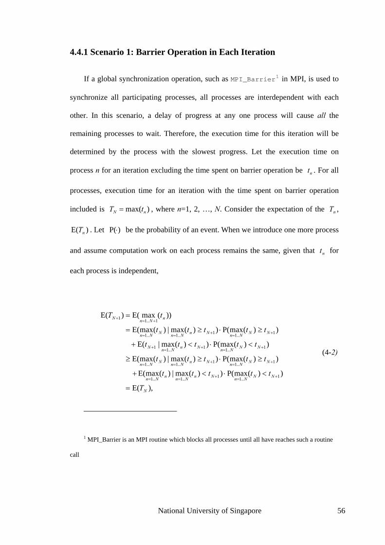
4.4.1 Scenario 1: Barrier Operation in Each Iteration
If a global synchronization operation, such as MPI_Barrier1 in MPI, is used to
synchronize all participating processes, all processes are interdependent with each
other. In this scenario, a delay of progress at any one process will cause all the
remaining processes to wait. Therefore, the execution time for this iteration will be
determined by the process with the slowest progress. Let the execution time on
process n for an iteration excluding the time spent on barrier operation be . For all
processes, execution time for an iteration with the time spent on barrier operation
included is , where n=1, 2, …, N. Consider the expectation of the ,
. Let
nt
)max( nN tT = nT
)E( nT )P(⋅ be the probability of an event. When we introduce one more process
and assume computation work on each process remains the same, given that for
each process is independent,
nt
),E(
))(maxP())(max|)(maxE(
))(maxP())(max|)(maxE(
))(maxP())(max|E(
))(maxP())(max|)(maxE(
))(maxE()E(
1..11..1..1
1..11..1..1
1..11..11
1..11..1..1
1..11
N
NNNnNnNnnNn
NNNnNnNnNNn
NNNnNnNnN
NNNnNnNnNNn
nNnN
T
ttttt
ttttt
ttttt
ttttt
tT
=
<⋅<+
≥⋅≥≥
<⋅<+
≥⋅≥=
=
+=+==
+=+==
+=+=+
+=+==
+=+
(4-2)
1 MPI_Barrier is an MPI routine which blocks all processes until all have reaches such a routine
call
National University of Singapore 56

where the equality holds if and only if 0))(maxP( 1..1=< += NnNn
tt , which is not true. This
means that when there is a barrier operation in each iteration and the computation
complexity in one iteration remains constant, the expectation of execution time for
one iteration will be increased if the number of processes is increased. Since the
computation does not get complex at any process, this increase in execution time can
be attributed to larger communication latency. In other words, when there is a barrier
operation in each iteration, the expectation of communication latency will be
increased. This conclusion about communication latency will no longer rely on the
assumption on constant computation on all processes, because communication latency
is independent with computation scale as long as the parallel processes are
homogeneous.
This conclusion can also be applied to scenario where barrier operation is not
present, but with the presence of an MPI_Reduce 2 operation followed by an
MPI_Bcast3 operation. The reduce operation causes the root process to wait until all
other processes have reached the same reduce operation, and the broadcast operation
causes all the non-root process to wait until the root process has reached the same
2 MPI_Reduce is an MPI routine which reduces (or collects) values on all processes to a single
value
3 MPI_Bcast is an MPI routine which broadcasts a message from a leading process (known as
root) to all processes in a process group (known as communicator)
National University of Singapore 57

broadcast operation. After the reduce operation, root process has the slowest progress.
So root process will be the last to reach broadcast operation, making all the non-root
process to wait for the root and then to continue from the broadcast operation
simultaneously. The overall effect is that progresses of all processes are now
synchronized. The two operations combined produce the same effect as a barrier
operation does, and thus the same conclusion can be applied.
4.4.2 Scenario 2: Process Communicating with only Neighboring
Processes in Each Iteration
Another common scenario is that at the end of each iteration, each process
communicates only with one or more fixed processes. The processes that one process
communicates with are called the neighboring processes. When spatial decomposition
is used for parallelism, which is the case of velocity-Verlet algorithm used for fiber
suspensions simulation, processes working on neighboring spatial subdomains will
usually need to communicate with each other and are neighboring processes.
Consider N processes in a line, with nth process communicates with the (n+1) th
and (n-1) th process where applicable. When a process reaches the communication
phase, it is synchronized with the 2 neighbors (1 if it is a boundary process). For
analysis, we define 3 time variables. For process n and iteration i, computation time
for this iteration is the time from the start of this iteration to the start of
communication phase within this iteration, and is denoted as ; starting from the
start of the first iteration, the elapsed time until the start of communication phase
within this iteration is denoted as , and elapsed time until the completion of
)(int
)(inτ
National University of Singapore 58

communication phase (which is also the completion point of this iteration) is denoted
as . The following relationship applies:
)(inT
),,max( 1)()(
1)(
)()1()(
in
in
in
in
in
in
in
T
tT
+−
−
=
+=
τττ
τ (4-3)
Figure 4-3 illustrates this relationship. The direct graph in Figure 4-4 can be used
to help calculate , or the completion time of iteration i at process n. This graph
grows downwards from top to bottom, with its edges representing the dependency
relationship. According to the above equations, each τ graph vertex depends on a T
graph vertex by adding a t value; each T depends on 2 or 3 τ vertices by selecting the
maximum value of these τ vertices. For example, depends on , , and
, and further depends on . From these recursive dependency relations,
it is easy to see that finally all can be represented by the sum of t as:
)(inT
)2(2T )2(
1τ)2(
2τ
)2(3τ
)2(3τ
)1(3T
)(inT
∑=
i
j
jj
t1
)(α , where j = 1, 2, …, i, and Nj ≤≤ α1 . (4-4)
National University of Singapore 59

Figure 4-3 Relationship between time variables defined for execution time analysis
Figure 4-4 Directed Graph illustrating calculation of execution time
National University of Singapore 60

This representation corresponds to a path in the graph. So the execution time of
the whole program,
)(max )(
..1
NiIi
TT=
∧
= , (4-5)
corresponds to a path P in the graph, and P is the optimal path to maximize ∧
T .
Now let us remove a process at the boundary and assume the computation on
other processes remains the same. If P has a vertex corresponding to the removed
process, this removal will change P, and reduce the overall execution time, because
the new P is non-optimal path in the original graph. If P does not have a vertex
corresponding to the removed process, then the execution time will not change
because P is still the optimal path. To summarize, removing a process will not change
the execution time or will reduce it; the expectation of the overall execution time will
be reduced by this removal, given that the possibility of the event that “P has a vertex
corresponding to the removed process” is not zero. Vice verse, introducing a new
process will increase the expectation of the overall execution time. Because the
computation at each process does not change, this increase in execution time can be
attributed to the increase in communication latency. In short, introducing more
processes into parallel computation will increase the expectation of communication
latency. Note that this conclusion does not require the assumption that the
computation remains constant on each process any more, because communication
latency is independent of computation scale as long as the parallel processes are
homogeneous.
National University of Singapore 61

In the above deduction, the process at boundary is chosen to be removed. This
choice is because we do not want to introduce new edges which will complicate the
problem. However, as we assume all processes are homogeneous, and for
different i and n are of the same distribution, the expectation of overall execution time
will only be related to the number of processes we use, and the conclusion drawn
above does not lose any generality despite the choice on process to be removed.
)(int
A simple MATLAB script is used to simulate this process. is assumed to
come from a normal distribution with a mean of 4 and a standard deviation of 1, and
does not change with the number of processes used. This means that the computation
scale at each process remains constant. Execution times of 10,000 steps are collected
with number of processes ranging from 2 to 8192. The simulation result, in Figure
4-5, shows that the overall execution time grows with the number of processes. This
is consistent with theoretical conclusion above.
)(int
National University of Singapore 62

Figure 4-5 Simulation result: execution time versus number of processes
From Figure 4-5, we also observe that with exponential increase in the number of
processes, the increase in execution time gets less and less significant. This is because
in the directed graph in Figure 4-4, with more processes, there will be smaller
possibility for the event that removing a boundary process will affect path P and thus
reduce the execution time. In other words, with more processes, adding another
process will generate less increase in the expectation of overall execution time. Rough
deduction shows that if increasing the number of processes from N to N×2
generates an increase in the expectation of execution time of t, then increasing the
number of processes from N×2 to N×4 will generate an increase in the
expectation of execution time of the amount 2t .
National University of Singapore 63

To summarize these two scenarios, when the computing processes are
homogeneous, which means the all computing processes have the same computing
capability and are assigned with computation task of relatively the same scale, the
expectation of communication latency will increase when more processes are used, if
processes use barrier operation to synchronize in each iteration, or if processes
communicate with some neighboring processes in each iteration.
4.4.3 Utility of Communication Overlap
Analysis above has shown that, when the overall problem scale is fixed, using
more processors and processes will increase the communication latency while
reducing the computation time at each process. Therefore, the communication latency
will quickly become the bottleneck of further performance improvement. When the
increase in communication latency is larger than decrease in computation time,
adding more processes will result in negative performance gain.
In the analysis in previous subsections, time spent on real data transfer is ignored,
and the communication latency considers only the wait time generated by
asynchronous progress among interdependent processes. Consequently, this
communication latency cannot be reduced by employing more advanced networking
technology. However, communication overlap technique can be used to reduce or
even fully hide the impact of this communication latency.
Here is the basic idea of hiding communication latency using communication
overlap. For time evolution style algorithms mentioned above in Section 4.1, 4.4.1
and 4.4.2, in iteration n of the main loop, there is computation that is not dependent
National University of Singapore 64

on interprocess communication happening at the end of iteration n-1; there is also
computation which the communication happening in iteration n does not depend on.
Computation belonging to these 2 types is later referred to as communication-
independent computation. Similarly, the computation that (probably indirectly)
depends on communication happening at the end of previous iteration and the
computation that is relied on by the communication happening in the same iteration
are referred to as communication-dependent computation. If the communication-
independent computation can be rescheduled to be carried out when the
communication in iteration n-1 or n is in progress, computation progress and
communication progress are overlapped. With this overlap of communication and
computation, these 2 program blocks are now executed in parallel rather than in
serial, and thus execution time can be shortened.
We now provide analysis on the utility of this technique. We will prove that this
technique will reduce the impact of communication latency in long-term running of
parallel program even though the main source of this latency, the progress
asynchronism among participating processes, is not changed. Similar to the above
analysis, communication latency brought by real data transfer is ignored. Consider the
two cases shown in Figure 4-6. In this figure, a parallel computation with two
participating processes, process 1 and process 2, is considered. Each rectangle
represents an iteration of a loop, with unshaded subarea representing communication-
dependent computation, and shaded subarea representing communication-independent
computation, which can overlap with communication in the previous iteration. During
the interprocess communication, when one process reaches communication phase
before the other one, without communication overlap it may initiates an idle wait for
the other one to start the communication, which is the solid subarea in the figure. A
National University of Singapore 65

running of 4 iterations is considered. In the first and the third iteration, the 2
participating processes have synchronous progress. In the second iteration, process 1
is delayed; and in the iteration 4, process 2 has a slower progress.
Figure 4-6 (A) non-overlap versus (B) overlap: comparison of latency
In case (A), in the second iteration, process 1 performs slower than process 2.
Therefore, no matter how fast process 2 is, it will has to wait for process 1 to finish
before it can do the communication and continue with the next iteration. It appears to
process 2 as large communication latency. The overall effect is that execution time of
process 2 for this iteration is lengthened. Later, in iteration 4, although process 1
finishes in a shorter time than process 2 does, similar communication latency will
now be applied to process 1 and process 1 cannot reclaim it previous delay in iteration
National University of Singapore 66

2. In summary, when no communication overlap is used, at any iteration, delay at
progress of one process will be reflected in all interdependent faster processes as
larger communication latency, and future faster progress at this very process cannot
reclaim this negative effect. Delays will get accumulated over iterations and will
increase overall execution time.
In case (B), the delay of process 1 in iteration 2 does not affect the progress of
process 2 because process 2 can continue with its communication-independent
computation of iteration 3 without finishing the communication of iteration 2. Later,
in iteration 4, process 1 has a faster per-iteration progress and its overall progress
catches up with normal progress. The overall effect is that its delay in iteration 2 is
reclaimed by its faster progress (like a negative delay) in iteration 4.
Comparing these 2 cases, the communication overlap technique prevents the
delay of progress of one process to affect other processes that interact with this
process; it allows the very process to effectively reclaim this delay in the future. In
our homogeneous system, the execution times of each iteration at different processes
vary around an average value. If the communication overlap technique is not used, a
delay, or a positive offset from this average value, will be immediately propagated to
neighboring processes and will hopefully affect the overall execution time, while a
faster progress, or a negative offset from this average value is hidden by propagation
from other neighboring processes. The overall effect is that communication latency
gets accumulated over iterations and increases total execution time. To the contrary, if
communication overlap is used, a delay will hopefully be reclaimed later by the same
process and will not affect the overall progress or the execution time. To summarize,
communication overlap technique is effective in reducing the impact of
National University of Singapore 67

communication latency brought by asynchronous progress of interdependent
processes.
4.5 Implementing the Parallel Fiber Suspensions
Simulation with Communication Overlap
4.5.1 Theoretical Aspects of Communication Overlap
We will now see quantitatively how much communication latency can be hidden.
It is possible to overlap communication with computation is because that if we ignore
the little CPU involvement in communication phase, communication and computation
basically use different types of resources and thus can happen simultaneously instead
of successively. (Using normal blocking communication procedures will let
communication and computation be executed consecutively.) As mentioned above, in
a typical iteration n of the main loop, there are two types of communication-
independent computation. Let the time spent of this computation be and time
spent on interprocess communication be . With communication overlap to let
these two blocks be executed in parallel, the execution time to finish them will be
as opposed to
compt
commt
),max( compcomm tt compcomm tt + when they are executed in sequence. It
can be seen that communication latency can be partially hidden (when )
or fully hidden (when
compcomm tt >
compcomm tt < ), and the overall execution time will always be
reduced.
National University of Singapore 68

The challenge of communication overlap technique is how to best reschedule the
algorithm to allow the overlap while at the same time preserving the validity of the
algorithm. This can be restated as the following scheduling problem: 1) scheduling as
much computation as possible to be executed when the communication is being
processed; and 2) changing the order of execution during rescheduling should not
break the data and control dependences among program blocks. The latter constraint
set by dependences usually limits the former. In fact, the existence of communication-
dependent computation can also be attributed to this constraint, because this
computation and communication has control and/or data dependences. Two methods
are used to obtain more opportunity for communication overlap: (A) break large
computation blocks which are communication-dependent into small ones, some of
which are communication-independent; and (B) conditionally break the data and
control dependences to generate more communication-dependent computation while
using variable rename and memory copy to preserve the accuracy.
The main loop is the level-1 program block. If we reschedule only inside this
level-1 block, most of the operations, which are treated as atomic elements during
scheduling, are communication-dependent and cannot be useful for communication
overlap. However, if we expand these operations in level-1 block to their
implementation, (in the programming language C, function calls are expanded to
function implementations,) then with finer-grain scheduling elements there are much
more opportunities for communication overlap.
Speculative execution is another technique used to generate more opportunities
for communication overlap. Speculative execution is the execution of code whose
result may not actually be needed, and is used to circumvent constraints set by control
National University of Singapore 69

dependence, for example, to reduce the cost of conditional branch instructions. In
such a case, before the condition is computed, which branch is to be executed is
unknown. Consequently, code inside the branches cannot be scheduled to be executed
prior to the condition gets known. Using speculative execution, one or more of the
branches are computed before the condition is available, with variable renames so that
speculative execution will not really change variables. Later when the condition gets
available, hopefully all or part of speculation execution result can be validated.
Speculative execution is useful in our rescheduling problem because there are
conditional branches. One important use is that the procedure
move_particles_to_neighbors is conditional, while the condition is
need_to_move computed from the global maximum velocity which requires
interprocess communication to compute. With speculative execution, some
computation of procedure move_particle_to_neighbors can be executed when
the interprocess communication is being processed.
Besides this control dependence, there are 3 types of data dependences, namely
flow data dependence, anti data dependence, and output data dependence. Both anti
and output data dependences can be circumvented via variable rename and memory
copy, while flow data dependence cannot be bypassed. An instruction is flow
dependent on instruction (or there exists flow data dependence from to )
when writes to a variable X which is later read by . is anti dependent on
instruction (or there exists anti data dependence from to ) when
reads from a variable X which is later written to by . is output dependent on
(or there exists output data dependence from to ) when writes to a
2S
1S 1S 2S
1S 2S 2S
1S 1S 2S 1S
2S 2S
1S 1S 2S 1S
National University of Singapore 70

variable X which is later written to by . Both dependences can be circumvented by
letting to write another variable X'; an instruction to copy X' to X is inserted at
the present location of . After this scheduling of will not be limited by this
dependence. This technique is used to reschedule some particle status update
computation to make it execute prior to the particle status is used to compute the
forces.
2S
2S
2S 2S
There is also the controversy of maximizing the communication-independent
computation blocks and preserving the clearness of algorithm. To best maximize the
communication-independent computation blocks, the rescheduling should happen at
the instruction or language primitive level. However, that would totally reshuffle the
program and leads to complete lose of clarity. Furthermore, the data dependence
analysis will be very complex. In fact, fine-grain will not necessarily generate
efficient algorithm, given that the rescheduling can only rely on approximation
algorithms. Our idea is that a non-optimal time saving in a big program block often
generates better result than a large time saving within many tiny program blocks does.
The method is that, we do a performance profiling to identify what the time-
consuming function calls are in the main loop. Based on the method (A) mentioned
above, the communication-dependent time-consuming function calls will be replaced
with its implementation and the generated “fat” main loop can have much more
communication-independent computation blocks. This is a 1-level expansion. If there
is still largely time-consuming function calls after expansion, a further expansion may
be done. We will not go any further to do another level of function call expansion,
which will largely worsen the clarity of algorithm.
National University of Singapore 71

4.5.2 Rescheduling
Our profiling program has helped us to identify critical function calls, which are
listed in the algorithm skeleton in Figure 4-2. Some important ones are
move_particles_to_neighbors, copy_particles_to_neighbors, and
velocity_Verlet. They are extended into their implementations, and the “fat” loop
body is listed in Figure 4-7.
Figure 4-7: Extended pseudo-code showing the structure of main loop
There are 2 communication blocks in one loop iteration in our simulation
program. The first one, later referred to as communication block 1, is to do particle
move and copy (procedure exchange_moved_particles and procedure
exchange_copied_particles), and another one, later referred to as
communication block 2 (procedure collect_GMV), is to collect the global maximum
velocity data. Both computation and communication access and share the same data,
which are the particle status information.
National University of Singapore 72
There exists control dependence from communication block 2 in iteration n-1 to
move_particles_to_neighbors in iteration n, because the global maximum
velocity (GMV) collected in procedure collect_GMV determines whether
move_particles_to_neighbors needs to be executed for the current iteration.
Some computation within move_particles_to_neighbors can be circumvented
from this dependence using speculative execution and is scheduled to be executed
simultaneously with communication block 2. In the final schedule in Figure 4-8,
prepare_to_move is speculatively executed and overlaps with communication block
2.
Anti data dependence exists from collect_GMV of iteration n-1 to
particle_status_update_1 of iteration n. This is because collect_GMV needs to
read the particle information, while particle_status_update_1 will write to
particle information. However, by letting particle_status_update_1 to output to
a backup memory location rather than normal memory storing particle status, it can be
overlapped with collect_GMV. Results in the backup memory can be copied back to
normal memory location at the original code position of collect_GMV.
Flow data dependence cannot be circumvented, but it largely limits scheduling in
our program. The most time-consuming computation, force_computation, is flow
data dependent on communication block 1. However, by looking into the
force_computation procedure, a large portion of the computation is not data
dependent on communication. The force_computation procedure computes forces
between all pairs of particles having distance within the cut radius. The particles
involved in this computation within one subdomain can be divided into 3 categories,
namely moved particles, which are moved from neighboring subdomain in the
National University of Singapore 73

previous move_particles_to_neighbors procedure, copied particles, whose
status is copied to the current subdomain by copy_particles_to_neighbors, and
normal particles, consisting of particles within this subdomain except for those moved
particles. Based on this categorization, the interactive forces among particles can be
divided into these 6 categories:
1. moved particles versus moved particles,
2. moved particles versus copied particles,
3. moved particles versus normal particles,
4. copied particles versus copied particles,
5. copied particles versus normal particles, and
6. normal particles versus normal particles.
Of these 6 categories, the last one involves only local particles and does not
require move_particles_to_neighbors to finish, and thus is not flow dependent
on communication block 1. Based on this, force_computation is divided into 2
parts. boundary_force_computation computes forces belonging to category 1 to
5, and non_boundary_force_computation computes forces belonging to category
6. The latter one, which accounts for most of the computation time, can overlap with
communication block 1 and can help reduce the impact of communication latency.
The final rescheduling result is shown in Figure 4-8.
non_boundary_force_computation overlaps with communication block 1, and
speculative particle_status_update_1, prepare_to_move, and
National University of Singapore 74

prepare_to_copy overlap with communication block 2. For speculative execution, a
complementary procedure is added to validate the result, and for prepare_to_move
which uses variable rename to avoid anti data dependence, a complementary
procedure is also added to copy the renamed results to original variables.
Figure 4-8 Rescheduling result
4.5.3 Implementation of Communication Overlap
Communication overlap is implemented by using asynchronous (or non-
blocking) communication primitive in many programming libraries. Unfortunately,
our experiments showed that non-blocking operations in MPICH with p4 device (or
MPICH-P4) cannot be used for this purpose. We observed that for message size
smaller than 128kB, they perform just like standard send and receive procedures and
do not return immediately, and for message size greater than 128kB, although they
National University of Singapore 75

return immediately, they do not perform the real data transfer until MPI_Wait4 is
called, which will block the program anyway. (Note that in the later case, the
conclusions in Section 2 still apply. It is like to move the communications down to
position of MPI_Wait.) In other words, the real data transfer always blocks the
execution thread and communication and computation cannot happen simultaneously.
This is probably because in MPICH-P4 non-blocking MPI operations are
implemented with synchronous socket communication, which means it is impossible
to make communication and computation happen simultaneously because they are in
a single execution thread.
We overlap communication with computation by letting them execute in a
separate OS thread. An extra thread is used to regulate computation when the
communication is blocking the main thread. At the beginning, the extra thread is
blocked in purpose. When the main thread is about to do communication and block,
the extra thread will be activated. Upon activated, the extra thread read a status set by
main thread, and pick the right computation procedures to start. When the main thread
is wakened upon the finish of communication, it checks for extra thread and waits for
its completion before it moves on. With careful synchronization between main thread
and extra thread, the communication and computation can be scheduled in an
overlapped manner. For secure multi-threading, we also move to MPICH2, all-new
implementation of MPI by MPICH developers, which has better thread-safe support.
Our new implementation based on the schedule above and on the multi-threaded
4 MPI_Wait is an MPI routine which blocks the process and waits for specified MPI send or
receive to complete.
National University of Singapore 76

MPICH2 has improved the performance on computer cluster. The next subsection
will list the experiment results.
4.6 Results
Using the experiment configured as listed in Section 4.3, tests are run on 1, 2, 4,
8 and 16 processors, with one process per processor. Wall clock time and CPU time
have both been recorded. For comparison purpose, the test is firstly conducted when
the system has zero load, and is then conducted when the system has a load of 1. The
UNIX program top is used to obtain the load information.
4.6.1 CPU Time
CPU Time is a good measurement of computation complexity. When different
numbers of processes are used, the overall computation complexity varies and this
will result in different CPU times. Table 4-2 shows the overall CPU times for
different numbers of processes with and without the communication overlap
technique applied. The overall CPU time is computed by adding up the CPU times of
the involved processors.
Table 4-2 CPU times with and without the communication overlap applied
Number of processes 1 2 3 4 5
Without overlap 53362s 50711s 49382s 50054s 54570s
With overlap 67914s 60409s 57221s 58129s 62519s
National University of Singapore 77
From Table 4-2, we see that in both experiments with and without overlap
applied, the overall CPU times first decrease and then subsequently increase. This is
the combined effect of 1) the decrease in complexity of non-optimal algorithms for
subproblems as the domain is divided into subdomains - an example of these
subproblems is to search for all particle pairs within a radius from a specific particle
in velocity-Verlet algorithm; and 2) the increase in the number of duplicated
computations of forces associated with particles positioning within a radius away
from the boundary of two neighboring subdomains. As the number of processes
increases beyond 4, the combined effect is the increase in overall CPU time because
the second factor dominates the first.
Table 4-2 also shows that even though the communication overlap technique
helps reduce the communication latency, the scheduling adds overhead and results in
larger CPU time. An example of overhead is the duplicated needed to separate one
program block (or procedure) into two blocks during rescheduling. In the subsequent
sections, we will evaluate the performance of applying the communication overlap
technique to zero-load system and non-zero load system.
4.6.2 Performance Evaluation using Zero-load System
We first test the program on a zero-load system. This means that our test
programs run exclusively on the system with no other programs to compete for the
resources, which is the case when the all parallel jobs are submitted to and controlled
by a central batch job scheduler. Similar to the CPU time test, only one process is
assigned to each processor. We note that due to the non-optimum of the parallel
velocity-Verlet algorithm, the computation complexity may decrease with the
National University of Singapore 78

increase in the number of processors. Therefore, conventional definition of speedup
and efficiency cannot be used. We define observed speedup ) and observed
efficiency as:
(NSo
)(NEo
%,100)()(
,processor with Ntimeexecution processor 1 with timeexecution )(
×=
=
NNSNE
NS
oo
o
(4-6)
and the plots of observed speedup and observed efficiency are shown in Figure 4-9.
From this figure, we see that 1) on zero-load system, using communication overlap
appears to degrade the observed speedup and observed efficiency and 2) as the
number of processes increases, the performance difference between experiment with
communication overlap technique applied and that without this technique gets
smaller. The overhead introduced by this technique, such as the thread
synchronization operations, accounts for the performance degradation. Furthermore,
because the system is of zero load, there is little asynchronism among the
participating parallel processes and thus small communication latency, leaving small
room for this technique to improve performance. However, as the number of
processes increases further, as discussed in the previous section, the communication
latency is not insignificant any more and the communication overlap technique starts
to take effect. This is why the observed efficiency of program having this technique
applied decreases slower. When 16 processes are used, program with this technique
and the program without this technique demonstrate comparable performances.
National University of Singapore 79

Figure 4-9 Observed speedup and observed efficiency on zero-load system
A separate test with 32 processes on 16 processors is performed 5 , and
performance of the program with the communication overlap technique applied
surpasses that of the program without this technique. This behavior demonstrates that
the communication overlap technique actually reduces the impact of communication
latency as the number of processes gets larger.
In a parallel implementation of an application, the efficiency generally reduces
due to the ineffective mapping and increase in communication among processes. In
our experiment, the observed efficiency can be larger than 100% because the overall
5 Because of limitation of usable processors in Hydra II, we could not run 32 processes on 32
processors, but rather 32 processes on 16 processors.
National University of Singapore 80

problem size (measured by CPU time) does not remain constant with different
numbers of processes. If we compensate the observed efficiency with change of
problem size, the new efficiency values will be below 100%. The original efficiency
and that after compensation are listed in Table 4-3. Compensation is calculated using
the following equation (with being the observed efficiency after
compensation):
)(NE p
program overlap-non process-1 of timeCPUprogram overlap-non process-N of timeCPU)()( ×= NENE op (4-7)
Table 4-3 Performance evaluation results: zero-load system
Number of processes 2 4 8 16 32
(on 16 processes)
Observed speedup when communication overlap is not
used 2.04 4.02 7.51 10.27 8.37
Observed speedup when communication overlap is
used 1.69 3.55 6.89 10.10 8.74
Observed efficiency when communication overlap is not
used 102% 100% 94% 64% N/A
Observed efficiency when communication overlap is
used 84% 89% 86% 63% N/A
Observed efficiency when communication overlap is not
used, after CPU Time compensation
97% 93% 88% 65% N/A
National University of Singapore 81

Observed efficiency when communication overlap is
used, after CPU Time compensation
80% 82% 81% 64% N/A
In summary, on zero-load system with no other users and with a single process
being assigned to each processor, the effect of applying the communication overlap
technique is minimal if not undesirable. This is primarily because of the insignificant
amount of communication latency. It is also observed that this technique started to
show some performance improvement as the number of processes gets larger such as
16 and beyond.
Such zero-load system is idealistic in system with interactive job submission
rather than with a global batch job scheduler, because many user processes share the
same computer cluster and their processes will actively look for resources. The
communication latency will be significant because of the much larger asynchronism
among participating parallel processes of a single job. In such a case, communication
overlap technique starts to play an important role. In the next section, performance
evaluation using non-zero load system is performed to model this scenario with
processes competing for resources.
4.6.3 Performance Evaluation using Non-zero Load System
Most of the time the simulation program cannot exclusively use a computer
cluster (except for system requiring job submission via a batch job scheduler, which
often means to wait for some time before the job can start). We now run the test on a
system whose nodes all have a load of 1, which means there is already another
National University of Singapore 82

program taking 100% of the CPU time and keeping the CPU 100% busy. We call this
process an interfering process. As each node of the computer cluster has to deal with
multiple computation-intensive operating system (OS) processes, the asynchronous
switches of OS processes will contribute to large asynchronism among parallel
computing processes. If the interfering process itself is not perfectly stable, it will
further contribute to the asynchronism among parallel computing processes. Large
degree of asychronism will bring large communication latency and therefore harm the
overall performance of the parallel program.
Figure 4-10 shows the observed speedup and observed efficiency of our parallel
simulation program under non-zero load situation. From this figure we see that only
in the 2-process case the experiment with communication overlap technique applied
shows worse performance than that without this technique. This is because the
overhead of communication overlap surpasses its benefits. For larger number of
processes, the communication latency becomes a main obstacle to high performance.
When more processes and processors are introduced, there is severe degradation of
efficiency, which limits further increase of performance by adding more processors.
Table 4-4 summarizes the results. When the number of processes increases from 8 to
16, observed speedup is improved by 65% (or from 7.16 to 11.85), compared to 93%
(or from 1.98 to 3.84) when the process number is increased from 2 to 4. The
communication overlap technique effectively tackles this problem and prevents the
severe decrease in efficiency as the number of processes increases. For example,
increasing the number of processes from 8 to 16 brings an improvement of 86% (from
7.79 to 14.50). In fact, if we take into account the effect of change in problem
complexity and uses speedup and efficiency compensation, the efficiency after
compensation almost remains constant with communication overlap technique
National University of Singapore 83
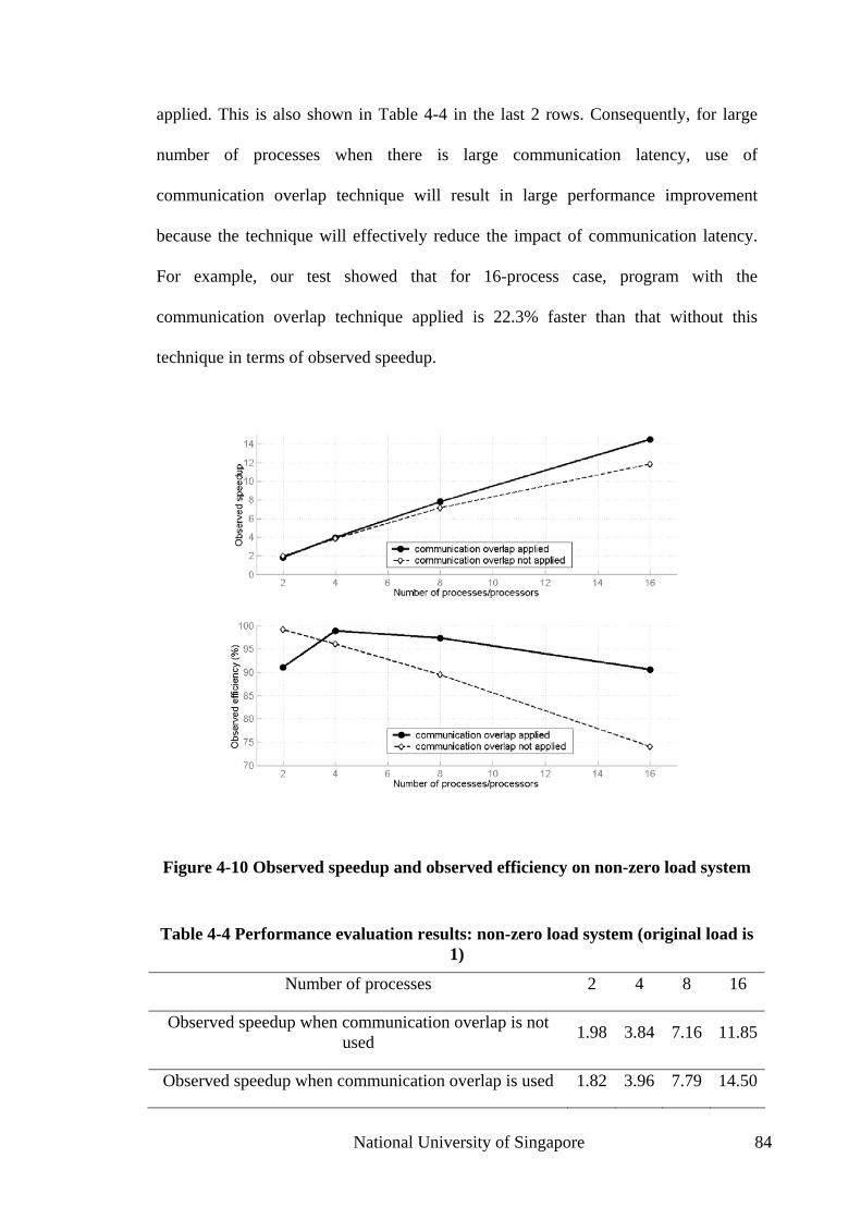
applied. This is also shown in Table 4-4 in the last 2 rows. Consequently, for large
number of processes when there is large communication latency, use of
communication overlap technique will result in large performance improvement
because the technique will effectively reduce the impact of communication latency.
For example, our test showed that for 16-process case, program with the
communication overlap technique applied is 22.3% faster than that without this
technique in terms of observed speedup.
Figure 4-10 Observed speedup and observed efficiency on non-zero load system
Table 4-4 Performance evaluation results: non-zero load system (original load is 1)
Number of processes 2 4 8 16
Observed speedup when communication overlap is not used 1.98 3.84 7.16 11.85
Observed speedup when communication overlap is used 1.82 3.96 7.79 14.50
National University of Singapore 84

Observed efficiency when communication overlap is not used 99% 96% 89% 74%
Observed efficiency when communication overlap is used 91% 99% 97% 91%
Observed efficiency when communication overlap is not used, after CPU time compensation 94% 89% 84% 75%
Observed efficiency when communication overlap is used, after CPU time compensation 86% 92% 91% 92%
In summary, the effectiveness of the communication overlap technique has
become significant when the communication latency is not trivial and especially when
the parallel machine has several active computation tasks. This is the case when the
number of processors involved in the computation is large and/or the computer cluster
is not dedicated to a single computation task. Communication overlap technique and
our implementation on MPICH2 have successfully reduced the impact of large
communication latency, and significantly improved the measurable performance. As
demonstrated in the case of 16 processes, introduction of this technique can increase
the efficiency as high as 22.3%.
4.7 Conclusion
A large number of computational bioengineering applications employ
decomposition to realize parallel computation. Fiber suspension simulation problem,
which utilizes spatial decomposition, is a typical example of these applications. A
vast majority of these applications suffer from degraded efficiency and even speedup
with the increase in the number of processors used, while actually they need more
processors to achieve faster computation. In this chapter, we use both experiment and
National University of Singapore 85

theoretical analysis to understand a major source of performance bottleneck:
asynchronism among participating parallel computing processes. This asynchronism
is an important source of communication latency, and the contributed latency grows
along with the number of processors. It therefore imposes an increasingly negative
impact on performance. Finally when the increase in communication latency brought
in by using more processors, together with other overhead, surpasses the benefit, the
limit of performance gain from parallel computing is reached.
We propose to use communication overlap technique to reduce the impact of
communication latency on performance, which is theoretically proved to be effective,
even for communication latency brought in by asynchronism among parallel
processes. Multi-threading is used to implement this technique, and block-level
rescheduling is performed to generate enough opportunities to allow communication
to overlap with computation. Experiments have shown significant improvement under
practical conditions on computer clusters. For example, in the experiment with 16
non-dedicated processors, our implementation increases the efficiency as high as
22.3%.
As mentioned above, the fiber suspension simulation problem belongs to a family
of similar computational bioengineering applications, and a vast majority of
applications in this family suffers from the same performance problem, especially
when the program is run on computer clusters. Our work helps to understand a major
source of performance bottleneck. We suggest incorporating communication overlap
technique into parallel programs for these applications, probably via the same
implementation as ours, to reduce the impact of communication latency and to
improve the overall parallel execution performance.
National University of Singapore 86

Chapter 5 Parallel Image Processing for Laser
Speckle Images
Laser speckle, a random interference effect that gives a grainy appearance to
objects illuminated by laser light, is widely used as a flow monitoring. It is used in
clinical applications as a non-contact, two-dimensional, full-field measurement of
retinal microcirculation. Laser Speckle Contrast Analysis (LASCA) is an important
technique in this application, which uses CCD camera for image capturing and
software digital image processing. When this is used for real-time clinical
applications, it imposes severe requirements on computing capacity. We propose to
use parallel computers for this task.
5.1 Introduction to Laser Speckle Imaging Technique
5.1.1 Laser Speckle Images
Laser speckle is a random interference effect that gives a grainy appearance to
objects illuminated by laser light. When a rough surface is illustrated by laser light,
light scattered from different parts of the surface within a resolution cell of the
detector (an eye or camera, for example) traverses different paths to reach the image
National University of Singapore 87
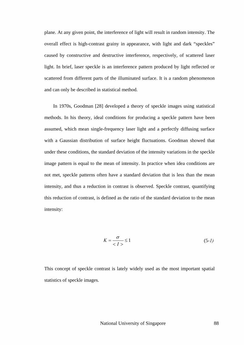
plane. At any given point, the interference of light will result in random intensity. The
overall effect is high-contrast grainy in appearance, with light and dark “speckles”
caused by constructive and destructive interference, respectively, of scattered laser
light. In brief, laser speckle is an interference pattern produced by light reflected or
scattered from different parts of the illuminated surface. It is a random phenomenon
and can only be described in statistical method.
In 1970s, Goodman [28] developed a theory of speckle images using statistical
methods. In his theory, ideal conditions for producing a speckle pattern have been
assumed, which mean single-frequency laser light and a perfectly diffusing surface
with a Gaussian distribution of surface height fluctuations. Goodman showed that
under these conditions, the standard deviation of the intensity variations in the speckle
image pattern is equal to the mean of intensity. In practice when idea conditions are
not met, speckle patterns often have a standard deviation that is less than the mean
intensity, and thus a reduction in contrast is observed. Speckle contrast, quantifying
this reduction of contrast, is defined as the ratio of the standard deviation to the mean
intensity:
1≤><
=I
K σ (5-1)
This concept of speckle contrast is lately widely used as the most important spatial
statistics of speckle images.
National University of Singapore 88

5.1.2 Time-varying Laser Speckle Image
When the illuminated object moves slowly as a whole solid object, the speckles
move with the object and remain correlated. When the object performs large motion
or when the object itself consists of individual moving scatterers (such as blood cells),
the speckles decorrelate and the speckle pattern fluctuates. This type of time-varying
speckle is frequently observed when biological samples are observed under laser light,
because of the flow of fluid inside biological components or even the motion of
particles within the cells. These fluctuations encode information about the velocity
distribution of the scatterers, such as the particles within the cells of biological
systems.
Several methods have been proposed to extract velocity information about the
particles from these fluctuations. These methods are whether based on time-integrated
speckle technique or time-differentiated speckle technique, both of which are
explained below.
The time-integrated speckle technique [29] treats acquired speckle image as
temporal integration of speckle fluctuations and uses spatial statistics to translate
acquired image pattern into velocity map. It is based on the fact that, in practice, it is
impossible to achieve instantaneous measurement of the speckle intensity due to the
finite integration time of the detector. Therefore, the obtained speckle image is always
integration of speckle fluctuations in the time domain. By measuring the depth of
modulation and/or integration time, estimation of particle velocity can be obtained.
Single-exposure speckle photography [30], as well as the derived Laser Speckle
Contrast Analysis (LASCA) [31] described in the Section 5.1.4, is based on time-
National University of Singapore 89

integrated technique and relates the spatial statistics (essentially the contrast) of the
time-integrated speckle pattern to the scatterer velocity.
A different approach is the time-differentiated speckle, which captures successive
speckle intensity images through continuous scanning and performs temporal
statistical analysis. Takai et al [32] used frequency analysis, while Fercher [33] used
speckle contrast and largely simplified the analysis. Ruth [34] [35] also used
differentiation of the speckle intensity and showed that the velocity is proportional to
the mean frequency of the fluctuations, and that this in turn is proportional to the root
mean square of the time-differentiated intensity.
5.1.3 Laser Speckle Imaging Systems
Using the techniques above, various Laser Speckle Imaging (LSI) systems have
been widely built and deployed in many engineering and especially medical
applications. One of the most important potential applications, first recognized by
Stern [36], aroused when the fluctuations were caused by the flow of blood; this
discovery was later developed into various non-contact and noninvasive blood flow
measurement techniques.
Early researchers used the temporal statistics of time-varying laser speckle. This
method can only measure the blood velocity at a point. When a map of blood velocity
distribution is required, either a mechanical scanning or the successive analysis of the
intensity fluctuations at different pixels in a CCD array is needed. The consequence is
large delay and non real-time operation.
National University of Singapore 90

Single-exposure speckle photography is a technique that removes the need for
scanning and offers a true full-field velocity map. It is essentially a photography
technique and uses an exposure time that is long enough to allow the faster fluctuating
speckles to blur out. The resulting photo is a time-integrated speckle pattern. It then
utilizes mathematical models to relate spatial statistics of this time-integrated speckle
pattern to the velocity of scatterers. This technique was successfully developed for
measurement of a retina blood flow [37].
The disadvantage of single-exposure speckle photography technique is that,
although it removes the need for scanning, it suffers from the disadvantage of being a
two-stage process that precludes real-time operation. This is because chemical
processing is required to develop the film before it can be used for spatial filtering.
5.1.4 Laser Speckle Contrast Analysis
Laser Speckle Contrast Analysis (LASCA) is a digital version of single-exposure
speckle photography. By replacing conventional camera with a CCD camera and a
frame grabber, the need for photographic stage is eliminated and facilitates digital
processing of the resulting photographs. Since the exposure is as short as 20
milliseconds, if the digital processing time is short enough, this technique can support
effectively real-time operation.
As shown in Figure 5-1, a LASCA LSI system basically consists of a laser light
source, a high-resolution CCD camera, a frame grabber, and a computer equipped
with specially developed software that computes the local speckle contrast and
converts it to a false-color map of contrast (and hence of velocity). The frame grabber
National University of Singapore 91

may also be a specialized software component built for the camera. It is important to
select a laser with suitable wavelength. For example, in a blood flow measurement
setting, laser wavelength should be selected based on the tissue under observation, as
it is necessary to achieve some tissue surface penetration with the laser light for blood
flow mapping.
Figure 5-1 Basic setup of LSI with LASCA
The sample, or area of interest, is illuminated with laser light while the computer
acquires a series of images at high speed with the frame grabber and CCD camera.
Each acquired image will display a slightly different speckle pattern, caused by the
change of position of moving scatterers in the area of interest. Every single frame
generated by the frame grabber is a time-integrated speckle pattern. Speckle patterns
are then sent to PC for statistical analysis. By assembling a series of frames, a real-
time video of velocity map can be achieved.
The principal of LASCA is similar to other time-integrated speckle techniques.
LASCA translates reduction of contrast to scatterers velocity. It is clear that the
higher are the scatterers velocities, the faster are the fluctuations of speckles and the
National University of Singapore 92

more blurring occurs in a given integrated time. It has been shown [30] that given
certain conditions, spatial statistics of time-integrated speckle patterns can be linked
to temporal statistics of the fluctuations in the following way:
∫=T
ts dCT
T0
2 )(1)( ττσ , (5-2)
where is spatial variance of the time-integrated speckle pattern, T is the
integration time, and
)(2 Tsσ
)(τtC is the autocovariance of the temporal functions at time t,
defined as
tt ItIItIC })({},)({)( −+−= ττ. (5-3)
It is now established that spatial statistics used in LASCA is equivalent to techniques
using temporal statistics so far as linking the measurements to actual velocities is
concerned. All techniques determine the correlation time cτ to estimate velocities,
and further assumptions are made to link speckle contrast to cτ . With assumption of
Lozentzian velocity distribution, it is shown that:
)1(2
2
c
Tc eT
K ττ −
−=.
(5-4)
National University of Singapore 93

This is further linked to mean velocity by
ccv
πτλ
2=
, (5-5)
where λ is the wavelength of the laser light.
It must be noted that it would be unwise to take too much account of the
quantitative value of the LASCA technique. The system being monitored is extremely
complex and there are many indeterminate factors in play. Most assumptions made in
the analysis are also inconsistent with practice. What is important from a medical
point of view is the ability to monitor the changes and variations. From this
perspective, LASCA technique is useful for medical applications. Besides, further
simplification will not harm the performance much.
5.1.5 Modified LSI
LASCA method uses speckle contrast to indirectly measure flow velocity. In
practice, to compute speckle contrast, a 5x5 or 7x7 region of pixels is used. Lower
numbers reduce the validity of the statistics, whereas higher numbers limit the spatial
resolution of the technique. The software computes the speckle contrast K for any
given square, and assigns this value to the central pixel of the square. The process is
then repeated for 5x5 or 7x7 squares centered on each pixel in turn. This results in a
National University of Singapore 94

smoothing of the contrast map, but the spatial resolution is lost in averaging over a
block of pixels. For example, when the image captured consists of 512×512 pixels
and a square of 7×7 is used to compute the spatial statistics for each pixel, the
resulting image will have resolution effectively reduced by use of this 7×7 squares to
73×73 (pixel blocks). Cheng et al. [38] realized this problem, and suggested a
modified LSI (mLSI) which uses temporally derived speckle contrast.
Temporal statistics of time-integrated speckle patterns was previously used to
obtain velocity information of a single point [29]. is defined as
tN
22
22
KI
IINt =><
><−><= , (5-6)
where <I> and >< 2I are the mean and mean-square values of time-integrated
speckle intensity variations during the time interval t. We can see that is
inversely proportional to the velocity of the scattering particle.
tN
Cheng extended this method to obtain a 2-D distribution of blood flow. In this
method, m frames are used to estimate the mean and mean-square values of time-
integrated speckle intensity variations. For the (i’th, j’th) pixel, its N is defined as
mt
I
IIN
ttji
ttjittjiji
..1
2
,,
2
,,2
,,,
=
−= , (5-7)
National University of Singapore 95

where is the instantaneous intensity of the i’th and j’th pixel at the t’th frame of
raw speckle images, and
tjiI ,,
tjiI ,, is the average intensity of the i’th and j’th pixel over
the consecutive m frames. The results are given as 2-D grey-scale or false-color coded
maps that describe the spatial variation of the velocity distribution in the area
examined. Both normalized velocity map and the speckle contrast map can be
computed thereafter.
5.2 Previous Work
Various implementations of digital image processing for LASCA and mLSI have
been built. When CCD cameras are used for imaging, the image processing procedure
becomes the only obstacle to achieve real-time operation.
Briers stated in his original paper about his LASCA implementation [30] that the
processing takes around 40 seconds, while the image capture takes only 20
microseconds. If the image processing time can be reduced to tens of microsecond’s
level, real-time operation is achieved. Although about 10 years has passed since
Briers’ initial work, the LASCA technique has not reached the real-time goal. In
Briers’ more recent paper [39], he described his improvements in the software that
reduce the processing time to one second.
Dunn et al. [40] have been using speckle contrast imaging to monitor cerebral
blood flow. They published their MATLAB scripts for computing speckle contrast on
the web. We have tested these short MATLAB scripts on a Pentium 4 2.4GHz
National University of Singapore 96

workstation with 256 MB of SDRAM. MATLAB profiler has shown that to generate
a speckle contrast image of 640x480, the scripts need 39 seconds to do spatial
statistics on 10 raw source images.
Researchers in our research group also implemented software for image
processing of mLSI speckle images [41]. To save computation time, binning is used
to preprocess the image so that less computation is required. Even with a binning size
of 2 to reduce the effective image size from 640x480 to 320x240, generating one
speckle contrast map using mLSI method will take this MATLAB program around 20
seconds.
Although it is possible to rewrite the whole program using more performance-
aware language such as C to approach real-time operation, that would make
programming much more difficult, especially with image processing program heavily
based on MATLAB image processing toolbox. There is also a trend of move to
higher-level and more user-friendly programming environment, to focus more on
programmability and to let system software and underlying hardware improvement
worry about the performance. Based on this consideration, we propose to leverage
parallel processing facility to approach real-time processing of speckle images. It will
not only reduce the processing time, but also support larger image with higher
resolution, given enough computing resources.
Speckle image processing is by nature suitable for parallel processing. Whether
spatial or temporal statistics is used, there is little dependence between two pixels that
are far enough from each other, and especially for temporal statistics every pixel is
independent of others. Parallelization requires segmentation of the image into several
blocks. When spatial statistics is used, each block will overlap with its neighboring
National University of Singapore 97

block; and when temporal statistics is used, blocks are disjoint. In both cases,
processing of different blocks is independent, and can be scheduled in parallel
without the need of interprocess communication. Based on the discussion in the
previous chapter, efficiency will not degrade with more processes (and processors)
and performance can be easily doubled by doubling the processes (and processors).
At the time of this writing, we have not found any implementation of parallel
processing system for laser speckle images. Although there is intensive research work
on parallel image processing and there are dedicated conferences on this topic, such
as Parallel and Distributed Methods for Image Processing, the research results
cannot be applied to laser speckle image processing. Most of the work focuses on
parallel algorithms for fine-grain parallel computing, usually based on a theoretical
model for algorithm research. A large portion of work relies on data parallelism, such
as [42] and [43]. Research on practical parallel image processing is usually based on
data parallelism with a special-purpose SIMD processor or VLSI circuit. A typical
example is Gealow et al’s work on pixel-parallel image processing [44], which is
based on large processor-per-pixel arrays. A very interesting and more relevant
research is the SKIPEER project [45]. In this research, parallel algorithms are
categorized into several general algorithmic skeletons. By describing the parallel
problems with a combination of supported skeletons and providing the sequential
functions, SKIPPER system is capable to generate efficient parallel program without
the programmer to deal with any detail of parallel execution.
When laser speckle image processing is considered, various algorithms used are
all relatively simple statistical analysis rather than complex conventional image
processing algorithms. The parallelization of these algorithms is relatively simple
National University of Singapore 98

decomposition and does not require complex programming framework or supporting
runtime. Computer cluster or network of workstations built from commodity
components is chosen as the hardware platform, and data parallelism is not usable.
Although SKIPPER is versatile and can support many types of applications, it is too
complex for our application.
The programming framework we propose for parallel laser speckle image
processing uses a simple master-worker paradigm. Because only laser speckle image
processing applications are supported, many logics will be built inside this framework
and programmers do not need to handle any parallel execution detail, and
performance will also be optimized for this specific application family. Our main
goals are customization of processing logic as well as portability to take advantage of
many different types of parallel computing resources.
5.3 Parallelism of mLSI Algorithm
Temporal statistics-based mLSI algorithm can easily be parallelized with spatial
decomposition. For a pixel on source images, the K value computed with mLSI is
only relevant to intensity value of this very pixel on several consecutive frames.
Because of this, when computing K value is considered, every pixel is independent
with the other pixels in the same frame. The extreme decomposition is to assign one
pixel to a processor, and none of the processors need to communication with others in
order to compute its corresponding K value. For load balancing purpose, with known
number of processors, decomposition of every frame will ensure processors receive
relatively the same amount of work load.
National University of Singapore 99

When general laser speckle image processing techniques using spatial statistics is
considered, the case is more complex. For every pixel in the image, its K value will
depend on several neighboring pixels. Because of this, when the image is segmented
into several blocks and has each block assigned to a processor, the processors have to
exchange pixel values at the segmentation boundaries. To avoid this interprocessor
communication, a simple approach is to send all necessary pixels when a block is sent
to a processor. In this way, the computation can be performed without the interaction
of the working processes. The same programming model as that for mLSI can then be
used.
5.4 Master‐worker Programming Paradigm
Master-worker paradigm is the main programming paradigm used in parallel
speckle image processing program. Master-worker approach is used for task that can
be partitioned into several independent subtasks, which can be carried out separately
and probably (but not necessarily) in parallel without any inter-subtask
communication.
National University of Singapore 100

Figure 5-2 Master-worker paradigm
The master-worker paradigm is depicted in Figure 5-2. The master node, usually
denoted as node 0, is in charge of farming out work load to workers. Several workers
work on work loads assigned by the master node. When a worker finished its current
work load, it reports the result back to the master if necessary and triggers the master
to send additional work load to the worker. As long as the task can be partitioned into
sufficiently small segments, this approach will produce small amounts of idle time for
the worker nodes.
Parallel speckle image processing is suitable for master-worker programming
paradigm. The master node serves as the feeding point of input image(s), and stores
the full speckle image or an array of frames of speckle images. It will segment each
image into blocks, based on the number of available workers. In conventional master-
work paradigm, subtasks will be maintained by master node in work load poll and
wait for a worker to pull them out for further processing. However, for speckle image
processing application, because of real-time requirement, indeterminism involved in
waiting for processing worker node is unaffordable for any image block. Instead each
National University of Singapore 101

block will be determinately assigned to a worker and this worker is expected to finish
this subtask in some specific time.
In order to support master-worker program, at least two types of services have to
be provided:
• Communication: Portions of computation and results must be passed between
master and workers;
• Resource management: System should manage the available computing nodes
and preferably their capabilities and loads, and support enquiry of status from
program.
Compared to communication, resource management of a master-worker
framework can be very complex. For example, it may support resource detection so
that master is capable of selecting the most appropriate subtask for the right worker
node; it may detect the interconnection scheme used by the computing nodes so that
the best routing method can be used to reduce communication latency. As a
demonstration work, our research focuses on testing the feasibility of real-time
processing with parallel computers, so resource management will be minimized. In
fact, a real-time application can hardly depend on an unstable and/or dynamic
platform such as that made available by Litzkow et al [17]. A stable environment with
static contributing machines, such as a computer cluster, may be a better choice.
When a computer cluster is used as the testing platform, the homogeneous
environment eliminates the necessity of many resource management functions,
because the load is automatically balanced and the worker nodes are static and
dedicated. Even if the framework is ported to a heterogeneous environment in the
National University of Singapore 102

future, when resource management becomes important, resource management
function should also be encapsulated and hidden from application coders. The result
is that any expansion to framework will be transparent to application coder and there
is no need to modify the application-level code. So the discussion here will not lose
any generality.
5.5 Implementation
5.5.1 High-level Architecture
For real-time performance and easy integration into existing medical devices, our
new implementation of speckle image processing system will be based on computer
cluster systems and Grid technology. The use of computer cluster is to utilize the
power of parallel computing to provide central, fast and stable processing of speckle
imaging data as well as to take advantage of the homogeneous environment to reduce
the system complexity. Since the data capture device is geographically separated from
the computing facilities, Grid technology is proposed to be used to integrate all
devices together. This also enables central processing of speckle imaging related data
for multiple capture devices so that multiple observations of blood flow can be taken
at the same time. The top-level system architecture is shown in Figure 5-3. This figure
shows that a central processing system is built on a computer cluster, which is
integrated with multiple image capture components using the Grid.
National University of Singapore 103

Figure 5-3 Illustration of top-level system architecture
At the beginning of a speckle image processing session, the workstation for
image capture will negotiate with the central image processing system through the
Grid. This negotiation will notify the central image processing system various
information about the image stream, such as compression method, frame size, and
frame rate. The central image processing system will then allocate enough resources
and prepare to work on the new image stream. Upon receiving further
acknowledgement from the image processing system, the image capture workstation
will start the image capture device and upload image stream to the image processing
system; it will also receive corresponding result image or video through the Grid.
When the last frame of image has been sent, the workstation will send an End-of-
Session command to the image processing system, which will perform post-session
work, such as freeing all allocated resource for this image stream and updating load
information.
National University of Singapore 104

Because the image capture components access the image processing service
through the Grid service portal, and does not rely on any information about how the
service is built, the image processing service can run on different platforms without
any modification to the image capture components. For example, the image
processing service can run at a single machine, with Grid service portal also built on
this machine; it may later be ported to a computer cluster, with Grid service portal
built on the head node which have access to the Grid, and which will further distribute
image processing subtasks to slave nodes of the same cluster. Image capture
components are unaware of this change and require no change in order to work with
the new system.
5.5.2 Master-worker framework implementation details
The image processing service is deployed on a computer cluster, and is built with
the master-worker paradigm described in Section 5.4. Figure 5-4 illustrates the
structure of the program. A master node gets the input image stream from the Grid
service portal. Known as the dispatcher, it will segment every image into several
blocks and send each to a worker node. The worker nodes receive the assigned image
blocks and apply image processing algorithms. The resulting image will be uploaded
to the assembler node, which assembles the output image stream and outputs the
result through the Grid service portal. When mLSI technique is used and temporal
statistics is based on M frames of input images, output frame rate will be reduced to
1/M of the input frame rate, which is shown in the figure.
National University of Singapore 105

Figure 5-4 Illustration of master-work structure of speckle image processing system
The system is designed with high-level of customization and portability in mind.
It allows the interface and image processing logic to be customized, and support
portability to various hardware types and communication libraries by rewriting a
small number of underlying communication functions.
Interface controls how the image processing system acquires input images and
outputs results. The core of the processing system, consisting of dispatcher, workers
and assembler, reads input stream from standard input and outputs to standard output,
which means that the interface to outside world can easily be built by wrapping and
redirecting the standard input and output. For example, the interface as a Grid service
portal is a program that reads input stream through the Grid and writes to the standard
input of the core; it also reads from the standard output of the core and writes back to
the Grid service consumer.
National University of Singapore 106
Considering the many methods, algorithms and parameters to determine in
speckle image processing, it is important to separate the processing logic from the
supporting code, which deals with initialization, communication, etc. There is also the
goal of making the processing logic code independent of the underlying
communication method, so that image processing service without any modification
can run on any underlying parallel machine which the framework has been ported to.
Based on these considerations, a framework called Abstract Communication Layer
(ACL) has been designed to separate the supporting code out and to serve as a simple
general master-worker application framework.
The architecture of ACL is illustrated in Figure 5-5. ACL has built in the main
program flow, which will deal with the execution details such as initializing the
underlying communication library, determining roles of computing nodes, reading
input image stream and outputting result images. The flow control code will call
image processing functions in custom logics for master node, worker nodes and
assembler node. The custom callback functions in these logics can utilize the master-
worker communication functions to handle information exchange between the master
and workers and between workers and the assembler.
National University of Singapore 107

Figure 5-5 Architecture of Abastract Communication Layer
The flow of the program is shown in Figure 5-6. A session is started after the
image capture components have successively finished the negotiation with the image
processing system. Based on the provided image stream information as well as the
underlying communication configuration, parameters and the environment are
initialized. Each computing node will then determine its own role, which is one of
master, worker, and assembler. Upon knowing its role, each node will switch to
perform its specific role function, which is also illustrated in Figure 5-6.
National University of Singapore 108

N
ational University of Singapore
109
Figure 5-6 Flowchart of the whole program, master node logic, worker node logic, and assembler node logic.

National University of Singapore 110
From the flowchart, it is seen that the custom image processing logic is
implemented in the following callback functions:
• Master init: This function is called on the master node at the beginning
of a session. It can be used to make necessary preparation, such as
allocating memory space and calculating parameters. Similar to this
function, worker nodes have Worker init and assembler node has
Assembler init.
• Master work: This function contains the main processing logic of master
node, and will be called for every input image or video frame. Normally,
this function implements the segmentation of input image and will call
ACL communication functions to feed the segments to worker nodes.
• Header parse: This function at master node is used to analyze header
information, which is attached before every image. The purpose of the
header is to provide extra information to the processing logic. For
example, the header may contain information about whether this is the
last frame. Parse extra command at worker node and that at assembler
nodes are for similar purposes; it will extract extra commands from the
image segment (for workers) or from the result segment (for the
assembler).
• Worker work: This function contains the main processing logic of master
node and will be called repeatedly until end of session command is
detected. Normally this function will read image segment through ACL

National University of Singapore 111
communication function and apply image processing algorithms to this
segment. When a result image is generated, it will upload the result to
assembler node using another ACL communication function.
• Assembler work: Similar to Worker work, this function will also be
called repeatedly. Normally it will read result image segments from all
worker nodes using ACL communication function. These segments will
be assembled and post-processed to generate the final resulting image,
which can be a K-map or a relative velocity false-color image.
Note that although the framework is written in C, the custom callback function
may not necessarily be written in C. Many programming languages provide
interfacing capability to C. For example, MATLAB contains a MATLAB Engine to
allow application to embed MATLAB as the computation engine; it also provides a
MEX file format to allow MATLAB code to call C functions. Using these two
techniques, bidirectional interfacing between framework in C and custom code in
MATLAB is accomplished. The framework will call custom code in MATLAB using
MATLAB Engine, and the custom code in MATLAB can call ACL communication
functions written in MEX file format.
From the above analysis it is clear that the communication between master node
and every worker node and that between every worker node and assembler node are
based on ACL communication functions. This design prevents the program from
being dependent on any specific underlying communication library and hardware. In

National University of Singapore 112
order to port to a new platform, only ACL communication functions need to be
rewritten. These include the following functions:
• acl_init: This is a callback function and will be called upon program
start-up. It can be used to initialize underlying communication system.
• acl_get_rank: This function returns a unique rank for each participating
computing node. This rank (or ID) can be used to perform role
determination.
• acl_get_no_of_processors: This function returns the total number of
participating computing nodes. This is also used for role determination.
• acl_feed_workers and acl_feed_workers_complement: These two
functions together accomplish the communication between the master
node and worker nodes. The former is called by the master node with a
data structure storing portions of data for each worker node. The latter is
called by the worker nodes to receive its portion of data.
• acl_query_workers and acl_query_workers_complement: These two
functions combined accomplish the communication between the
assembler node and worker nodes. The former is called by the assembler
to collect data from every worker node. The later is called by the slave to
submit data to the assembler.

National University of Singapore 113
• acl_stop_workers: This function provides a means for the master node
to terminate work at all worker nodes. Similarly, acl_stop_assembler
provides a means for a worker node to terminate work at assembler node.
• acl_finalize: A callback function that will be called upon the end of the
program. ACL can perform necessary resource reclamation work in this
function.
By leveraging the underlying communication library, such as MPICH or BSD
Socket, implementation of ACL is straightforward. We have finished two versions of
MPICH-based ACL implementations, one with data compression and another
without, within 350 lines of code. Some functions have their MPICH equivalents and
can be implemented by adding a function call wrap. For example, the MPICH
subroutine MPI_Comm_rank can be directly used for acl_get_rank, and
MPI_Comm_size, also in MPICH, can be used for acl_get_no_of_processors.
Other functions require more work but remain to be easy. For example,
acl_feed_workers is implemented by calling MPI_Send, the MPI subroutine to send
data from one process to another, for each worker node.
5.5.3 Special Considerations
1. acl_stop_workers and acl_stop_assembler
Most communication libraries do not provide primitives to terminate a remote
process. With MPICH, even if you terminate the node having rank 0, none of the

National University of Singapore 114
other node will exit because of the terminating node. In fact, the call to
MPI_Finalize will not return until all participating nodes call that function, which
means all nodes have to actively terminate themselves. So using MPICH,
acl_stop_workers and acl_stop_assembler can only implemented at a higher
level. For example, a dedicated channel for commands can be used; or a header can be
added to the beginning of each image segment being transferred.
To avoid overhead of adding the barely-used command channel,
acl_stop_workers and acl_stop_assembler are implemented by sending specially
designed faked image data which in fact contain a text message. The receivers will
not confuse it with normal images because of its abnormal size.
However, this implementation may not be used to terminate the remote processes
prematurely or asynchronously. In other words, when the remote processes are busy
processing normal images, it is impossible to stop them immediately, because the
terminating command is encoded also in an image, and will not be read until all prior
images have been successfully processed. To implement asynchronous terminating
command, a possible solution is to use another supervising process on each node,
which will monitor the status of the computing process and stop it upon receiving the
command. This is not implemented in our ACL implementation.
2. Concerns on Real-time Processing
Computing capacity and latency is an important issue in real-time applications.
Computing capacity concerns whether the CPU is fast enough to keep pace with the

National University of Singapore 115
input stream, and latency concerns whether the output comes too late after the
corresponding input frame.
Computing capacity is easier to be ensured. If the images come in at N fps, there
is 1/N second for processing at the master node, worker nodes and assembler node,
respectively. A typical value of N is 30. In this case, master node, worker nodes and
assembler node all have 33 milliseconds of processing time for one frame of image.
Normally that is enough time for speckle image processing, especially when the
image has been segmented and a sufficient number of processors have been used.
Communication overlap can be used to allow larger communication and
computation time. When the input image stream is at the frame rate of N fps, total
processing time of one image segment at the worker, including the time to receive the
image segment from the master and that to send the result image to the assembler,
should be kept below 1/N second. Otherwise, it exhibits as there is not enough
computing capacity to process image stream at that frame rate. When the
communication time is too large and leaves not enough time for image processing,
communication overlap technique introduced in the previous chapter can be used to
allow the communication and computation happen simultaneously, and thus roughly
1/N second can be spent on communication and computation, respectively.
Latency is relatively complex. From the Figure 5-4 it is seen that the image
processing system has a pipeline structure and increase in the pipeline depth will
imply larger latency. Fortunately, pipeline involved in this application has depth of
only 3. Suppose it takes for that data to travel from the image capture inputt

National University of Singapore 116
components to the image processing interface. Denote the time to dispatch it and pass
it to worker is . On receiving the block for this frame, the worker will generate
output false-color image. Denote the time for worker to process is . Denote the
time to pass it to the Assembler and the time to assemble is . Finally, suppose
it takes for the output to reach the visualization device. The total latency can
now be represented as:
dispatcht
kerwort
assemblet
outputt
outputassemblewordispatchinput tttttt ++++= ker . (5-8)
Of all the components in the above equation, and are not controlled by
the image processing system. Of the remaining three components, , compared
to the other two, is easier to control simply by using more processors and thus smaller
image segments. But and are relatively more significant, because
there are communication involved and the image data being transmitted is relatively
large. Even if more processors (and thus processes) are used, data involved in the
dispatching and assembling remains the same. The result is that, although there is no
bottleneck in the pipeline that leads to insufficient processing capacity, the image
stays for too long time in the pipeline and therefore the result image is output long
after the corresponding source image is inputted.
inputt outputt
kerwort
dispatcht assemblet
The solution is to communicate with compressed image data rather than with raw
data. Because compression is a computation-intensive task, algorithm should be

National University of Singapore 117
chosen carefully for this real-time application. LZO [46] compression library, a block
compression library that favors speed over compression ratio, is used for this task.
Specifically for mLSI which uses temporal statistics, the following solution may
be used. When M consecutive frames are used to compute one output image, for the
number 1 to number M-1 frame, they are processed normally as depicted in Figure
5-4. After the number M-1 frame is processed, all results are transmitted from workers
to the assembler. When the number M frame is available at the master, it is not
segmented and sent to workers; instead it is directly sent to assembler, which will
perform fast processing with some simplified algorithm. The final result image is
obtained by merging this result with those sent by workers and is soon available at the
output end. If the dispatcher and assembler reside on the same machine, there is extra
time saving by eliminating the need to do communication.
3. MPICH-specific Latency
When MPICH with p4 device is used to build the ACL, there is extra concern
about communication latency. Both master and assembler node perform point-to-
point communication with all workers. This is later referred to as 1-to-N
communication. Because MPICH communication is by default blocking, and for
master and assembler communicates with all workers one after another, a delay at any
worker may affect progress of other workers.
The master node will execute a send command for each worker when dispatching
the image segments. The series of send commands are issued one after another. For

National University of Singapore 118
large data package, a send command will not return until the data have really been
transmitted to the receiving end. In other words, the sequence in which the send
commands are issued is the sequence in which the real data transmission is
performed. Consequently, a delay at one worker, which is at the receiving end, will
possibly cause other workers which are later in the transmission sequence to wait for
an extra time. So it is importantly to keep the package size small so that send
command will return immediately without waiting for the data to be really
transmitted; or to use non-blocking send command so that the real data transmission
sequence will be independent of the sequence in which the send commands are
issued.
Similarly, the assembler node will execute a receive command for each worker
when assembling the result image segments. These series of receive commands are
also issued one after another. Whatever the data package size is, a receive command
will not return until the data is really received. So to prevent a delay at one worker to
affect others, it is important to use non-blocking receive command. Using this method
in this series of point-to-point communication operations, a point-to-point data
transfer will happen immediately when the two ends are ready, and will be
independent of the sequence in which the receive commands are issued. Therefore, a
delay at one worker will not affect progresses of the remaining workers.

National University of Singapore 119
5.6 Results and Evaluation
5.6.1 Study of MPICH Blocking and Non-blocking Operations
We first present our study on how the blocking and non-blocking operations of
MPICH are performed. The purpose of this experiment is to help determine the design
of 1-to-N communication at master node and assembler node.
1. Single Sender with Multiple Receivers
In this case, one sender node will send data to 2 receiver nodes, one after another,
with the first receiver delaying 1 second before receiving the data. Tests have been
done with different data package sizes and with the 1-second delay enabled and
disabled. Result is listed in Table 5-1.
Table 5-1 Time spent on blocking communication calls under different conditions
Data package size Description Value
Sender: first send time 0.117 ms
Sender: second send time 0.065 ms
Receiver 1: receive time (with 1 second of sleep time) 1004.4 ms
16k bytes
Receiver 2: receive time 2.6 ms
Sender: first send time 1015 ms 160k bytes
Sender: second send time 0.014 ms

National University of Singapore 120
Receiver 1: receive time (with 1 second of sleep time) 1017 ms
Receiver 2: receive time 1003 ms
From Table 5-1 it can be observed that: 1) when the package size is small, the
sender will not wait for the corresponding receiving acknowledge from the receiver,
therefore, although the first receiver delays for 1 second before receiving data, the
second receiver is not affected by this delay. This is because at this data package size,
MPICH will transmit the data to receiver even if it has not received a receiving
acknowledge from the receiver. 2) When the data package size is large, sender will
not return from sending subroutine before the receiver sends the receiving
acknowledgement. Consequently, when the first receiver delays for 1 second before
receiving data, the second receiver also has its progress delayed. This effect is
undesirable for the master node, when the delay at one worker will affect progresses
of many other workers.
Now replace the blocking send subroutines with its non-blocking counterparts
and redo the above experiments. After all non-blocking communication subroutines
have returned, an MPI_WaitAll is added to wait for real data transfer to finish. Times
spent on different communication subroutines are listed in Table 5-2.
Table 5-2 Time spent on non-blocking communication subroutines with different data package sizes and receiver response delay time
Data package size Description Value
16k bytes Sender: first send time 0.134 ms

National University of Singapore 121
Sender: second send time 0.066 ms
Sender: MPI_WaitAll 0
Receiver 1: receive time (with 1 second of sleep time)
1003.0 ms
Receiver 2: receive time 2.8 ms
Sender: first send time 0.026 ms
Sender: second send time 0.007 ms
Sender: MPI_WaitAll 1016.0ms
Receiver 1: receive time (with 1 second of sleep time)
1018 ms
160k bytes
Receiver 2: receive time 14.4 ms
From Table 5-2 it is seen that with both small and large data packages, the delay
at the first receiver will not affect the second receiver. Detailed analysis shows that 1)
at small data package size, the non-blocking send operation performs exactly the
same as its blocking counterpart; and 2) at large data package size, the non-blocking
send operation returns immediately after the data being transmitted have been copied
to the system buffer. This allows the second send command to be executed without
being postponed because of the delay in the first receive command.
This result suggests the use of non-blocking operations at the master node, if the
package size is large enough. MPICH source code uses 128k bytes as the minimum
size of large package.

National University of Singapore 122
2. Multiple Senders with 1 Receiver
In this case, 2 senders need to send data to a single receiver node, which uses a
loop to receive from these senders one after another. The first sender will delay for 1
second before it sends the data. When blocking receive is used, whatever the package
size is, the receiver will not return from the call to receiving subroutine until real data
transfer has been accomplished. This implies that receiving from the second sender
will definitively be delayed.
We directly test the non-blocking receive without validating property of the
blocking receive mentioned above. Similar to non-blocking send, an MPI_WaitAll is
added to wait for real data transfer to finish. Test result is listed in Table 5-3.
Table 5-3 Time spent on non-blocking communication calls under different conditions
Data package size Description Value
Receiver: first receive time 0.017 ms
Receiver: second receive time 0.002 ms
Sender 1: send time (with 1 second of sleep time) 1002.3 ms
16k bytes
Sender 2: send time 0.137 ms
Receiver: first receive time 0.018 ms
Receiver: second receive time 0.001 ms
Sender 1: send time (with 1 second of sleep time) 1015 ms
160k bytes
Sender 2: send time 12.3 ms

National University of Singapore 123
From Table 5-3, it is seen that with both small and large data package, non-
blocking receiving subroutine prevents the second sender to be affected by the delay
in the first sender. It is very important to use non-blocking receiving subroutine in
assembler, in order to prevent progress delay at one worker to affect other workers.
5.6.2 Experiment Settings and Results
Practical speckle image processing test has been performed. Testing speckle
image processing algorithm is based on Cheng’s mLSI [38]. All pixels in the images
are processed and 10 consecutive frames are used to generate 1 K map. Images
acquired by our colleagues [41] are used to test the program. These images are 696
pixels in width and 520 pixels in height. Every pixel is encoded in 4 bytes, one byte
for each of Red, Green and Blue components, and another byte for alpha channel.
These color images need to be converted into grey level images, which have intensity
encoded in 1 byte. However, to simulate images with higher resolution, these 4 bytes
are treated as independent intensity values and the effective pixel number is increased
by a factor of 3. In this way, the effective image size is 1392x1040 or 1,447,680
pixels.
Computer cluster mentioned in the previous chapter is used as the testing
platform. All image processing job is done at the worker nodes, without using
assembler node to compute the last frame of a group of 10 consecutive frames.
Communication and computation take place in sequence without communication

National University of Singapore 124
overlap technique applied. Based on this setting, time spent on processing every
frame of image is recorded and listed in Table 5-4.
Table 5-4 Time spent on processing 1 image frame when no compression is used
Setting Master node: Typical time
spent on processing 1 frame of image
Worker node: Typical time spent on processing 1 frame of
image
8 processors, no compression used 114 ms 114 ms
16 processors, no compression used 124 ms 124 ms
From Table 5-4 it is seen that when no compression used, both 8-processor and
16-processor setting cannot handle image processing at real-time at the input frame
rate of 33 fps. Detailed analysis shows that the bottleneck is at the master node: the
worker nodes spend less than 1 millisecond in computation task, because of the
relatively simple mLSI algorithm and the small size of image segment, more than 100
millisecond waiting for the master node to feed it with next frame of data, and another
around 10 millisecond in real data transfer from the master node. The master node
spends all time in transferring image segments to worker nodes, one after another and
one frame after another frame. To accomplish real-time processing, time spent on
transferring one frame of image segment must be reduced. Image data compression is
used for this purpose.
We now compare two candidate compression libraries, zlib [47] and LZO library
[46]. By assuming 10 worker nodes, image segment for each worker node will have

National University of Singapore 125
144768 pixels. 144768 bytes of data are used to test different compression methods.
The compression result and time using different compression library are listed in
Table 5-5. Note that the master node needs to repeat this compression procedure for
10 times for a single frame of input image.
Table 5-5 Comparison of different compression methods
Size before compression Compression method
Size after compression Compression time
zlib 10.2 Kbytes 21 ms
LZO 33.3 Kbytes 2 ms 144768 bytes
LZO 2-level compression 25.2 Kbytes 5 ms
From Table 5-5 it is seen that for this image size, machine configuration and
frame rate, only LZO compression library can be used to achieve real-time
processing. With smaller image size, LZO 2-level compression, which performs
another LZO compression on the result of a previous LZO compression, can also be
used. For zlib, although it generates desirable compression ratio, the compression is
large even for small image size, and can hardly be useful for our application.
With 1 level of LZO compression used, time spent on processing every frame of
image is largely reduced and the result is listed in Table 5-6. For both 8-processor and
16-processor settings, time spent on processing one frame of image at the master and
worker has fallen under the threshold of 33 milliseconds, and real-time processing is
achieved. Currently the processing time excluding time spent on data transmission is

National University of Singapore 126
less than 1 millisecond, including the small LZO decompression time, and there is
large room to employ better and more complex algorithms or to use higher
resolutions. When communication overlap is not used, using 8 processors will allow a
worker node to spend around 29 milliseconds in processing 1 frame of image
segment, and using 16 processors will allow around 10 milliseconds; when
communication overlap is used, both settings allow around 33 milliseconds of image
processing with higher image resolutions, if the little time involved in lzo
decompression is ignored.
Table 5-6 Time spent on processing 1 image frame when LZO compression is used
Setting Master node: Typical time
spent on processing 1 frame of image
Worker node: Typical time spent on processing 1 frame of
image
8 processors, LZO compression used 14 ms 14 ms
16 processors, LZO compression used 23 ms 23 ms
This result has shown that real-time processing is achieved using our framework.
The use of compressed communication channel allows more time to be spent on more
complex computation. If the communication overlap technique is used, there is even
more time for computation and the use of compression will allow more data to encode
the image. That is to say, the system will be able to handle images with higher
resolution.
National University of Singapore 127
5.7 Conclusion
In this chapter we have described our efforts in building real-time image
processing program on parallel platforms, including computer clusters. There is an
increasing need for parallel computing for image processing recently, especially in the
medical imaging area for the purpose of real-time processing. Laser speck image
processing is a typical example. However, research in parallel image processing
usually follows the data parallelism model and uses SIMD or special-purpose
platform. Little work is done to leverage the computing power of more accessible
computer clusters. We propose and implement a framework for parallel speckle image
processing to be run on computer cluster and other type of loosely-coupled
multicomputers. It is designed to be simple, utilizing the master-work paradigm. It is
also small, portable and scalable: porting the ACL to a new platform only requires
reimplementation of less than 10 functions, and the processing logic is separated from
underlying hardware platform and software environment. By allowing customization
of processing logic and custom code in other language such as MATLAB,
programmers can now easily change and extend the function using their favorite
languages and relevant libraries. We have studied the requirements of real-time
processing, and proposed to compress data using timing-friendly compression library.
Experiments have shown that real-time processing is achieved with our chosen image
processing algorithm, with further room to accommodate more complex algorithms. If
communication overlap is used, it is possible to use more complex algorithms and
larger number of processors, and be more tolerant to other overheads. In brief, our

National University of Singapore 128
design can be a desirable base to help developers easily build laser speckle processing
programs to run efficiently on many different types of parallel computers, to
maximally take advantage of the available computing power, and to achieve real-time
processing goals.

National University of Singapore 129
Chapter 6 Conclusions and Suggestions for Future
Work
6.1 Conclusions
Our research is motivated by the need to use computing power to address
computation problems in the emerging field of computational bioengineering. This
thesis mainly covers several techniques to facilitate use of computer clusters in
satisfying computing power for two representative bioengineering research issues.
Fiber suspension simulation is the first, which we choose as a representative for
the large number of computational biomechanics applications. These applications use
decomposition to exploit parallelism. Our research has pointed out that, for these
parallel programs, asynchronism among parallel processes of the same task is an
important source of communication latency, especially when they run on computer
clusters. We have proposed the use of communication overlap to eliminate impact of
communication latency. Our experience of implementing this technique in fiber
suspension simulation program is introduced. Realistic experiments on the new

National University of Singapore 130
simulation program have shown significant performance gain for both zero-load
system, such as computer clusters with a central batch job scheduler, and non-zero
load system, such as computer clusters with interactive job submission. For example,
in of our test with 16 parallel processes (and processors), program with the
communication overlap technique applied was 22.3% faster than that without this
technique in terms of observed speedup.
Real-time laser speckle image processing is the second issue, which we choose as
an example of many biomedical image processing problems having critical timing
requirements. We have found that although there is a lot of research work on parallel
image processing, little work is done on utilizing computer cluster for that task, when
computer cluster is actually the most accessible parallel computing facility nowadays.
Our research has focused on satisfying the timing requirements in real-time laser
speckle image processing. We aim at a simple, portable, and highly customizable
framework based on the master-worker programming paradigm. Performance
profiling shows that it is capable to process laser speckle images in real-time using
our chosen algorithm, there is much room to incorporate more complex algorithms.
Although our design is centered on the laser speckle image processing problem, the
design and the framework can be extended for use in many similar image processing
applications.

National University of Singapore 131
6.2 Areas for Improvement
There are a lot of areas that we can improve on based on our current research. As
for communication overlap technique, especially when it is applied to numerical
simulation problems similar to fiber suspension simulation, automation tools can be
built to perform high-level control flow rescheduling (Section 6.3). A programming
framework with built-in capability of communication overlap used in inter-process
communication is also an option (Section 6.4). As for master-worker framework for
parallel image processing, an implement of ACL using BSD Socket or WinSock can
largely extend the usable computing power in campus environment (Section 6.5).
Certain extensions to ACL to facilitate inclusion of MATLAB image processing
script can be very useful for bioengineering researchers who are more versed with
MATLAB and its powerful image processing toolbox (Section 6.6).
6.3 Automated Control Flow Rescheduling
Automated control flow rescheduling is to automatically reschedule the program
at block level to generate more opportunities for communication overlap. The
intensive research and great success in instruction scheduling of optimizing compilers
is a large impetus to work on automated control flow rescheduling. For high-level
control flow rescheduling, it is necessary to ask the programmer to provide necessary
information about every reschedulable code block (RCD), such as whether it is
communication-relevant or computation-relevant, what shared variables or arrays are

National University of Singapore 132
used and how they are used. To make it feasible, the programmer should also follow
some programming style, such as to distinguish global (or shared) variables from
local variables; they should choose appropriate the granularity of RCD.
The automation tools can build a dependency relationship among RCD from the
provided information about RCD. It may first perform a performance profiling
through a sample running. Acquired profiling data may help choose the important
RCD. If necessary, the user might be prompted to further decompose a RCD because
of its significant impact on the performance as well as the complex dependences it
involves. After that, dependence relationship graph will be built and rescheduling to
generate overlap of communication and computation will be carried out accordingly.
All the methods to circumvent data dependence restriction mentioned in Chapter 4
may be used.
Using existing research outcome in the area of instruction scheduling, building
the aforementioned automation tools may not face much technical challenge. Such
tools may largely promote the use of communication latency in parallel computing for
similar numerical simulation problems.

National University of Singapore 133
6.4 Programming Framework with Communication
Overlap
Communication overlap is very important for decomposition-based parallel
programs in computation biomechanics areas, and a framework to prebuild the
common details would largely ease the programming tasks. By implementing general
logics such as communication latency hiding in the framework, the programmers can
focus on writing application-specific code and let the framework writer to worry
about the common problems.
A lot of applications in bioengineering share the same features with fiber
suspensions simulations. These features include time-step approach, spatial
decomposition for parallelization, interprocess communication between neighboring
processes in every time step, and (optional) interprocess communication among all
processes in every time step. These applications can also share the same high-level
control flow but with several customizable application-specific functions.
The programming framework implements the general control flow, with
communication overlap applied. It leaves several application-specific functions to be
implemented by the users. The framework imposes very strict limitations on how the
user code use shared variables. Because the framework has internally used
communication overlap and control flow rescheduling, improper use of shared
variables will result in invalidation of rescheduling.

National University of Singapore 134
6.5 Socket‐based ACL Implementation
Considering the almost universal availability of BSD socket on all computer
platforms, building a socket-based ACL implementation will allow our ACL-based
framework to run on all computers. A Socket-based ACL will allow to take advantage
of a large number of high-performance workstations interconnected with high-speed
dedicated campus networks and to utilize these otherwise wasted computing
resources.
BSD Socket is built in all modern UNIX and Linux workstations and WinSock is
in available for every 32-bit Windows PC. With Socket-based ACL, master-worker
parallel program based on ACL will be able to utilize almost every workstation and
PC in campus as a computing node. Considering the excellent computer network that
keeps communication latency low and the large number of machines to choose from,
a temporary homogeneous cluster of workstations can always be built at any time. If
enough number of dynamic backup machines is also selected, exit of one or more
machines from this temporary cluster will not stop or affect progress of ongoing
computation.
It is noted that implementing such an ACL version requires a much more
complex resource management function. But the computing power it can generate
makes it a very interesting area to work on.

National University of Singapore 135
6.6 MATLAB extension to ACL
A MATLAB extension to ACL is to allow researchers to write ACL callback
functions in MATLAB. Considering the powerful image processing toolbox and a
comprehensive mathematical toolset, MATLAB is among the best choice for
researchers to try ideas and to write prototype implementations. For production use,
most researchers will choose to reimplement MATLAB functions using a more
performance-aware language, such as C or C++. However, as the computing power of
parallel computer makes slow language less a problem, and as MATLAB itself is
getting faster, there is less and less necessity to rewrite MATLAB functions. It is
important to support using MATLAB script as the custom logic in our ACL
architecture.
The MATLAB extension can allow bidirectional communication between
MATLAB and ACL – it will allow ACL to call MATLAB script as the callback
functions, and will allow MATLAB script to use ACL communication services.
MATLAB provides mechanism to implement both directions. When ACL needs to
call a MATLAB script, it can use the MATLAB engine feature. To expose the ACL
communication functions to MATLAB script, these functions can be rewritten to
follow the MEX file format. After the rewriting, MATLAB script can call these C
routines as MATLAB functions.
National University of Singapore 136
6.7 Summary
The use of parallel computers in bioengineering research and practice represents
a major step in development of bioengineering field. Techniques introduced in this
thesis are examples of this development of parallel computing in the subfield of
numerical simulations and image processing, with an emphasis of using computer
clusters as the supporting platform. Our techniques will benefit computational
bioengineering field by effectively powering more intensive simulation with higher
precision and better resolution and real-time high-density biomedical image
processing.

National University of Singapore 137
Bibliography
[1] Gordon Moore, “Cramming more components onto integrated circuits,”
Electronics Magazine, 19 April 1965.
[2] Herb Sutter, “The free lunch is over: a fundamental turn toward concurrency in
software, ” Dr. Dobb's Journal, Vol. 30(3), March 2005.
[3] Steven Fortune, and James Wyllie, “Parallelism in random access machines,” in
Proceedings of the tenth annual ACM symposium on Theory of computing, San
Diego, California, United States, pp. 114-118, 1978.
[4] V. S. Sunderam, “PVM: a framework for parallel distributed computing,”
Concurrency: Practice and Experience, Vol. 2(4), pp. 315-339, Dec. 1990.
[5] Michael J. Flynn, “Very high-speed computing systems,” in Proceedings of the
IEEE, Vol. 54, pp. 1901-1909, December 1966.
[6] Lou Baker, and Bradley J. Smith, Parallel Programming, New York, McGraw-
Hill, 1996.

National University of Singapore 138
[7] Donaldson V., “Parallel speedup in heterogeneous computing network,”
Journal of Parallel Distributed Computing, Vol. 21, 316-322, 1994
[8] Amdahl, G.M., “Validity of the single processor approach to achieving large
scale computer capability,” in Proceedings of AFIPS Spring Joint Computer
Conference, pp. 30, Atlantic City, New Jersey, United States, 1967.
[9] Gustafson, J. L., “Reevaluating Amdahl’s law,” Communications of ACM, Vol.
31(5), pp. 532-533, 1988.
[10] Yuan Shi. Reevaluating Amdahl’s law and Gustafson’s law. Available:
http://joda.cis.temple.edu/~shi/docs/amdahl/amdahl.html
[11] David Culler, J.P. Singh, and Anoop Gupta, Parallel Computer Architecture : A
Hardware/Software Approach, Morgan Kaufmann, 1998.
[12] Message Passing Interface Forum, MPI: A message-passing interface standard,
May 1994.
[13] A. Gara, M. A. Blumrich, D. Chen; G. L.-T. Chiu, P. Coteus, M. E. Giampapa,
R. A. Haring, P. Heidelberger, D. Hoenicke, G. V. Kopcsay, T. A. Liebsch, M.
Ohmacht, B. D. Steinmacher-Burow, T. Takken, and P. Vranas, “Overview
of the Blue Gene/L system architecture,” IBM Journal of Research and
Development, Special Issue on Blue Gene, Vol. 49(2/3), 2005.

National University of Singapore 139
[14] I. Foster, and C. Kesselman, The Grid: blueprint for a future computing
infrastructure, Morgan-Kaufmann, 1998.
[15] I. Foster, C. Kesselman, J. Nick, and S. Tuecke. The physiology of Gird: an
Open Grid Service Architecture for distributed system integration. Available:
http://www.globus.org/ogsa, June 2002.
[16] S. Tuecke, K. Czajkowski, I. Foster, J. Frey, S. Graham, C. Kesselman, T.
Maguire, T. Sandholm, P. Vanderbilt, and D. Snelling, “Open Grid Services
Infrastructure (OGSI) Version 1.0,” Global Grid Forum Draft Recommendation,
June 27 2003.
[17] Michael Litzkow, Miron Livny, and Matt Mutka, “Condor - a hunter of idle
workstations,” in Proceedings of the 8th International Conference of
Distributed Computing Systems, pp. 104-111, June 1988.
[18] Thomas E. Anderson, David E. Culler, and David A. Patterson, “A case for
Networks of Workstations: NOW,” IEEE Micro, February 1995.
[19] Alan M. Mainwaring, and David E. Culler. Active Messages: organization and
applications programming interface. Available:
http://now.cs.berkeley.edu/Papers/Papers/am-spec.ps, 1995.
[20] Jeff Bolz, Ian Farmer, Eitan Grinspun, and Peter Schroder, “Sparse matrix
solvers on the GPU: conjugate gradients and multigrid,” ACM Transactions on
Graphics, Vol. 22(3), 2003.

National University of Singapore 140
[21] P. Trancoso, and M. Charalambous, “Exploring graphics processor performance
for general purpose applications,” in Proceedings of the Eighth Euromicro
Conference on Digital System Design, 2005.
[22] W. Gropp, E. Lusk, N. Doss, and A. Skjellum, “A high-performance, portable
implementation of the MPI message passing interface standard,” Parallel
Computing, Vol. 22(6), pp. 789-828, September 1996.
[23] G. Almasi, C. Archer, J. G. Castanos, J. A. Gunnels, C. C. Erway, P.
Heidelberger, X. Martorell, J. E. Moreira, K. Pinnow, J. Ratterman, B. D.
Steinmacher-Burow, W. Gropp, and B. Toonen, “Design and implementation of
message-passing services for the Blue Gene/L supercomputer,” IBM Journal of
Research and Development, Special Issue on Blue Gene, Vol. 49(2/3), 2005.
[24] General-Purpose computation on GPUs. Available: http://www.gpgpu.org
[25] Randima Fernando, GPU Gems: programming techniques, tips, and tricks for
real-time graphics, Addison-Wesley, 2004.
[26] Ref H. P. J., and K. J. M. V. A., “Simulating microscopic hydrodynamic
phenomena with dissipative particle dynamics,” Enrophys. Lett., Vol. 19(3), pp.
155-160, 1992.
[27] R. Groot, P. Warren, “Dissipative article dynamics: bridging the gap between
atomic and mesoscopic simulation,” J. Chem. Phys., Vol. 107(11), pp. 4423-
4435, 1997.

National University of Singapore 141
[28] J. W. Goodman, “Some effects of target-induced scintillation on optical radar
performance,” Proceedings of IEEE, Vol. 53, pp. 1688-1700, 1965.
[29] A. F. Fercher, J. D. Briers, “Flow visualization by means of single-exposure
speckle photography,” Opt. Commun., Vol. 37, pp. 326-329, 1981.
[30] J. D. Briers, and Sian Webster, “Laser Speckle Contrast Analysis (LASCA): a
nonscanning, full-field technique for monitoring capillary blood flow,” J.
Biomedical Optics, Vol. 1(2), pp. 174-179, 1996.
[31] J. D. Briers, “Time-varying laser speckle for measuring motion and flow,” Proc.
SPIE, Vol. 4242, pp. 25-39, 2000.
[32] Takai N, Iwai T, Ushizaka T, and Asakura T, “Velocity measurement of the
diffuse object based on time differentiated speckle intensity fluctuations,” Opt.
Commun., Vol. 30, pp. 287–292., 1979.
[33] Fercher A. F., “Velocity measurement by first-order statistics of time-
differentiated laser speckles,” Opt. Commun., Vol. 33, pp. 129–135, 1980.
[34] Ruth B., “Superposition of two dynamic speckle patterns: an application to non-
contact blood flow measurements,” J. Mod. Opt., Vol. 34, pp. 257–273, 1987.
[35] Ruth B., “Non-contact blood flow determination using a laser speckle method,”
Opt. Laser Technol., Vol. 20, pp. 309–316, 1988.

National University of Singapore 142
[36] Stern M. D., “In vivo evaluation of microcirculation by coherent light
scattering,” Nature, Vol. 254, 56–58, 1975.
[37] J. D. Briers, and A. F. Fercher, “Retina blood-flow visualization by means of
laser speckle photography,” Inv. Ophthalmol. & Vis. Sci., Vol. 22, pp. 255-259,
1982.
[38] H Cheng, Q Luo, S Zeng, S Chen, J Cen, and H Gong, “Modified laser speckle
imaging method with improved spatial resolution,” Journal of Biomedical
Optics., Vol. 8(3), pp. 559-564, 2003.
[39] J. D. Briers, Xiao-Wei He, “Laser speckle contrast analysis (LASCA) for blood
flow visualization: improved image processing,” Proceedings of SPIE, Vol.
3252, pp. 26-33, June 1998.
[40] A.K. Dunn, H. Boaly, M.A. Moskowitz, and D.A. Boas, “Dynamic imaging of
cerebral blood flow using laser speckle,” Journal of Cerebral Blood Flow and
Metabolism, Vol. 21, pp. 195-201, 2001.
[41] Y K Tan, “Speckle image analysis of cortical blood flow and perfusion using
temporally derived contrast,” Final Year Project Report, National University of
Singapore, 2004.
[42] Frank J. Seinstra, Dennis Koelma, and Andrew D. Bagdanov, “Finite state
machine-based optimization of data parallel regular domain problems applied in

National University of Singapore 143
low-level image processing,” IEEE Transactions on Parallel and Distributed
Systems, Vol. 15(10), pp. 865-877, 2004.
[43] Thomas Braunl, Parallel Image Processing, Springers, 2001.
[44] Gealow, J.C., Herrmann, F.P. , Hsu L.T., and Sodini C.G., “System design for
pixel-parallel image processing,” IEEE Transactions on Very Large Scale
Integration (VLSI) Systems, Vol. 4(1), pp. 32-41, 1996.
[45] Jocelyn Serot, and Dominique Ginhac, “Skeletons for parallel image
processing: an overview of the SKIPPER project,” Parallel Computing, Vol.
28(10), pp. 1685-1708, 2002.
[46] M.F.X.J. Oberhumer. lzo compression library. Available: http://wildsau.idv.uni-
linz.ac.at/mfx/lzo.html
[47] Greg Roelofs. zlib compression library. Avaiable: http://www.zlib.net