para la instalación, manejo y mantenimiento de la …€¦ · la instalación de la máquina se...
TRANSCRIPT

Para la instalación, manejo y mantenimiento de la máquina es necesario leer minuciosamente las instrucciones It is absolutely necessary to read carefully the following instructions for the installation handling and maintenance of the machine Vor Inbetriebnahme ist es unbedingt erforderlich, die nachstehenden Bedienungsanleitungen eingehend zu studieren Il est absolutement necessaire de lire avec attention les instructions données pour l’installation, manoeuvre et entretien de la machine
Modelo/Model/Modell/Modèle
Nº de la máquina/Machine number/Maschinen-Nr/Nº de la machine
Potencia motor/Machine power/Motorleistung/Puissance moteur
Voltaje/Voltage/Spannung/Voltage
Fecha de verificación/Verification date/Abnahmedatum/Date de verification
CLIENTE/CUSTOMER/KUNDE/CLIENT
NOTA IMPORTANTE/ IMPORTANT NOTE/ WITCHIGE HINWEISE/ AVIS IMPORTANT
Para piezas de recambio es necesario señalar:/ It is necessary to state for spare parts: Für die entsprechenden Ersatzteile muss folgendes angegeben werden:/ Pour pièces de rechange il est necessaire de mentioner:
- Modelo de máquina/ Machine model/ Maschinenmodell/ Modèle de machine - Nº de máquina/ Machine number/ Machinen-Nr./ Numéro de machine - Nº de pieza/ Piece reference/ Ersatzteil-Nr./ Reference de la pièce
CONSTRUCCIONES MECANICAS ERLO, S.A. - P.O. BOX 19 - 20720 AZKOITIA (SPAIN)
Tel. (34) /943.851858 - Fax: (34) 943.85 71 28 E-mail: [email protected]
1
IMPORTANTE: Antes de hacer la instalación se deberá de leer detenidamente este libro de instrucciones.
PAUTAS A SEGUIR
• Manipulación y Transporte de la Máquina. • Puesta en servicio. • Utilización y reglaje. • Operaciones de Mantenimiento y Reparación más importantes.
DESCRIPCION DE DICHAS PAUTAS
• MANIPULACION Y TRANSPORTE DE LA MAQUINA.
La manipulación de la máquina desde el suelo al medio de transporte y desde el medio de transporte al suelo o a otro medio de transporte, se efectúa con grúas y elementos auxiliares de elevación, que deben tener capacidad de carga suficiente, incluyendo los coeficientes de seguridad reglamentarios, para manipular la carga con seguridad. En este mismo libro de instrucciones se indica como se tienen que hacer las operaciones de manipulación. (Ver hoja modo manipulación página 13).
• PUESTA EN SERVICIO.
La instalación de la máquina se efectuará en un local protegido de las inclemencias del tiempo y en lugar idóneo con relación al proceso productivo. El suelo tendrá la capacidad de carga suficiente para soportar el peso de la máquina, además tendrá la suficiente rigidez para soportar la máquina sin deformaciones inadmisibles que impidan el correcto funcionamiento de la misma, además se deberán impedir que las vibraciones generadas durante el trabajo de la máquina se transmitan al suelo o a la estructura del local. Deberá preverse una superficie suficiente para facilitar el trabajo de la máquina, la manipulación del material, el mantenimiento de la máquina y el paso del personal. Para la puesta en servicio de la máquina, se deberá tener en cuenta lo siguiente: • El personal que efectúe los trabajos de puesta en servicio debe estar adecuadamente formado y utilizar en
caso necesario las prendas de protección y las herramientas adecuadas en aquellos trabajos que tenga que efectuar bajo tensión.
• La superficie mínima necesaria con ó sin mesas auxiliares que se requiere para que pueda desarrollarse correctamente el trabajo de la máquina y se pueda efectuar el mantenimiento y la reparación de forma fácil y segura.
• Los datos de anclaje y de los sistemas antivibratorios que requiere (página 9). • La tensión de alimentación. • Asegurarse que la corriente que se va a utilizar, coincide con el voltaje del taladro. • En las máquinas de conexión trifásica se han de conectar los cables a las bornas TIERRA, RST y N, si
necesitara (N = Neutro). • Atención, tener especial cuidado de comprobar el sentido de giro del eje principal, antes de poner
en funcionamiento el sistema de Roscado con Husillo Patrón (Equipamiento Extra). • Comprobar que el sentido de giro del eje principal y de la bomba de refrigeración es el correcto según
indica la placa de mandos. • En las máquinas suministradas con equipos tanto neumáticos como hidráulicos, regular el caudal de aire y
presión mínima necesaria según indica el libro de instrucciones.
• UTILIZACION Y REGLAJE
1. COLOCACIÓN DE LA HERRAMIENTA.
Asegurarse siempre que la máquina está parada. Se sujeta con la mano derecha el mando de bajada del eje y con la mano izquierda se introduce en el cono del eje la herramienta mediante un golpe seco, teniendo en cuenta que la lengüeta de la herramienta y el alojamiento del eje para dicha lengüeta estén en la posición correcta. Deberá también tenerse en cuenta en las máquinas que lleven expulsor automático de brocas, tanto al introducir la herramienta como al estar la máquina trabajando en automático o en manual el seguro del expulsor, deberá estar introducido en la parte interior o en la posición "B". S/dibujo adjunto nº 2 (página 4).
2
2. EXPULSOR AUTOMÁTICO DE LA HERRAMIENTA. (Excepto en máquinas equipadas con husillo patrón).
Tirar del mando nº 3 (página 4) hacia el exterior. Sujetar con la mano izquierda la herramienta y con la mano derecha dar un golpe seco en sentido horario con el mando nº 2 en la parte superior del eje principal s/dibujo nº 2 (página 4). Advertencia: Es importante que el mando nº 3 (página 4), esté siempre en la posición “B” para las operaciones de trabajo. Antes de efectuar esta operación, pulsar el Stop de emergencia y asegurarse que el eje principal está completamente parado.
3. REGULACIÓN DE LA ALTURA DE LA MESA.
Desbloquear los mandos de blocaje nº 14 (página 9) del soporte de la mesa y con el mando de desplazamiento vertical del soporte mesa nº 28 (página 9), regular la altura de la mesa. Bloquear de nuevo los mandos de blocaje nº 14 (página 9) del soporte de la mesa.
4. REGULACIÓN DE LA INCLINACIÓN DEL SOPORTE DE LA MESA.
Aflojar las tuercas nº 13 (página 9) y regular la inclinación del brazo giratorio según los grados necesarios e indicados en la regla graduada nº 11 (página 9) del soporte. Una vez terminada la regulación, volver a apretar las tuercas de blocaje nº 13 (página 9).
5. REGULACIÓN DEL GIRO DE LA MESA.
Desbloquear el mando de blocaje nº 12 (página 9) del soporte y regular el giro de la mesa. Bloquear de nuevo el mando de blocaje nº 12 (página 9) del soporte. Advertencia: Asegurarse de que durante los procesos de trabajo los mandos y tornillos de blocaje estén bloqueados.
6. CAMBIO DE VELOCIDADES.
Los mandos señalados con el nº 3 (página 9) son los que se utilizan para cambiar las velocidades. Las diferentes velocidades se indican en la placa nº 5 situada junto a estos mandos. Es importante que antes de hacer un cambio de velocidades se asegure que el eje está completamente parado para no dañar los engranes de transmisión.
7. PROFUNDIDAD DE TALADRADO.
Para regular la profundidad de taladrado, aflojar el tornillo de blocaje nº 8 (página 9) y girar el tornillo moleteado nº 9 (página 9) en un sentido u otro. El índice de profundidad nº 18 (página 9) nos indicará en mm. o en pulgadas, la profundidad de taladrado. Una vez terminada la regulación, volver a apretar el tornillo de blocaje nº 8 (página 9).
8. AVANCE MANUAL SENSITIVO FINO.
Para conectar el avance manual sensitivo fino, desplazar hacia arriba el volante nº 7 (página 9). Para desconectar el avance manual sensitivo fino, desplazar hacia abajo la palanca nº 19 (página 9).
9. ROSCADOR HUSILLO PATRÓN (Equipamiento extra).
Tanto el conjunto como el sistema de funcionamiento del Roscador Husillo Patrón, se halla especificado en la página 14.
10. ROSCADOR SENSITIVO (Equipamiento extra).
Tanto el conjunto como el sistema de funcionamiento del Roscador Sensitivo, se halla especificado en la página 14.
11. INVERSIÓN DE ROSCADO (Equipamiento extra).
Tanto el conjunto como el sistema de funcionamiento de Inversión de Roscado, se halla especificado en la página 14.
• AVERIAS MÁS COMUNES
• ROTURA DEL MUELLE DE RECUPERACIÓN.
3
Quitar la tapa de protección y extraer el muelle para la reposición, colocar el extremo central del muelle en la ranura del eje y sujetando el otro extremo del muelle con una mordaza Grip, hacerla girar en sentido antihorario hasta conseguir la tensión adecuada, una vez esto, introducir el tornillo en el alojamiento de sujeción del muelle. s/dibujo adjunto nº 1 (página 4)
• MANTENIMIENTO
Los trabajos de mantenimiento consisten en el engrase manual o semiautomático de los diferentes mecanismos, la forma de efectuarlos y la periodicidad de las mismas está indicado en este libro de instrucciones (página 5 y 6).
• OPERACIONES QUE PUEDAN OCASIONAR ALGÚN NIVEL DE RIESGO.
TALADRADO.
• Todas las piezas a mecanizar como los elementos de sujeción deberán estar siempre bien amarrados a la mesa de trabajo.
• Todos los mandos de sujeción de soporte, mesa y columna deberán estar siempre bien bloqueados. • Se deberán tener en cuenta siempre todas las placas indicadoras de peligro. • El mando del dispositivo del expulsor automático de la herramienta deberá estar siempre en la posición
"B", s/dibujo nº 2 (página 4). • Se deberá tener siempre en cuenta, tanto trabajando en avance manual como en automático, los posibles
golpes que pueda ocasionar el mando nº 6 (página 7) debido a la energía elástica del muelle de recuperación del eje principal.
REPARACIÓN Y MANTENIMIENTO.
Todas las operaciones de reparación y mantenimiento, han de realizarse por personal capacitado y tomando las medidas de seguridad pertinentes.
• DEPOSITO DE REFRIGERANTE
La base del taladro se utiliza como depósito de refrigerante, que tiene una capacidad de: TC-25 7 lt. TC-30 7 lt. TC-32 10 lt. TC-35 10 lt.
TC-32 1
IMPORTANT: Before starting with the installation, you should read this operation handbook carefully.
STEPS TO FOLLOW
• Machine handling and transport • Machine start-up. • Operation and adjustment. • Most important maintenance and repairs operations.
DESCRIPTION OF THE ABOVE STEPS
• MACHINE HANDLING AND TRANSPORT
Machine handling from floor-transport-floor or another transport, is carried out with suitable cranes and lifting auxiliary items, which must assure enough loading capacity to lift the load safely.
This handbook also shows how the handling operations must be performed (see page 17).
• MACHINE START-UP.
The machine should be installed in a place, which is protected against inclement weather. The foundation should have enough capacity to support the weight of the machine and it should also be tough enough to support the machine without inadmissible deformations, which prevent the correct function of the machine. Besides you should avoid the transmission of any vibration to the floor or structure of the place.
You should provide enough room around the machine to ease the operation, handling of materials, machine maintenance and staff safety.
Before the start up of the machine, please note the following:
• Skilled workers, equipped with the correct clothing and tools should carry out the start-up. • Make sure that the machine has enough space with or without auxiliary tables to allow and ease
the safe, working, maintenance and repair operations. • Ensure that the machine foundation and vibration proof system is adequate (page 9) • Check the supply voltage. • Make sure that the current to be used is the same as the drilling voltage. • The main switch nº1 (page 4) is installed in the electric cabinet, as per drawing nº3 (page 4). - On
machines with three phase connection, the connection should be EARTH, RST and if required N (N= Neutral).
• Before checking the turning sense, make sure that the automatic feed command and/or the sensitive feed are disconnected. See point 7 (page 2).
• Test that the main spindle and the coolant pump (if it has) is running in the correct direction, as per indicated on the command plate.
• In the machines supplied with pneumatic or hydraulic equipment, regulate the rate of airflow and the required minimum pressure as per the operation handbook.
• OPERATION AND ADJUSTMENT
1. TOOL SETTING
Always make sure that the machine is stopped. Grip the spindle downward command with the right hand and with the left-hand insert the tool into the spindle taper with a dead blow. Take into account that the tool releasing tongue and the shaft housing are in the correct position. As per drawing nº2 (page 4)
2. TABLE HEIGHT ADJUSTMENT AND SUPPORT UNIT TURNING
Unlock the locking command nº10 (page 9) of the support and with vertical displacement command of the support nº14 (page 9), adjust the table height. Lock again the locking command nº10 (page 9) of the support.
3. TABLE SUPPORT INCLINATION ADJUSTMENT
TC-32 2
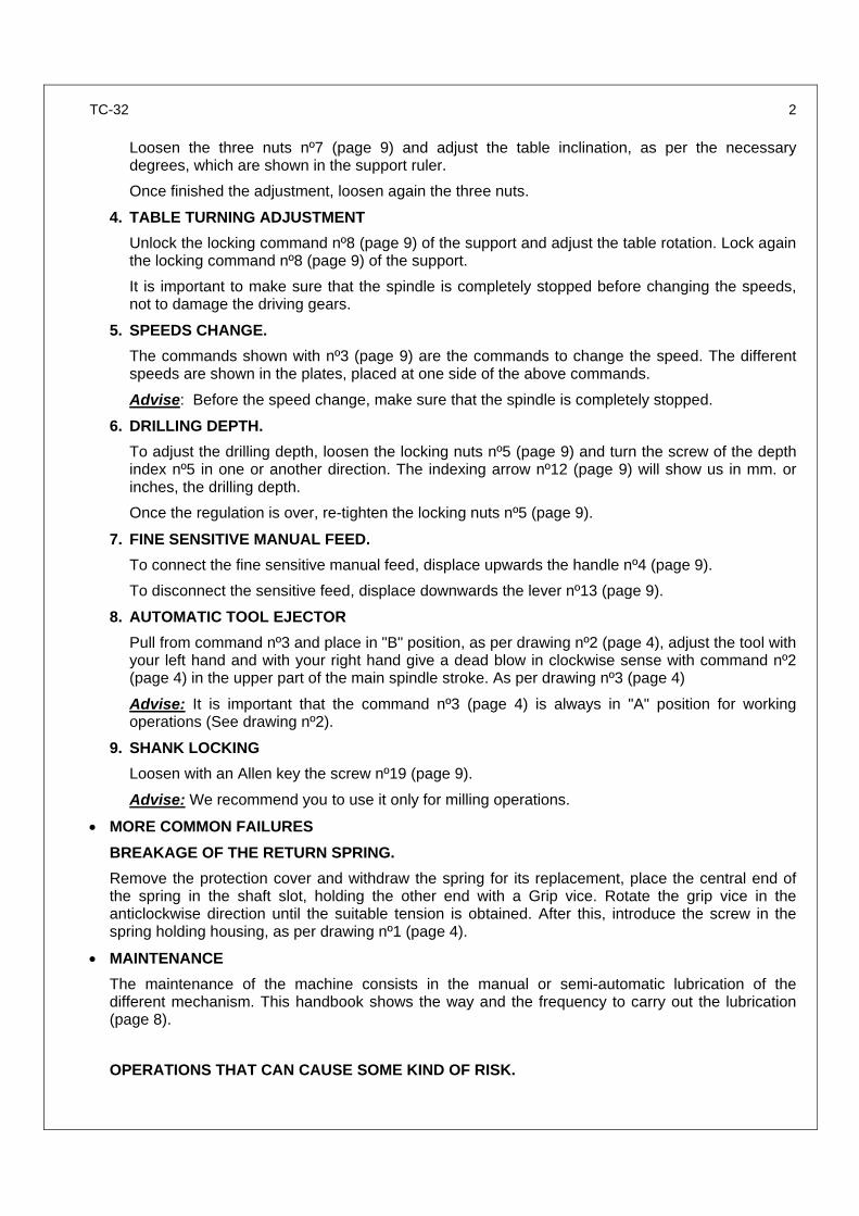
Loosen the three nuts nº7 (page 9) and adjust the table inclination, as per the necessary degrees, which are shown in the support ruler.
Once finished the adjustment, loosen again the three nuts.
4. TABLE TURNING ADJUSTMENT
Unlock the locking command nº8 (page 9) of the support and adjust the table rotation. Lock again the locking command nº8 (page 9) of the support.
It is important to make sure that the spindle is completely stopped before changing the speeds, not to damage the driving gears.
5. SPEEDS CHANGE.
The commands shown with nº3 (page 9) are the commands to change the speed. The different speeds are shown in the plates, placed at one side of the above commands.
Advise: Before the speed change, make sure that the spindle is completely stopped.
6. DRILLING DEPTH.
To adjust the drilling depth, loosen the locking nuts nº5 (page 9) and turn the screw of the depth index nº5 in one or another direction. The indexing arrow nº12 (page 9) will show us in mm. or inches, the drilling depth.
Once the regulation is over, re-tighten the locking nuts nº5 (page 9).
7. FINE SENSITIVE MANUAL FEED.
To connect the fine sensitive manual feed, displace upwards the handle nº4 (page 9).
To disconnect the sensitive feed, displace downwards the lever nº13 (page 9).
8. AUTOMATIC TOOL EJECTOR
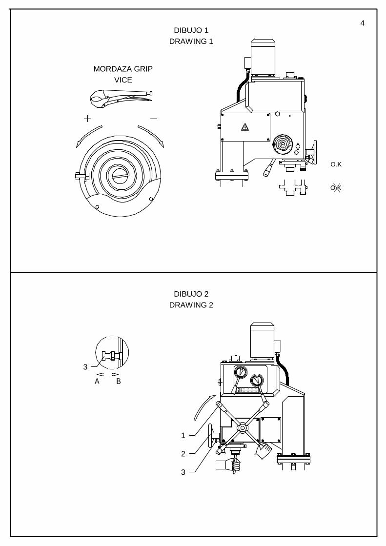
Pull from command nº3 and place in "B" position, as per drawing nº2 (page 4), adjust the tool with your left hand and with your right hand give a dead blow in clockwise sense with command nº2 (page 4) in the upper part of the main spindle stroke. As per drawing nº3 (page 4)
Advise: It is important that the command nº3 (page 4) is always in "A" position for working operations (See drawing nº2).
9. SHANK LOCKING
Loosen with an Allen key the screw nº19 (page 9).
Advise: We recommend you to use it only for milling operations.
• MORE COMMON FAILURES
BREAKAGE OF THE RETURN SPRING.
Remove the protection cover and withdraw the spring for its replacement, place the central end of the spring in the shaft slot, holding the other end with a Grip vice. Rotate the grip vice in the anticlockwise direction until the suitable tension is obtained. After this, introduce the screw in the spring holding housing, as per drawing nº1 (page 4).
• MAINTENANCE
The maintenance of the machine consists in the manual or semi-automatic lubrication of the different mechanism. This handbook shows the way and the frequency to carry out the lubrication (page 8).
OPERATIONS THAT CAN CAUSE SOME KIND OF RISK.
TC-32 3
DRILLING.
• All the pieces to be machined as well as the holding items should always be well secured to the working table.
• All the support, table and column locking commands should always is well locked. • The danger indicating plates should always be taken into account. • The command of the automatic tool ejector device should always be in "A" position as per
drawing nº • 2 and 3 (page 4) • Do not work in automatic feed, while command nº3 is in "B" position, as per nº2 and 3 (page 4). • Take special care, while working in manual or automatic feed, with command nº9 (page 9) when
it returns, due to the elastic energy of the return spring of the main spindle.
REPAIR AND MAINTENANCE
All the repair and maintenance operations, must be carried out by skilled staff and taking the necessary safety measures.
• COOLANT TANK
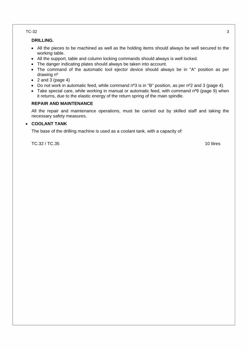
The base of the drilling machine is used as a coolant tank, with a capacity of:
TC.32 / TC.35 10 litres
4
O.K
O.K
DIBUJO 1DRAWING 1
MORDAZA GRIPVICE
3
A B
DIBUJO 2DRAWING 2
970 420 443 635
3493298204
3
2
1
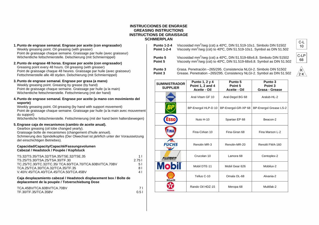
INSTRUCCIONES DE ENGRASE GREASING INSTRUCTIONS
INSTRUCTIONS DE GRAISSAGE SCHMIERPLAN
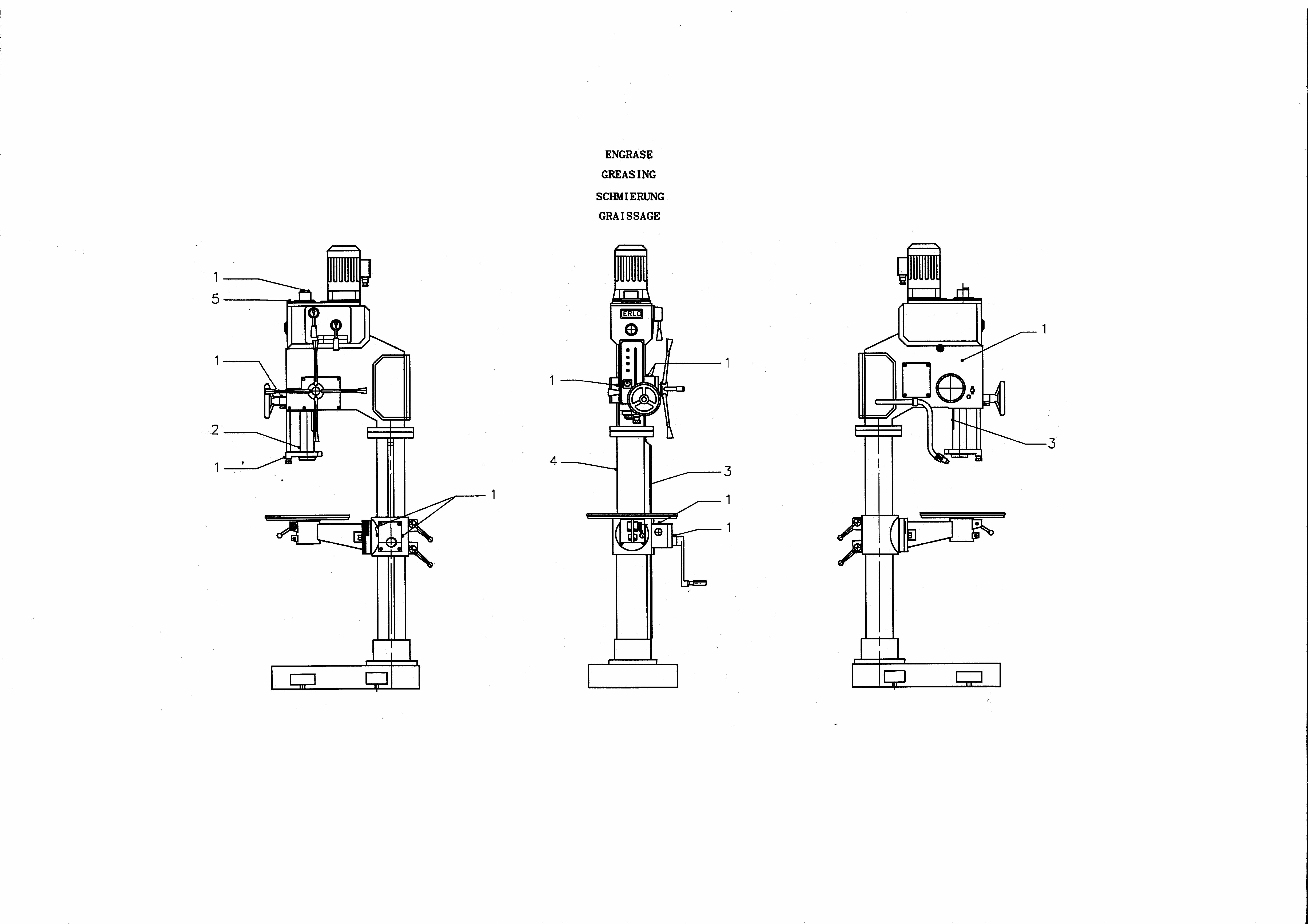
1. Punto de engrase semanal. Engrase por aceite (con engrasador) Weekly greasing point. Oil greasing (with greaser) Point de graissage chaque semaine. Graissage par huile (avec graisseur) Wöchentliche fettschmierstelle. Delschierung (mit Schmiernippel)
2. Punto de engrase 48 horas. Engrase por aceite (con engrasador) Greasing point every 48 hours. Oil greasing (with greaser) Point de graissage chaque 48 heures. Graissage par huile (avec graisseur) Fettschmierstelle alle 48 styden. Delschierung (mit Schmiernippel)
3. Punto de engrase semanal. Engrase por grasa (a mano) Weekly greasing point. Greasing by grease (by hand) Point de graissage chaque semaine. Graissage par huile (a la main) Wöchentliche fettschmierstelle. Fettschmierung (mit der hand)
4. Punto de engrase semanal. Engrase por aceite (a mano con movimiento del soporte) Weekly greasing point. Oil greasing (by hand with support movement) Point de graissage chaque semaine. Graissage par huile (a la main avec mouvement du support) Wöchentliche fettschmierstelle. Fettschmierung (mit der hand beim haltersbewegen)
5. Engrase caja de mecanismos (cambio de aceite anual). Gearbox greasing (oil tobe changed yearly). Graissage boîte de mecanismes (changement d’huile annuel). Schmierung des Spindelkopfes (Der Olwechsel ist järlirfich unter der Voraussetzung del einschichtigen Betriebes).
Capacidad/Capacity/Capacité/Fassungsvolumen Cabezal / Headstock / Poupée / Kopfstuck
TS.32/TS.35/TSA.32/TSA.35/TSE.32/TSE.35 1 l TS.25/TS.30/TSA.25/TSA.30/TF.30 2.75 l TC.25/TC.30/TC.32/TC.35/ TCA.60/TCA.70/TCA.60BV/TCA.70BV 5 l TCA.25/TCA.30/TCA.32/TCA.35/TF.35 8 l V.40/V.45/TCA.40/TCA.45/TCA.50/TCA.45BV 4 l
Caja desplazamiento cabezal / Headstock displacement box / Boîte de deplacement de la poupée / Totverschiebung Dose
TCA.45BV/TCA.60BV/TCA.70BV 7 l TF.30/TF.35/TCA.35BV 0.5 l
Punto 1-2-4 Viscosidad mm2/seg (cst) a 40ºC, DIN 51.519-10±1. Simbolo DIN 51502 Point 1-2-4 Viscosity mm2/seg (cst) to 40ºC, DIN 51.519-10±1. Symbol as DIN 51.502 Punto 5 Viscosidad mm2/seg (cst) a 40ºC, DIN 51.519-68±6.8. Simbolo DIN 51502 Point 5 Viscosity mm2/seg (cst) to 40ºC, DIN 51.519-68±6.8. Symbol as DIN 51.502 Punto 3 Grasa. Penetración –265/295. Consistencia NLGI-2. Simbolo DIN 51502 Point 3 Grease. Penetration –265/295. Consistency NLGI-2. Symbol as DIN 51.502
SUMINISTRADOR SUPPLIER
Punto 1, 2 y 4 Point 1, 2 and 4
Aceite - Oil
Punto 5 Point 5
Aceite - Oil
Punto 3 Point 3
Grasa - Grease
Aral-Vitam GF 10 Aral-Degol BG 68 Aralub-HL-2
BP-Energol HLP-D 10 BP-Energol-GR-XP 68 BP-Energol Grease LS-2
Nuto H-10 Spartan EP 68 Beacon-2
Fina-Cirkan 10 Fina-Giran 68 Fina Marson L-2
Renolin MR-3 Renolin-MR-20 Renolit FWA-160
Crucolan 10 Lamora 68 Centoplex-2
Mobil DTE-11 Mobil Gear 626 Mobilux-2
Tellus C-10 Omala OL-68 Alvania-2
Rando Oil HDZ-15 Meropa 68 Multifak-2
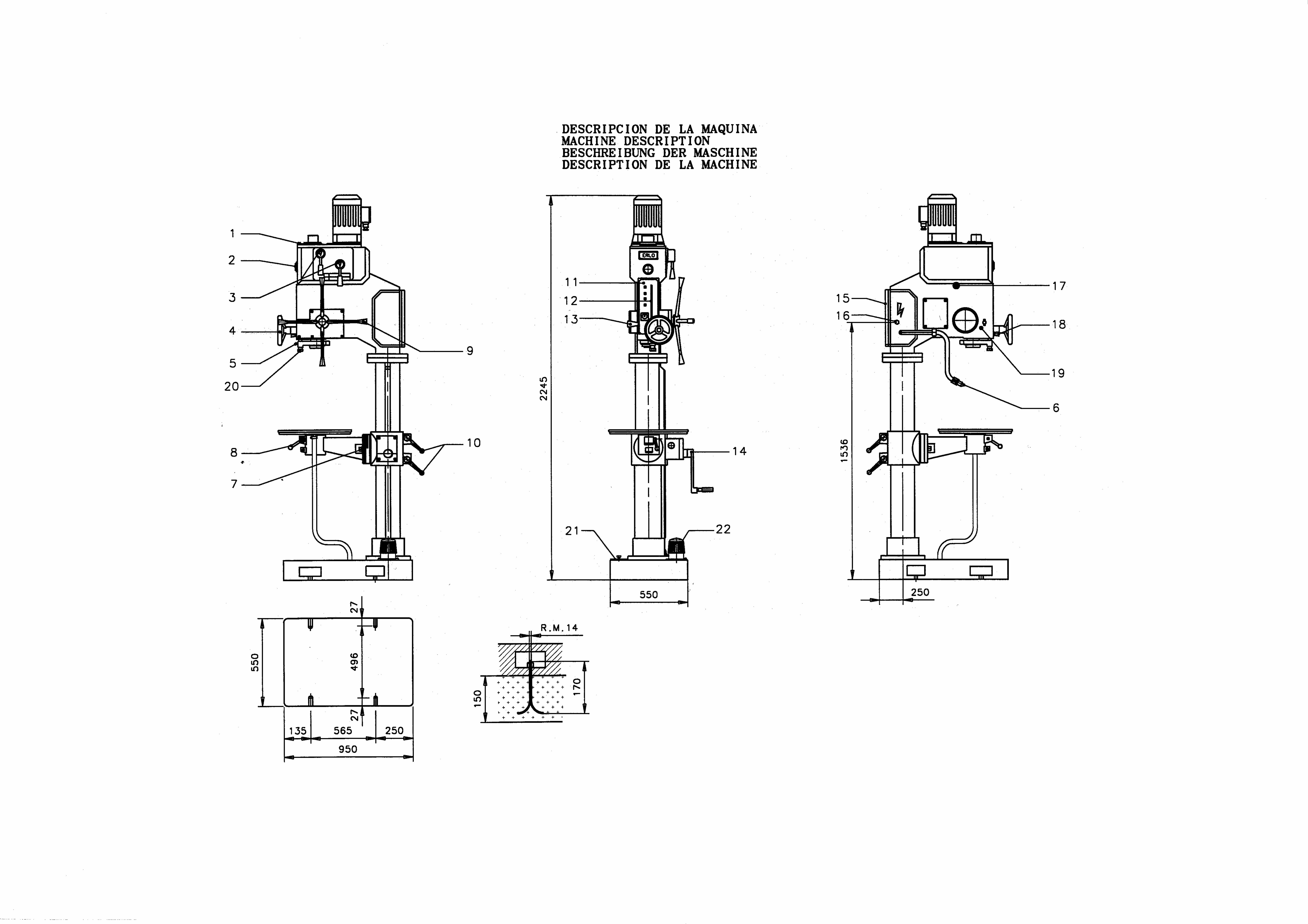
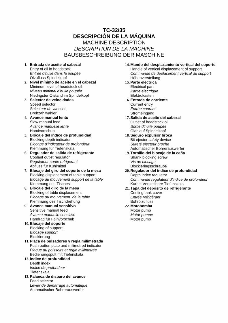
TC-32/35 DESCRIPCIÓN DE LA MÁQUINA
MACHINE DESCRIPTION DESCRIPTION DE LA MACHINE
BAUSBESCHREIBUNG DER MASCHINE
1. Entrada de aceite al cabezal Entry of oil in headstock Entrée d’huile dans la poupée Olzufluss Spindelkopf
2. Nivel mínimo de aceite en el cabezal Minimum level of headstock oil Niveau minimal d’huile poupée Niedrigster Olstand im Spindelkopf
3. Selector de velocidades Speed selector Selecteur de vitesses Drehzahlwähler
4. Avance manual lento Slow manual feed Avance manuelle lente Handvorschub
5. Blocaje del índice de profundidad Blocking depth indicator Blocage d’indicateur de profondeur Klemmung für Tiefenskala
6. Regulador de salida de refrigerante Coolant outlet regulator Regulateur sortie refrigerant Abfluss für Kühlmittel
7. Blocaje del giro del soporte de la mesa Blocking displacement of table support Blocage du mouvement support de la table Klemmung des Tisches
8. Blocaje del giro de la mesa Blocking of table displacement Blocage du mouvement de la table Klemmung des Tischdrehung
9. Avance manual sensitivo Sensitive manual feed Avance manuelle sensitive Handrad für Feinvorschub
10. Blocaje del soporte Blocking of support Blocage support Blockierung
11. Placa de pulsadores y regla milimetrada Push button plate and milimetred indicator Plaque du poissoirs et regle millimetrée Bedienungspult mit Tiefenskala
12. Índice de profundidad Depth index Indice de profondeur Tiefenskala
13. Palanca de disparo del avance Feed selector Levier de demarrage automatique Automatischer Bohrerauswerfer
14. Mando del desplazamiento vertical del soporte Handle of vertical displacement of support Commande de déplacement vertical du support Höhenverstellung
15. Parte eléctrica Electrical part Partie electrique Elektrokasten
16. Entrada de corriente Current entry Entrée courant Stromeingang
17. Salida de aceite del cabezal Outlet of headstock oil Sortie d’huile poupée Olablauf Spindelkopf
18. Seguro expulsor broca Bit ejector safety device Sureté ejecteur broche Automatischer Bohrerauswerfer
19. Tornillo del blocaje de la caña Shank blocking screw Vis de blocage Blockieringsschraube
20. Regulador del índice de profundidad Depth index regulator Commande regulateur d’indice de profondeur Kurbel Verstellbare Tiefenskala
21. Tapa del depósito de refrigerante Cooling tank cover Entrée refrigèrant Bohrölzufluss
22. Motobomba Motor pump Motor pumpe Motor pump
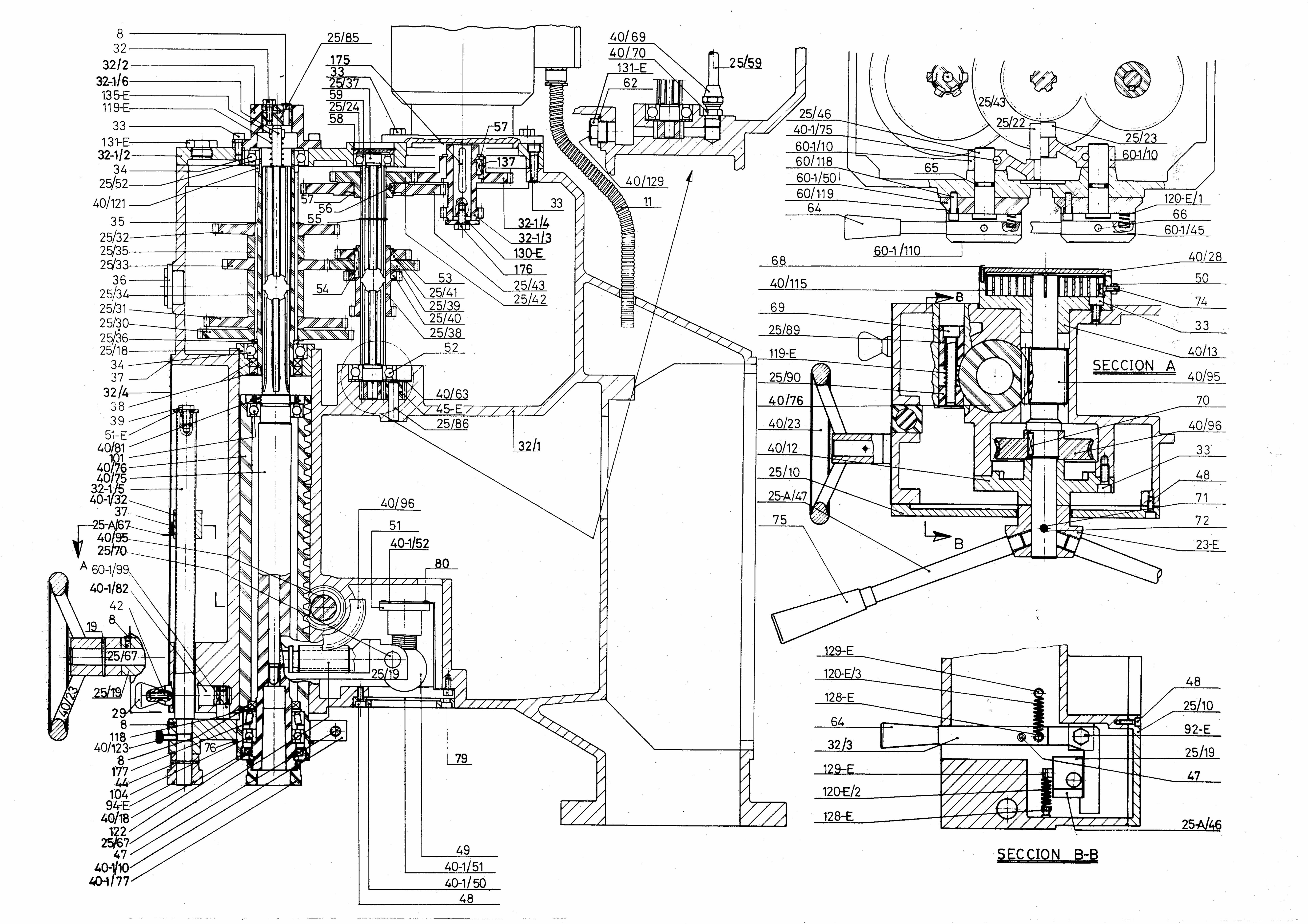

COD. DESCRIPCION DESCRIPTION COD. DESCRIPCION DESCRIPTION COD. DESCRIPCION DESCRIPTION32/1 Cabezal Headstock 40/1/32 Tuerca del husillo Spindle nut 66 Pasador elástico Ø6x55 Elastic pin Ø6x5532/2 Tapa rodamientos Bearing cover 40-1/50 Arandela sujeción bombilla Lamp protecting cover 68 Tornillo c/redonda M4x12 Round head screw M4x1232/3 Llanta disparo Release rim 40-1/51 Cristal protección bombilla Lamp protecting glass 69 Tornillo Allen RM10x60 Allen screw RM10x6032/4 Placa de pulsadores Push-button plate 40-1/52 Placa porta-lámpara Lamp holder plate 70 Chaveta media luna 6x25 Woodruff key 6x2525/10 Tapa lateral del cuadrado Lateral square cover 40-1/75 Bulón de apriete Connecting rod tightening pin 71 Pasador elástico Ø8x45 Elastic pin Ø8x4525/18 Cojinete porta-rodamientos Axle bearing holder 40-1/77 Tuerca protector rosca Thread protecting nut 72 Pasador elástico Ø6x45 Elastic pin Ø6x4525/19 Soporte sin-fin Continuous support 40/1/82 Bulón seguro expulsor Ejector safety pin 74 Tornillo c/hexagonal M6x15 Hexagonal head screw M6x1525/22 Zapatilla Protector 23-E Cubo porta aspas Arm holder hub 75 Pomo baquelita M10x90 Bakelite knob M10x9025/23 Zapatilla Protector 45-E Engrane bomba Pump gearing 76 Anilla elástica E-72 Elastic ring E-7225/24 Tapa de obturación Obturation cover 51-E Arandela husillo Spindle washer 79 Tornillo Allen RM6x10 Allen screw RM6x1025/30 Engraje fijo Fixed gearing 92-E Tornillo bulón del disparo Releasing screw pin 80 Tornillo c/redonda RM3x10 Round head screw RM3x1025/31 Engraje fijo Fixed gearing 94-E Manilla husillo Spindle handle 101 Rodamiento radial nº 6006 Radial bearing nº 600625/32 Engraje fijo Fixed gearing 119-E Muelle del expulsor Ejector spring 104 Rodamiento radial nº 6008 Radial bearing nº 600825/33 Engraje fijo Fixed gearing 120-E/1 Muelle manilla cambio Reversing handle spring 118 Retén Ø52xØ42x6,5 Seal Ø52xØ42x6,525/34 Distanciador engranes Gearing spacer 120-E/2 Muelle del sin-fin cuadrado Square continuous spring 122 Retén Ø62xØ50x10 Seal Ø62xØ50x1025/35 Distanciador engranes Gearing spacer 120-E/3 Muelle disparo Reversing spring 137 Chaveta 6x6x14 Key 6x6x1425/36 Distanciador Spacer 128-E Enganche del muelle Spring attachment 175 Chaveta 8x8x38 Key 8x8x3825/37 Eje estriado Splineshaft 129-E Enganche del muelle Spring attachment 176 Tornillo c/hexagonal RM.8x45 Hexagonal head screw RM.8x4525/38 Engrane móvil Floating gearing 130-E Arandela del motor Motor washer 177 Rodamiento cónico nº 32008X Conical bearing nº 32008X25/39 Engrane móvil Floating gearing 131-E Tapón salida aceite Oil outlet plug25/40 Engrane móvil Floating gearing 135-E Tope muelle expulsor Ejector spring stop25/41 Engrane móvil Floating gearing 60-1/10 Biela de cambio Change connecting rod25/42 Engrane móvil Floating gearing 60-1/45 Manilla cambios Change handle25/43 Engrane móvil Floating gearing 60-1/50 Mando cambios Change control25/46 Eje porta mando Control holder spindle 60-1/99 Pitón seguro expulsor Ejector safety peg25/52 Eje estriado Splineshaft 60-1/110 Placa indicadora Direction plate25/59 Tubo de bomba de aceite Ø8xØ10 Oil pump tube Ø8xØ10 60/118 Pitón arandela de mando Change control guide25/67 Eje sin fin Continuous spindle 60/119 Muelle pitón cambio Change guide spring25/70 Bulón del cuadrado Square pin 8 Engrasador de bola Ø6 Ball greasing Ø625/85 Tornillo graduado del expulsor Ejector adjusting screw 11 Tubo flexible PG 9-10x14x350 Flexible tube PG 9-10x14x35025/86 Bulón engrane bomba Pump gearing pin 19 Pasador cónico Ø6x60 Taper pin Ø6x6025/89 Casquillo apriete caña Shank tightening bush 29 Pomo cónico M6x25 Conical knob M6x2525/90 Casquillo apriete caña Shank tightening bush 32 Tornillo c/hexagonal M7x15 Hexagonal head screw M7x15
25-A/46 Pletina enganche cuadrado Square attachment strip 33 Tornillo Allen RM8x15 Allen screw RM8x1525-A/47 Manilla aspas Arm lever 34 Rodamiento radial nº 6007 Radial bearing nº 600725-A/67 Indice de profundidad Indicating needle 35 Anilla elástica E-42 Elastic ring E-4232-1/2 Tapa cabezal Head cover 36 Nivel de aceite Ø34,5x1,5 Oil level Ø34,5x1,532-1/3 Engrane motor Motor gearing 37 Tornillo c/estriada M4x7 (PHILLIPS) Grooved head screw M4x7 (PHILLIPS)32-1/4 Engrane motor Motor gearing 38 Retén Ø52xØ35x8 Seal Ø52xØ35x832-1/5 Husillo Spindle 39 Tornillo c/hexagonal M8x10 Hexagonal head screw M8x1032-1/6 Varilla expulsora Bit ejector rod 42 Espárrago M6x25 Stud M6x2540/12 Cojinete eje corona Spindle crown gearing 44 Pasador cónico Ø5x50 Taper pin Ø5x5040/13 Cojinete eje Axle bearing 47 Tornillo Allen M8x25 Allen screw M8x2540/18 Tuerca porta-reten Fastening holder nut 48 Tornillo Allen M6x15 Allen screw M6x1540/23 Volante Wheel 49 Lámpara de 125-130V 25W (E-27 Adorno) Lamp of 125-130V 25W (E-27 ornament)40/28 Tapa cojinete eje Axle gearing cover 50 Tuerca M6 Nut M640/63 Placa asiento bomba Pump seat plate 51 Porta lámpara nº 229 Lamp holder nº 22940/69 Tuerca racord bomba aceite Oil pump connection nut 52 Rodamiento radial nº 6204 Radial bearing nº 620440/70 Racord bomba aceite Oil pump connection 53 Anilla elástica E-35 Elastic ring E-3540/75 Eje principal Shank axle 54 Chaveta de 6x6x8 Key of 6x6x840/76 Casquillo bit holder spindle 55 Anilla elástica E-25 Elastic ring E-2540/81 Tuerca Nut 56 Chaveta de 6x6x8 Key of 6x6x840/95 Eje engrane caña Shank gearing axle 57 Anilla elástica E-38 Elastic ring E-3840/96 Corona Crown 58 Anilla elástica I-40 Elastic ring I-4040/115 Muelle espiral Coil spring 59 Rodamiento radial nº 6203 Radial bearing nº 620340/123 Tornillo moleteado fin de carrera End of travel knurling screw 62 Arandela salida aceite Oil outlet washer40/129 Placa indicadora salida aceite Oil outlet indicating plate 64 Pomo baquelita M8x60 Bakelite knob M8x6040-1/10 Abrazadera husillo Spindle clamp 65 Junta tórica AN-12 O-ring seal AN-12
RELACION DE PIEZAS DEL CABEZAL / HEADSTOCK PIECES LISTTC.32/35
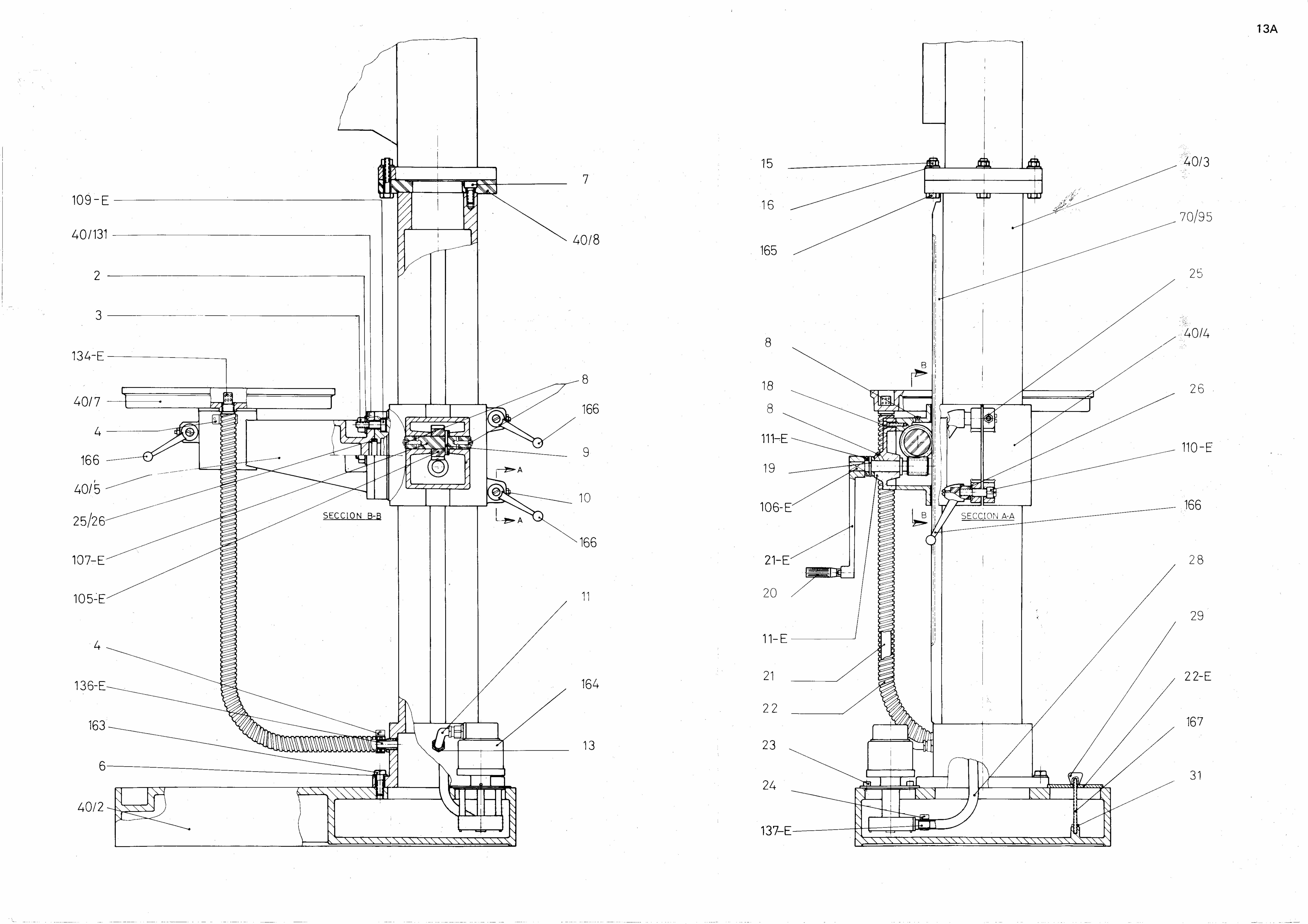

COD DESCRIPCION DESCRIPTION DESCRIPTION BESCHREIBUNG25/26 Casquillo guía soporte brazo Drill bushing arm support Bague de guidade support bras Armständerfürhrungsbüchse40/2 Base Base Base Basis40/3 Columna Column Colonne Säule40/4 Soporte columna Column support Support de colonne Säulenstutze40/5 Soporte brazo giratorio Support of giratory arm Support bras giratoire Schwenkbares Armständer40/7 Mesa Table Table Tisch40/8 Brida columna Column clamp Bride de colonne Säulenflansch
40/131 Placa graduación soporte Support graduation plate Plaque de graduation support Ständerabstufungsplatte11-E Tapa del soporte Support lid Couvercle du support Standerdeckel21-E Manivela Handle Manivelle Handkurbel22-E Tapa del depósito Tank lid Couvercle du reservoir Tankdeckel105-E Engrane del soporte Support gear Engrenage du support Ständereingriff106-E Sin fin del soporte Continuous of the support Sans fin du support Ständerchneche107-E Bulón del soporte Support pin Boulon du support Ständerbolzen109-E Tornillo giratorio soporte brazo Giratory screw arm support Vis giratoire support bras Armständer - Schwenkbare - Schraube110-E Tornillo soporte Support screw Vis du support Ständerchraube111-E Casquillo del soporte Support bushing Bague du support Ständerbuchse134-E Pitón salida taladrina plato Drilling oil peg plate outlet Tuyau sortie huile de plateau Scheibenbohröll ablaufstift136-E Pitón entrada taladrina Drilling oil peg entry Tuayu entrée huile de perçage Bohröllzuflusstift137-E Pitón salida taladrina bomba Drilling oil peg pump outlet Tuyau sortie huile de perçage pompe Pumpenbohröll ablaufstift70/95 Cremallera Toothed rack Cremaillière Zahnstange
2 Arandela DIN 125 M16 Washer DIN 125 M16 Rondelle DIN 125 M16 Scheibe DIN 125 M163 Tuerca DIN 934 M16 Nut DIN 934 M16 Ecrou DIN 934 M16 Schraubenmutter DIN 934 M164 Abrazadera MIKALOR 26x29 MIKALOR clamp 26x29 Anneau MIKALOR 26x29 MIKALOR Klammer 26x296 Arandela DIN 125 M14 Washer DIN 125 M14 Rondelle DIN 125 M14 Scheibe DIN 125 M147 Tornillo DIN 912 M14x40 Screw DIN 912 M14x40 Vis DIN 912 M14x40 Schraube DIN 912 M14x408 Engrasador de bola Ø8 Ball greaser Ø8 Graisseur a bille Ø8 Kugelöler Ø89 Pasador cónico Ø7x70 Taper pin Ø7x70 Goujon conique Ø7x70 Kegelstift Ø7x7010 Espárrago Allen M8x25 Allen stud M8x25 Goujon Allen M8x25 Allen Bolzen M8x2511 Tubo flex. P.G. 9/10x14x350 Flexible tube P.G. 9/10x14x350 Tube flex. P.G.9/10x14x350 Flex - Rohr P.G. 9/10x14x35013 Prensaestopa P.G. 13 Stuffing box P.G. 13 Presse-étoupe P.G 13 Einführungspresse P.G. 1315 Tuerca DIN 934 M14 Nut DIN 934 M14 Ecrou DIN 934 M14 Schraubenmutter DIN 934 M1416 Arandela DIN 125 M14 Washer DIN 125 M14 Rondelle DIN 125 M14 Scheibe DIN 125 M1418 Tornillo DIN 912 M8x30 Screw DIN 912 M8x30 Vis DIN 912 M8x30 Schraube DIN 912 M8x3019 Pasador cónico Ø 6x60 Taper pin Ø 6x60 Goujon conique Ø 6x60 Kegelstift Ø 6x6020 Manilla giratoria M.10x80 Rotating handle M.10x80 Poignée tournante M.10x80 Schwenkbarerhandriff M.10x8021 Manguera de plástico del plato a la columna Ø19xØ23x1070 Plastic hose from plate to column Ø19xØ23x1070 Tuyau d'arrossage du plateau a la colonne Ø19xØ23x1070 Plastikschlauch von der platte sur saule Ø19xØ23x107022 Funda VINKE del plato a la columna NR-21 Ø24xØ28x1200 VINKE sheath from plate to column NR-21 Ø24xØ28x1200 House VINKE du plateau a la colonne NR-21 Ø24xØ28x1200 Schutzhütle VINKE von der platte sur NR-21 Ø24xØ28x120023 Tornillo Allen M.8x15 Allen screw M.8x15 Vis Allen M.8x15 Schraube Allen M.18x1524 Abrazadera Mikalor 12x20 Mikalor clamp 12x20 Anneau Mikalor 12x20 Mikalor Klammer 12x2025 Tuerca M.8 Nut M.8 Ecrou M.8 Schraubenmutter M.826 Arandela M.16 Washer M.16 Rondelle M.16 Scheibe M.1628 Manguera de plástico del grifo a la motobomba Ø14xØ18x1800 Plastic hose from faucet to motor pump Ø14xØ18x1800 Tuyau d'arrosage en plastique du tuyau a la motopompe Ø14xØ18x1800 Plastikschlauch vom Hähn zur Motorpumpe Ø14xØ18x180029 Bola cónica M.6x25 Taper ball M.6x25 Bille conique M.6x25 Kegelförmigekugel M.6x2531 Tuerca DIN 934 M6 Nut DIN 934 M6 Ecrou DIN 934 M6 Schraubenmutter DIN 934 M6163 Tornillo c/hexagonal M14x45 Hexagonal head screw M14x45 Vis tête hexagonal M14x45 Seckseckigerkopf Schraube M14x45164 Motobomba AX-80 Motor pump AX-80 Moto-pompe AX-80 Motorpumpe AX-80165 Tornillo c/hexagonal M14x70 Hexagonal head screw M14x70 Vis tête hexagonal M14x70 Seckseckigerkopf Schraube M14x70166 Manilla BTH M.16 Handle BTH M16 Poignée BTH M16 Handgriff BTH M16167 Espárrago M6x135 Stud M6x135 Goujon M6x135 Bolzen M6x135
RELACION DE PIEZAS DEL SOPORTE COLUMNA/COLUMN SUPPORT PIECES LIST / LISTE DE PIECES DU SUPPORT COLONNE/TEILENVERZEICHNIS DES SAULENHALTERSTC-32-35
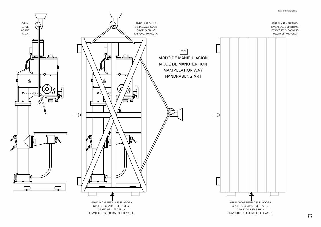
Cod: TC-TRANSPORTE13
TCMODO DE MANIPULACIONMODE DE MANUTENTION
MANIPULATION WAYHANDHABUNG ART
EMBALAJE JAULAEMBALLAGE COLIS
CAGE PACK NGKAFIGVERPAKKUNG
GRUA O CARRETILLA ELEVADORAGRUE OU CHARIOT DE LEVEGE
CRANE OR LIFT TRUCKKRAN ODER SCHUBKARPE ELEVATOR
GRUAGRUE
CRANEKRAN
GRUA O CARRETILLA ELEVADORAGRUE OU CHARIOT DE LEVEGE
CRANE OR LIFT TRUCKKRAN ODER SCHUBKARPE ELEVATOR
EMBALAJE MARITIMOEMBALLAGE MARITIMESEAWORTHY PACKING
MEERVERPAKKUNG

TS-25/30 260 Kg
SE-25/30
NOTA: Los pesos que se indican son aproximados
19
MODELS
MACHINE EMBALLAGECOLIS
Les poids indique sont approximatifs
TC/TCA
TCA-EMEL
TCM/TCMA
TCMA-EMEL
MAQUINA
200 Kg 230 Kg 270 Kg
255 Kg 320 Kg290 Kg
270 Kg 350 Kg310 Kg
EMBALAJEJAULA
270 Kg 310 Kg 350 Kg
317 Kg 417 Kg370 Kg
480 Kg 610 Kg560 Kg
560 kg 720 Kg640 Kg
660 Kg 835 Kg750 Kg
850 Kg 1090 Kg970 Kg
1040 Kg 1370 Kg1155 Kg
1150 Kg 1390 Kg1270 Kg
1350 Kg 1850 Kg1600 Kg
1500 Kg 2300 Kg1900 Kg
2120 Kg
MODELOS
3000 Kg2560 Kg
750 Kg 1150 Kg950 Kg
910 Kg 1400 Kg1155 Kg
680 Kg 870 Kg775 Kg
1025 Kg 1300 Kg1160 Kg
1050 Kg 1350 Kg1200 Kg
MODEL
T/TZ/TM/TR/S/SR/SG/SM/C/CR
TRV/TMV-18
MODELL
MACHINE
S/SR-30
C/CR-30
TS/TSA/TSE-32
MASCHINE
CAGRPACKING
25/30
32/35
40/45
50
60
KAFIGVERPAKKUNG
70
The shown weights are approximateDie zweckmassig gewichte sind annahernd
TCA-BV
45-BV
60-BV
70-BV
TF30
35
EMBALAJEMARITIMO
EMBALLAGEMARITIMESEAWORTHYPACKINGMEERVERPAKKUNG
25/30
32/35
40/45
Kg Kg Kg Kg
1825
Ref. Ref. Ref. Ref.
EQUIPAMIENTO EXTR A
EXTR A EQUIPMENT
EQUIPEMEN T SU PLEMENTAIRE
SONDERAUSR USTU NG