pageprinter network adapter: utility & environments · setting up network adapter 1-4 contents...
TRANSCRIPT

Contents
PagePrinterNetwork Adapter:
Utility & Environments


Ethernet FUtility Guide
Contents

the
e
for are en
d and ence is to
rty
c ser
Notice to American Users
This device complies with Part 15 of the FCC Rules. Operation is subject tofollowing two conditions:
(1) this device may not cause harmful interference, and
(2) this device must accept any interference received, including interferencthat may cause undesired operation.
Federal Communications CommissionRadio Frequency Interference Statement For United States UsersNotice: This equipment has been tested and found to comply with the limitsa Class A digital device, pursuant to Part 15 of the FCC Rules. These limitsdesigned to provide reasonable protection against harmful interference whthe equipment is operated in a commercial environment. This equipment generates, uses, and can radiate radio frequency energy and, if not installeused in accordance with the instruction manual, may cause harmful interferto radio communications. Operation of this equipment in a residential arealikely to cause harmful interference in which case the user will be requiredcorrect the interference at his own expense.
FCC Warning: Changes or modifications not expressly approved by the paresponsible for compliance could void the user’s authority to operate the equipment.
Notice to Canadian Users
This class A digital apparatus meets all requirements of the Canadian Interference-Causing Equipment Regulations.
Cet appareil numérique de la Classe A respecte toutes les exigences du Règlement sur le matériel brouilleur du Canada.
Notice to European Users
Warning: This is a product which meets Class A of EN55022. In a domestienvironment this product may cause radio interference in which case the umay be required to take adequate measures.
Contents

ol ld
d, ronic,
nc.
This document contains technology relating to strategic products controlled by export contrlaws of the producting and/or exporting countries. This document or a portion there of shounot be exported (or re-exported) without authorization from the appropriate governmental authorities in accordance with such laws.
Copyright FUJITSU LIMITED 1999. All Rights Reserved.
Copyright Lexmark International, Inc. 1999.
Printed in Spain. All rights reserved. No part of this manual may be reproduced or translatestored in a database or retrieval system, or transmitted, in any form or by any means, electmechanical, photocopying, recording, or otherwise, without the prior written permission of Lexmark International, Inc.
C150-E124-01EN, January 1999
Trademark Acknowledgment
Lexmark, MarkVision and Mark Net are registered trademark (s) of Lexmark International, I
The following companies own the other trademarks used in this manual:
Novell, Inc.: NetWare
Contents

Contents

...... v...... v..... v.....vi
..1-3..1-3...1-3
....1-4
.1-4
...1-4....1-5..1-5...1-5....1-6...1-6....1-6...1-6
...2-2.....2-3...2-3
Contents
Preface ...................................................................................................v
Introduction ...................................................................................................... vTerminology..................................................................................................Conventions used in this book ......................................................................Getting the utility ...........................................................................................How to use this manual.................................................................................
Chapter 1 Overview ............................................................................................. 1-1
Introduction ................................................................................................... 1-1
Environments we support............................................................................ 1-2
Functions....................................................................................................... 1-3Automatic topology detection........................................................................Automatic IP addressing (DHCP and WINS) ...............................................Automatic reconnection................................................................................
Setting up Network Adapter......................................................................... 1-4Step 1: Setup the printer .............................................................................Step 2: Familiarize yourself with the Network Adapter ................................Indicator lamps on the RJ-45 port ................................................................Ethernet........................................................................................................Step 3: Install the Network Adapter in a printer...........................................Step 4: Connect the printer to the network ..................................................Step 5: Power up .........................................................................................Step 6: Verify the connection.......................................................................Step 7: Continue .........................................................................................Step 8: Software installation ........................................................................
Chapter 2 Buttons and lights, normal operation .............................................. 2-1
Buttons .......................................................................................................... 2-1
Lights ............................................................................................................. 2-2Ready (idle) ..................................................................................................Job being processed ....................................................................................Flash operation taking place .........................................................................
Chapter 3 Adapter setup page............................................................................ 3-1
What is the adapter setup page................................................................... 3-1
How to print ................................................................................................... 3-1
i
Contents

Contents
... 4-3
... 5-2
.. 8-3... 8-4... 8-5
... 8-6
Sample page (Ethernet) ................................................................................3-2
Chapter 4 User menus page................................................................................4-1
What is the user menus page.......................................................................4-1
How to print user menus page.....................................................................4-1
Sample page ..................................................................................................4-2
How to use the buttons and lights...............................................................4-3
Example........................................................................................................
Chapter 5 Turning protocols on and off ............................................................5-1
How to turn protocols on and off.................................................................5-2Example........................................................................................................
Chapter 6 Changing settings ..............................................................................6-1
MarkVision™..................................................................................................6-1
Buttons and lights .........................................................................................6-1
Chapter 7 How to set an IP address ...................................................................7-1
BOOTP and hostname ..................................................................................7-1
MarkVision™..................................................................................................7-1
DHCP ..............................................................................................................7-2
BOOTP............................................................................................................7-2
RARP server and telnet ................................................................................7-3
Static ARP entry and telnet ..........................................................................7-4
Chapter 8 TCP/IP ..................................................................................................8-1
Get the adapter up and running...................................................................8-1
Standard TCP/IP protocols ...........................................................................8-2
Telnet ..............................................................................................................8-2
FTP..................................................................................................................8-3FTP timeout periods......................................................................................Carriage Return and Line Feed fixes............................................................Potential Problems .......................................................................................
TFTP ...............................................................................................................8-6
Examples ......................................................................................................
ii
Contents

Contents
.. 8-6
.. 8-6
.. 8-7.. 8-7.. 8-7
. 8-8
.... 8-9
... 8-9
e 10-2
10-410-40-5
10-510-6
0-710-8
TFTP timeout period .....................................................................................
LPR/LPD .........................................................................................................8-6
Using the LPR command ..............................................................................LPR timeouts and retry periods.....................................................................LPSTAT and LPQ commands .......................................................................Configuring LPD server options on the adapter............................................
SNMP ..............................................................................................................8-8SNMP Management Information Bases (MIBs)............................................
Finger .............................................................................................................8-9
Finger responses..........................................................................................Example........................................................................................................
Chapter 9 LexIP ....................................................................................................9-1
Prerequisites..................................................................................................9-1
Step 1: Add a new printer .............................................................................9-1
Step 2-1 (Windows 95 and Windows 98): Set up a workstation to use the printer .....................................................................................................9-2
Step 2-2 (Windows NT 4.x): Set up a workstation to use the printer........9-3
Chapter 10 Novell NetWare .................................................................................10-1
Prerequisites................................................................................................10-1
Step 1: Add a new printer ...........................................................................10-2
Using a Windows 95, Windows 98 or Windows NT 4.x client to configure thadapter for NetWare ..............................................................................
Step 2: Set up a client .................................................................................10-3
How to set up a client .................................................................................10-4Windows 95 or Windows 98 Client...............................................................Windows 3.x Client .......................................................................................Windows NT 4.x (or later) Client ................................................................. 1Windows NT 3.x Client.................................................................................DOS Client ....................................................................................................
NPRINTER/RPRINTER versus PSERVER ...................................... 10-7
Deciding whether to use NPRINTER/RPRINTER mode or PSERVER mode ......................................................................................................10-7
How NPRINTER/RPRINTER mode works ................................................. 1How PSERVER mode works ........................................................................
iii
Contents

Contents
0-90-10
0-110-11
1-211-2
12-5
A-2
NPRINTER versus PSERVER in IntraNetWare NetWare Directory Services (NDS) ..................................................................................... 10-9
NPRINTER mode in IntraNetWare NDS ..................................................... 1PSERVER mode in IntraNetWare NDS...................................................... 1
RPRINTER versus PSERVER in NetWare 3.x ......................................... 10-11
RPRINTER mode in NetWare 3.x .............................................................. 1PSERVER mode in NetWare 3.x ................................................................ 1
Chapter 11 Apple Talk..........................................................................................11-1
Prerequisites ............................................................................................... 11-1
Configure the adapter and printer............................................................. 11-1
Set up a workstation................................................................................... 11-2
If printer hardware is updated ................................................................... 11-2
In a LaserWriter 8 environment (prior to LaserWriter 8.4.1): ...................... 1In a LaserWriter 8 environment (LaserWriter 8.4.1 and later): ....................
Chapter 12 Troubleshooting ...............................................................................12-1
Commonproblems............................................................................................... 12-1
TCP/IP .......................................................................................................... 12-1
NetWare ....................................................................................................... 12-3
Network Adapter troubleshooting............................................................. 12-4
Error conditions.............................................................................................
Appendix A Using the printer control panel ........................................................A-1
Introduction ...................................................................................................A-1IP protocol settings from the printer control panel ........................................
Glossary ............................................................................................G-1
iv
Contents

s
s
.
th
e
Preface
Introduction Thank you for buying this multi-protocol network adapter. You can use thisguide to learn how to install and configure utilities so that your printer workwith:
• TCP/IP networks
• Windows 95/98 operating systems
• Windows NT operating systems
• Novell NetWare networks (Windows95/98)
• EtherTalk networks
Terminology
In this book, the term utilities refers to the files on the CD-ROM or diskettethat you received with the Network Adapter.
The term adapter refers to this Network adapter.
The term adapter list refers to the list of adapters on your network that the utility displays.
Conventions used in this book
• Steps requiring action are shown in bold print.
• Words or phrases requiring emphasis or explanation appear in italic print
• This book and the on-line Help information use slashes (/) to show the payou should follow through the menus and commands.
For example, suppose you want to print the adapter list to a printer. You would choose the File menu, the Print command under File, and the To Printer option. That path is shown as
File/Print/To Printer.
Getting the utility
The Network Printer Utility will be shipped on CD-ROM or diskettes with thNetwork Adapter.
v
Contents

Introduction
ou the
the
,
How to use this manual
• In this manual, you can move directly from the contents page to an item yare interested in. First, place the cursor on the desired item. Next, whencursor has changed to a pointing finger, click.
• To move to the contents page, click the Contents button at the bottom of page you are viewing.
• You can move from the last page of a chapter to the first page of the nextchapter. After confirming that the cursor has changed to a pointing fingerclick the page.
vi
Contents

s to
ch
ble rk.
CHAPTER
1 Overview
Introduction Network Adapter (sometimes called print server) is used to connect printernetworks. This lets many persons use these printers from their own workstations, a very cost effective way to share powerful and expensive printers. It is not necessary to buy an extra personal computer to attach eaprinter to the network. You use the network adapter instead.
Figure 1.1 Internal Network Adapter
Network Adapter is an optional card that fits inside a printer. You plug a cabetween the card and the network to attach the printer directly to the netwo
1-1
Contents

Environments we support
Environments we support
Network Adapter supports an extraordinarily wide range of network environments.
If you have this network...
NetWareNovell NetWare 3.11 or laterNovell NetWare 4.x or later (IntraNetWare)**includes NDS (Novell Directory Services)
Windows Windows NT Server (3.51, 4.x or later) Windows NT Workstation (3.51, 4.x or later)Windows 95 workgroupsWindows 98 workgroups
TCP/IP Direct printing (no server involved) via LexIP, FTP, LPR/LPD, or other means
UNIX Solaris 2.xHP-UX
Apple AppleTalk
1-2
ContentsContents

Functions
ork work on't
get
e is
e the
r is re-nd is
Functions Automatic topology detection
The Ethernet 10BaseT/100BaseTX models automatically detect your netwspeed (10 Mbps or 100 Mbps) and set themselves to match. So, if your netis running at 10 Mbps today and you upgrade to 100 Mbps tomorrow, you dhave to reconfigure the adapter.
Automatic IP addressing (DHCP and WINS)
Using DHCP (Dynamic Host Configuration Protocol) and WINS (Microsoft Windows Internet Naming Service) is by far the easiest and fastest way toyour Network Adapter up and running on an IP network.
If your IP network uses DHCP, a valid IP address for the adapter is automatically assigned. If your IP network uses WINS, the adapter hostnamautomatically resolved into the numerical IP address. If the DHCP server changes the adapter's IP address, you don't need to know about it becausWINS hostname remains constant.
If you don't have DHCP but need to set an IP address for the adapter, seeChapter 7 "How to set an IP address".
Automatic reconnection
If the network connection is temporarily lost (for example, if someone accidentally unplugs some cables in the wiring closet), the Network Adaptecan automatically recover. The adapter waits until the network connection established (no matter how long it takes), then automatically resets itself aready for print jobs again.
1-3
Contents

Setting up Network Adapter
a
e
ve
is
Setting up Network Adapter
This section describes the steps necessary to install a Network Adapter inprinter and physically connect the printer to a network.
Step 1: Setup the printer
If you have not done so already, set up the printer you want to attach to thnetwork. See to the printer documentation for instructions on setting up theprinter.
This Network Adapter is compatible with any of the Fujitsu printers that haan Internal Solutions Port (ISP).
Step 2: Familiarize yourself with the Network Adapter
This Network Adapter (Fast Ethernet) automatically senses if your network10 Mbps or 100 Mbps and adjusts itself for that speed.
Indicator lamps on the RJ-45 port
10/1
00B
-T
D L
S 2 1 C
M
T
10BaseT100BaseTXRJ-45
Fast Ethernet 10BaseT/100BaseTX
Leftindicatorlamp
Rightindicatorlamp
RJ-45 port on the adapter
1-4
ContentsContents

Setting up Network Adapter
e
d
Ethernet
Step 3: Install the Network Adapter in a printer
The Network Adapter fits inside the printer. Details such as how to open thprinter and find the correct connector vary from printer to printer. For this reason, see to printer documentation to install Network Adapter.
Caution: For safety reasons, make sure the printer power is turned off anthe printer power cord is unplugged during installation.
Step 4: Connect the printer to the network
• Use standard cabling that you use for other network components.
Left indicator lamp (shows link status)
Right indicator lamp (shows busy/idle status) INA Ethernet port is...
on - Linked to the network (Communication established)
off - Not linked to the network(Communication not established)
- blinking Transmitting or receiving data
- off Idle
Network port
RJ-45 connector UTP cable(unshielded twisted pair)
1-5
Contents

Setting up Network Adapter
rn
es of
.
e n
ct
Step 5: Power up
Plug the printer power cord into a properly grounded electrical outlet and tuthe printer on.
Step 6: Verify the connection
To confirm connection between the Network Adapter and a printer, print anadapter setup page by pressing and releasing the TEST button.
The adapter setup page can be printed at any time to view the current valuvarious parameters and the overall current state of the Network Adapter.
Step 7: Continue
You have completed hardware installation. Next, start software installation
Step 8: Software installation
Before you can start using your new network printer, you must configure thNetwork Adapter. The steps you take for configuration vary depending upothe network. For example, for TCP/IP you need to assign an IP address, netmask and gateway to the adapter. For Novell NetWare you need to seleeither PSERVER or RPRINTER/NPRINTER mode and set up queues.
For software installation, refer to the CD-ROM provided with the Network Adapter.
1-6
ContentsContents

pter e .
CHAPTER
2 Buttons and lights, normal operation
Buttons The buttons on the front of the adapter are labeled MENU and TEST.
Use the MENU and TEST buttons to:
• Reset the adapter. (Press and release MENU and TEST simultaneously.)
• Print an adapter setup page. (Press and release TEST.)
• Print a user menus page. (Press and release MENU.)
• Set certain parameters for the adapter. You can select which port the adasetup page and other informational pages print at, whether a banner pagprints between jobs or not, MAC speed and duplex settings, and so forth
10/100B-T
D
L
S
2
1
C
M T
MENU TEST
2-1
Contents

Lights
in
s n
on.
apter f the
Lights There are four indicator lights on the front of the Network Adapter. The mause for the lights is to indicate adapter status. Adapter status can be:
• Ready (idle) See "Ready (idle)"
• Job being processed See "Job being processed" .
• Flash operation taking place See "Flash operation taking place".
• Restarting When you reset the adapter, the lights cycle through a random-looking pattern. This is an indication the adapter is progressing through its variouhardware self tests. The lights should stabilize into the normal idle patterafter about a minute.
• Error condition If there is any other pattern on the lights, the adapter has an error conditi
Ready (idle)
This pattern, lights scanning back and forth endlessly, indicates that the adis not busy and is ready to accept print jobs. This is the normal idle state oadapter (print server).
Normal idle sequence(scan back and fort)
C 1 2 S 10/100B-T
D
L
S
2
1
C
M T
2-2
Contents

Lights
ia ly
ter ce
ny
Job being processed
If the Parallel 1 light is blinking, a print job is passing through the adapter vparallel port 1. When the light stops blinking, the print data has been entiredownloaded to the printer.
Flash operation taking place
The Caution light is related to firmware updating. When the Caution light isblinking, a flash file is downloading to a buffer on the adapter. When the Caution light is steady on, the flash file is being written to flash memory. Afthe flash operation is complete, the lights go through the power up sequen(adapter is restarting), then enter the normal idle sequence.
Important: Don't interrupt power to the adapter or printer and don't push abuttons until the flash operation is complete.
10/100B-T
D
L
S
2
1
C
M T
Parallel 1
10/100B-T
D
L
S
2
1
C
M T
Caution
2-3
Contents

Lights
2-4
Contents
tion
.
ters
/IP
he
CHAPTER
3 Adapter setup page
Network Adapters, and many printers store one or more "informational
pages" in memory. These pages contain important information about your
specific adapter or printer, and you can print the pages to read this informa
whenever you want.
There are adapter setup page and user menu page on informational pages
What is the adapter setup page
The adapter setup page is an extensive list of adapter and network parame
and their current values. These include the 12-digit hardware address, TCP
address, adapter firmware revision level, active network protocols, NPAP status, PSERVER or RPRINTER mode, and so on.
The adapter setup page is:
• stored in the adapter
• used during adapter installation
• used to check adapter configuration at any time
• used to check the overall state of the adapter at any time
How to print To print the adapter setup page for a Network Adapter, press and release tTEST button of the adapter.
The page prints at one of the printers attached to the Network Adapter.
3-1
Contents

Sample page (Ethernet)
Sample page (Ethernet)
Network Adapter adapter setup page
Ethernet 10/100
Network CardStatus:Speed, Duplex: End-of-Job Timeout:UAA (MSB, Canonical):LAA:Part Number:EC:Firmware, Bootcode Revision:Compi:
Connected100 Mbps, Half Duplex90002000200039 00040004009C000000000000 00000000000016A003401A0005, MN_XL_E2.7.1, 7.0thr.sh2.pospir.27.08.18.97.15.34
->Parallel Port 1<-NPAP Active, NPAP Mode:Busy Timeout:Printer Type, Port Type:
Yes, Auto90Print Partner 20W, Enhanc
TCP/IPActive:DHCP, BOOTP, RARP Enabled:Address Source:Address:Netmask:Gateway:Hostname, WINS Status:WINS Server:
YesYes, Yes, YesBOOTP192.168.10.45255.255.255.0192.168.10.1LXK200039, Unregistered0.0.0.0
NetWareActive:Login Name:Mode:Network Number:
Yes!LEX002000200039PSERVER000C2192
AppleTalk*Parallel 1
Active:Name:Type:Zone:
YesL200039 A Lexmark Optra LaserPrLaserWriterEthertalk
Address: 65408.195
*AppleTalk is a trademark of Apple Computer, Inc.
3-2
Contents

the of
le or
m
ir
CHAPTER
4 User menus page
What is the user menus page
The user menus page lists the set of parameters you can modify by using buttons and lights on the Network Adapter. It also shows the current valuesthose parameters.
The user menus page is:
• stored in the adapter
• used to set Network Adapter parameters when no other method is possibconvenient
The list of parameters may vary between Network Adapter models and froone firmware revision level to another.
Note: To see a more extensive list of Network Adapter parameters and thecurrent values, print the adapter setup page.
How to print user menus page
To print the user menus page, press and release the MENU button on the Network Adapter.
The page prints at one of the printers attached to the Network Adapter.
4-1
Contents

Sample page
f
s.
Sample page
USER MENUS Press and release the MENU button to print this page.
Entering the USER MENUS:To enter USER MENU mode, hold down the MENU button until all four lights turn on (about 3 seconds). When the MENU button is released, USER MENU mode willbegin.
MENU Operation:The USER MENUS are a two tiered system. A menu consists of a repeating count obinary light patterns. You make a menu selection by pressing and releasing the MENU button when the binary light pattern of the menu item you want to select is displayed. All of the lights will turn on for 1 second when the MENU button is released to indicate a selection has been made.
The USER MENUS may be exited without any function being performed by pressing and releasing the TEST button. This can be done in either tier of the menu
1: GENERAL1: ->Set The Print Language For Internal and Banner Pages to PS<-2: Set The Print Language For Internal and Banner Pages to ASCII
2: Parallel port 11: Toggle Always Add A Form Feed After Job: Yes / ->No<- .2: Toggle Banner Page: On / ->Off<- .3: Toggle Force 1284 Mode Off: Yes / ->No<- .
3: NETWARE1: Toggle Packet Burst: On / ->Off<- . 2: Toggle NetWare NSQ/GSQ Connection Algorithm: On / ->Off<- .
4: Set MAC Speed and Duplex Settings To: 1: ->Auto<-2: 10 Mbps, Half Duplex3: 10 Mbps, Full Duplex4: 100 Mbps, Half Duplex5: 100 Mbps, Full Duplex
4-2
Contents

How to use the buttons and lights
ter
lex,
four
How to use the buttons and lights
Look at the menu hierarchy on the sample page. The available settings areorganized in a two-tier hierarchy. Each number in a tier represents a binarypattern on the four indicator lights (0-15). To select an item, press the adapMENU button immediately after your light pattern becomes visible.
Example
If you want to set the MAC speed to 100 Mbps and the adapter to half dupdo these steps:
1 Print a user menus page. To do this, press and release the MENU button on Network Adapter.
2 Locate the parameter you want to change (MAC speed=100Mbps and duplex setting=half duplex).
• Set MAC Speed and Duplex Settings To: is "6" in the first tier and
• 100 Mbps, Half Duplex is "4" in the second tier.
3 Enter user menu mode. To do this, press and hold the Network Adapter MENU button until all four indicator lights turn on. This takes about threeseconds.
4 Watch the lights cycle through the first tier. In our example, the first tier is 1, 2, 3, 4, 5, 6 and repeat. The numbers are expressed in binary on the indicator lights.
5 When the lights display binary 6, press the MENU button. Binary 6 is: off, on, on, off (left to right on the indicator lights).
6 Release the MENU button. All four lights turn on briefly to let you know you made a selection. You have entered the second tier.
7 Watch the lights cycle through the second tier. In our example, the secondtier under item 6 is 1, 2, 3, 4, 5 and repeat.
8 When the lights display binary 4, press the MENU button. Binary 4 is: off, on, off, off.
9 Release the MENU button. All four lights turn on briefly to let you know you made a selection. You have selected 100 Mbps and half duplex.
The adapter automatically resets itself (if necessary) and reverts to normal idle mode.
10 To verify that you changed the setting successfully, print the user menuspage again. Make sure 100 Mbps, Half Duplex has arrows pointing to it. This indicates that it is selected.
4-3
Contents

How to use the buttons and lights
and
Note: To quit user menu mode without making any changes, press the TESTbutton. If you change a setting accidentally, re-enter user menu modechange it back.
4-4
Contents
ed r
sent
via up in
CHAPTER
5 Turning protocols on and off
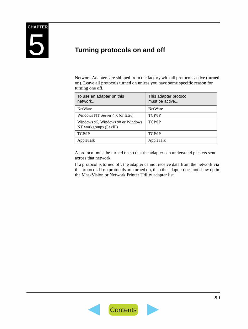
Network Adapters are shipped from the factory with all protocols active (turnon). Leave all protocols turned on unless you have some specific reason foturning one off.
A protocol must be turned on so that the adapter can understand packets across that network.
If a protocol is turned off, the adapter cannot receive data from the networkthe protocol. If no protocols are turned on, then the adapter does not show the MarkVision or Network Printer Utility adapter list.
To use an adapter on this network...
This adapter protocol must be active...
NetWare NetWare
Windows NT Server 4.x (or later) TCP/IP
Windows 95, Windows 98 or Windows NT workgroups (LexIP)
TCP/IP
TCP/IP TCP/IP
AppleTalk AppleTalk
5-1
Contents

How to turn protocols on and off
How to turn protocols on and off
Use MarkVision to turn protocols on and off inside a Network Adapter.
Note: MarkVision for Macintosh affects only the AppleTalk protocol.
Example
To use MarkVision for Windows to turn TCP/IP on the Network Adapter, follow these steps:
1 In the MarkVision printer window, double-click one of the Network Adapter ports.
2 Click the Adapter Settings tab.
3 Click Advanced Settings.
4 Find the area labeled Set Active Protocols.
5 Put a checkmark in the TCP/IP box.
6 Click OK.
Note: If a protocol is grayed out and checked, it is turned on and cannot beturned off. In this case, MarkVision has chosen that protocol to communicate with the adapter for configuration purposes.
5-2
Contents

al
ter ur
he you s
CHAPTER
6 Changing settings
If you need to modify any of the Network Adapter settings, you have severchoices:
• MarkVision
• Buttons and lights on the Network Adapter
MarkVision™ These are the versions of MarkVision you can use to change network adapsettings. Use the chart to select the MarkVision that applies to you and yonetwork.
Buttons and lights
You can set basic parameters for the Network Adapter manually by using tfour lights and two buttons on top of the adapter. This may be helpful whenspecifically need to modify one of these parameters and no other method ipossible or convenient.
To learn more, press and release the Menu button on top of the Network Adapter to print the user menus page.
Tools Client
Networks that are applicable to adapter settings
MarkVision for Windows 95/98 and Windows NT
Windows 95 or Windows 98
NetWare, Windows NT Server (3.51, 4.x or later), Windows NT Workstation
6-1
Contents

Buttons and lights
6-2
Contents

el have
n the u set
t is nter
rk To ust
e, on.
ct
or d f . o the not
CHAPTER
7 How to set an IP address
BOOTP andhostname
Setting the IP address, netmask, and gateway via the printer operator panaffects this adapter only and does not update any BOOTP records you mayin your server.
After you finish at the printer operator panel, set up the adapter hostname icomputer. To do so, simply define the adapter IP name and address in the/etc/hosts file or on the name server. This address must match the IP address yoearlier on the printer operator panel. You may want to use a hostname thameaningful in your environment (for example, a name that identifies the prilocation).
MarkVision™ A simple way to set the IP address, netmask, and gateway inside a NetwoAdapter is to use one of the utilities on the CD that comes with the printer. do this, you must have a multi-protocol environment. In other words, you mbe running some network operating system other than TCP/IP (such as NetWare, Windows NT Server, or Windows 95/98 Workgroups). In this casyou can quickly setup the IP parameters for the adapter by using MarkVisi
The reason you must have a multi-protocol environment is related to the fathat TCP/IP disallows network devices to broadcast their presence on the network. Before a utility can set the IP address, netmask, or gateway in anadapter, it has to find the adapter on the network. If the network is NetWarethe others mentioned before, then the adapter broadcasts its presence, anMarkVision finds it and allows you to specify the IP parameters. However, ithe network is TCP/IP only, the adapter is silent and invisible to the utilitiesThe adapter cannot broadcast its presence. The adapter cannot respond tutility (which may know the correct IP address) because the adapter does yet know its own IP address.
7-1
Contents
DHCP
r
e
me)
nce e ss, P
i-
ss.
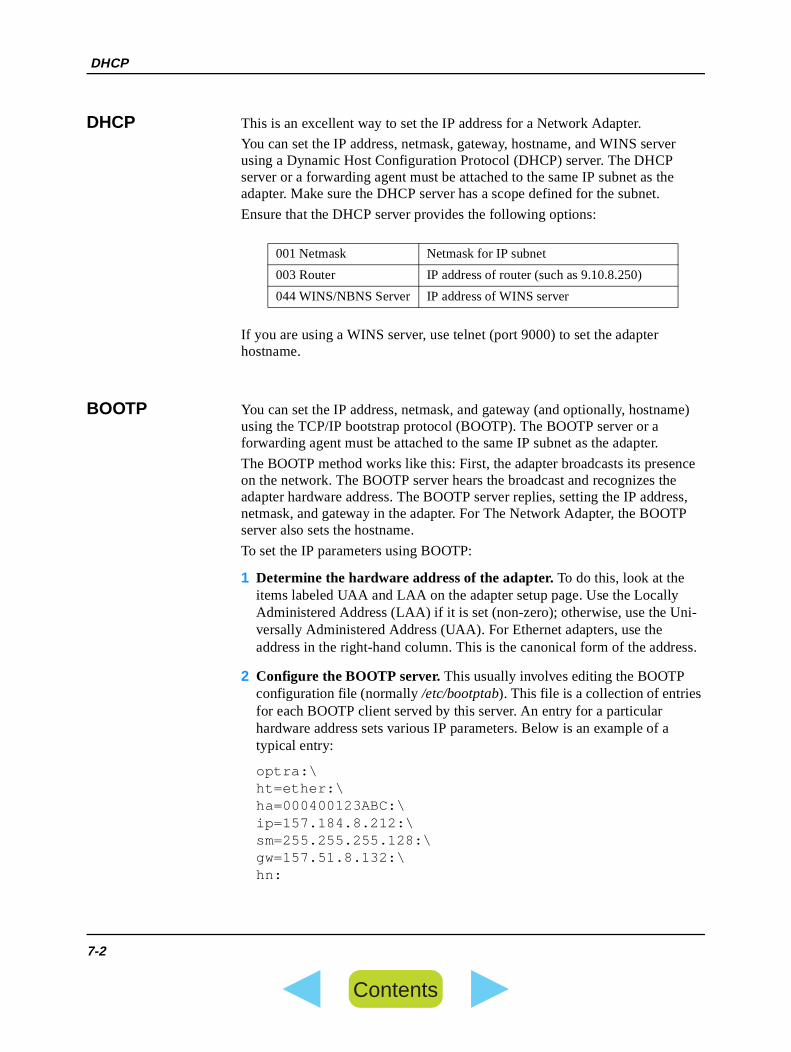
DHCP This is an excellent way to set the IP address for a Network Adapter.
You can set the IP address, netmask, gateway, hostname, and WINS serveusing a Dynamic Host Configuration Protocol (DHCP) server. The DHCP server or a forwarding agent must be attached to the same IP subnet as thadapter. Make sure the DHCP server has a scope defined for the subnet.
Ensure that the DHCP server provides the following options:
If you are using a WINS server, use telnet (port 9000) to set the adapter hostname.
BOOTP You can set the IP address, netmask, and gateway (and optionally, hostnausing the TCP/IP bootstrap protocol (BOOTP). The BOOTP server or a forwarding agent must be attached to the same IP subnet as the adapter.
The BOOTP method works like this: First, the adapter broadcasts its preseon the network. The BOOTP server hears the broadcast and recognizes thadapter hardware address. The BOOTP server replies, setting the IP addrenetmask, and gateway in the adapter. For The Network Adapter, the BOOTserver also sets the hostname.
To set the IP parameters using BOOTP:
1 Determine the hardware address of the adapter. To do this, look at the items labeled UAA and LAA on the adapter setup page. Use the LocallyAdministered Address (LAA) if it is set (non-zero); otherwise, use the Unversally Administered Address (UAA). For Ethernet adapters, use the address in the right-hand column. This is the canonical form of the addre
2 Configure the BOOTP server. This usually involves editing the BOOTP configuration file (normally /etc/bootptab). This file is a collection of entries for each BOOTP client served by this server. An entry for a particular hardware address sets various IP parameters. Below is an example of atypical entry:
optra:\ht=ether:\ha=000400123ABC:\ip=157.184.8.212:\sm=255.255.255.128:\gw=157.51.8.132:\hn:
001 Netmask Netmask for IP subnet
003 Router IP address of router (such as 9.10.8.250)
044 WINS/NBNS Server IP address of WINS server
7-2
Contents

RARP server and telnet
g on nd
net:
i-
ss.
e.
where:
optra is the hostname.ht=ether is the hardware type (Ethernet).ha=000400123ABC is the hardware address.ip=157.184.8.212 is the IP address.sm=255.255.255.0 is the netmask.gw=157.51.8.1 is the gateway.hn: means the server should send the hostname to the
adapter, and the adapter should store it. The hn.
If you need help configuring your BOOTP server, consult your system documentation.
3 Make sure that BOOTP is enabled.
You can do this from the printer operator panel or from within the Network Printer Utility for another environment (such as NetWare, or Windows NT).
4 Set up the printer hostname in the computer. To do so, simply define the printer IP name and address in the /etc/hosts file or on the name server.
This IP address and hostname must match those you set earlier in the BOOTP file. You may want to use a hostname that is meaningful in your environment (for example, a name that identifies the printer location).
RARP server and telnet
You can set the IP address using a RARP server. Make sure you are workinthe same physical network as the adapter. Then you can set the netmask agateway with telnet.
To set the IP address, netmask, and gateway using a RARP server and tel
1 Determine the hardware address of the adapter. To do this, look at the items labeled UAA and LAA on the adapter setup page. Use the LocallyAdministered Address (LAA) if it is set (non-zero); otherwise, use the Unversally Administered Address (UAA). For Ethernet adapters, use the address in the right-hand column. This is the canonical form of the addre
2 Make sure RARP is enabled. Check the adapter setup page or printer operator panel.
3 Set up the RARP server. Follow the instructions provided by your host operating system. Use the hardware address determined in step 1 abov
4 Reset the adapter. Press the TEST and MENU buttons at the same time. Turn the printer off, then on again.
The adapter sends a RARP request, and the server responds.
7-3
Contents

Static ARP entry and telnet
e in
u add bnet net.
lnet:
i-
ss.
of to the ld
ace
5 Use telnet to access the adapter. For UNIX systems, the command is:
telnet address 9000
where address is the adapter hostname (or adapter IP address in dotted decimal format, such as 157.184.8.212). The adapter port is 9000.
6 Follow the instructions on the screen to set the netmask and gateway. If you want to change the IP address, netmask, gateway, or community namthe future, you may find this telnet interface helpful.
Static ARP entry and telnet
To set the adapter IP address, netmask, and gateway using this method, yoa static entry to the ARP table on some computer that is on the same IP suas the adapter. (Source Route bridging is not supported.) Then, you use tel
To set the IP address, netmask, and gateway using static ARP entry and te
1 Determine the hardware address of the adapter. To do this, look at the items labeled UAA and LAA on the adapter setup page. Use the LocallyAdministered Address (LAA) if it is set (non-zero); otherwise, use the Unversally Administered Address (UAA). For Ethernet adapters, use the address in the right-hand column. This is the canonical form of the addre
2 Add a static ARP entry for the IP address. Use the hardware address determined in step 1 above. Make sure you use the dotted decimal formthe IP address, such as 157.184.8.231. Use the commands appropriatehost operating system. For example, on many UNIX computers you woutype something like:
arp -s ether 157.184.8.231 00:04:00:30:00:44
If you need help and are using a UNIX system, try the man page.
3 Use telnet to access the adapter. For UNIX systems, the command is:
telnet address 9000
where address is the adapter hostname (or adapter IP address in dotted decimal format, such as 157.184.8.212). The adapter port is 9000.
4 Follow the instructions on the screen to set the adapter IP address, netmask and gateway. If you want to change the IP address, netmask, gateway, or community name in the future, you may find this telnet interfhelpful.
7-4
Contents
sses
,
ss is
CHAPTER
8 TCP/IP
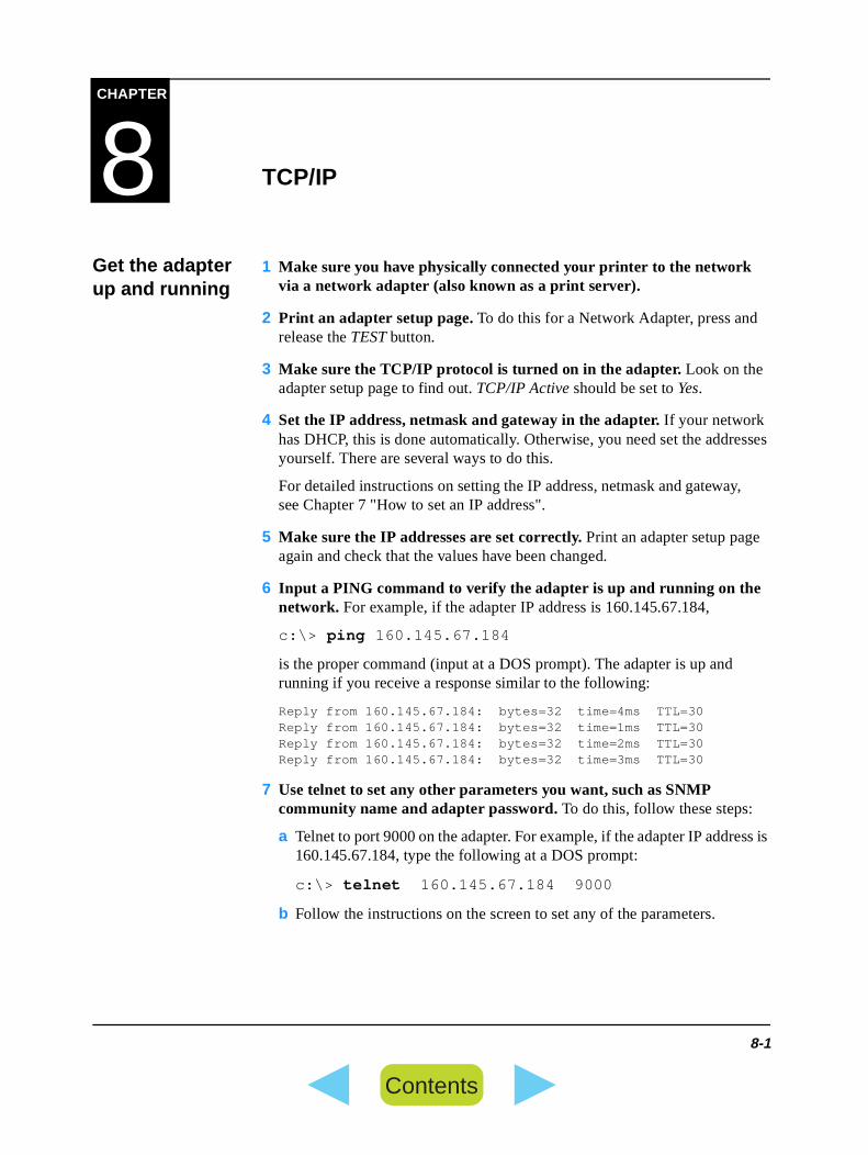
Get the adapter up and running
1 Make sure you have physically connected your printer to the network via a network adapter (also known as a print server).
2 Print an adapter setup page. To do this for a Network Adapter, press andrelease the TEST button.
3 Make sure the TCP/IP protocol is turned on in the adapter. Look on the adapter setup page to find out. TCP/IP Active should be set to Yes.
4 Set the IP address, netmask and gateway in the adapter. If your network has DHCP, this is done automatically. Otherwise, you need set the addreyourself. There are several ways to do this.
For detailed instructions on setting the IP address, netmask and gatewaysee Chapter 7 "How to set an IP address".
5 Make sure the IP addresses are set correctly. Print an adapter setup page again and check that the values have been changed.
6 Input a PING command to verify the adapter is up and running on the network. For example, if the adapter IP address is 160.145.67.184,
c:\> ping 160.145.67.184
is the proper command (input at a DOS prompt). The adapter is up and running if you receive a response similar to the following:
Reply from 160.145.67.184: bytes=32 time=4ms TTL=30Reply from 160.145.67.184: bytes=32 time=1ms TTL=30Reply from 160.145.67.184: bytes=32 time=2ms TTL=30Reply from 160.145.67.184: bytes=32 time=3ms TTL=30
7 Use telnet to set any other parameters you want, such as SNMP community name and adapter password. To do this, follow these steps:
a Telnet to port 9000 on the adapter. For example, if the adapter IP addre160.145.67.184, type the following at a DOS prompt:
c:\> telnet 160.145.67.184 9000
b Follow the instructions on the screen to set any of the parameters.
8-1
Contents

Standard TCP/IP protocols
er,
ng
on-
.
d
Standard TCP/IP protocols
This section explains how to use standard TCP/IP protocols with the adaptspecifically:
• Telnet.
• File Transfer Protocol (FTP).
• Trivial File Transfer Protocol (TFTP).
• Line Printer Remote and Line Printer Daemon (LPR/LPD).
• Simple Network Management Protocol (SNMP).
• Finger.
Telnet You can set adapter parameters easily with telnet. Make sure you are settitelnet on the same physical network as the adapter.
To use telnet:
1 Set up the host to telnet in line mode, with local echo, and with CR/LF cversion.
2 If a password is set for Network Adapter, be sure you have the password
3 Type the following at the command prompt:
telnet address 9000
where address is the hostname or IP address of the adapter you're using.
4 Follow the instructions on the screen. You can modify many adapter parameters. For example, you can do the following things:
• Set IP address, netmask, gateway, and hostname
• Set community name
• Set password
• Set LPD options (such as automatic carriage returns, banner page, antimeout)
• Enable or disable DHCP, BOOTP, RARP, FTP, and TFTP
• Set Maximum Transmission Unit
• Set restricted server list
• Set Printer port Cofiguration
Note: This board does not support HTTP. So, HTTP setting does not effective.
8-2
Contents

FTP
o the a
apter s) to
ued reply
t
t
t ther
FTP You can use FTP (File Transfer Protocol) to send a job across the network tprinter. This Network Adapter accepts any username and does not requirepassword.
For example, the following commands establish an FTP session with an adhaving IP address 149.213.82.145, and cause a PostScript file (c:\report.pbe printed.
c:\> FTP 149.213.82.145Connected to 149.213.82.145.220 LXK2001C7 Ethernet-F FTP Server 1.8.15 ready.User (149.213.82.145:(none)):230 User (none) logged in.ftp> put report.ps200 PORT command successful.150 Opening ASCII data connection (149.213.185.133,1034).226 Transfer complete.927 bytes sent in 0.06 seconds (15.45 Kbytes/sec)ftp> bye221 Good-bye.
FTP timeout periods
There are two timeout periods that may occur in FTP: one on the control connection and one on the data connection.
The timeout on the control connection is 60 seconds. If no command is issfor 60 seconds, then the control session is closed. The adapter sends a 421code ("Inactivity timeout").
The timeout on the data connection is governed by the End-of-Job Timeou(default is 90 seconds).
This timeout value can be changed with telnet.
Select "Parallel 1" from "Printer Port Configuration" and set the time in "Seport timeout".
If data is not received from the host for this data timeout period, then the adapter closes the FTP data session and releases the printer. This timeouprevents incomplete print jobs from hanging up in the printer and keeping ojobs from printing.
8-3
Contents

FTP
end le.
Carriage Return and Line Feed fixes
If you are having problems with carriage returns or line feeds, you can appthe destination port or queue name with the parameters in the following tab
For example, a port named par1_cr would cause a file to be sent to the printer attached to parallel port 1 of the Network Adapter and would add a carriage return (or line feed) at the end of each line of text.
Parameter (suffix) added to name: Purpose:
Command in file:
Translates in queue to:
no suffix added to port or queue name
Sends print jobs to the port or queue as is.
<CR> <CR>
<LF> <LF>
_cr Fixup for lone CRs (carriage return characters) and lone LFs (line feed characters).It causes the adapter to add a carriage return (or line feed, if appro-priate) at the end of each line of text.
<CR> <CR> <LF>
<LF> <CR> <LF>
<CR> <LF> <CR> <LF>
_lf Fixup for lone LFs (line feed charac-ters) only.It causes the adapter to add a carriage return at the end of each line of text.
<CR> <CR>
<LF> <CR> <LF>
<CR> <LF> <CR> <LF>
8-4
Contents

FTP
ms,
Potential Problems
The following examples may help you pinpoint any problems you may be having with carriage returns or line feeds.
Problem 1
This problem is caused by lone line feeds, or LFs:
The night swirls
in ambiguity,
its ominous hues
made surreal by the moon.
This can be fixed by appending the port or queue name with _cr . Your file should then print like this:
The night swirlsin ambiguity,its ominous huesmade surreal by the moon.
Note: If the file only has line feed problems, and no carriage return probleyou could also fix the print job by appending the port or queue name with_lf .
Problem 2
This problem is caused by lone carriage returns, or CRs:
This can also be fixed by appending the port or queue name with _cr . Your file should then print like this:
Uncertainty can be the shackles that bind us,yet can be the keys to freedom as well.
Uncertainty can be the shackles that bind us,yet can be the keys to freedom as well.
8-5
Contents

TFTP
s the rint
N
d e a to
or et
on st.
, s d
TFTP You can use TFTP (Trivial File Transfer Protocol) to send a job over the network to the printer. TFTP is similar to FTP, but slower.
Examples
• This TFTP command causes the file (report.ps) to be printed.
tftp> put report.ps
TFTP timeout period
Network Adapter's TFTP protocol includes a 30-second inactivity timeout.
If data is not received from the host for 30 seconds, then the adapter closeTFTP session and releases the printer. This timeout prevents incomplete pjobs from hanging up in the printer and keeping other jobs from printing.
LPR/LPD You may already use Line Printer Remote and Line Printer Daemon (LPR/LPD) programs to send print jobs. LPR/LPD is the most common way a SUor other UNIX workstation connects to a network printer.
The LPR program usually runs on the host computer, sending print jobs ancontrol files to the LPD program running on the print server. Adapters includline printer daemon. This daemon prints previously formatted data files, asreceived, and ignores the control file. You can use your LPR/LPD programsend jobs to the adapter's line printer daemon.
Using the LPR command
When you use LPR commands, be sure that:
• server is the IP address (hostname) of the adapter
• queue name or remote queue name is the name of the queue that you set up fthis adapter. It specifies the destination for the queue and allows you to scertain parameters that will apply to all print jobs sent to the queue.
Note:
• If you specify a destination port using illegal terminology, the destinatiport is interpreted to be the default adapter port. The print job is not lo
• If your program allows you to send the job as a binary file (for examplewith a -b or -v flag), do so. We recommend that all print jobs be sent abinary. Sending binary jobs ensures that all code points are interpreteclearly.
8-6
Contents

LPR/LPD
d in g to do
lf". r
les.
If ll not
at pted.
end
er.
rinter,
s re
• The adapter ignores control files sent to it. Therefore, options containethe control file do not work. For example, options such as those relatinthe banner page, indentations in the print job, or mail sent after the jobnot work.
Note: A queue name may end with any character except "2", "_cr" or "_If you used a "2", "_cr" or "_lf" at the end of a queue name, youprint jobs will not be printed.
LPR timeouts and retry periods
Some LPR programs wait only a limited amount of time to send their print fiIf you receive a timeout message from your host, the adapter was probablyprinting a long job. You should retry the print job.
The adapter supports a finite number of active LPR connections at a time. more than this number of connections are attempted, the extra attempts wiwork. Many UNIX programs retry the print job after a specified amount of time. If you want to use several active LPR connections, we recommend thyou set a short retry period so that print jobs will be sent until they are acce
Some Sun computers may default to a 15-minute retry period. We recommthat you use the lpsystem command to set a shorter retry period for those computers.
LPSTAT and LPQ commands
Most line printer status (LPSTAT) commands work as usual with this adapt
We recommend that you use the Finger command to get the status of the prather than a line printer query (LPQ) command. Finger returns much moreuseful information to you than the LPQ command.
If you need information about using Finger to get the printer status, see "Finger".
Configuring LPD server options on the adapter
You can use telnet to change the LPD protocol so that it automatically addcarrier returns or line feeds to all print jobs. You may find this helpful if you aprinting text files without graphics.
1 Type the following at the command prompt:
telnet address 9000
where address is the hostname or IP address of the adapter you're using.
2 From the menu that appears, select Set lpd options.
8-7
Contents

SNMP
the
B
e the les
or .
3 Follow the instructions on the screen. There are three options that affectLPD server:
• Add CR\LF (carrier return and line feed) to all queues
• Set timeout (how long the LPD server waits for print data)
• Print banner page on all print jobs
SNMP You can use SNMP (Simple Network Management Protocol) in conjunctionwith Management Information Bases (MIBs) to configure and monitor youradapter and network printer.
SNMP Management Information Bases (MIBs)
SNMP network management applications use MIBs as references for the management data that can be retrieved from devices on the network. A MIdescribes both the information a network device can communicate to the network management application and the parameters that can be set insiddevice by using the application. In other words, a MIB describes the variabstored inside the network device in such a way as to "teach" network management applications about functionality of the device that can be managed.
So, you can use a network management application in conjuction with onemore MIBs to monitor and control network adapters and printers via SNMP
All network adapters support MIB-II as well as the Lexmark Enterprise MIB(which is a custom MIB developed by Lexmark).
The Private MIB describes variables that are very specific to adapters.
• CD that comes with Printer
• Pointing to URL:
ftp://ftp.lexmark.com/pub/mib/lexmark1.mib
with a web browser.
The other MIB:
Filename MIB name Description of MIB
rfc1213.txt MIB-II Variables that apply (generally speaking) to any network device, not just an adapter or printer.
8-8
Contents

Finger
or a and
n.
X dress.
tive put
Finger Finger is a TCP protocol that normally displays user information on a local remote host. These adapters use Finger to tell you the status of the printerthe current print job.
For example, you may use:
finger info@ address
where:
info@ is optional. When you use it, the adapter returns extended informatio
address is the adapter hostname or IP address. Please note that some UNIenvironments require you to use the adapter hostname instead of the IP ad
Finger responses
The adapter sends an English response, as shown in the following.
Example
This example shows the response you get from Finger when there is an acprint job on a Network Adapter. This particular example shows that the outbin on the printer is full of paper.
#finger @9.51.8.52
Printer Type: Optra
Print Job Status:PrintingPrint Job Name: FROG.PRTUser Name: VICQueue/LPT Name: LPT01Server: SILVERNetwork Operating System:LexLink
Printer Status: 12 Output Bin Full
8-9
Contents

Finger
8-10
Contents

ing , d
he
r
IP
lt is
,
CHAPTER
9 LexIP
This section describes network printing over the TCP/IP (or IP) protocol, usLexIP. LexIP provides an easy yet powerful way to print from a Windows 95Windows 98 or Windows NT workstation directly to a network printer locateanywhere on an IP network. Users can print directly to the network printer without going through a server. You need to have only TCP/IP running on tnetwork.
If the users on your IP network are using Windows 95, Windows 98 or Windows NT 4.x (or later) workstations, they can print to the network printedirectly using the LexIP method described here.
This section describes the basic steps needed to add a new printer to the network and to set up a user workstation to print to the new printer.
Prerequisites 1 Make sure you have physically connected your printer to the network via a network adapter.
2 Make sure the TCP/IP protocol is turned on in the adapter. If you are setting up a new adapter this is already done, because the factory defauall protocols turned on.
Step 1: Add a new printer
1 Assign an IP address, netmask, and gateway to the adapter. There are several methods for doing this, such as DHCP, BOOTP, RARP, ping/ARPprinter operator panel, and MarkVision or other utility.
2 Issue a PING command at the DOS prompt to verify that the adapter is up and running on the network. For example, if the adapter IP address is160.145.67.184,
c:\> ping 160.145.67.184
is the proper command. The adapter is up and running if you receive a response similar to this:
Reply from 160.145.67.184: bytes=32 time=4ms TTL=30Reply from 160.145.67.184: bytes=32 time=1ms TTL=30Reply from 160.145.67.184: bytes=32 time=2ms TTL=30Reply from 160.145.67.184: bytes=32 time=3ms TTL=30
9-1
Contents

Step 2-1 (Windows 95 and Windows 98): Set up a workstation to use the printer
k
ith
led tall
to
n
a
Step 2-1 (Windows 95 and Windows 98): Set up a workstation to use the printer
1 Make sure the user workstation has TCP/IP protocol installed.
a Click Start, Settings, Control Panel, Network.
b Verify that TCP/IP is in the list of installed components. If it is not, clickAdd, Protocol, Add, Microsoft, TCP/IP, OK.
2 Make sure the user workstation has TCP/IP protocol "bound" to the network interface card in the workstation. (The network interface card, orNIC, physically connects the workstation to the network.)
a Click Start, Settings, Control Panel, Network.
b Highlight the workstation NIC.
c Click Properties, Bindings.
d Make sure the TCP/IP protocol is listed and check marked.
3 Install the latest printer driver(s) onto the workstation.
Note: Installing the latest drivers also automatically installs the LanguageMonitor/Port Monitor, one of the components necessary for networprinting via LexIP.
4 Install other network components (MarkVision).
a Start the installation screen of MarkVision. Refer to the CD that comes wthe printer.
b Select "Network Support" on MarkVision installation screen.
c When you see a list of components, make sure the TCP/IP component is selected.
Note: If a component is pre-selected, that component is already instalon your workstation. Leave it selected to get an upgrade. To uninsa component, clear its checkbox. A prompt appears, asking youconfirm your choice.
d Click Next to continue with the installation, and follow the instructions othe screen.
5 Create a printer object in the usual way. (Hint: Start, Settings, Printers, Add Printer.)
a When given the choice, select Local (not Network) printer. This gives you access to the Network Printer Monitor later.
b Choose the correct printer driver when prompted.
c Choose any port (LPT or COM or FILE). Later, you change the port tological network port.
9-2
ContentsContents

Step 2-2 (Windows NT 4.x): Set up a workstation to use the printer
,
me
k
d Click Next, and continue following the instructions on the screen until finished.
6 Associate the printer object with the physical printer.
a After the printer object is added to the printer folder, highlight its icon. Click File, Properties, Details, Add Port.
b Click Other, Fujitsu Network Printer Monitor, OK.
c Click the TCP/IP Ports tab.
d Find your adapter/printer in the list. If your adapter/printer is not listedclick Add Adapter and follow the instructions on the screen.
e Specify a logical port name to associate with the printer. This is the nathat the user will know the printer by.
f Highlight the adapter/printer, then click OK.
7 Verify that the logical port name you specified is shown in the box labeled Print to the following port. Click OK.
8 You are finished! To send jobs to the network printer, print to the printer object as usual.
Step 2-2 (Windows NT 4.x): Set up a workstation to use the printer
1 Make sure the user workstation has TCP/IP protocol installed.
a Click Start, Settings, Control Panel, Network.
b Verify that TCP/IP is in the list of installed components. If it is not, clickAdd, Protocol, Add, Microsoft, TCP/IP, OK.
2 Make sure the user workstation has TCP/IP protocol "bound" to the network interface card in the workstation. (The network interface card, orNIC, physically connects the workstation to the network.)
a Click Start, Settings, Control Panel, Network.
b Click on the Bindings tab and choose in the pull-down menu “Show bindings for” the option “All adapters”.
c Double-click on the Network Adapter of the workstation.
d Make sure the TCP/IP protocol is listed and check marked.
3 Install the latest Fujitsu printer driver(s) onto the workstation.
Note: Installing the latest drivers also automatically installs the LanguageMonitor/Port Monitor, one of the components necessary for networprinting via LexIP.
9-3
ContentsContents

Step 2-2 (Windows NT 4.x): Set up a workstation to use the printer
ith
led tall
to
n
ter.
a
,
me
4 Install other network components.
a Start the installation screen of MarkVision. Refer to the CD that comes wthe printer.
b Select "Network Support" on MarkVision installation screen.
c When you see a list of components, make sure the TCP/IP component is selected.
Note: If a component is pre-selected, that component is already instalon your workstation. Leave it selected to get an upgrade. To uninsa component, clear its checkbox. A prompt appears, asking youconfirm your choice.
d Click Next to continue with the installation, and follow the instructions othe screen.
5 Create a printer object in the usual way. (Hint: Start, Settings, Printers, Add Printer.)
a When given the choice, select My Computer (not Network Printer Server) printer. This gives you access to the Fujitsu Network Printer Monitor la
b Choose the correct printer driver if prompted.
c Choose any port (LPT or COM or FILE). Later, you change the port tological network port.
d Click Next, and continue following the instructions on the screen until finished.
6 Associate the printer object with the physical printer.
a After the printer object is added to the printer folder, highlight its icon. Click File, Properties, Port, Add Port.
b Click Fujitsu Network Printer Monitor, New Port.
c Click the TCP/IP Ports tab.
d Find your adapter/printer in the list. If your adapter/printer is not listedclick Add Adapter and follow the instructions on the screen.
e Specify a logical port name to associate with the printer. This is the nathat the user will know the printer by.
f Highlight the adapter/printer, then click OK.
7 Verify that the logical port name you specified is shown in the box labeled Print to the following port. This confirms that your printer is set upfor LexIP. Click OK.
8 You are finished! To send jobs to the network printer, print to the printer object as usual.
9-4
ContentsContents

S.
.
ter.
lt is
ed
ueues to 16
the ives
r for for
CHAPTER
10 Novell NetWare
This Network adapter work on the following Novell NetWare networks:
• NetWare version 3.1x.
• IntraNetWare (NetWare version 4.01 or higher). The adapter supports ND
You configure the adapter using either MarkVision for Windows 95 and Windows 98, MarkVision for Windows NT. Users can print to the network printer from any NetWare client that can successfully attach to the network
This section describes the basic steps needed to add a new printer to the NetWare network and to set up a client workstation to print to the new prin
Prerequisites 1 Make sure you have physically connected your printer to the network via a network adapter.
2 Make sure the NetWare protocol is turned on in the adapter. If you are setting up a new adapter this is already done, because the factory defauall protocols turned on.
3 Decide whether to operate the adapter in PSERVER or NPRINTER/RPRINTER mode.
a In PSERVER mode, the adapter acts as the print server for the attachprinter. The adapter searches for NetWare servers and print queues toservice. Up to 32 print queues are supported by each adapter. These qcan be located on one NetWare server or can be distributed across upservers.
b In NPRINTER/RPRINTER mode, the adapter does not perform any ofprint server duties. The adapter operates as a remote printer that receprint jobs from a print server program (PSERVER.NLM or PSERVER.EXE) installed on a NetWare server. Specify one print serveeach adapter port. If you want, you can specify a different print servereach port.
For more details on these modes, see "NPRINTER/RPRINTER versus PSERVER".
10-1
Contents

Step 1: Add a new printer
, .
for
ith
ut
ous
low
Step 1: Add a new printer
Set up the adapter and network to work together. To set up (configure) the adapter, use the utility in the CD that comes with the printer.
• MarkVision for Windows NT
• MarkVision for Windows 95 and Windows 98
The utility to set up an adapter for NetWare using a DOS workstation is nolonger available.
Note: When you configure the adapter using MarkVision, the proper NetWare objects (queue, print server, and printer objects) are automatically created for you on the NetWare server(s). For any additional or optional configuration you want to do on your networkyou can use the familiar NetWare tools, NWAdmin or PCONSOLE
Using a Windows 95, Windows 98 or Windows NT 4.x client to configure the adapter for NetWare
1 Make sure Novell NetWare Client 32 is running on your Windows 95, Windows 98 or Windows NT 4.x workstation.
Note: For Windows 95 and Windows 98, you can use the Microsoft Client Netware Networks if you want.
2 Install MarkVision for Window 95/98 or MarkVision for Windows NT onto your workstation. If you have an older version of MarkVision alreadyinstalled, upgrade to the latest version to get full NetWare support.
a Start the installation screen of MarkVision. Refer to the CD that comes wthe printer.
b Follow the instructions on the screen. When prompted, select "Local Installation" (not Server Installation).
• Local Installation installs MarkVision on your workstation.
• Server Installation copies the MarkVision installation program to the network drive you specify, so that users can install MarkVision withohaving the CD. Additionally, you are given the option to let users run MarkVision from the network drive. This minimizes the MarkVision files that must be stored on the user's local drive.
c Continue to follow the instructions on the screen. After you answer variquestions, the general MarkVision files are copied to your local workstation.
d When the general MarkVision files are completely installed, the uniquecomponents you need for your particular network must be installed. Folthe instructions on the screen.
10-2
Contents

Step 2: Set up a client
t.
et up
r
m
set hich
e When you see a list of network components, choose "NetWare". This is the component of MarkVision you need if you have a NetWare 3.x or a IntraNetWare (NetWare 4.x) network.
f Click Next to install the MarkVision files necessary for NetWare supporFollow the instructions on the screen until completion.
3 Log on to NetWare as an administrator/supervisor. To set up bindery queues, you must be logged on to a Bindery server as a supervisor. To sNDS objects, you must be logged into an NDS Tree in which you have administrator privileges.
4 Launch MarkVision.
5 Configure the INA for NetWare. This includes tasks such as specifying PSERVER or RPRINTER mode, setting up queues, and enabling adapteports. You do these tasks in MarkVision, using the "Adapter Settings" and "NetWare Settings" tabs. See to online Help for details on configuring.
MarkVision automatically creates the proper NetWare objects in the NetWare directory (IntraNetWare) or on the NetWare servers (NetWare 3.x).
Step 2: Set up a client
The client is any workstation set up to access the NetWare network. This includes workstations running Windows, DOS, or any other operating systeas long as the workstation is also running Novell NetWare Client software.
Before a user can print to the new network printer, his workstation must beup. This setup establishes a logical link between the client and the queue (wresides on the server).
Clients to be setup
Windows 95 or Windows 98 client
Windows 3.x client
Windows NT 4.x (or later) client
Windows NT 3.x client
DOS client
10-3
Contents

How to set up a client
ter,
th
ork,
new
nd
you
How to set up a client
Windows 95 or Windows 98 Client
To set up the Windows 95 or Windows 98 client to print to the network prinfollow these steps:
1 Install the latest Fujitsu printer driver(s) onto the client.
2 Browse Network Neighborhood until you find the queue you want to print to.
3 Right-click the queue and then click Capture Printer Port.
4 Specify which LPT port on your workstation you want associated with the network printer. If you have a local printer, it is already associated wiLPT1.
5 Click OK.
6 Click Start, Settings, Printers.
7 Right click the appropriate printer object then click Properties.
8 Click the Details tab.
9 In the field labeled Print to the following port, select the LPT port associated with the network printer.
10 Click OK.
Windows 3.x Client
To set up a Windows 3.x client to use the new printer on the NetWare netw
follow these steps:
1 Install the latest Fujitsu printer driver(s) onto the client.
2 Create a printer object on the client workstation in the usual way. (Hint: Control Panel, Printers, Add.)
a When a list of printers appears, highlight the one corresponding to the printer. This selects a printer driver.
b Click Install to create a printer object associated with the printer driver asome port (such as LPT2).
c Click the Connect button if you want to change to a different port.
d Use Novell's NetWare User Tools to associate the port with the queuecreated earlier.
10-4
Contents

How to set up a client
,
th
rs in
Windows NT 4.x (or later) Client
To set up the Windows NT 4.x (or later) client to print to the network printerfollow these steps:
1 Install the latest Fujitsu printer driver(s) onto the client.
2 Browse Network Neighborhood until you find the queue you want to print to.
3 Right-click the queue and then click Capture Printer Port.
4 Specify which LPT port on your workstation you want associated with the network printer. If you have a local printer, it is already associated wiLPT1.
5 Click Capture.
6 Click Start, Settings, Printers.
7 Right click the appropriate printer object then click Properties.
8 Click the Ports tab.
9 In the field labeled Print to the following port, select the LPT port associated with the network printer.
10 Click OK.
Windows NT 3.x Client
To set up the Windows NT 3.x client to print to the network printer, follow these steps:
1 Install the latest Fujitsu printer driver(s) onto the client.
2 Create a network printer object on the client workstation in the usual way.
a Click Main, Print Manager, Printer, Connect to Printer.
b When a list of domains appears, double-click a domain to see the serveit. Double-click a server to see the queues on it.
c Find the queue you want to print to, and double-click it.
10-5
Contents

How to set up a client
re
DOS Client
To set up the DOS client to print to the network printer, use the DOS captu
command to logically link a local port to the queue on the server.
c:\> capture /Q QueueName /S ServerName /L PortNumber
where port_number is 1 for LPT1, 2 for LPT2, and so on.
10-6
Contents

Deciding whether to use NPRINTER/RPRINTER mode or PSERVER mode
/
he er,
NPRINTER/RPRINTER versus PSERVER
Deciding whether to use NPRINTER/RPRINTER mode or PSERVER mode
When configuring your adapter, you'll have to set it up in either NPRINTERRPRINTER or in PSERVER mode.
How NPRINTER/RPRINTER mode works
A network adapter configured in NPRINTER/RPRINTER mode acts as a remote printer. This remote printer receives print jobs from a print server. Tprint server, a program called PSERVER.NLM running on a NetWare servobtains print jobs from a queue and sends them to the remote printer.
The following diagram shows how NPRINTER/RPRINTER mode works.
NetWare Server
Print Server(pserver.NLM)
workstation
network printer
workstation using SPX
10-7
Contents
Deciding whether to use NPRINTER/RPRINTER mode or PSERVER mode
tWare re re ice.
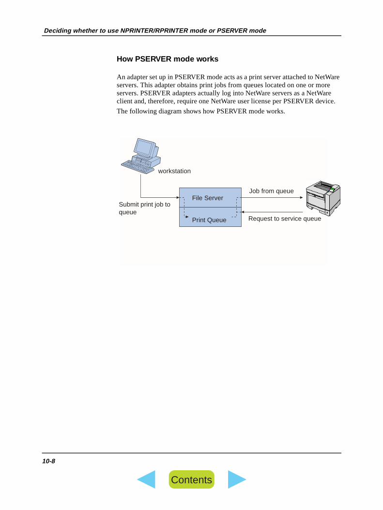
How PSERVER mode works
An adapter set up in PSERVER mode acts as a print server attached to Neservers. This adapter obtains print jobs from queues located on one or moservers. PSERVER adapters actually log into NetWare servers as a NetWaclient and, therefore, require one NetWare user license per PSERVER dev
The following diagram shows how PSERVER mode works.
workstation
Job from queue
Request to service queue
File Server
Print Queue
Submit print job to queue
10-8
Contents

NPRINTER versus PSERVER in IntraNetWare NetWare Directory Services (NDS)
or
lly e
rs in
R
TER
NPRINTER versus PSERVER in IntraNetWare NetWare Directory Services (NDS)
Adapters are fully supported in IntraNetWare NDS, using either NPRINTERPSERVER mode. MarkVision works equally well in both modes. If you usebindery emulation, you cannot use NPRINTER.
NPRINTER mode in IntraNetWare NDS
Advantages of using NPRINTER mode in NDS:
• Does not require a NetWare server user license
• Supports MarkVision fully
Disadvantages of using NPRINTER mode in NDS:
Little information is available about the print job. After a job leaves a print server queue, it is removed from the queue, regardless of whether it actuaprints. This could cause a print job to be lost, if the printer is turned off in thmiddle of the print job. This is inherent in the NetWare design, and is not unique to the Network Adapter.
Notes about printing performance:
For historic reasons, many people prefer to configure their network adaptePSERVER mode. This likely stems from early versions of NetWare, when PSERVER performance was significantly better than NPRINTER/RPRINTEperformance.
This performance difference is less for IntraNetWare. Actual print job throughput is affected by many other factors such as topology, job size andcontent, and network adapter settings. Under many circumstances, NPRINmode provides an excellent IntraNetWare NDS solution.
10-9
Contents

NPRINTER versus PSERVER in IntraNetWare NetWare Directory Services (NDS)
ode
ize
than
ays
s ters
eue a
er rms of
en as
PSERVER mode in IntraNetWare NDS
Advantages of using PSERVER mode in NDS:
• Does not require that PSERVER.NLM be installed on the NetWare server
• Performance. Although overall print job throughput is affected by many factors, file transfer time on the network may be faster using PSERVER mbecause:
• In NPRINTER/RPRINTER mode, NetWare uses SPX to transfer packets. Packet size for data transmitted in SPX is 512 bytes.
• In PSERVER mode, NetWare uses IPX to transfer packets. Packet sfor data transmitted in IPX is up to 1 Kbyte for Ethernet and up to 4 Kbytes for Token-Ring networks.
Because of this difference in packet size, PSERVER mode may be fasterNPRINTER/RPRINTER mode. Please note, however, that actual IPX packet size is negotiated by the client application. This actual IPX packet size is often less than the maximum because of packet size limitations of gatewand routers.
If printing is a significant part of your network traffic, and if network traffic ia proven concern for your network, you may find it better to use the adapin PSERVER mode.
Disadvantage of using PSERVER mode in NDS:
• Requires a NetWare server user license for each PSERVER device
Also, in IntraNetWare you can "pool" printers by assigning a single print quto multiple printers, or "share" printers by assigning multiple print queues tosingle printer. Caution should be exercised when configuring "pooled" printenvironments because the printers need to have the same capabilities in teprinter datastream and resources such as fonts, forms, internal memory, resolution, etc. Though Novell recommends assigning one print queue perprinter for ease of management, it may be useful to "share" a printer betwemultiple queues when a printer supports multiple printer datastreams suchPostScript and PCL emulation.
10-10
Contents

RPRINTER versus PSERVER in NetWare 3.x
lly e
ize
than
ays
s ters
RPRINTER versus PSERVER in NetWare 3.x
Adapters are fully supported in NetWare 3.x, using either RPRINTER or PSERVER mode. MarkVision works equally well in both modes.
RPRINTER mode in NetWare 3.x
Advantages of using RPRINTER mode in NetWare 3.x:
Does not require a NetWare server user license
Disadvantages of using RPRINTER mode in NetWare 3.x:
Little information is available about the print job. After a job leaves a print server queue, it is removed from the queue, regardless of whether it actuaprints. This could cause a print job to be lost, if the printer is turned off in thmiddle of the print job. This is inherent in the NetWare design, and is not unique to Lexmark adapters.
PSERVER mode in NetWare 3.x
Advantages of using PSERVER mode in NetWare 3.x:
• Does not require that PSERVER.NLM be installed on the NetWare server
• Does not require you to unload PSERVER.NLM or reboot your computerafter installation
• Performance. Although overall print job throughput is affected by many factors, file transfer time on the network may be significantly faster using PSERVER mode.
• In NPRINTER/RPRINTER mode, NetWare uses SPX to transfer packets. Packet size for data transmitted in SPX is 512 bytes.
• In PSERVER mode, NetWare uses IPX to transfer packets. Packet sfor data transmitted in IPX is up to 1 Kbyte for Ethernet and up to 4 Kbytes for Token-Ring networks.
Because of this difference in packet size, PSERVER mode may be fasterNPRINTER/RPRINTER mode. Please note, however, that actual IPX packet size is negotiated by the client application. This actual IPX packet size is often less than the maximum because of packet size limitations of gatewand routers.
If printing is a significant part of your network traffic, and if network traffic ia proven concern for your network, you may find it better to use the adapin PSERVER mode.
10-11
Contents

RPRINTER versus PSERVER in NetWare 3.x
Network adapters connect to as many as 16 file servers, with a total of 32 queues per adapter, distributed any way you want among the servers.
Disadvantages of using PSERVER mode in NetWare 3.x:
• Requires a NetWare server user license for each PSERVER device
10-12
Contents

lt is
CHAPTER
11 Apple Talk
Prerequisites 1 Make sure you have physically connected your printer to the network via a network adapter (print server).
Note: You cannot connect this printer directly (locally) to a Macintosh workstation. You must use EtherTalk. There is no serial driver for printers.
2 Make sure AppleTalk protocol is turned on in this adapter. If you are setting up a new adapter this is already done, because the factory defauall protocols turned on.
To turn AppleTalk protocol on or off, use the printer operator panel (or MarkVision for Macintosh).
Configure the adapter and printer
1 Turn the printer power on.
2 Find the new printer in the Chooser.
3 If you want, change the zone of the new printer. The only way to change the zone for an Adapter is to use MarkVision.
4 Change the printer name to a more meaningful name. This is an optional but useful step.
If you are in a LaserWriter 8 environment, follow these steps:
a If you haven't already done so, install MarkVision.
b Launch MarkVision and click VIEW, SELECT ZONES.
c Select the zone that contains the new printer.
d Find the new printer in the list and highlight it.
e To specify the printer name you prefer, click Adapter Settings.
5 Verify that you've renamed the printer. To do this, look in the "Chooser" for the new printer name.
11-1
Contents
Set up a workstation
alk
lex,
er
ld
Set up a workstation
The following steps should be done for each Macintosh user on the AppleTnetwork who wants to use the printer.
1 In the Chooser, highlight the new printer and click the CREATE button.
2 If the system cannot find the appropriate PPD file to associate with the new printer, provide the necessary information yourself. For example, if prompted, specify which options are installed on the printer, such as dupmemory and so forth. Click OK when you are finished.
Note: A PPD file customizes the LaserWriter driver for your particular printmodel.
3 Look for an icon to appear in the "Chooser" next to the printer name. This means a PPD is associated with the network printer. A new desktopprinter icon is placed on your desktop, too.
4 In the Chooser, highlight the printer you want to use now, then close the Chooser window. You are ready to print!
If printer hardware is updated
If you add or change hardware options on the printer (such as paper trays,feeders or duplex), or if you load new paper sizes or types, each user shouupdate his desktop printer object. Follow these steps to update the desktopprinter object:
In a LaserWriter 8 environment (prior to LaserWriter 8.4.1):
1 In the Chooser, highlight the printer to be updated.
2 Click the Setup button.
3 Click Auto Setup to automatically reconfigure the printer options. Or, you can select "Configure" to manually reconfigure the printer options.
In a LaserWriter 8 environment (LaserWriter 8.4.1 and later):
1 Highlight the desktop printer object to be updated.
2 Select the "Printing menu", then select "Change Setup".
3 Select "Auto Setup" to automatically reconfigure the printer options. Or, you can manually reconfigure the printer options if you want.
11-2
Contents

rk ent.
that
ese
CHAPTER
12 Troubleshooting
Commonproblems
If one person is having trouble printing to the network printer, that person's workstation is probably not set up properly to print. If everyone is having trouble printing to the network printer, the problem is more likely the netwoadapter setup. In this case, try using the troubleshooting tips in this docum
The tips are organized by network. See the chart below to find the chapterapplies to you.
TCP/IP If you are having trouble with a Fujitsu adapter on a TCP/IP network, do thsteps in the order shown.
1 Make sure the TCP/IP protocol is turned on (activated) in the adapter. To find out, print an adapter setup page and look in the paragraph underTCP/IP.
To print an adapter setup page, press and release the TEST button.
To turn the TCP/IP protocol on in the Network adapter.
2 Issue a ping command to the adapter. For example, at a DOS command prompt type:
ping 100.220.30.4
where 100.220.30.4 is the TCP/IP address of the adapter.
3 Establish an FTP session with the adapter. For example, at a DOS command prompt type:
ftp 100.220.30.4
where 100.220.30.4 is the TCP/IP address of the adapter. Expect the adapter to return its current firmware level (such as 2.5.15).
4 Using the FTP "put" command, print a file. For example, at the FTP prompt type:
put mytest.ps
Troubleshooting tips for... Chapter
TCP/IP 8
NetWare 10
AppleTalk 11
12-1
Contents

TCP/IP
P/IP
nd
em
where mytest.ps is the file to be printed. This file can be in PostScript, PCL, or any other printer language the printer understands. If the file prints, this confirms the TCP/IP protocol is working properly in the adapter.
5 Check the port settings on the printer object. For example, in Windows 95 do the following:
a Click Start, Settings, Printers, highlight the printer object; click File, Prop-erties, Details tab, Port Settings button.
b Check all parameters on the Adapter Settings tab and the TCP/IP Settings tab. You can change some of the values from this tab. Others, like TCaddress, you cannot change from this tab.
If a parameter is wrong but you cannot change it from here, you mustdelete the port, fix the problem, then add the port back.
6 If you have trouble printing from an application, the problem might be the way your workstation or application is set up. Follow the steps below:
a Try printing from some other application. If the job prints from the secoapplication, you've narrowed the problem down to the first application.
b Make sure you are using the current version of the driver for the problapplication.
7 Try printing to the adapter again.
12-2
Contents

NetWare
e
e the
nd
em
rk.
NetWare If you are having trouble with your adapter on a NetWare network, do thessteps in the order shown.
1 Make sure the NetWare protocol is turned on (activated) in the adapter. To find out, print an adapter setup page and look in the paragraph underNetWare.To print an adapter setup page on the Network Adapter press and releasTEST button on the Network Adapter.
2 If you have trouble printing from an application, the problem might be the way your workstation or application is set up. Follow the steps below:
a Try printing from some other application. If the job prints from the secoapplication, you've narrowed the problem down to the first application.
b Make sure you are using the current version of the driver for the problapplication.
3 Place a job in the queue using a Novell utility, such as NWAdmin or PCONSOLE.
• If the job prints, your adapter is set up properly on the NetWare netwo
12-3
Contents

Network Adapter troubleshooting
al
umber
Network Adapter troubleshooting
The Network Adapter indicates activity, status, and errors by various cyclicpatterns on the four indicator lights.
To more easily describe the various light sequences, we have assigned a nto every possible combination as shown below. The numbers we've chosencorrespond to the binary representation on the indicator lights.
Pattern
binary 0
binary 1
binary 2
binary 3
binary 4
binary 5
binary 6
binary 7
binary 8
binary 9
binary 10
binary 11
binary 12
binary 13
binary 14
binary 15
C 1 2 S
10/100B-T
D
L
S
2
1
C
M T
12-4
Contents

Network Adapter troubleshooting
-
Error conditions
What shows on the four indicator lights Description Cause and solution
binary 12 (for 0.25 sec),binary 3 (for 0.25 sec),repeat continuously.
Serious failure.
The Network Adapter is unable to recover.
Flawed firmware in adapter or power interrup-tion during flash operation.
binary 15 (for 0.25 sec),binary x (for 0.25 sec),repeat continuously.
where x could be 0, 1, 2, 3, 4, 5, 6, 7, 8, or 9
POST error Power-on self test error. During start-up, a hardware failure was detected on the Network Adapter.
What to do:
- Reset the adapter.
12-5
Contents

Network Adapter troubleshooting
12-6
Contents

r
APPENDIX
A Using the printer control panel
Introduction For your convenience, you can view or change some information about theadapter from the control panel of the printer.
You can use the printer control panel to set the IP address, netmask and/ogateway for TCP/IP networks.
A-1
Contents

Introduction
fic
r
n
a
e
IP protocol settings from the printer control panel
1 Turn the printer power On (|).
2 Use the printer control panel to display the network setting menu.
Consult your printer documentation to learn the menu path for your speciprinter, or scroll through the control panel menus until you find it.
You can set the TCP/IP information shown in Table A.1.
3 Press READY to return to ready status.
Table 0.1 IP Protocol
Menu Item Values Description
Enable BOOTP Yes
No
Using this menu item, you can set BOOTP on or off.
You should select No if you have set the IP address, netmask,and/or gateway through the printer’s control panel and you want hese settings to always apply to this adapter.
You should select Yes if you want the adapter to automatically find its BOOTP server to get its IP address, netmask, and/ogateway.
Set
IP Address
IP Address Using this menu item, you can set the IP address directly othe printer’s control panel. When you do, be sure to set Enable BOOTP to No. If Enable BOOTP is set to Yes and you turn the printer off and on again, the adapter will search for BOOTP server and will use the address stored in that file instead of this address. *NOTE
The default IP address is: 0.0.0.0
Set
IP Netmask
IP Netmask Using this menu item, you can set the IP netmask directly through the printer’s control panel. When you do, be sure toset nable BOOTP to No. If Enable BOOTP is set to Yes and you turn the printer off and on again, the adapter will searchfor a BOOTP server and will use the netmask stored in that file instead of this one. *NOTE
The default IP netmask is: 255.255.255.0
Set IP Gateway
IP Gateway Using this menu item, you can set the IP gateway directly through the printer’s control panel. When you do, be sure toset. Enable BOOTP to No. If Enable BOOTP is set to Yes and you turn the printer off and on again, the adapter will searchfor a BOOTP server and will use the gateway stored in that filinstead of this one. *NOTEThe default IP gateway is: 0.0.0.0
A-2
Contents

Introduction
in
is by
Note 1: If you’re not using a boot server you can have the bootp functionthe adapter disabled.
Note 2: If a bootp server becomes available and someone has entered thadapter’s MAC address into the server, then these values are being set bootp, not via the control panel.
A-3
Contents

Introduction
A-4
Contents

e
s an
GLOSSARY
G Glossary
A adapter port. A parallel or serial port located physically on an external network adapter (print server).
address (adapter address). Unique identifier for the network adapter, consisting of 12 hexadecimal digits. Also called physical address, hardwaraddress, or MAC address. See LAA and UAA.
Address Resolution Protocol (ARP). A utility that helps you debug TCP/IP networking problems by letting you display and modify the IP address tophysical address translation tables.
AppleTalk . A network protocol used with Apple computers. Can run on LocalTalk, Ethernet, or Token-Ring.
ARP. See Address Resolution Protocol.
B BOOTP. See BOOTstrap protocol.
BOOTstrap Protocol (BOOTP). A set of client-server utilities and servicethat enables a computer or network device to find its IP address. DHCP is extension of BOOTP.
D Data Link Control Protocol (DLC) . A particular set of rules used by two nodes on a data link to accomplish an orderly exchange of information.
data stream. Print data and control information that flows from the host computer to the printer.
DHCP. See Dynamic Host Configuration Protocol
DLC protocol . See Data Link Control Protocol.
DNS. See Domain Naming Service.
G-1
Contents

E
r S.
t of resses
ion
s,
d
to he
e en -
Domain Naming Service (DNS). A distributed database that provides friendly, hierarchical names for host computers or devices on the Internet oother IP network. DNS is static, and requires more administration than WIN
Dynamic Host Configuration Protocol (DHCP). A set of client-server utilities and services that provides automatic, reliable, dynamic assignmenIP addresses. DHCP ensures that address conflicts are avoided and IP addare allocated efficiently.
E Ethernet. A bus topology that uses carrier sense multiple access with collisdetection (CSMA/CD).
EtherTalk . AppleTalk network protocol running on a Ethernet physical network.
F file server (server). A computer on a network that manages shared printerfiles, and other resources.
File Transfer Protocol (FTP). A TCP/IP utility for transferring files between computers. FTP is a core component in every TCP/IP system, anserves as a common protocol for transferring files between systems.
finger. A TCP/IP utility that provides information about the users logged ona server. When used with a network adapter, finger displays the status of tprinter and current print job.
flash memory. A type of ROM (read-only memory) used on most Fujitsu network adapters. Flash memory can be erased electronically and reprogrammed without your removing the adapter from the printer, or physically going to the adapter.
FTP. See File Transfer Protocol.
G gateway. A device that translates between two networks that do not use thsame communication protocols. A gateway alters packets as necessary, thforwards them to the destination network. A gateway links two or more subnets.
G-2
Contents

I
rint
a
its. in
I INA . See Internal Network Adapter.
Internal Network Adapter (INA) . A device used to connect a single printer in a selected printer family to a network. The INA is a printed circuitcard that installs inside the printer. Also known as print server or internal pserver.
Internetwork Packet Exchange (IPX). A standard networking protocol, used by NetWare and LexIPX.
IPX . See Internetwork Packet Exchange.
L LAA . See Locally Administered Address.
LAN . See local area network.
LAN segment. Any portion of a LAN that operates independently of, but isconnected to, the network by bridges or routers.
line printer daemon (lpd). Half of the TCP/IP remote printing protocol, thissoftware catches the print document that is sent from a host computer. It isbackground process that runs all the time.
local area network (LAN). A computer network located within a limited geographical area.
Locally Administered Address (LAA). An address that a network administrator assigns to a network adapter. Consists of 12 hexadecimal digMany administrators use the LAA to give the adapter a meaningful addresstheir workplace. The LAA is optional. If assigned, it overrides the UAA.
lpd. See line printer daemon.
lpd print service. An AIX or UNIX utility that receives print jobs from remote TCP/IP hosts.
LPT. A representation of one of the logical ports (for example, LPT1) on apersonal computer.
G-3
Contents

M
ss,
t
nter.
ell
rces.
int rk
rk.
ds
M Management Information Base (MIB). A database containing information about network devices (such as adapters, bridges, routers, or computers). This information helps network administrators manage the network (analyze performance, traffic, errors and so forth).
MIB . See Management Information Base.
N NDS. See Novell Directory Services.
netmask. A bit mask that specifies the local network portion of an IP addreallowing you to logically subdivide a network.
network printer . A printer connected to a network by an INA or ENA (prinserver).
nickname. A name that a network administrator gives to the adapter. It canhave various uses, one of which is to identify the type or location of the pri
NLM . Novell NetWare Loadable Module. An optional process used by NovNetWare 3.x and IntraNetWare to add functions to a file server.
Novell Directory Services (NDS). A feature in Novell IntraNetWare that provides centralized management of all NetWare users, servers, and resou
P ping. A utility that helps you debug TCP/IP networking problems by testingwhether a remote device is communicating. Ping verifies connection to a remote host by attempting to receive an echo response.
print server. Hardware or software (or a combination of both) that finds prjobs and forwards them to the appropriate network printer. A Fujitsu netwoadapter (internal or external) is an example of a print server.
protocol. A set of rules governing the communication and transfer of data between two or more devices in a communication system such as a netwo
PSERVER. A Novell NetWare printing service that takes a print job and senit to a printer assigned to a queue.
G-4
Contents

Q
s
ts ess
uter le
.
at
to
s ce on
PSERVER mode. The adapter in PSERVER mode takes the place of the Novell PSERVER process and directs print jobs from a queue to a printer attached to the adapter.
Q queue. A directory on a server's hard disk where print jobs from clients arestored temporarily, until a printer is ready for them.
R RARP. See Reverse Address Resolution Protocol.
requester. A workstation that requests access to shared resources (such aprinters or files) from a server.
Reverse Address Resolution Protocol (RARP). A TCP/IP utility used within a domain for the exchange of routing information. A router broadcaspackets that contain a physical network address. The device with that addrthen returns its IP address.
Router. Hardware that transfers packets between network segments. A rocan read addressing information in a packet and determine the best possibpath for the packet when the network has many different links or pathways
RPRINTER . A terminate-and-stay-resident (TSR) program that runs on aNovell workstation. This program allows a printer attached to a local workstation to be used as a shared network printer.
RPRINTER mode. The adapter in RPRINTER mode emulates the TSR thwould normally run on the Novell workstation. The adapter in RPRINTER mode is used in conjunction with Novell PSERVER utility to direct print jobsa printer attached to the adapter. This method does not use a Netware connection.
S SAP. See Service Advertising Protocol.
server. See file server.
Service Advertising Protocol (SAP). Used by Fujitsu network adapters (awell as NetWare servers and routers) to periodically broadcast their presenthe NetWare network, and advertise what services they can provide.
G-5
Contents

T
ice
al
ress. sign
ry han
SNMP. See Simple Network Management Protocol.
source routing. A Token-Ring function that allows data to pass from one Token-Ring network across Token-Ring bridges to another Token-Ring network. If source routing is disabled, packets will not cross source-routingbridges.
spooler. An intercepting program that receives and disseminates print jobs(usually from many sources) in an orderly manner.
T telnet. A TCP/IP utility that lets you interact with a remote computer or devvia terminal emulation. You can display and set parameters for a Lexmark network adapter by using the command:
telnet IP_address 9000
tftp . See Trivial File Transfer Protocol.
Trivial File Transfer Protocol (tftp) . A stripped-down version of FTP. It does not list directories or authenticate users, but only transfer files. Minimoverhead but no guarantee of delivery.
U UAA . See Universally Administered Address.
Universally Administered Address (UAA). The unique address that Lexmark assigns to a network adapter. It is the factory-default adapter addConsists of 12 hexadecimal digits. If the network administrator does not asan LAA, the UAA is used as the adapter address.
W WINS. See Windows Internet Naming Service.
Windows Internet Naming Service (WINS). Software that maintains a dynamic database for hostname-to-IP-address resolution on medium to velarge IP networks. Dramatically reduces IP broadcast traffic. More flexible tDNS.
Z zone. In AppleTalk, the grouping of network devices in a logical manner sothat they may be easily accessed by the user.
G-6
Contents