pacific gas and electric gas safety plan september
TRANSCRIPT
PACIFIC GAS AND ELECTRIC
GAS SAFETY PLAN
SEPTEMBER 30, 2014 REVISION 2
GP-1000
PACIFIC GAS AND ELECTRIC COMPANY GAS SAFETY PLAN
GP-1000 REVISION 2
TABLE OF CONTENTS
List of Acronyms ........................................................................................................................ iv List of Figures ............................................................................................................................. v List of Tables .............................................................................................................................. v List of Attachments .................................................................................................................... vi
I. Introduction and Regulatory Summary .......................................................................... 1 A. PG&E’s Adherence to SB 705 (PUC §§ 961 and 963) ................................................3
1. Gas Safety Executive Committee .........................................................................4 2. Gas Safety Plan Team.........................................................................................4
B. PG&E’s Safety Culture and Goals ...............................................................................5 C. Gas Safety Excellence ................................................................................................6
II. Achieving Safety through Asset Management ............................................................11 A. Publicly Available Specification (PAS) 55 and International Organization for
Standardization (ISO 55001).....................................................................................11 B. Risk Management Process .......................................................................................12
1. Enterprise and Operational Risk Management ...................................................12 2. Asset Family Structure.......................................................................................15
a. Transmission Pipe ......................................................................................16 b. Distribution Mains and Services ..................................................................18 c. Gas Storage................................................................................................18 d. Compression & Processing .........................................................................19 e. Measurement & Control ..............................................................................20 f. Customer Connection Equipment................................................................20 g. Compressed Natural Gas/Liquefied Natural Gas .........................................20
3. Understanding Risks to the Asset Families ........................................................ 21 a. Risk Framework ..........................................................................................21 b. Risk Register ..............................................................................................23
4. Mitigation Programs to Reduce Risk ..................................................................25 a. Mitigating Loss of Containment ...................................................................25
a) Damage Prevention .............................................................................25 Public Awareness ..........................................................................25 I)
II) Dig-In Prevention ..........................................................................26 Locate and Mark ...........................................................................27 III)
b) Distribution Pipeline Replacement........................................................27 c) Cross-Bore Mitigation...........................................................................28 a) Hydrostatic Strength Testing ................................................................28 b) Vintage Pipeline Replacement .............................................................30 c) In-Line Inspection Retrofitting ...............................................................31 d) Corrosion Program...............................................................................31 e) Earthquake Fault Crossings .................................................................32 f) Leak Survey .........................................................................................33 g) Leak Repair..........................................................................................34 h) Pipeline Patrol and Monitoring .............................................................35
I) Pipeline Markers ...........................................................................36 II) Pipeline Pathways.........................................................................37
-i
PACIFIC GAS AND ELECTRIC COMPANY GAS SAFETY PLAN
GP-1000 REVISION 2
TABLE OF CONTENTS (CONTINUED)
i) Cyber Security .....................................................................................38 b. Mitigating Loss of Supply ............................................................................38
a) System Pressure and Capacity ............................................................38 b) Overpressure Elimination Initiative .......................................................40 c) Operations Clearance Procedures .......................................................40 d) Supplier Quality for Distribution and Transmission Gas Products.........41
c. Mitigating Inadequate Response and Recovery ..........................................42 a) Gas System Operations and Control ....................................................43
Transmission Control Center .........................................................44 I) Distribution Control Center ............................................................44 II)
b) Enhancements to Transmission and Distribution Control Centers ........45 c) Valve Automation.................................................................................45 d) Emergency Response..........................................................................46
I) Company Emergency Plan ............................................................ 46 II) Gas Emergency Preparedness and Response ..............................48 III) Earthquake Response...................................................................49 IV) Information for First Responders and the Public ............................50
Call Center ....................................................................................50 V) VI) Response to Customer Odor Calls ................................................50
C. Compliance ...............................................................................................................50 1. Codes, Standards, Policies, and Procedures .....................................................50
a. Code Compliance .......................................................................................52 a) Maximum Allowable Operating Pressure ..............................................53 b) Class Location .....................................................................................53 c) Design..................................................................................................54 d) Construction .........................................................................................55 e) Installation ............................................................................................55 f) Maintenance ........................................................................................55 g) Operations ...........................................................................................55 h) Odorization ..........................................................................................56
2. Records Quality and Information Management ..................................................56 D. Continuous Improvement ..........................................................................................58
1. Quality Assurance and Quality Control...............................................................58 2. Research and Development ...............................................................................59 3. Leak Optimization Pilot (Super Crew) ................................................................59 4. Benchmarking and Best Practices ..................................................................... 59
a. Standards Written by Subject Matter Experts ..............................................60 b. Agency Publications ....................................................................................61 c. Peer Associations .......................................................................................61
a) American Gas Association ...................................................................61 b) Interstate Natural Gas Association of America .....................................62 c) NACE International ..............................................................................63 d) Western Energy Institute ......................................................................63
E. Employee Workforce and Training ............................................................................63 1. Workforce Size ..................................................................................................63 2. Employee Training .............................................................................................65
-ii
PACIFIC GAS AND ELECTRIC COMPANY GAS SAFETY PLAN
GP-1000 REVISION 2
TABLE OF CONTENTS (CONTINUED)
3. Operator Qualifications ......................................................................................66 4. Contractor Safety, Training, and Oversight ........................................................68 5. Partnership With Local Unions ...........................................................................69
III. PG&E’s Safety Culture ..................................................................................................70 A. PG&E’s Corporate Safety Committees......................................................................70 B. Employee Engagement .............................................................................................71
1. Corrective Action Program .................................................................................72 2. Compliance and Ethics Helpline.........................................................................73 3. Material Problem Reporting ...............................................................................74 4. Grassroots Safety Teams ..................................................................................74 5. Near Hits Reporting ...........................................................................................74
IV. Process Safety...............................................................................................................75
V. Conclusion ..................................................................................................................... 80
VI. Signatures ...................................................................................................................... 81
-iii
PACIFIC GAS AND ELECTRIC COMPANY GAS SAFETY PLAN
GP-1000 REVISION 2
TABLE OF CONTENTS (CONTINUED)
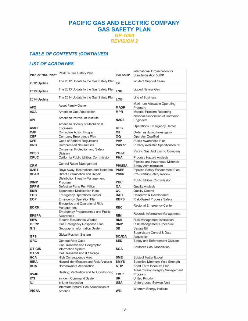
LIST OF ACRONYMS
Plan or "the Plan"
2012 Update
2013 Update
2014 Update
AFO AGA
API
ASME CAP CEP CFR CNG
CPSD CPUC
CRM DART DE&R
DIMP DPPM EMR EOC EOP
EORM
EP&PA ERW GERP GIS
GPS GRC
GT GIS GT&S HCA HIRA HOA
HVAC ICS ILI
INGAA
PG&E's Gas Safety Plan
The 2012 Update to the Gas Safety Plan
The 2013 Update to the Gas Safety Plan
The 2014 Update to the Gas Safety Plan
Asset Family Owner
American Gas Association
American Petroleum Institute
American Society of Mechanical Engineers Corrective Action Program Company Emergency Plan Code of Federal Regulations Compressed Natural Gas Consumer Protection and Safety Division California Public Utilities Commission
Control Room Management
Days Away, Restrictions and Transfers Direct Examination and Repair Distribution Integrity Management Program Defective Parts Per Million Experience Modification Rate Emergency Operations Center Emergency Operation Plan Enterprise and Operational Risk Management Emergency Preparedness and Public Awareness Electric Resistance Welded Gas Emergency Response Plan Geographic Information System
Global Position System
General Rate Case Gas Transmission Geographic Information System Gas Transmission & Storage High Consequence Area Hazard Identification and Risk Analysis Homeowners Association
Heating, Ventilation and Air Conditioning
Incident Command System In-Line Inspection Interstate Natural Gas Association of America
ISO 55001
IST
LNG
LOB
MAOP MPR
NACE
OEC OII OQ PAP PAS 55
PG&E PHA
PHMSA PSEP PSSR
PUC QA QC R&D RBPS
REC
RIM RMI RMP SB
SCADA SED
SGA
SME SMYS STIP
TIMP UK USA
WEI
International Organization for Standardization 55001
Incident Support Team
Liqued Natural Gas
Line of Business
Maximum Allowable Operating Pressure Material Problem Reporting National Association of Corrosion Engineers
Operations Emergency Center
Order Instituting Investigation Operator Qualified Public Awareness Plan Publicly Available Specification 55
Pacific Gas And Elecric Company
Process Hazard Analysis Pipeline and Hazardous Materials Safety Administration Pipeline Safety Enhancment Plan Pre-Startup Safety Review
Public Utilities Commission
Quality Analysis Quality Control Research & Development Risk-Based Process Safety
Regional Emergency Center
Records Informaiton Management
Risk Management Instruction Risk Management Procedure Senate Bill Supervisory Control & Data Acquisition Safety and Enforcement Division
Southern Gas Association
Subject Matter Expert Specified Minimum Yield Strength Short Term Incentive Plan Transmission Integrity Management Program United Kingdom Underground Service Alert
Western Energy Institute
-iv
PACIFIC GAS AND ELECTRIC COMPANY GAS SAFETY PLAN
GP-1000 REVISION 2
TABLE OF CONTENTS (CONTINUED)
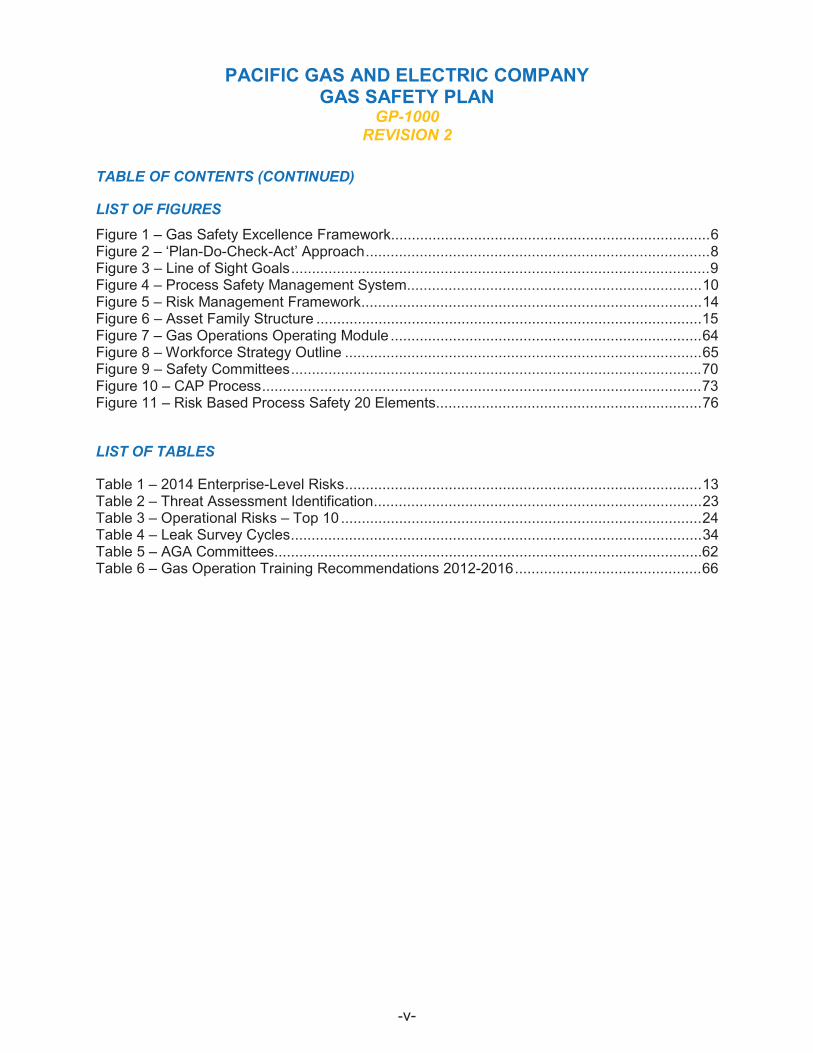
LIST OF FIGURES Figure 1 – Gas Safety Excellence Framework.............................................................................6 Figure 2 – ‘Plan-Do-Check-Act’ Approach...................................................................................8 Figure 3 – Line of Sight Goals..................................................................................................... 9 Figure 4 – Process Safety Management System .......................................................................10 Figure 5 – Risk Management Framework..................................................................................14 Figure 6 – Asset Family Structure ............................................................................................. 15 Figure 7 – Gas Operations Operating Module ...........................................................................64 Figure 8 – Workforce Strategy Outline ......................................................................................65 Figure 9 – Safety Committees................................................................................................... 70 Figure 10 – CAP Process .......................................................................................................... 73 Figure 11 – Risk Based Process Safety 20 Elements ................................................................76
LIST OF TABLES
Table 1 – 2014 Enterprise-Level Risks ......................................................................................13 Table 2 – Threat Assessment Identification ...............................................................................23 Table 3 – Operational Risks – Top 10 .......................................................................................24 Table 4 – Leak Survey Cycles...................................................................................................34 Table 5 – AGA Committees....................................................................................................... 62 Table 6 – Gas Operation Training Recommendations 2012-2016............................................. 66
-v

PACIFIC GAS AND ELECTRIC COMPANY GAS SAFETY PLAN
GP-1000 REVISION 2
TABLE OF CONTENTS (CONTINUED)
LIST OF ATTACHMENTS
Attachment 1 – Asset Management Strategy and Objectives ....................................................15 Attachment 2 – Transmission Management Plan ......................................................................17 Attachment 3 – Gas Distribution Mains and Services................................................................18 Attachment 4 – Gas Storage..................................................................................................... 19 Attachment 5 – Compression & Processing ..............................................................................19 Attachment 6 – Measurement & Control....................................................................................20 Attachment 7 – Customer Connection Equipment .....................................................................20 Attachment 8 – LNG and CNG Potable Supplies ......................................................................21 Attachment 9 – CNG Station Fueling ........................................................................................21 Attachment 10 – Public Awareness Plan - RMP-12...................................................................25 Attachment 11 – 2014 Company Emergency Plan .................................................................... 46 Attachment 12 – GERP............................................................................................................. 48 Attachment 13 – RMI-04 ........................................................................................................... 49 Attachment 14 – RMI-04B......................................................................................................... 49 Attachment 15 – Earthquake Playbook EMER-1012 ................................................................. 49 Attachment 16 – Gas Technical Teams ....................................................................................52 Attachment 17 – CPUC Reports ...............................................................................................53 Attachment 18 – NOS Charter ..................................................................................................70 Attachment 19 – Chairman's Safety Council Charter.................................................................70 Attachment 20 – Gas Ops Risk Compliance Committee ...........................................................71 Attachment 21 – Cap Risk Assessment Tool ............................................................................72 Attachment 22 – Cap Work Flow Chart .....................................................................................72 Attachment 23 – Compliance and Ethics - Priority A Response Procedure ...............................73
-vi
PACIFIC GAS AND ELECTRIC COMPANY GAS SAFETY PLAN
GP-1000 REVISION 2
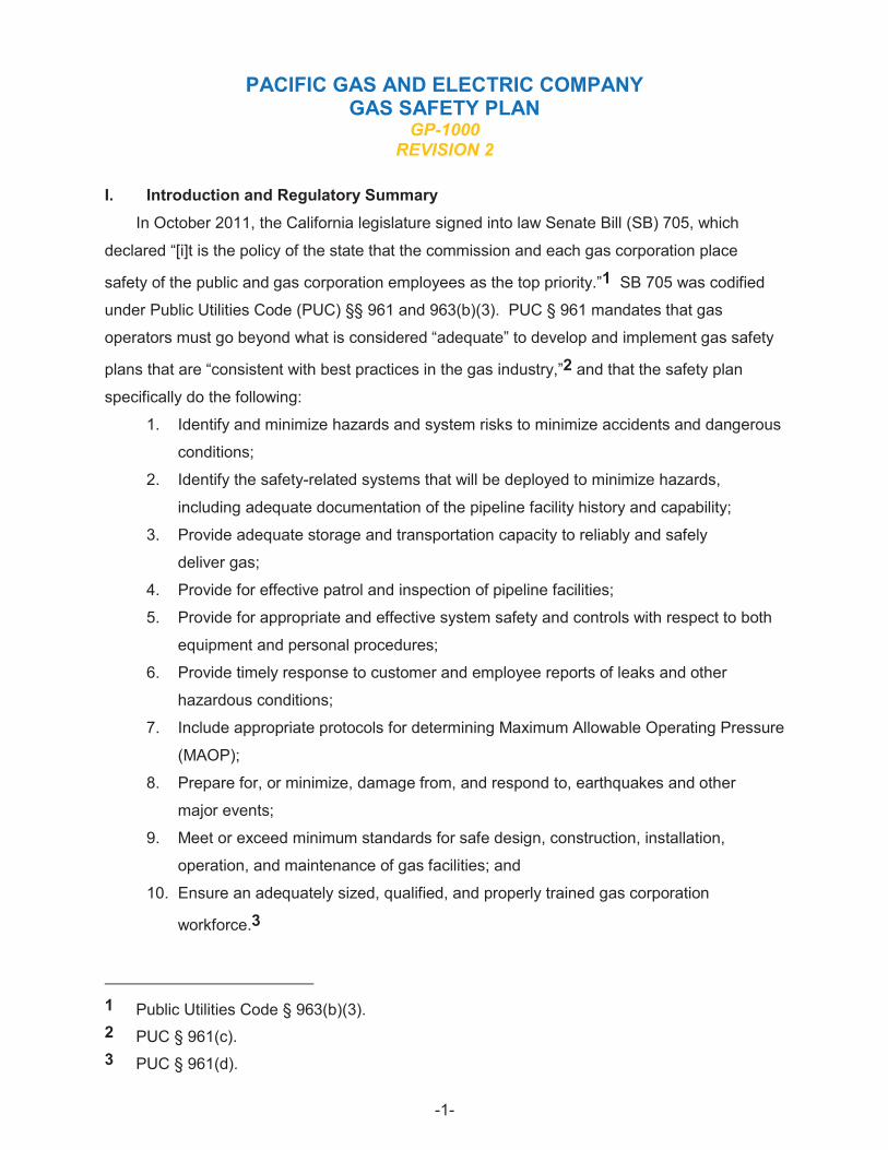
I. Introduction and Regulatory Summary In October 2011, the California legislature signed into law Senate Bill (SB) 705, which
declared “[i]t is the policy of the state that the commission and each gas corporation place
safety of the public and gas corporation employees as the top priority.”1 SB 705 was codified
under Public Utilities Code (PUC) §§ 961 and 963(b)(3). PUC § 961 mandates that gas
operators must go beyond what is considered “adequate” to develop and implement gas safety
plans that are “consistent with best practices in the gas industry,”2 and that the safety plan
specifically do the following:
1. Identify and minimize hazards and system risks to minimize accidents and dangerous
conditions;
2. Identify the safety-related systems that will be deployed to minimize hazards,
including adequate documentation of the pipeline facility history and capability;
3. Provide adequate storage and transportation capacity to reliably and safely
deliver gas;
4. Provide for effective patrol and inspection of pipeline facilities;
5. Provide for appropriate and effective system safety and controls with respect to both
equipment and personal procedures;
6. Provide timely response to customer and employee reports of leaks and other
hazardous conditions;
7. Include appropriate protocols for determining Maximum Allowable Operating Pressure
(MAOP);
8. Prepare for, or minimize, damage from, and respond to, earthquakes and other
major events;
9. Meet or exceed minimum standards for safe design, construction, installation,
operation, and maintenance of gas facilities; and
10. Ensure an adequately sized, qualified, and properly trained gas corporation
workforce.3
1 Public Utilities Code § 963(b)(3). 2 PUC § 961(c). 3 PUC § 961(d).
-1
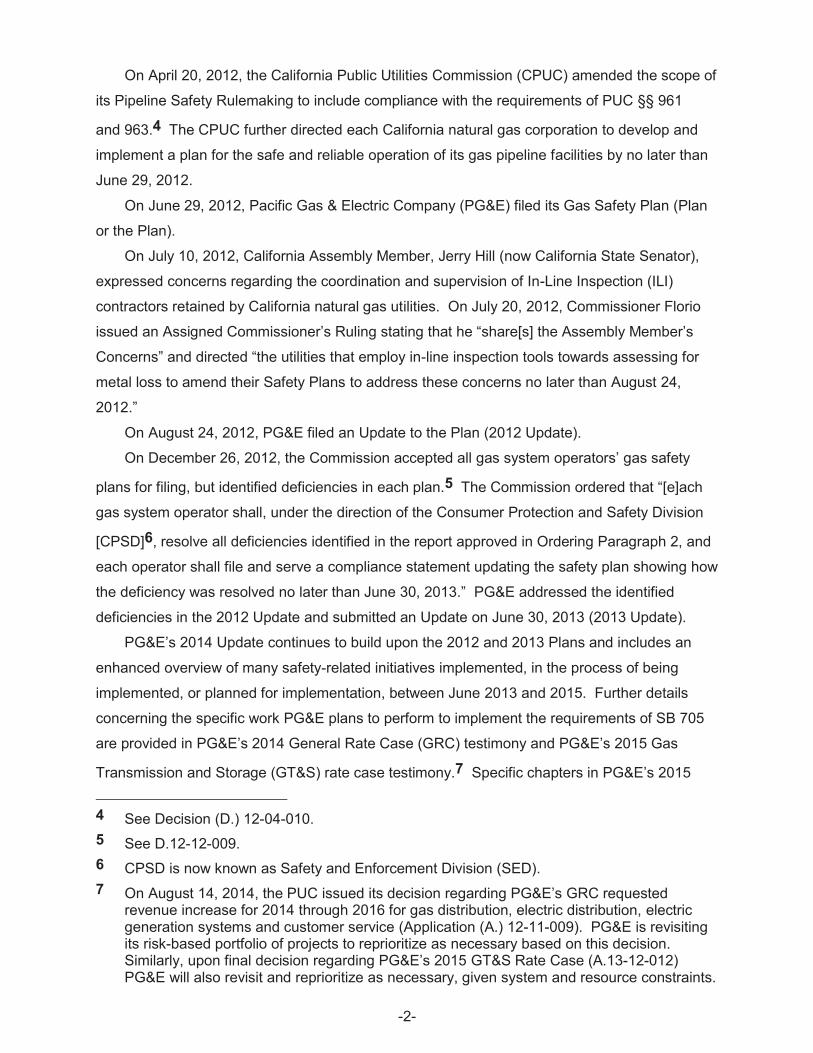
On April 20, 2012, the California Public Utilities Commission (CPUC) amended the scope of
its Pipeline Safety Rulemaking to include compliance with the requirements of PUC §§ 961
and 963.4 The CPUC further directed each California natural gas corporation to develop and
implement a plan for the safe and reliable operation of its gas pipeline facilities by no later than
June 29, 2012.
On June 29, 2012, Pacific Gas & Electric Company (PG&E) filed its Gas Safety Plan (Plan
or the Plan).
On July 10, 2012, California Assembly Member, Jerry Hill (now California State Senator),
expressed concerns regarding the coordination and supervision of In-Line Inspection (ILI)
contractors retained by California natural gas utilities. On July 20, 2012, Commissioner Florio
issued an Assigned Commissioner’s Ruling stating that he “share[s] the Assembly Member’s
Concerns” and directed “the utilities that employ in-line inspection tools towards assessing for
metal loss to amend their Safety Plans to address these concerns no later than August 24,
2012.”
On August 24, 2012, PG&E filed an Update to the Plan (2012 Update).
On December 26, 2012, the Commission accepted all gas system operators’ gas safety
plans for filing, but identified deficiencies in each plan.5 The Commission ordered that “[e]ach
gas system operator shall, under the direction of the Consumer Protection and Safety Division
[CPSD]6, resolve all deficiencies identified in the report approved in Ordering Paragraph 2, and
each operator shall file and serve a compliance statement updating the safety plan showing how
the deficiency was resolved no later than June 30, 2013.” PG&E addressed the identified
deficiencies in the 2012 Update and submitted an Update on June 30, 2013 (2013 Update).
PG&E’s 2014 Update continues to build upon the 2012 and 2013 Plans and includes an
enhanced overview of many safety-related initiatives implemented, in the process of being
implemented, or planned for implementation, between June 2013 and 2015. Further details
concerning the specific work PG&E plans to perform to implement the requirements of SB 705
are provided in PG&E’s 2014 General Rate Case (GRC) testimony and PG&E’s 2015 Gas
Transmission and Storage (GT&S) rate case testimony.7 Specific chapters in PG&E’s 2015
4 See Decision (D.) 12-04-010. 5 See D.12-12-009. 6 CPSD is now known as Safety and Enforcement Division (SED). 7 On August 14, 2014, the PUC issued its decision regarding PG&E’s GRC requested
revenue increase for 2014 through 2016 for gas distribution, electric distribution, electric generation systems and customer service (Application (A.) 12-11-009). PG&E is revisiting its risk-based portfolio of projects to reprioritize as necessary based on this decision. Similarly, upon final decision regarding PG&E’s 2015 GT&S Rate Case (A.13-12-012) PG&E will also revisit and reprioritize as necessary, given system and resource constraints.
-2
GT&S rate case are referred to throughout this Update. The 2015 GT&S rate case describes
forward looking programs that will continue to enhance safety with emphasis on continuous
improvement.
The 2014 Update reiterates PG&E’s commitment and vision to become the safest, most
reliable natural gas system in the nation. This vision will be achieved through the Gas Safety
Excellence framework. The strategy is to deliver Gas Safety Excellence by putting safety and
people at the heart of everything; investing in the reliability and integrity of our gas system; and
by continuously improving the effectiveness and affordability of our processes. Strategic actions
developed under this strategy are aligned under three elements of a safety management system
that: (1) develop an asset management strategy to appropriately invest in the integrity and
reliability of the gas system; (2) nurture a safety-first culture that places safety at the heart of
everything it does; and (3) focus on process safety in all activities to minimize the possibility of
high consequence events.
PG&E remains steadfast in its vision and commitment to becoming the safest, most reliable
gas company in the nation. Strategic actions developed under Gas Safety Excellence include:
(1) eliminating public safety related incidents; (2) being in the 1st quartile for employee and
contractor safety and eliminating serious injuries; (3) meeting all reliability commitments, such
as reducing unplanned outages; (4) meeting customer commitments and being in the
1st quartile for customer satisfaction; (5) being in the 1st quartile for employee engagement;
and, (6) meeting all regulatory commitments. These items are discussed in more detail
throughout this Update.
PG&E’s vision is in alignment with the adopted safety policy of the CPUC issued on July 14,
2014, which declares the CPUC is “…striving to achieve a goal of zero accidents and injuries
across all the utilities and businesses [they] regulate, and within [their] own workplace.”8 The
intent of PG&E’s Plan is to provide an overarching safety strategy and framework that ensures
alignment and continued improvement relative to best practices and its vision. PG&E’s Plan
connects the dots between all of PG&E’s efforts to ensure the safety of the gas system, the
public, and employees and contractors.
A. PG&E’s Adherence to SB 705 (PUC §§ 961 and 963) To ensure PG&E is implementing and continuously maintaining the Plan, a Gas Safety
Executive Committee, and a Gas Safety Team (both described below) will review and update
the Plan once per year, not to exceed 15 months. Updated versions of the Plan will be shared
See July 10, 2014, Safety Policy Statement adopted by the Commission at www.cpuc.ca.gov/NR/rdonlyres/967047D4-19CE-45B1-8766057F1D7FF1CD/0/VisionZero4Final621014_5_2.pdf.
-3
8
with the CPUC annually, unless otherwise directed by the CPUC. Further, all employees and
contractors have access to the Plan, and the opportunity to comment on the Plan via PG&E’s
Corrective Action Program (CAP) (discussed in Section III.B.1).
1. Gas Safety Executive Committee The Gas Safety Executive Committee is responsible for allocating the necessary resources
to support the development, implementation, and maintenance of the Plan and its components.
The Executive Committee is not a formal committee, but includes all Sr. Leadership at PG&E,
who are responsible for approving and signing the Plan. The Executive Committee includes the
following members:
x Executive Vice President, Gas Operations
x Sr. Vice President, Safety and Shared Services
x Sr. Vice President, Engineering, Construction, and Operations
x Vice President, Major Projects and Programs
x Vice President, Gas Transmission and Distribution Operations
x Vice President, Gas Engineering and Design
x Vice President, Asset and Risk Management
x Vice President, Financial and Resource Management
x Senior Director, Gas Transmission and Distribution Construction
x Senior Director, Gas Systems Operations
x Senior Director, Asset Knowledge & Integrity Management
x Senior Director, Gas Regulatory Strategist
x Senior Director, Field Operations
x Senior Director, Strategy and Process Excellence
2. Gas Safety Plan Team The Gas Safety Plan Team is responsible for ensuring that the Plan reflects all components
accurately and in a timely manner, including managing processes to ensure updates to any
component of the Plan. The team is responsible for ensuring the Plan is reviewed and
approved. This team is also responsible for ensuring appropriate communications to employees
about the Plan and ensuring the Plan is available to all employees and contractors. Gas Safety
Team in not a formal team, but includes representatives from the following organizations who
provide insights to the information included in the Plan:
-4
x Distribution Integrity Management x Regulatory Compliance
x Transmission Integrity Management x Emergency Response
x Codes, Standards and Procedures x Regulatory Strategy
x Engineering & Design x Asset Knowledge
x Gas Control x Maintenance and Construction
x Field Service x Technology, Strategy & Solutions
x Training x Local Unions
x Quality Assurance and Quality Control x Mapping
B. PG&E’s Safety Culture and Goals PG&E recognizes that building and maintaining a safety-first culture takes time and
continued commitment. PG&E is committed to sustaining a strong safety culture. Employees
are encouraged to report and act on safety concerns, which further fosters an environment of
accountability and ownership where significant and essential behavioral changes can occur at
all levels. PG&E’s focus is to nurture a culture based on trust where employees feel
comfortable speaking up, stopping jobs, sharing incidents or near hits, and learning from one
another – without discipline or fear of reprisal. Additionally, PG&E is focused on reinforcing
clearly defined goals and expectations, structuring incentives to align with those goals,
measuring progress using industry benchmarks, and effectively communicating with customers,
regulators, and the communities it serves.
Performance goals are a driving force behind management decisions and allocation of
resources. In 2012, PG&E revised its performance goals and a portion of its compensation
(known as the Short-Term Incentive Plan – STIP) for non-represented employees. Safety is
now the single largest factor in the performance goals representing 40 percent of the total. The
remaining two factors - customer satisfaction and financial performance - are weighted 35 and
25 percent, respectively.9 This change reinforced the importance of safety.
PG&E’s 2014 STIP goals include several measures based on safety performance,
customer satisfaction, and gas and electric reliability. The safety measures, which align with
how PG&E will achieve its vision to become the safest, most reliable gas utility in the nation,
include metrics for customer odor call response, leak repairs, gas emergency response,
employee injuries, and preventable motor vehicle accidents. Customer goals are based on
2014 weighted goals are 40% Safety, 35% Customer, and 25% Financial. In 2013, the weighted totals were: 40% Safety, 30% Customer, and 30% Financial.
-5
9
customer satisfaction, which includes – among other measures – customer survey results, gas
asset mapping duration,10 ILIs index,11 and gas reliability.12
PG&E has also established safety leadership training that is, instructor led and focused on
further ingraining the safety culture in its employees. This training articulates the strategy to
continue to enhance the safety culture and helps leaders apply the elements that will allow them
to succeed and to lead with safety by identifying the actions they will need to take to improve the
safety climate at PG&E.
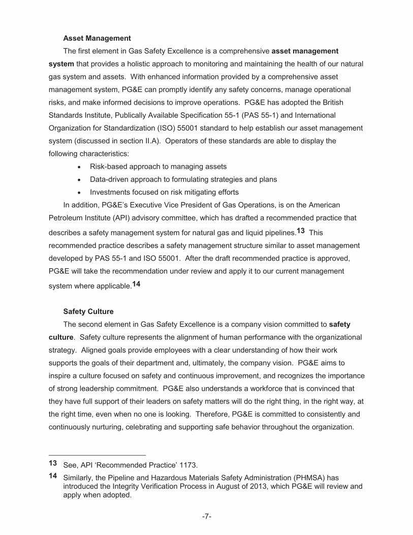
C. Gas Safety Excellence Gas Safety Excellence is PG&E’s Gas Operation’s strategic framework to achieve the
vision of becoming the safest, most reliable gas company in the nation. This framework is
designed to improve safety, manage risk, and drive continuous improvement.
The Gas Safety Excellence strategy is:
x Putting safety and people at the heart of everything
x Investing in the reliability and integrity of our gas system
x Continuously improving the effectiveness and affordability of our processes
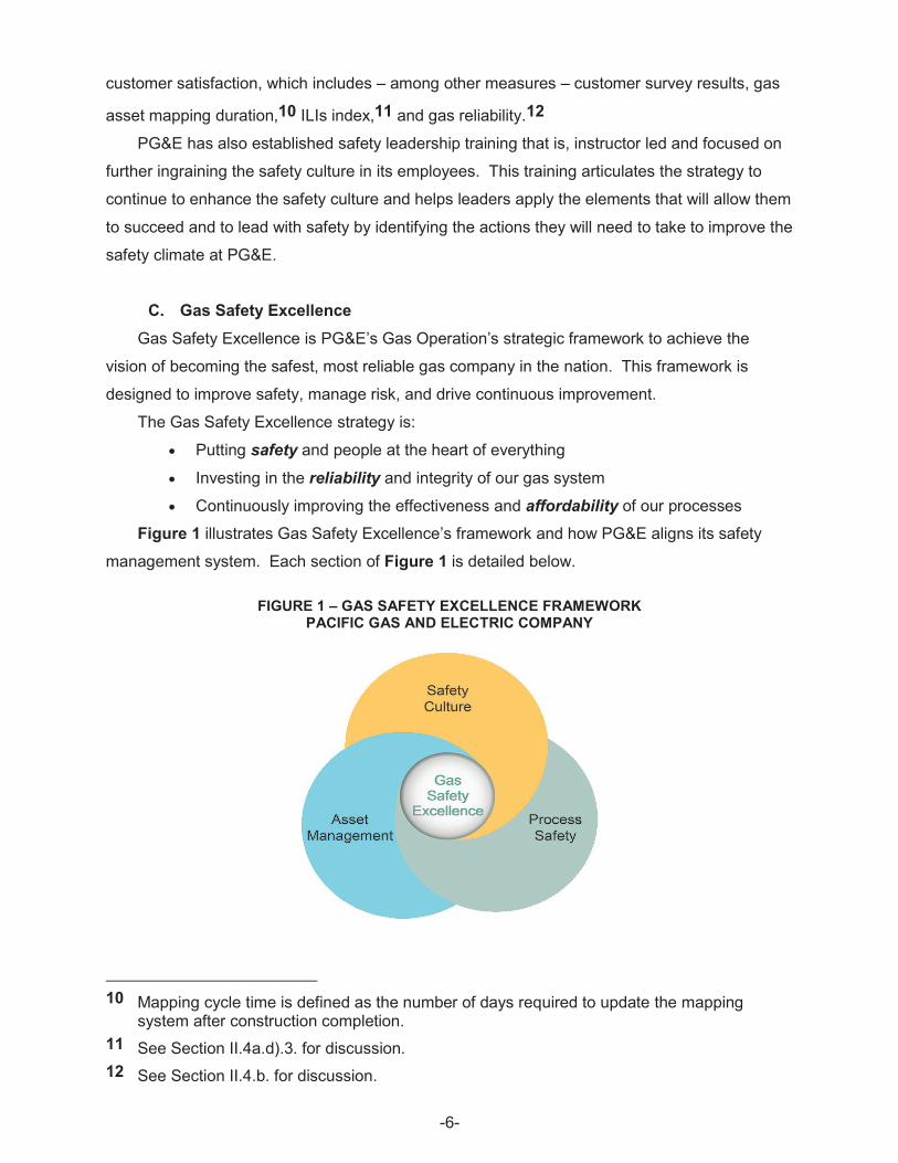
Figure 1 illustrates Gas Safety Excellence’s framework and how PG&E aligns its safety
management system. Each section of Figure 1 is detailed below.
FIGURE 1 – GAS SAFETY EXCELLENCE FRAMEWORK PACIFIC GAS AND ELECTRIC COMPANY
10 Mapping cycle time is defined as the number of days required to update the mapping system after construction completion.
11 See Section II.4a.d).3. for discussion. 12 See Section II.4.b. for discussion.
-6
Asset Management The first element in Gas Safety Excellence is a comprehensive asset management
system that provides a holistic approach to monitoring and maintaining the health of our natural
gas system and assets. With enhanced information provided by a comprehensive asset
management system, PG&E can promptly identify any safety concerns, manage operational
risks, and make informed decisions to improve operations. PG&E has adopted the British
Standards Institute, Publically Available Specification 55-1 (PAS 55-1) and International
Organization for Standardization (ISO) 55001 standard to help establish our asset management
system (discussed in section II.A). Operators of these standards are able to display the
following characteristics:
x Risk-based approach to managing assets
x Data-driven approach to formulating strategies and plans
x Investments focused on risk mitigating efforts
In addition, PG&E’s Executive Vice President of Gas Operations, is on the American
Petroleum Institute (API) advisory committee, which has drafted a recommended practice that
describes a safety management system for natural gas and liquid pipelines.13 This
recommended practice describes a safety management structure similar to asset management
developed by PAS 55-1 and ISO 55001. After the draft recommended practice is approved,
PG&E will take the recommendation under review and apply it to our current management
system where applicable.14
Safety Culture The second element in Gas Safety Excellence is a company vision committed to safety
culture. Safety culture represents the alignment of human performance with the organizational
strategy. Aligned goals provide employees with a clear understanding of how their work
supports the goals of their department and, ultimately, the company vision. PG&E aims to
inspire a culture focused on safety and continuous improvement, and recognizes the importance
of strong leadership commitment. PG&E also understands a workforce that is convinced that
they have full support of their leaders on safety matters will do the right thing, in the right way, at
the right time, even when no one is looking. Therefore, PG&E is committed to consistently and
continuously nurturing, celebrating and supporting safe behavior throughout the organization.
13 See, API ‘Recommended Practice’ 1173. 14 Similarly, the Pipeline and Hazardous Materials Safety Administration (PHMSA) has
introduced the Integrity Verification Process in August of 2013, which PG&E will review and apply when adopted.
-7
To demonstrate its continued progress in achieving Gas Safety Excellence, PG&E worked
diligently and achieved both globally recognized certifications in 2014 – PAS 55-1 and
ISO 55001. In fact, PG&E is one of the first utilities in the United States to receive these types
of certifications, which is awarded by an independent, third-party auditor.
Standards provided in PAS 55-1 and ISO 55001 offer many benefits to PG&E’s Gas
Operations. Attaining these certifications demonstrate that PG&E’s Gas Operations has an
integrated, standard-based level of maturity, from which PG&E can build upon and improve.
Other benefits include a decision-making process for PG&E assets, which promotes better
development of mitigation strategies for all stages of the assets lifecycle.
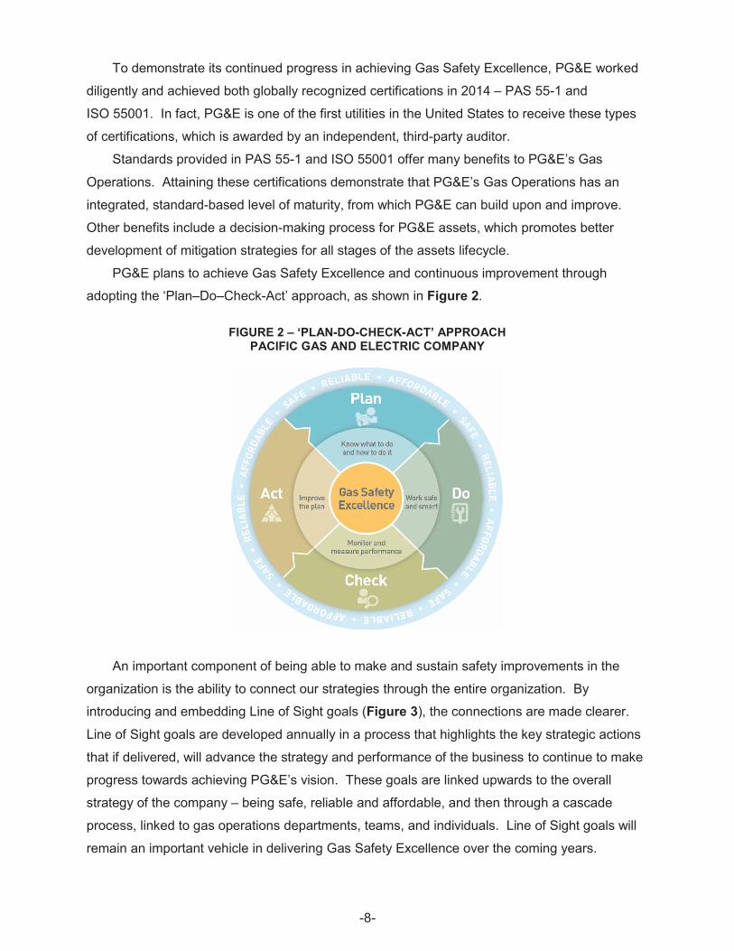
PG&E plans to achieve Gas Safety Excellence and continuous improvement through
adopting the ‘Plan–Do–Check-Act’ approach, as shown in Figure 2.
FIGURE 2 – ‘PLAN-DO-CHECK-ACT’ APPROACH PACIFIC GAS AND ELECTRIC COMPANY
An important component of being able to make and sustain safety improvements in the
organization is the ability to connect our strategies through the entire organization. By
introducing and embedding Line of Sight goals (Figure 3), the connections are made clearer.
Line of Sight goals are developed annually in a process that highlights the key strategic actions
that if delivered, will advance the strategy and performance of the business to continue to make
progress towards achieving PG&E’s vision. These goals are linked upwards to the overall
strategy of the company – being safe, reliable and affordable, and then through a cascade
process, linked to gas operations departments, teams, and individuals. Line of Sight goals will
remain an important vehicle in delivering Gas Safety Excellence over the coming years.
-8
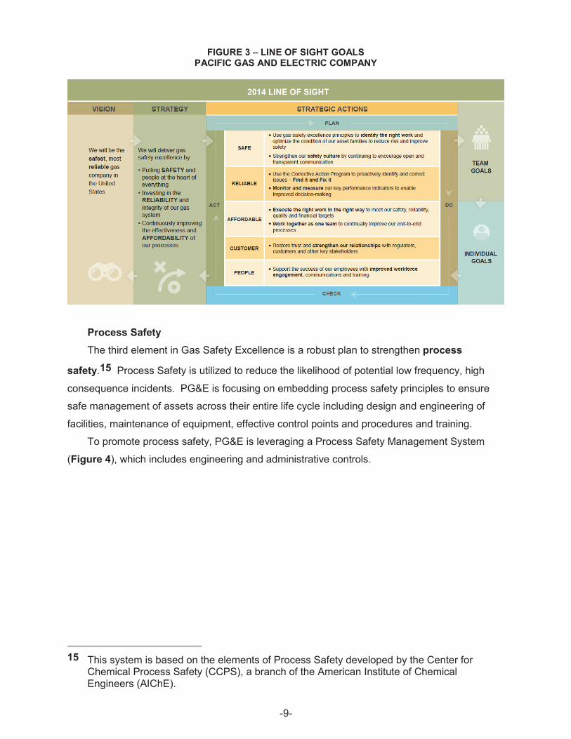
FIGURE 3 – LINE OF SIGHT GOALS PACIFIC GAS AND ELECTRIC COMPANY
Process Safety The third element in Gas Safety Excellence is a robust plan to strengthen process
safety.15 Process Safety is utilized to reduce the likelihood of potential low frequency, high
consequence incidents. PG&E is focusing on embedding process safety principles to ensure
safe management of assets across their entire life cycle including design and engineering of
facilities, maintenance of equipment, effective control points and procedures and training.
To promote process safety, PG&E is leveraging a Process Safety Management System
(Figure 4), which includes engineering and administrative controls.
15 This system is based on the elements of Process Safety developed by the Center for Chemical Process Safety (CCPS), a branch of the American Institute of Chemical Engineers (AIChE).
-9
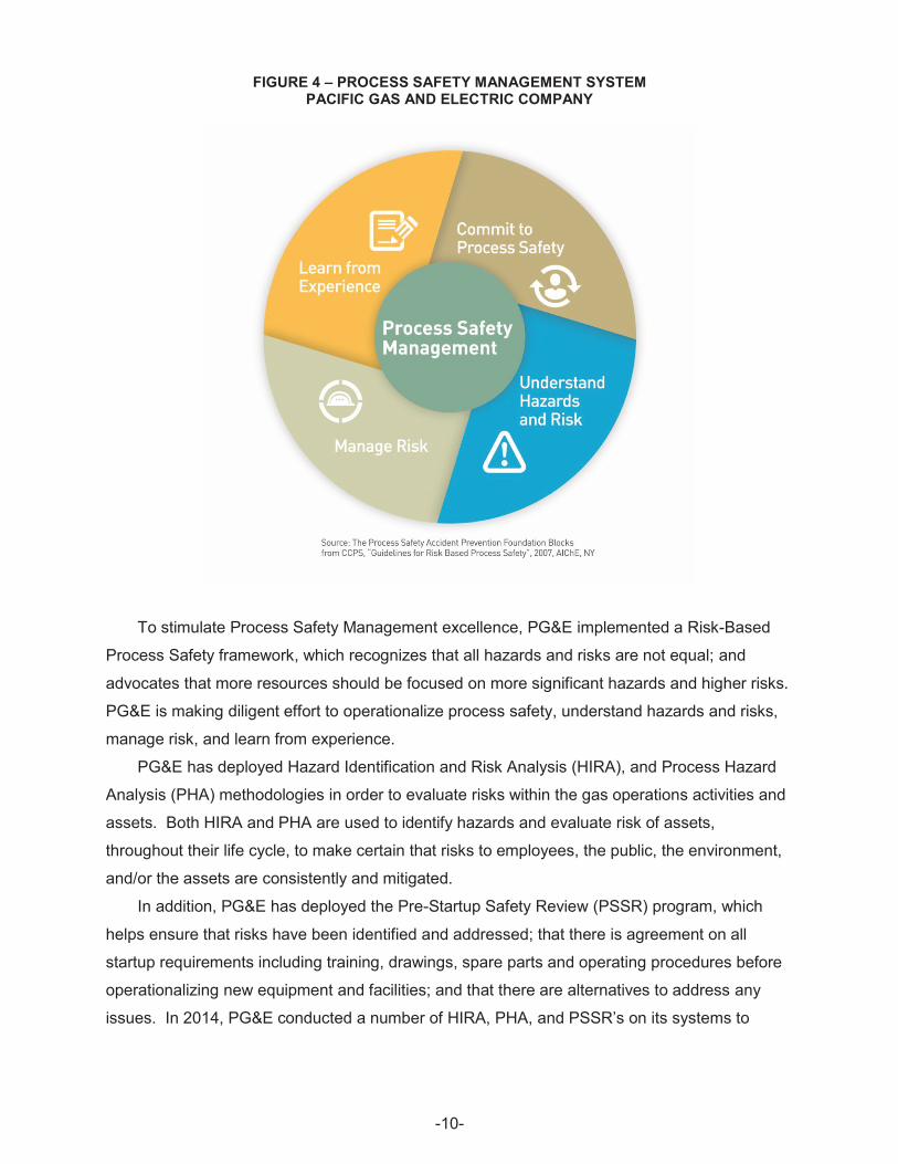
FIGURE 4 – PROCESS SAFETY MANAGEMENT SYSTEM PACIFIC GAS AND ELECTRIC COMPANY
To stimulate Process Safety Management excellence, PG&E implemented a Risk-Based
Process Safety framework, which recognizes that all hazards and risks are not equal; and
advocates that more resources should be focused on more significant hazards and higher risks.
PG&E is making diligent effort to operationalize process safety, understand hazards and risks,
manage risk, and learn from experience.
PG&E has deployed Hazard Identification and Risk Analysis (HIRA), and Process Hazard
Analysis (PHA) methodologies in order to evaluate risks within the gas operations activities and
assets. Both HIRA and PHA are used to identify hazards and evaluate risk of assets,
throughout their life cycle, to make certain that risks to employees, the public, the environment,
and/or the assets are consistently and mitigated.
In addition, PG&E has deployed the Pre-Startup Safety Review (PSSR) program, which
helps ensure that risks have been identified and addressed; that there is agreement on all
startup requirements including training, drawings, spare parts and operating procedures before
operationalizing new equipment and facilities; and that there are alternatives to address any
issues. In 2014, PG&E conducted a number of HIRA, PHA, and PSSR’s on its systems to
-10
augment our understanding of hazards and risks to enable effective planning and
implementation of layers of mitigating strategies.16
II. Achieving Safety through Asset Management A. Publicly Available Specification (PAS) 55 and International Organization for
Standardization (ISO 55001) PG&E Gas Operations has achieved the best practice asset management certifications
offered by the British Standards Institute under its PAS 55-1 and the recently released
ISO 55001 standards through the ISO, a world class standard for asset management. Both
provide an objective certification and an independent assessment of the completeness of the
asset management process. Attaining these certifications is a major milestone of achieving Gas
Safety Excellence. PG&E will need to continuously improve in order to maintain the
certifications on an ongoing basis
PAS 55-1 was first established in 2004, by a cross-section of utility and asset management
experts in response to demand from regulators and the industry for an asset management
standard that required objective assessment. PAS 55-1 was adopted in the United Kingdom
(UK) by the UK’s Office of Gas and Electric Markets to ensure that public utility and
infrastructure assets were being managed safely in a risk-informed manner. It is currently used
by over 50 public and private organizations in ten countries and fifteen industry sectors.
ISO 55001 was created by the international community as a response to the significant global
interest in asset management. ISO 55001 is based in large part on the PAS 55-1 standard.
Both PAS 55-1 and ISO 55001 standards specifically require evidence of alignment
between risk-informed plans and execution of those plans. They ensure that the principles of
safety, life cycle planning, risk management, cost/benefit, asset knowledge, customer focus and
sustainability are actually delivered within the day-to-day activities of designing, operating,
maintaining, and the eventual retirement/renewal of those assets and that the organization is
continuously learning and improving.
To meet these standards, PG&E developed a strategic plan for the organization and then
systematically, and in a coordinated fashion, implemented the plan to sustainably manage risks,
assets and asset systems, asset performance, and expenditures over their defined life cycles.
The standards assure alignment between PG&E’s integrated planning activities, the gas asset
management policy, standards, objectives, asset management plans, the risk register, and
specific work plans.
16 There are twenty elements to Process Safety Management which is discussed in Section III.
-11

PAS 55-1 and ISO 55001 standards require the creation and rollout of a strong line of sight
between the highest level organizational objectives to the activities of employees in the field.
They require that PG&E’s management team reviews, at least annually, the results of
communications, participation and consultation with employees and other stakeholders. The
third-party certification auditors will audit PG&E and its employees’ understanding of safe
operations, maintenance and improvement processes, and verify that there is a process in place
to continuously identify, address and improve issues.
PAS 55-1 and ISO 55001 standards encourage organizations to nurture a culture of
continuous improvement; in order to maintain accreditation it is imperative that the company is
able to demonstrate improvements in all aspects of the Asset Management System. To
maintain certification, PG&E will undergo annual independent audits of its asset management
processes, as well as an independent recertification audit every three years. PG&E is
committed to maintaining these certifications and meeting the high international standards that
the PAS 55-1 and ISO 55001 standards require, and their underlying principles of sustainable
safe operating processes and continuous improvement.
B. Risk Management Process 1. Enterprise and Operational Risk Management
PG&E is using a comprehensive enterprise and operational asset and risk management
process. PG&E’s Enterprise and Operational Risk Management (EORM) plans allow PG&E to
manage assets and risks at both an enterprise and operational level. The enterprise risks are
those that could threaten the viability of the company and may span multiple lines of business
(LOB). Operational risks arise from assets, people, processes and technologies within specific
LOBs within the company, such as the Gas Operations LOB. By assessing and managing risks
from both points of view, we can better manage the interdependencies and drive for consistency
among LOBs. In addition, this process increases senior management and board engagement in
risk-based decision-making by involving them in decisions as the process unfolds, and gives
those individuals charged with managing specific assets line of sight to other risks in the
enterprise.
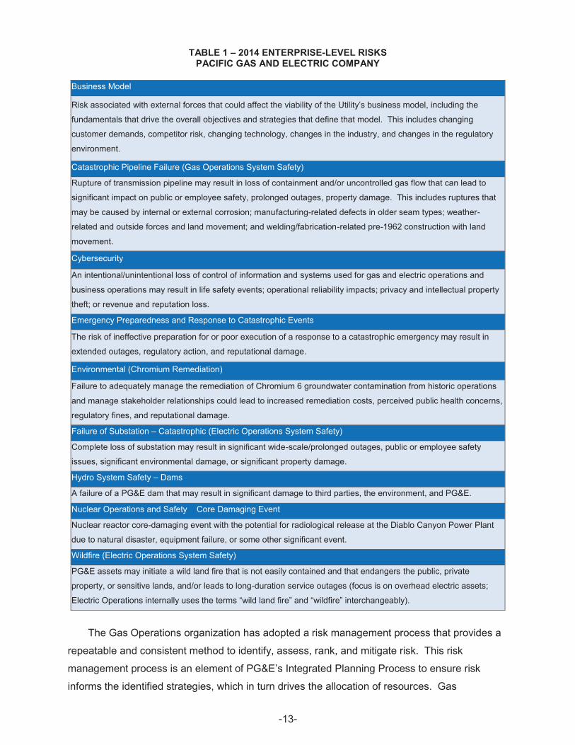
Potential key risks are identified by the LOBs and reviewed by the senior officers to develop
the 2014 enterprise-level risks that are shown in alphabetical order in Table 1.
-12
–
TABLE 1 – 2014 ENTERPRISE-LEVEL RISKS PACIFIC GAS AND ELECTRIC COMPANY
Business Model
Risk associated with external forces that could affect the viability of the Utility’s business model, including the
fundamentals that drive the overall objectives and strategies that define that model. This includes changing
customer demands, competitor risk, changing technology, changes in the industry, and changes in the regulatory
environment.
Catastrophic Pipeline Failure (Gas Operations System Safety)
Rupture of transmission pipeline may result in loss of containment and/or uncontrolled gas flow that can lead to
significant impact on public or employee safety, prolonged outages, property damage. This includes ruptures that
may be caused by internal or external corrosion; manufacturing-related defects in older seam types; weather-
related and outside forces and land movement; and welding/fabrication-related pre-1962 construction with land
movement.
Cybersecurity
An intentional/unintentional loss of control of information and systems used for gas and electric operations and
business operations may result in life safety events; operational reliability impacts; privacy and intellectual property
theft; or revenue and reputation loss.
Emergency Preparedness and Response to Catastrophic Events
The risk of ineffective preparation for or poor execution of a response to a catastrophic emergency may result in
extended outages, regulatory action, and reputational damage.
Environmental (Chromium Remediation)
Failure to adequately manage the remediation of Chromium 6 groundwater contamination from historic operations
and manage stakeholder relationships could lead to increased remediation costs, perceived public health concerns,
regulatory fines, and reputational damage.
Failure of Substation – Catastrophic (Electric Operations System Safety)
Complete loss of substation may result in significant wide-scale/prolonged outages, public or employee safety
issues, significant environmental damage, or significant property damage.
Hydro System Safety – Dams
A failure of a PG&E dam that may result in significant damage to third parties, the environment, and PG&E.
Nuclear Operations and Safety Core Damaging Event
Nuclear reactor core-damaging event with the potential for radiological release at the Diablo Canyon Power Plant
due to natural disaster, equipment failure, or some other significant event.
Wildfire (Electric Operations System Safety)
PG&E assets may initiate a wild land fire that is not easily contained and that endangers the public, private
property, or sensitive lands, and/or leads to long-duration service outages (focus is on overhead electric assets;
Electric Operations internally uses the terms “wild land fire” and “wildfire” interchangeably).
The Gas Operations organization has adopted a risk management process that provides a
repeatable and consistent method to identify, assess, rank, and mitigate risk. This risk
management process is an element of PG&E’s Integrated Planning Process to ensure risk
informs the identified strategies, which in turn drives the allocation of resources. Gas
-13
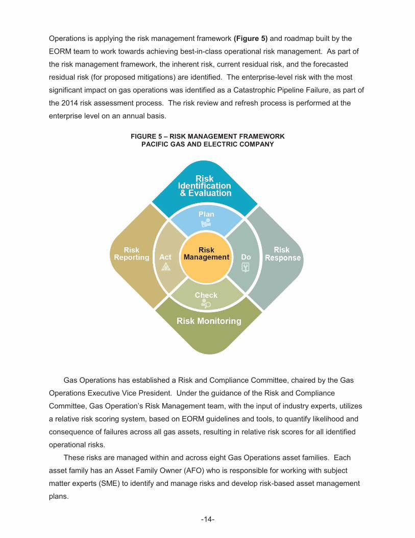
Operations is applying the risk management framework (Figure 5) and roadmap built by the
EORM team to work towards achieving best-in-class operational risk management. As part of
the risk management framework, the inherent risk, current residual risk, and the forecasted
residual risk (for proposed mitigations) are identified. The enterprise-level risk with the most
significant impact on gas operations was identified as a Catastrophic Pipeline Failure, as part of
the 2014 risk assessment process. The risk review and refresh process is performed at the
enterprise level on an annual basis.
FIGURE 5 – RISK MANAGEMENT FRAMEWORK PACIFIC GAS AND ELECTRIC COMPANY
Gas Operations has established a Risk and Compliance Committee, chaired by the Gas
Operations Executive Vice President. Under the guidance of the Risk and Compliance
Committee, Gas Operation’s Risk Management team, with the input of industry experts, utilizes
a relative risk scoring system, based on EORM guidelines and tools, to quantify likelihood and
consequence of failures across all gas assets, resulting in relative risk scores for all identified
operational risks.
These risks are managed within and across eight Gas Operations asset families. Each
asset family has an Asset Family Owner (AFO) who is responsible for working with subject
matter experts (SME) to identify and manage risks and develop risk-based asset management
plans.
-14
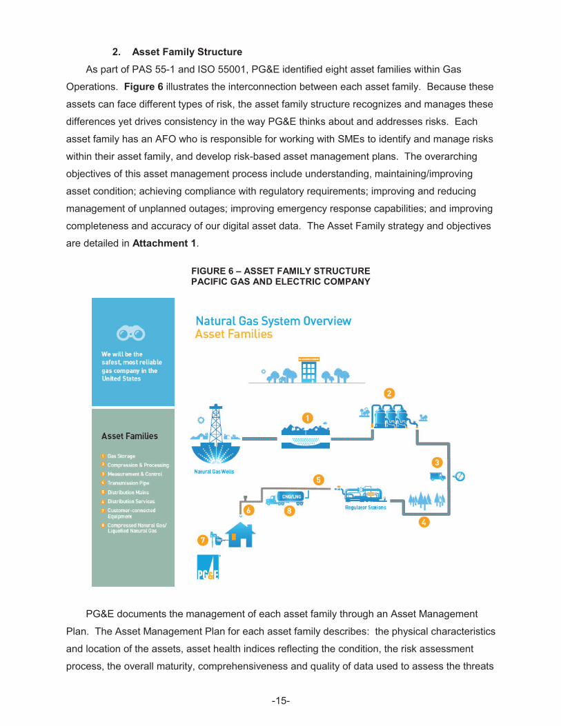
2. Asset Family Structure As part of PAS 55-1 and ISO 55001, PG&E identified eight asset families within Gas
Operations. Figure 6 illustrates the interconnection between each asset family. Because these
assets can face different types of risk, the asset family structure recognizes and manages these
differences yet drives consistency in the way PG&E thinks about and addresses risks. Each
asset family has an AFO who is responsible for working with SMEs to identify and manage risks
within their asset family, and develop risk-based asset management plans. The overarching
objectives of this asset management process include understanding, maintaining/improving
asset condition; achieving compliance with regulatory requirements; improving and reducing
management of unplanned outages; improving emergency response capabilities; and improving
completeness and accuracy of our digital asset data. The Asset Family strategy and objectives
are detailed in Attachment 1.
FIGURE 6 – ASSET FAMILY STRUCTURE PACIFIC GAS AND ELECTRIC COMPANY
PG&E documents the management of each asset family through an Asset Management
Plan. The Asset Management Plan for each asset family describes: the physical characteristics
and location of the assets, asset health indices reflecting the condition, the risk assessment
process, the overall maturity, comprehensiveness and quality of data used to assess the threats
-15
and risks, and a vision for the desired state of the assets. The plan identifies the potential
threats particular to that family of assets as well as the mitigation programs to reduce the risks
posed by such threats. The Asset Management Plans also include Key Performance Indicators,
which are metrics intended to measure progress and improvement in asset performance and
the effectiveness of mitigation programs. These Asset Management Plans are living
documents, evolving as new data becomes available.
The next sections describe the eight asset families and how their work aligns with safety.
This Asset Family structure is also described in detail in 2015 GT&S Rate Case.17
a. Transmission Pipe The Transmission Pipe asset family consists of line pipe used in transporting natural gas as
well as related major components, such as valves. PG&E’s Transmission Pipe asset family
includes pipe that transports gas from receipt points into PG&E’s natural gas transmission
system until the gas is delivered into PG&E’s natural gas distribution system and falls under
PG&E’s Transmission Integrity Management Program (TIMP). TIMP governs how PG&E
assesses performance and identifies risks that need mitigation. It is a core foundation of
PG&E’s ongoing efforts to provide safe and reliable service, consistent with industry best
practices, and is based on the federal TIMP regulation as set forth in 49 Code of Federal
Regulations (CFR) 192, Subpart O.
Historically, PG&E identified 5,808 miles18 of its line pipe to be transmission. As we
prepared for PAS 55 certification by separating assets into asset families, PG&E reviewed the
categorization of our transmission and distribution assets. In addition, PG&E reviewed this
categorization in light of 49 CFR 192.3 and recent PHMSA (U.S. Department of Transportation
(DOT)) interpretation letters. As a result, PG&E defined an additional approximately 920 miles
of line pipe to be transmission rather than distribution. This brings the total of transmission pipe
to approximately 6,750 miles.
The federal code treats pipe and related assets as belonging to transmission—rather than
distribution—if it meets any one of three prongs. These are:
i. A change of function from transporting gas to delivery to a distribution center or to a
large customer not downstream of a distribution center;
17 2015 GT&S Rate Case Application (A.) 13-12-012. 18 Based on the 2012 PHMSA 7100 report.
-16
ii. Operating at a hoop stress of 20 percent or more of Specified Minimum Yield
Strength (SMYS);19 or
iii. Transporting gas to or within a natural gas storage field.
For PG&E, the main change in this reclassification revolves around the physical location of
the “distribution center” where the function changes from transporting gas to distributing it for
two or more customers. It involves line pipe segments and related components. The change
means these segments will be included on a more frequent maintenance and inspection
schedule and, depending on the density and types of buildings in close proximity to these
segments, may qualify for inclusion in the Transmission Integrity Management Program. It also
ensures that pipeline segments are treated as belonging to transmission or distribution for all
purposes, not just for integrity management purposes.
The Transmission Pipe Asset Management Plan describes the roadmap for mitigating and
managing risk for this asset family and achieving the established asset management objectives.
Some of the plans objectives include the following:
x Expand rigorous integrity management principles beyond High Consequence Areas
(HCA);
x Shift primary method of assessing HCAs from External Corrosion Direct
Assessment to ILI based integrity assessments;
x Shorten pipeline isolation and response times in populated areas;
x Eliminate over-pressure events;
x Enhance public awareness and emergency response capabilities;
x Implement pipeline pathways to achieve a delineated right-of-way, and continue to
evaluate, refine and improve threat assessment and mitigation procedures;
x Maintain and further develop our core monitoring and preventative maintenance
programs; and
x Maintain our knowledge on our assets, allowing for informed, risk based decision
making.
The transmission asset management plan describes these objectives in detail and is
included as Attachment 2. A more in-depth discussion of specific programs, such as ILI, Direct
assessment, and the addition of the approximate 920 transmission miles, prioritized for 2015
are also discussed in Chapter 4 of PG&E’s 2015 GT&S rate case.
19 SMYS means the Specified Minimum Yield Strength for steel pipe manufactured in accordance with a listed specification. This is a common term used in the oil and gas industry for steel pipe used under the jurisdiction of the DOT. It is an indication of the minimum stress a pipe may experience that will cause plastic (permanent) deformation.
-17
b. Distribution Mains and Services The Gas Distribution Asset Families include the Distribution Main Asset Family and the
Distribution Service Asset Family, which fall under PG&E’s Distribution Integrity Management
Program (DIMP). Regulations govern how PG&E inspects and maintains more than
42,000 miles of pipe, 3.3 million gas service connections, and other gas distribution assets. The
DIMP governs how PG&E assesses performance and identifies risks that need mitigation. It is
a core foundation of PG&E’s ongoing efforts to provide safe and reliable service, consistent with
industry best practices, and is based on the federal DIMP regulation as set forth in Title 49 of
the Code of Federal Regulations – Transportation (49 CFR) 192.1007.20 The DIMP applies to
all gas distribution assets and facilities.
The Gas Distribution Mains and Services Asset Management Plan summarizes risks to
PG&E’s gas distribution system and proposes mitigations to address those risks. The
distribution asset management plan describes the roadmap for achieving the asset
management objectives. Some of the plans objectives include the following:
x Improving leak performance;
x Reducing and managing the leak backlog;
x Evaluating cathodic protection on metallic distribution mains;
x Reducing size of emergency shutdown zones;
x Reducing third-party dig-ins;
x Reducing major over-pressure events
x Ensuring DIMP regulatory compliance;
x Effectively scheduling planned outages in advance; and
x Improving completeness and accuracy of digital data.
The distribution asset management plan describes these objectives in detail and is included
as Attachment 3.
c. Gas Storage The Gas Storage Asset Family includes PG&E’s owned and operated underground gas
storage fields. The objective of the plan is to identify the threats, risks, and condition of the
asset, and identify programs to reduce the risk for all components contained within the
boundaries of the Gas Storage asset family.
The Gas Storage Asset Management Plan describes the roadmap for achieving the asset
management objectives. Some of the plans objectives include the following:
Assess and monitor field and storage wells;
20 CFR 192, Subpart P, published on December 4, 2009 at 74 CFR 63929.
-18
x
x Approval of the well integrity management program and risk assessment process
by the Department of Oil, Gas and Geothermal Resources;
x Evaluate field and well performance in real time;
x Understand health of control system on overflow controls and monitoring;
x Utilize electronic data to understand well condition on real time basis; and
x Capture existing well files on well integrity in electronic database.
The gas storage management plan describes these objectives in detail and is included as
Attachment 4.
d. Compression & Processing The Compression and Processing Asset Family includes the compressor units and
associated equipment installed at nine compressor stations; and, compressor units and gas
processing facilities installed at three underground storage facilities. Additionally, this asset
family includes gas processing and conditioning equipment installed at four transmission
dehydration stations, as well as, gas odorizers and associated equipment installed systemwide.
The Compression and Processing Asset Management Plan describes the roadmap for
achieving the asset management objectives. Some of the plans main objectives include the
following:
x Improve performance for completing and closing corrective work;
x Ensure that critical documents required for compression and processing are
completed;
x Implement site-specific corrosion monitoring programs to enhance existing
programs;
x Investigate and incorporate process safety concepts;
x Implement program to improve visibility of condition and criticality of assets to
reduce the number of unscheduled shutdowns of compressor units;
x Develop and implement equipment obsolescence program;
x Develop best in class guidance document and Maintenance & Operations training
on work procedures and specialized gas processing equipment; and
x Develop robust metrics and targets, and issue the Gas Transmission Engineering &
Design Manual to provide uniformity of installed systems.
The compression asset management plan describes all objectives in detail and is included
as Attachment 5. As part of continuous improvement and safety, PG&E has requested funding
for multiple projects such as Engineering Critical Assessment, rebuilding aging infrastructure,
-19
replacements of certain compressor units, mitigating threats by enhancing record keeping and
physical security, among other programs, in Chapter 6 of its 2015 GT&S rate case.
e. Measurement & Control The Measurement and Control Asset Family includes transmission and distribution stations
that control pressure and gas measurement equipment, and are critical to providing safe and
reliable delivery of natural gas.
The Measurement and Control Asset Management Plan describes the roadmap for
achieving the asset management objectives. The objectives of this plan are similar to the
compression and processing objectives that are included above in Section d. The
Measurement and Control asset management plan describes its objectives in detail and is
included as Attachment 6. Similar to Compression and Processing above, PG&E has
requested funding for multiple projects in Chapter 6 of its 2015 GT&S rate case related to
transmission related Measurement and Control equipment.
f. Customer Connection Equipment The Customer Connection Equipment Asset Family is comprised of over 4.4 million billing
meters and associated regulators, over-protection devices, shut-off valves, piping, and fittings
that connect the gas distribution service to the customer. Customer meters are used to
measure gas usage to support the billing function.
The Customer Connection Equipment Asset Management Plan describes the roadmap for
achieving the asset management objectives. Some of the plans objectives include the
following:
x Reduce and manage leak backlog;
x Identify and remove problematic customer regulators;
x Reduce unplanned meter change-outs;
x Complete meter protection program;
x Execute meter change plan in accordance with regulatory requirements;
x Maintain meter accuracy within industry accepted standards; and
x Maintain complete and quality data.
The customer connected asset management plan describes its objectives in detail and is
included as Attachment 7.
g. Compressed Natural Gas/Liquefied Natural Gas The Compressed Natural Gas (CNG) and Liquefied Natural Gas (LNG) Asset Families
consist of (1) portable equipment that can store and transport gas on public highways, and
-20
deliver this gas to PG&E or PG&E customer pipeline systems to supplement or substitute for
normal pipeline flowing supplies; and (2) LNG and CNG vehicle fueling stations that are part of
the natural gas delivery system.
The portable equipment falls into two basic categories:
x Portable gas supplies in the form of LNG and CNG in highway truck trailers.
x Portable injection equipment which allows the delivery of gas from portable
supplies equipment to PG&E customers or pipeline systems.
The LNG/CNG Asset Management Plan describes the roadmap for achieving the asset
management objectives. Some of the plans objectives include the following:
x Minimize threats that lead to the risk of loss of containment, and to reduce health
and safety risks;
x Minimize threat of equipment failure; and
x Reduce risk of unavailability of the portable system service delivery.
The CNG/LNG plan describes its objectives in detail and is included as Attachment 8.
The LNG and CNG Fueling Station Asset Management Plan describes the roadmap for
achieving the asset management objectives. Natural gas is applied to the stations by PG&E's
distribution pipeline network, and the stations supply gas as fuel to PG&E and third-party
vehicles. This asset management plan is included as Attachment 9.
3. Understanding Risks to the Asset Families a. Risk Framework
There are three principal, overarching risks for Gas Operations: (1) loss of containment;
(2) loss of supply and service; and (3) inadequate response and recovery:
1) Loss of containment: Risk that gas will escape the system in an uncontrolled
manner. PG&E’s plan to mitigate this risk is driven by its operational risk assessment
and integrity management programs including Distribution Integrity Management,
Transmission Integrity Management, and Damage Prevention, among others. These
programs focus on identifying ways to mitigate the risks associated with identified
“threats,” including corrosion, natural forces, excavation damage, other outside force
damage, material, weld or joint failure, equipment failure, and incorrect operation.
2) Loss of supply and service: Risk that PG&E will be unable to deliver natural gas to
one or more customers. PG&E’s plan to mitigate this risk is largely driven by
Systems Operations and by the new Gas Control Center. Systems Operations is
-21
focusing on three risk mitigation drivers: (1) process; (2) visibility; and (3) control.
PG&E will be instituting new processes and installing a significant number of
additional monitoring and control points to mitigate these risks. In addition to
Systems Operations, PG&E’s efforts to mitigate this risk include investing in capacity,
including new business, investing in training so that people execute work properly
and investing in technology.
3) Inadequate response and recover: Risk that, if there is an unplanned loss of
containment or loss of supply or service, PG&E will not be able to adequately
respond to make the situation safe. Mitigating this risk involves proper training, a
robust emergency response plan including an established and structural Incident
Command System (ICS), and coordination both internally as well as with external first
response agencies.
As part of PG&E’s evaluation of pipeline safety relative to Loss of Containment, potential
threats are considered as outlined in the American Society of Mechanical Engineers (ASME),
publication B31.8S. This standard is specifically designed to provide the operator with the
information necessary to develop and implement an effective integrity management program
utilizing proven industry practices and processes. Gas Operations applies the processes and
approaches within this Standard to each of the eight asset families.
The threats considered include those listed in ASME B31.8S, as identified below:
1) Time dependent threats (which are threats that potentially increase over time, such
as corrosion).
2) Stable or “resident” threats (which are threats that are present, or inherent to the
asset, such as manufacturing or construction defects, but do not pose a threat unless
acted upon by outside forces).
3) Time independent threats (which are threats such as third party excavation damage,
incorrect operations, or weather related and outside forces such as land movement or
terrorism).
The results of the threat assessments described in Table 2 below are used to identify and
prioritize the mitigation programs for the gas system.
-22
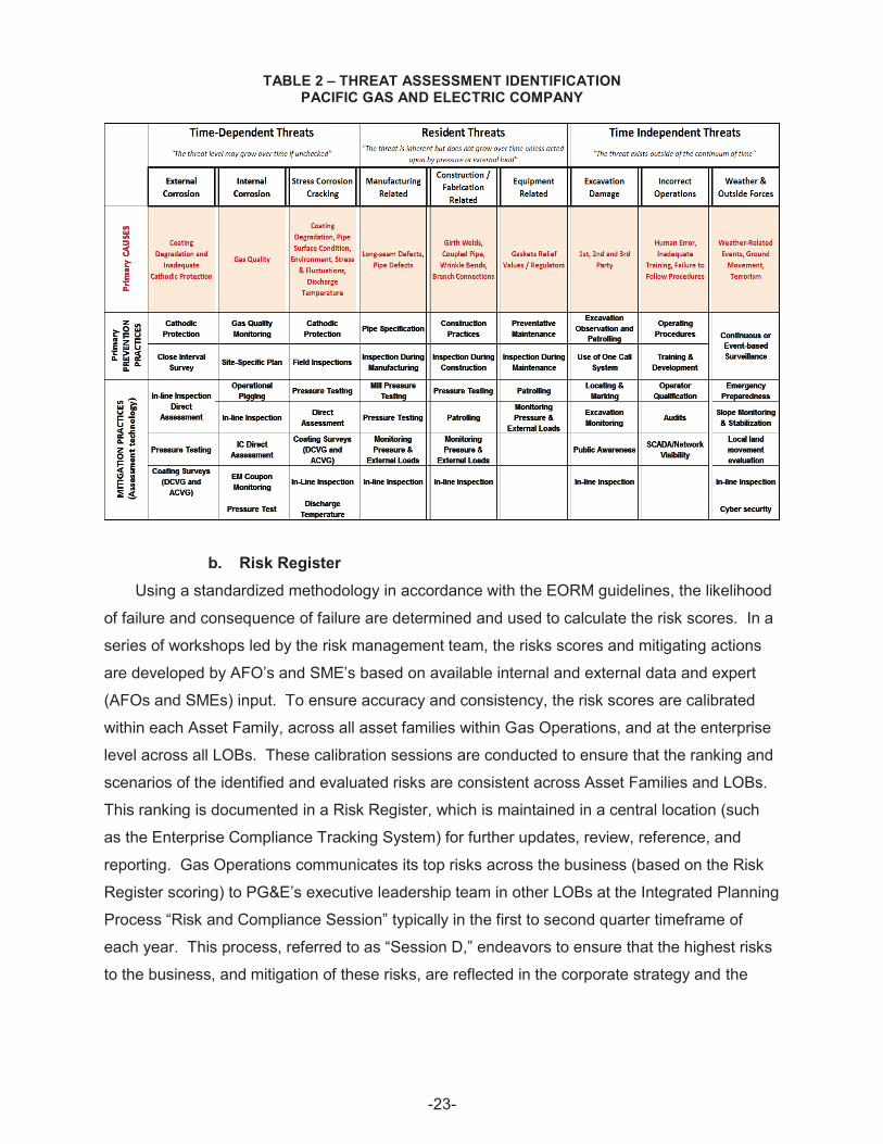
TABLE 2 – THREAT ASSESSMENT IDENTIFICATION PACIFIC GAS AND ELECTRIC COMPANY
b. Risk Register Using a standardized methodology in accordance with the EORM guidelines, the likelihood
of failure and consequence of failure are determined and used to calculate the risk scores. In a
series of workshops led by the risk management team, the risks scores and mitigating actions
are developed by AFO’s and SME’s based on available internal and external data and expert
(AFOs and SMEs) input. To ensure accuracy and consistency, the risk scores are calibrated
within each Asset Family, across all asset families within Gas Operations, and at the enterprise
level across all LOBs. These calibration sessions are conducted to ensure that the ranking and
scenarios of the identified and evaluated risks are consistent across Asset Families and LOBs.
This ranking is documented in a Risk Register, which is maintained in a central location (such
as the Enterprise Compliance Tracking System) for further updates, review, reference, and
reporting. Gas Operations communicates its top risks across the business (based on the Risk
Register scoring) to PG&E’s executive leadership team in other LOBs at the Integrated Planning
Process “Risk and Compliance Session” typically in the first to second quarter timeframe of
each year. This process, referred to as “Session D,” endeavors to ensure that the highest risks
to the business, and mitigation of these risks, are reflected in the corporate strategy and the
-23
–
executable investment plans as part of Session 1 and Session 2.21 Risks, including the key
risks for each asset family identified during Session D, are captured within the asset
management plans, mitigation programs, and work projects.
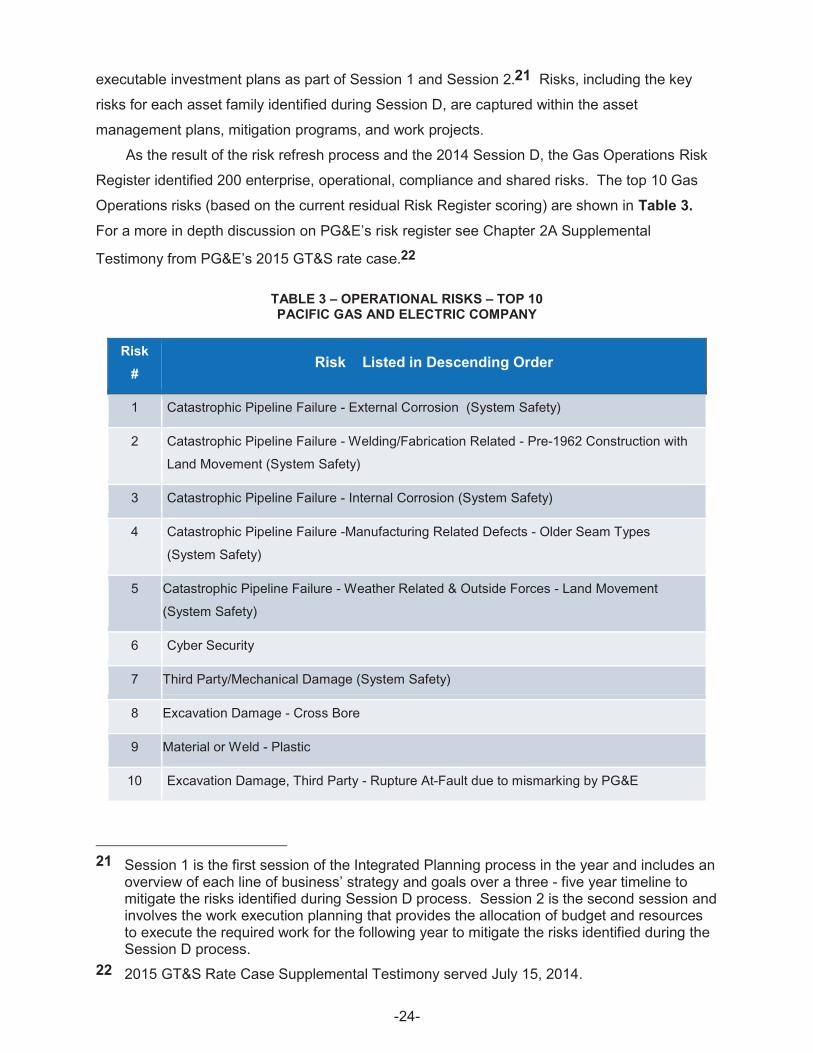
As the result of the risk refresh process and the 2014 Session D, the Gas Operations Risk
Register identified 200 enterprise, operational, compliance and shared risks. The top 10 Gas
Operations risks (based on the current residual Risk Register scoring) are shown in Table 3. For a more in depth discussion on PG&E’s risk register see Chapter 2A Supplemental
Testimony from PG&E’s 2015 GT&S rate case.22
TABLE 3 – OPERATIONAL RISKS – TOP 10 PACIFIC GAS AND ELECTRIC COMPANY
Risk #
Risk Listed in Descending Order
1 Catastrophic Pipeline Failure - External Corrosion (System Safety)
2 Catastrophic Pipeline Failure - Welding/Fabrication Related - Pre-1962 Construction with
Land Movement (System Safety)
3 Catastrophic Pipeline Failure - Internal Corrosion (System Safety)
4 Catastrophic Pipeline Failure -Manufacturing Related Defects - Older Seam Types
(System Safety)
5 Catastrophic Pipeline Failure - Weather Related & Outside Forces - Land Movement
(System Safety)
6 Cyber Security
7 Third Party/Mechanical Damage (System Safety)
8 Excavation Damage - Cross Bore
9 Material or Weld - Plastic
10 Excavation Damage, Third Party - Rupture At-Fault due to mismarking by PG&E
21 Session 1 is the first session of the Integrated Planning process in the year and includes an overview of each line of business’ strategy and goals over a three - five year timeline to mitigate the risks identified during Session D process. Session 2 is the second session and involves the work execution planning that provides the allocation of budget and resources to execute the required work for the following year to mitigate the risks identified during the Session D process.
22 2015 GT&S Rate Case Supplemental Testimony served July 15, 2014.
-24
4. Mitigation Programs to Reduce Risk This section describes programs PG&E has in place to mitigate risks to its pipeline system.
a. Mitigating Loss of Containment a) Damage Prevention
Damage Prevention is an end-to-end process that includes the field location of underground
facilities as requested through the Underground Service Alert (USA) One-Call system, USA
ticket management, investigations associated with dig-ins, and damage claims. The marking of
underground utilities is governed by California Government Code 4216 and the process is
driven by industry best practices.23
Damage Prevention consists of multiple processes working together to help prevent
damages from all excavation activities, including legislative support. Activities include Public
Awareness, Dig-In Prevention, and Locate and Mark. PG&E’s Damage Prevention processes
are reviewed annually. Each process is described in detail in the next sections. Damage
prevention program also addresses and helps mitigate Risk #7 and #10 in Table 3 above.
I) Public Awareness Public Awareness is another key process to ensure safety, and consists of educating
customers and other key audiences regarding excavation rules, laws, and best practices.
Efforts in this area include, but are not limited to, sending bill inserts in the mail, making
education links available on email bill pay, sending individual separate mailers, running ads in
newspapers and on the radio, conducting companywide campaigns for Call 811 Before You Dig,
and attending USA S.A.F.E. events that involve educating excavator companies of safe digging
practices and recommendations. PG&E’s Public Awareness Plan (PAP), documented in
PG&E’s Risk Management Plan 12 (RMP-12) (Attachment 10), includes performance metrics
and guidelines for evaluating the plan and for continuous program improvement.
The primary objectives of the PAP include awareness, damage prevention, and emergency
response readiness. On an annual basis the Public Awareness Administrator or designated
resource, conducts a review and develops a written report that summarizes program
implementation details and outreach efforts and provides an assessment of message
comprehension and understanding and a summary of stakeholder feedback collected during the
year. The report also provides details regarding any notable fluctuations compared to previous
years. Stakeholder feedback may include:
Survey data collected at meetings from emergency responders and excavators;
23 Pursuant to 49 CFR §192.614, PG&E is required to have a Damage Prevention Program.
-25
x
x Stakeholder feedback collected through phone surveys, mail surveys, online
surveys, focus groups or stakeholder interviews; and
x Pre-Testing—reports from focus groups, employee interviews or online panels;
conducted to gauge message clarity and understandability of program materials.
The results document the number of third-party incidents during the previous year, near
hits, and any additional data tracked by Damage Prevention that is helpful in understanding
excavator needs, issues and trends. Planned program changes for the upcoming years are
based on recommendations provided by the Public Awareness Program Committee, employees
or vendors that support the program will also be included.
II) Dig-In Prevention Dig-In prevention consists of determining the root causes of excavation damage to PG&E's
facilities, identifying process improvements to reduce damages, and actively pursuing cost
recovery for damage from responsible excavators through PG&E’s claims department, and
other enforcement processes. Process improvements currently in progress include:
x Integration of “caution tape” into PG&E’s construction standards, which provides
excavators with a tell-tale sign that gas facilities are below;
x Training of internal excavators to conduct a “pre-sweep” prior to excavation,
ensuring that all structures are identified;
x Deployment of PG&E’s “Damage Prevention Manual” to provide clearer instruction
around critical steps, including troubleshooting of “difficult to locate” facilities;
x Deploying two senior-level investigators to oversee and enhance PG&E’s ability to
investigate dig-ins;
x Developing a “Gold Shovel Standards” program to reward contractors who practice
safe excavation, and deploying a “Habitual Offender” program to properly address
contractors who don’t;
x Developing an “811 Ambassador” program to train the PG&E employee to be able
to properly identify unsafe excavation activities and take appropriate intervention
measures;
x Developing the “Home Owner Association (HOA)” program in hopes to persuade
HOAs to adopt requirements that residents call 811 before excavating;
x Utilizing aerial patrolling to identify and intercept threats to the transmission
system; and
x Completing the Lean Six-Sigma analysis of PG&E’s claims process to ensure
recapture of costs associated with third-party dig-ins is one timely and in an
effective manner.
-26
III) Locate and Mark Locate and mark program addresses and help mitigate Risk #10 in Table 3 above. Federal
pipeline safety regulations24 and California state law25 require that PG&E belongs to, and
shares the costs of, operating the regional “one call” notification system. Builders, contractors,
and others planning to excavate, must use this system to notify underground facility owners, like
PG&E, of their plans to excavate. PG&E then provides the excavators with information about
the location of its underground facilities. Information is normally provided by having company
personnel visit the work site and place color coded surface markings to show where any pipes
and wires are located. Because of its large service territory, PG&E belongs to two regional one
call systems which share a common toll free, three digit “811” telephone number. The California
one call systems are commonly referred to as USA.
b) Distribution Pipeline Replacement An important element of providing safe gas distribution service is replacing aging assets.
PG&E uses age, materials, seismic factors, and gas leaks to identify and prioritize gas mains for
replacement. In addition to gas main replacement, the program covers related service
replacement and meter relocation work.
PG&E prioritizes gas distribution pipeline replacement projects based on a risk and
reliability determination, which includes the probability of a leak on each section of pipe and the
potential consequences of that leak. Each section of pipe is assigned a priority value
corresponding with this probability and consequence of a leak. The company maintains a
database of gas pipeline replacement pipe and updates the priority values in the Gas Pipeline
Replacement Program.
In addition to the Gas Pipeline Replacement Program, which is focused on replacing pre
1940 steel pipe, PG&E has initiated two other replacement programs to improve distribution
safety: Copper services replacement, and Aldyl-A distribution pipe replacement. Between
2007, and the end of 2013, PG&E replaced approximately 39,500 copper services through the
Copper Services Replacement Program. A number of copper services remain that are being
coordinated with street paving moratoriums and pipeline replacement projects.
Certain vintages of Aldyl-A plastic have shown a susceptibility to cracking creating the
potential for gas leaks. As a result, PG&E inventoried the gas distribution system to identify the
location and vintages of Aldyl-A plastic pipe and initiated a replacement program in 2012.
Approximately 25 miles were replaced in 2012, approximately 40 miles were replaced in 2013,
24 49 CFR §192.614. 25 Code §4216.
-27
with 35 miles planned for replacement in 2014. In total, PG&E is planning to replace
approximately 1,500 miles of the approximately 5,535 miles of Aldyl-A pipe over the next 15 to
20 years.
c) Cross-Bore Mitigation A cross-bore is a gas main or service that has been installed using trenchless technology
resulting in the gas pipe being installed unintentionally through a waste-water, or storm-drain
system. Cross-bores pose a gas system risk in that they can result in a gas leak into the sewer
system during mechanical sewer cleaning operations. PG&E has an inspection program to
identify and remediate legacy cross bores. PG&E has overseen the development and
implementation of the Cross-bore Safety Inspection Program to minimize the potential risks of
legacy Cross Bores. The goal of the Program is to identify cross-bores by completing
inspections of potential conflict locations and repairing all occurrences discovered throughout
the entire PG&E service territory. This program addresses and helps mitigated Risk #8 in
Table 3 above.
The Program takes input from PG&E records indicating where trenchless construction
methods were used to install or replace gas services and mains. A Geographic Information
System (GIS) is utilized to plan and assign work areas for the closed circuit television video
inspection of the interior of sewer pipes to identify where they may be compromised by gas
pipes. GIS also enables the tracking of inspection and repair status. Each cross-bore that is
identified is tracked from identification to completion. DIMP tracks each cross bore and key
information such as location, discovery date, main or service, year of installation, program
installation, repair status, and repair date. DIMP also conducts public outreach on cross-bore
safety by sending safety brochures on cross-bores to sewer districts, public works agencies,
licensed plumbers, plumbers union, and equipment rental stores. In March 2014, DIMP sent out
a bill insert to PG&E customers discussing cross-bore and safety message.
In addition, PG&E is implementing a cross-bore prevention program that will make use of
pre- and post-video camera inspections to verify no damage occurs to sewer lines when using
trenchless installation during construction.
a) Hydrostatic Strength Testing Hydrostatic strength testing mitigates threats by testing the yield strength of the pipe for the
presence of manufacturing defects, such as lack of fusion in a seam weld. PG&E’s hydrostatic
testing program validates the integrity and assures a margin of safety for its gas transmission
pipelines. As part of its Pipeline Safety Enhancement Plan (PSEP),26 PG&E has completed an
26 PG&E filed its PSEP on August 26, 2011, for activities (such as strength testing, pipeline replacement, ILI, and automated valves) from 2011 through the end of 2014.
-28
unprecedented amount of work. As of July 31, 2014, PG&E has validated strength testing
(either through records verification or hydrostatic testing) a total of 753 miles of transmission
pipeline, which includes 595 miles validated through hydrostatic pressure testing; installed
161 automatic and remote control valves that will automatically shut off gas in an emergency;
validated MAOP for all 6,750 miles of its gas transmission pipelines; replaced approximately
89 miles of transmission pipeline; downrated 11.6 miles of transmission pipeline;27 retired
8.7 miles of transmission pipeline;28 and collected and digitized more than 3.7 million pipeline
records as we implement an advanced Records and Information Management (RIM) system
with next-generation technology and tools.
PG&E selected and prioritized the work using the PSEP decision trees,29 which focused on
enhancing the pipeline integrity in segments that had not previously been subjected to a
pressure test. The work was prioritized based on location of pipeline segments in HCA, and
Class 3 and 4 locations that were operating at a SMYS of 30 percent or greater. This served as
a good foundation to manage the potential risk by pipeline segments that had not previously
been subjected to pressure testing. PG&E is now moving towards a more holistic approach to
prioritizing the management of risk arising from the threats to its Transmission Pipe assets and
will be rolling future work into its prioritized work plan such as vintage pipe replacement, valve
automation, and ILI retrofitting,30 which will be discussed in the next sections of this Plan.
PG&E will strength test or replace its entire gas transmission pipeline that was not
previously tested, in roughly 12-15 years from the start of strength testing in 2011. PG&E is
prioritizing its work based on the following priorities listed in order of importance: (i) HCA
segments, (ii) Integrity Management Threats; (iii) Class 3 non-HCA segments; (iv) Class 1 and
Class 2 non-HCA segments; and (v) short segments.31 The hydrostatic testing strength
program addresses and helps mitigate Risk #2 in Table 3 above.
27 To downrate a transmission pipeline is to lower its operating pressure to that of distribution pressure (60 pounds per square inch gauge (psig) or less).
28 To retire a pipeline is to remove it from service and not replace it with any other pipe. 29 PSEP decision trees were approved by the Commission in D.12-12-030. 30 As demonstrated in the mitigation plans set forth in Chapters 4A and 4B of PG&E’s
2015 GT&S rate case. For further discussion of PG&E’s plans for future work see the discussion in Chapter 4A of PG&E’s 2015 GT&S rate case.
31 See Chapter 4A of PG&E’s 2015 GT&S rate case for an in-depth discussion on the hydrostatic testing program.
-29
b) Vintage Pipeline Replacement A significant portion of PG&E’s natural gas pipeline system—approximately 47 percent—
was designed, manufactured, constructed, and installed before the start of California pipeline
safety laws in 1961. While age alone does not pose a threat to pipeline integrity, age does play
a role because of the type of vintage manufacturing and construction practices that were
acceptable at that time.32 PG&E considers “vintage pipe” to include pipe manufactured or
constructed and fabricated using certain historic practices that are no longer being used today.
Historic manufacturing methods include pipe made with flash welds, low frequency Electric
Resistance Welded seam, single submerged arc welded seams, or furnace lap welded seams.
Historic fabrication and construction methods include pipe that was installed using wrinkle
bends, mechanical/compression couplings, miter bends and other non-standard fittings like
orange peel reducers, chill ring welds, bell and spigot, or pipe that was constructed with the
acetylene girth welding process.
PG&E’s Vintage Pipeline Replacement program is primarily focused on removal of historic
fabrication and construction methods that are not as readily assessed using ILI or hydrostatic
testing. The vintage pipeline replacement program accounts for the fact that in some cases
vintage pipe with manufacturing threats are more appropriately managed through replacement,
rather than through the hydrostatic testing program. This program addresses and helps mitigate
Risk #4 and #9 in Table 3 above.
PG&E has identified approximately 630 miles of transmission pipe, with characteristics that
make it more susceptible to certain construction threats. Of those 630 miles, PG&E has further
identified approximately 370 miles of vintage pipe where fabrication and construction threats
interact with land movement.33
PG&E follows the ASME B31.8S threat matrix and in its Vintage Pipeline Replacement
program targets the threat posed by the presence of these construction defects as they interact
with outside forces such as land movement.34
32 This is supported by the report, “The Role of Age in Pipeline Safety,” prepared for the INGAA Foundation, Inc., by John F. Kiefner and Michael J. Rosenfeld, November 8, 2012, Report No 2012.04, which concluded that 85 percent of incidents occurred irrespective of a pipeline’s age, with 15 percent related in some way to the age of the pipeline.
33 Land movement is considered a Weather-Related Outside Force threat. Types of land movement addressed include slow land movement, liquefaction, areas of seismic activity, creep, and other types of land movement.
34 See Chapter 4A of PG&E’s 2015 GT&S rate case for an in-depth discussion on the Vintage Pipe Replacement.
-30
c) In-Line Inspection Retrofitting ILI is the most reliable pipeline integrity assessment tool currently available to natural gas
pipeline operators to assess the internal and external condition of transmission line pipe. ILI
enables a pipeline operator to learn about the condition of its pipelines and to predict the
integrity of those pipelines into the future to address time dependent as well as other threats to
pipeline integrity. It involves running technologically advanced inspection tools, often called
“smart pigs,” through the inside of the pipeline to collect data about the pipe, and then using that
data to identify anomalies that may require further investigation or repair. The ILI program
addresses and helps mitigate Risk #1 and #3 in Table 3 above.
PG&E plans to: (1) continue modifying or upgrading the existing pipeline system at an
accelerated rate to accommodate an ILI tool; (2) conducting cleaning and inspection “runs” in
the pipeline; and (3) conducting Direct Examination and Repair (DE&R) after data analysis is
complete. After modifying or upgrading the pipeline system to make the pipelines piggable,
inspection runs are generally divided into first-time inspection runs for initial and baseline
assessment, and re-inspection runs conducted for re-assessment purposes.
The DE&R remediation effort allows for the preventive repair and mitigation of anomalies
before they result in a pipeline leak or rupture. The federal safety regulations
(49 CFR §192.933) as well as the integrity management industry standard, “Managing System
Integrity of Gas Pipelines (2004)” ASME B31.8S prescribe the actions and schedule of the
excavation and repair (or replacement of the pipe) based on the data analysis. Anomalies are
characterized as: (1) immediate; (2) scheduled; and (3) monitored. Anomalies categorized as
immediate require a temporary pressure reduction and an expedited response.
After a dig is completed, PG&E identifies the cause of the anomalies. This information is
used to generate mitigation activities to improve the long-term safety and reliability of the
pipeline. A post-assessment of the line is performed to re-evaluate all of the threats identified
on the line, establish the next integrity re-assessment date and determine if any identified issues
apply to other facilities. A PG&E final report is created for each ILI job which marks the
completion of the DE&R.35
d) Corrosion Program Corrosion is a naturally occurring process that reduces the effectiveness of steel to contain
pressurized natural gas. It is a threat that adversely affects the longevity and reliability of
natural gas pipelines, valves, pressure vessels, and other pipeline appurtenances such as
compressors, metering, and regulator stations. PG&E has identified corrosion as one of the top
35 See Chapter 4A of PG&E’s 2015 GT&S rate case for an in-depth discussion on the ILI program.
-31
threats to PG&E’s natural GT&S assets. Starting in 2013, PG&E initiated significant
improvements to its Corrosion Control Program and is moving towards the industry best
practices of creating a corrosion control “discipline.” Elements of such a discipline include
concepts such as centralized management with a commitment to corrosion control, employing
qualified SMEs, and creating industry standards-based, common approaches to corrosion
control on topics such as collection, analysis and integration of accurate and reliable data on
which to make risk-based decisions about mitigation efforts.
To better mitigate the threat of external corrosion, PG&E plans to: (1) enhance its cathodic
protection system; (2) conduct system-wide close interval surveys; and (3) identify and
remediate locations with confirmed electrical interference from Alternating Current or Direct
Current. To better mitigate the threat of internal corrosion, PG&E plans to implement site
specific plans and enhance gas quality monitoring. To better mitigate the threat of atmospheric
corrosion, PG&E plans to enhance its inspection procedure and accelerate the pace at which
remediation actions are implemented.
PG&E has developed a prioritized list of work to further evaluate and mitigate previously
identified issues with in the corrosion program. Changes are being proposed in Chapter 7 of
PG&E’s 2015 GT&S rate case that will move PG&E towards a more comprehensive and
complete corrosion control program that ensures public safety, protects the system, and keeps
PG&E in compliance with federal regulations and internal standards. The corrosion program
addresses and helps mitigate Risk #1 and #3 in Table 3 above.
e) Earthquake Fault Crossings PG&E’s Fault Crossings program addresses the specific threat of land movement strains at
known earthquake faults damaging a pipeline due to seismic events, which also addresses and
helps mitigate Risk #5 in Table 3 above. Consistent with California law, which requires natural
gas operators to prepare for, and minimize damage to pipelines from earthquakes, PG&E began
its fault crossing program in 1985. PG&E conducted several system wide studies which helped
shape the direction of PG&E’s earthquake fault crossing program.
The detailed studies, which address both the anticipated geologic movement and pipeline
mechanical properties, provide critical information to determine how best to manage the integrity
of these segments of pipe. Following each study, PG&E implements mitigation measures
where necessary to improve the margin of safety at each fault crossing. Mitigation typically
includes modified trench designs, trench adjustment, pipe replacement, or installation of
automated isolation valves. PG&E describes its proposed programs for earthquake fault
crossings in more detail in Chapter 4A of its 2015 GT&S rate case.
-32

f) Leak Survey Pipeline safety regulations require PG&E to conduct routine leak surveys on its distribution
and transmission systems to find gas leaks. The frequency of the leak surveys depend on the
type of facility, operating pressure and class location of the pipe. PG&E procedure
TD-4110P-01 outlines PG&E’s requirements for the leak survey and detection program and
summarizes the standards and guidelines for leak survey work. PG&E’s current leak survey
cycles from TD-4110P-01 are shown in Table 4 below.
-33
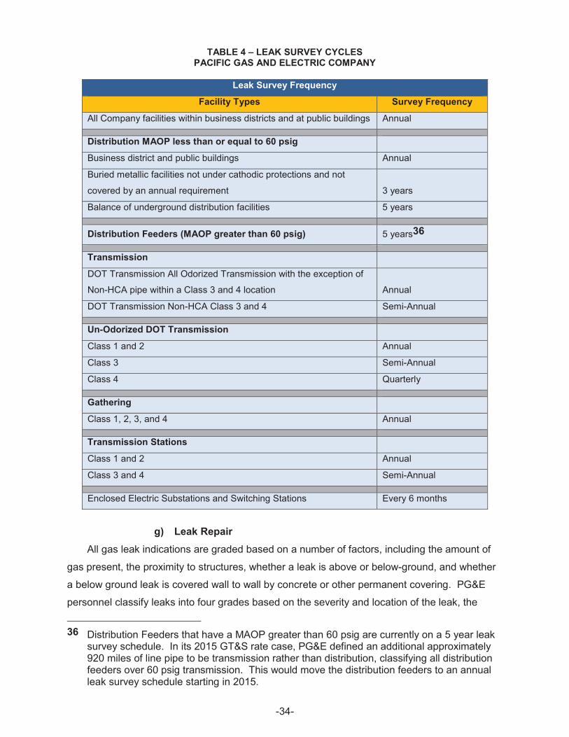
TABLE 4 – LEAK SURVEY CYCLES PACIFIC GAS AND ELECTRIC COMPANY
Leak Survey Frequency
Facility Types Survey Frequency
All Company facilities within business districts and at public buildings Annual
Distribution MAOP less than or equal to 60 psig
Business district and public buildings Annual
Buried metallic facilities not under cathodic protections and not
covered by an annual requirement 3 years
Balance of underground distribution facilities 5 years
Distribution Feeders (MAOP greater than 60 psig) 5 years36
Transmission
DOT Transmission All Odorized Transmission with the exception of
Non-HCA pipe within a Class 3 and 4 location Annual
DOT Transmission Non-HCA Class 3 and 4 Semi-Annual
Un-Odorized DOT Transmission
Class 1 and 2 Annual
Class 3 Semi-Annual
Class 4 Quarterly
Gathering
Class 1, 2, 3, and 4 Annual
Transmission Stations
Class 1 and 2 Annual
Class 3 and 4 Semi-Annual
Enclosed Electric Substations and Switching Stations Every 6 months
g) Leak Repair All gas leak indications are graded based on a number of factors, including the amount of
gas present, the proximity to structures, whether a leak is above or below-ground, and whether
a below ground leak is covered wall to wall by concrete or other permanent covering. PG&E
personnel classify leaks into four grades based on the severity and location of the leak, the
36 Distribution Feeders that have a MAOP greater than 60 psig are currently on a 5 year leak survey schedule. In its 2015 GT&S rate case, PG&E defined an additional approximately 920 miles of line pipe to be transmission rather than distribution, classifying all distribution feeders over 60 psig transmission. This would move the distribution feeders to an annual leak survey schedule starting in 2015.
-34
hazard the gas leak presents to persons or property, and the likelihood that the leak will become
more serious within a specified amount of time.
x Grade 1 leaks (also referred to as “hazardous” leaks) represent existing or probable
hazards to persons or property and require immediate repair or continuous action
until conditions are no longer hazardous.
x Grade 2+ (Priority Grade 2) leaks fall below Grade 1 criteria and above Grade 2
criteria. These leaks are non-hazardous to persons or property at the time of
detection, but still require a scheduled priority repair within 90 days or less.
x Grade 2 leaks are non-hazardous to persons or property at the time of detection,
but still require a scheduled repair because they present probable future hazards.
Grade 2 leaks must be repaired within 15 months, and rechecked every six months
until repaired.
x Grade 3 leaks are non-hazardous at the time of detection and can reasonably be
expected to remain non-hazardous. They are re-surveyed and monitored annually,
or no later than 15 months, but historically not scheduled for repair (unless leak
indications change which qualifies the leak as a Grade 1, Priority Grade 2 or
Grade 2 leak).
PG&E’s grading rules exceed industry standards, as set by the ASME Gas Piping
Technology Committee Guide for Gas Transmission and Distribution Piping systems, in that
PG&E uses a Grade 2+ category with a scheduled priority repair within 90 days.
PG&E has a trained and operator-qualified workforce that finds and repairs leaks using
acceptable industry repair methods and procedures. While some leak repair work is completed
on above ground facilities, many leak repairs require excavation to below the surface
infrastructure facilities. All work performed is documented for completeness.
PG&E is now responding to leaks faster than ever before – and surpassing industry
averages. As of July 2014, PG&E’s average response rate to calls from customers reporting
gas odors was under 20 minutes, and industry benchmarking shows that PG&E has moved
from the bottom quartile to one of the top responders in the country.
h) Pipeline Patrol and Monitoring Pipeline Patrol and Monitoring involves Operator-Qualified personnel visually inspecting
transmission pipelines, and select distribution facilities. Patrolling is conducted either aerially or
on the ground to provide continuing surveillance of abnormal operating conditions and potential
threats to pipeline integrity on or near the pipeline. Patrolling includes, but is not limited to,
monitoring excavations near pipelines, and reporting vegetative and structural encroachments
-35
that may impede transmission pipeline access. Exceeding federal requirements,37 PG&E’s
Pipeline Patrol Program seeks to conduct patrols on a monthly basis.38 PG&E also performs
patrols of pipelines located in High-Consequence Areas twice each month, as well as special
patrols following natural disasters or other incidents as necessary.
PG&E revised its patrol work procedure in August 2012, in response to the Root Cause
Recommendations made by the then-CPSD as part of the Class Location Order Instituting
Investigation (I.11-11-009). In adherence to the revised procedure, all personnel who continued
or began patrolling underwent new, mandatory training and were required to hold additional
Operator Qualifications (OQ), one of which was revised for the new program. Additional
program improvements were implemented during 2013, which included the institution of a
dedicated aerial observer (to accompany the pilot), the utilization of mobile tablet technology for
recording aerial observations, the review of video captured during aerial patrol flights as a
Quality Control (QC) measure, the creation of a catalog for persistently-reported
encroachments, and a streamlining of the aerial observation follow-up process. These
enhancements prompted another revision of the patrol work procedure, which took effect on
January 1, 2014. Ground patrollers were retrained and re-qualified by June 30, 2014, in order
for them to continue patrolling. Forthcoming improvements include the incorporation of
improved pipeline location data from the Pipeline Centerline Survey (see discussion below), as
well as the comparison of persistently-reported encroachments with Land Management’s data
as a Quality Assurance (QA) and control measure.
I) Pipeline Markers 49 CFR §192.707 requires PG&E to provide line markers and warning information for select
gas pipelines. Pipeline markers and indicators39 are used to indicate the approximate location
of the respective pipeline along its route, which contributes to public awareness and damage
prevention. The markers are signs on the surface above or near the natural gas pipelines
located at frequent intervals along the pipeline right-of-way. The markers can typically be found
37 Per 49 C.F.R. §192.705, Class 1 and 2 transmission pipelines must be patrolled at least annually; Class 3 transmission pipelines must be patrolled at least two times per year; Class 4 transmission pipelines must be patrolled at least quarterly. Per 49 C.F.R. §192.721, patrols of distribution pipelines “in places or on structures where anticipated physical movement or external loading could cause failure or leakage” are required at least quarterly for such pipelines in business districts, and at least twice per year for such pipelines outside of business districts.
38 PG&E has committed to patrol select pipelines more often than required by federal code. 39 Pipeline indicators are PG&E’s term for objects that inform about the location of the pipeline
but do not meet the federal code’s text lettering and spacing requirements (e.g., one inch high, with ¼-inch stroke) to be formally considered markers.
-36
at various points along the pipeline route including highway, railway, and waterway
intersections. These markers display the name of the operator and a telephone number where
the operator can be reached in the event of an emergency.
PG&E’s Procedure “Gas Pipeline Markers and Indicators” outlines PG&E’s process for
installing and maintaining pipeline markers in compliance with state and federal requirements.
A revision to this procedure was published on September 18, 2013, to account for program
improvements including the addition of a more durable and visible Tri-View™ marker, the
implementation of additional pipeline indicators to further identify the presence of a pipeline in
locations where markers may be impractical, and the implementation of pipeline marker and
indicator installation forms to allow installation data to be recorded and absorbed into the
system of record. As part of the Pipeline Centerline Survey (discussed in next section),
approximately 12,000 pipeline markers were installed from July 2013 to March 2014.
II) Pipeline Pathways Pipeline Pathways is a multiyear program that is designed to enhance safety by reducing
risk to the integrity of the transmission pipelines, and improving access to PG&E rights-of-way.
In 2014, PG&E’s main effort is focused on identifying and removing structures and non-
compatible vegetation above and around the pipelines that represent potential risks to safety.
PG&E implements the Pipeline Pathways program through various projects, which are listed
below:
x Pipeline Centerline Survey – This project included surveying 6,750 miles of gas
transmission pipeline by using precise mapping tools with Global Positioning
System (GPS) coordinates, and entering the GPS coordinates into a new GIS.
This project was completed in December 2013 and allows PG&E to accurate locate
and monitor its gas transmission pipelines.
x Encroachment Clearance – This project includes locating, staking, and mapping
the center of the pipeline, and checking the area above the pipeline for any
structures or vegetation that could interfere with PG&E’s ability to maintain, inspect,
and safely operate the pipeline. This is followed by remediation of any such
encroachments deemed unacceptable for the safe maintenance and operation of
the pipeline. The main focus in 2014, is removing structures and trees from PG&E
rights-of-way. PG&E is working with home owners and cities on these efforts to
identify the best solutions.
-37
x Vegetation Management – This project is focused on keeping PG&E’s
right-of-way open and free of “non-compatible vegetation.” Along with structure
clearing, this improves our ability to respond in emergency situations
x Pipeline Marker Installation – PG&E is increasing the number of pipeline markers
on transmission pipelines to enhance public awareness and damage prevention
while increasing safety activities around pipelines by providing a clear line of sight.
This project was completed in March 2014. PG&E is continually monitoring and
maintaining its pipeline markers.
The efforts under the Pipeline Pathways program strengthen PG&E’s ongoing pipeline
safety programs, improve the ability to identify and prevent risks to our pipelines, and give
PG&E better access to inspect, test, and maintain pipelines.
i) Cyber Security To address the threat from cyber security (Risk #6 in Table 3 above), PG&E must
proactively invest in ensuring effective controls in order to reduce risk and maintain the
resiliency of our critical infrastructure. PG&E must endeavor to prevent when possible—and
adapt to, withstand, and rapidly recover from when necessary—risks such as:
x Intrusions (physical or cyber)
x Attacks (physical or cyber)
x Disasters (natural or man-made)
x Accidents (natural or man-made)
x Changing conditions and other incidents
PG&E has a Gas Cyber Security Program that will strengthen its Gas Operations
Transmission Data Network, through the development of various tools, procedures, and
programs that are described below as part of Gas System Operations and Control. This project
is being coordinated with other Cyber Security programs and projects that are being developed
in PG&E.40
b. Mitigating Loss of Supply a) System Pressure and Capacity
PG&E designs and operates its gas system to ensure safe pressure regulation and
adequate gas supplies. A focused plan for pressure regulation includes extensive data
40 See PG&E’s 2015 GT&S rate case testimony Chapter 11 for an in-depth discussion on PG&E’s cyber security programs.
-38
gathering, root cause analysis of any over pressure event, and a corrective action and
improvement plan that includes evaluating equipment set points and Supervisory Control and
Data Acquisition (SCADA) alarm points.
PG&E’s pipeline capacity is sized to provide all core41 customers with uninterrupted
service on a one-day-in-90-year cold temperature design day (referred to as an Abnormal Peak
Day), and to provide all customers, including noncore,42 with uninterrupted service on a
one-day-in-two-year design day (referred to as a Cold Winter Day). Abnormal Peak Day and
Cold Winter Days are based on conditions that have actually occurred on PG&E’s system within
those respective time spans.
Customers value service reliability and there can be significant public health and safety
risks associated with insufficient capacity. A lack of pipeline capacity could lead to a loss of gas
service that customers depend on for daily life activities including space heating, water heating,
and cooking. In very cold weather, loss of space heating can itself be life-threatening, and can
prompt customers to use unsafe heating alternatives such as outdoor grills and barbecues.
Loss of gas service can also lead to extinguished pilots and the subsequent potential for
uncombusted gas entering affected buildings. In some scenarios, loss of gas service can affect
electric generation, which during very hot weather can also result in safety concerns.
PG&E’s pipeline capacity planning requirements are outlined in Standard “Gas
Transmission and Distribution Systems Capacity Planning Requirements.” The standard is
supported by a companion document, “Gas Transmission and Distribution Systems Capacity
Planning Procedures.” Under the framework provided in these procedures, PG&E routinely and
systematically studies its storage, transmission, and distribution systems, to ensure capacity is
adequate to meet design day criteria. PG&E’s Gas System Planning Department obtains
information from a variety of sources, including operational data, other PG&E departments,
government agencies, planning commissions, regulatory proceedings, and news reports to
determine possible load growth and other potential changes that may affect system capacity
requirements. In addition, systems are studied as needed to ensure that planned pipeline
operations such as ILI, pressure-testing, maintenance, and repair are managed for minimum
impact on capacity.
PG&E assures the quality of its planning effort through a matrix of tools, processes,
personnel, standards, and documentation that provide the appropriate level of oversight and
control to its management team.
41 Core Customers include residential and small commercial. 42 Non-Core Customers include large commercial, industrial or institutional.
-39
In 2013, Gas System Planning launched its Network Investment Plan program.43 Under
this multi-year program, Gas System Planning will analyze PG&E’s many gas systems in a
long-term, holistic manner to optimize system design. The objective is to ensure that the
various safety-related pipeline efforts including pipe replacement, ILIs, hydrotests, valve
automation, and station work are incorporated efficiently into design work driven by other factors
such as future growth over a ten to twenty-year time horizon. This long-term planning effort is
also intended to wring out any existing design inefficiencies such as multiple short-run diameter
changes that inhibit piggability and potential safety risks such as excessive manual winter
operations and operating with little margin of safety against overpressure events. PG&E has
completed eight investment plans, 4 are near complete, 2 are in progress, and 12 more will be
started later in 2014.
b) Overpressure Elimination Initiative Pressure is a significant driver of pipeline capacity, so it is necessary to conduct hydraulic
studies on each system to ensure that design day criteria can be met at the proposed regulator
set point. In 2012, PG&E began an initiative to eliminate unintentional system overpressure
events above MAOP. This program has focused on establishing an even greater operating
margin between system normal operating pressure and system MAOP, putting standards and
procedures in place to eliminate operating errors and looking for and resolving recurring
equipment issues that can lead to system overpressure events. The results of the program
have reduced overpressure events on the system from 774 in 2011 to a total of 31 in 2013.
Only 11 overpressure events have occurred year-to-date (end of July 2014), compared to an
annual goal of 24 or fewer events. In 2014 and 2015, the program focus will be improvements
in clearance development and adherence, improvements in procedures on manual operations
and further work on equipment performance improvement.
Similarly, PG&E has evaluated and reduced pressures in its gas distribution systems where
possible to provide increased separation between pressure control set points and maximum
operating pressures.
c) Operations Clearance Procedures An important part of public safety is ensuring that the company uses a clearance procedure
for gas operations. Clearance procedures are an added safety step to confirm that a plan and
procedure is in place before work is performed. The Transmission Clearance Procedure is used
for work that impacts gas flows, pressures, or gas quality. If a transmission facility is to be taken
43 See Chapter 10 of PG&E’s 2015 GT&S rate case for an in-depth discussion on the Network Investment Plans.
-40
out of service for repairs, a plan and procedure (“clearance”) must be formalized in writing and
reviewed by the field and engineering personnel scheduled to perform the work. Transmission
system clearances are managed and approved by Gas Transmission Control.
For distribution, PG&E is in the process of developing the Distribution Clearance Procedure
which will help eliminate work performance errors, unplanned outages, and at-fault dig-in events
through a centralized review of pending work. In essence, all work associated with gas
distribution facilities will require approval and/or situational awareness from the Distribution
Control Center for activities impacting the gas network. Field personnel will call the control
room to report a clearance and technology will be used for situational awareness of employees
performing non-clearance activity.
Industry best practices are being adopted for both the Distribution Clearance Procedure
and the Transmission Clearance Procedure. PG&E has developed an electronic tool to
administer its clearance procedures for both Transmission and Distribution. The Transmission
electronic tool was phased in during 2014. The Distribution electronic tool completed its pilot
phase and will be on a roll-out schedule through 2015. Both electronic tools have been
designed to insure the clearance process is executed in a thorough, consistent, and
visible manner.
d) Supplier Quality for Distribution and Transmission Gas Products Supplier QA establishes procedures, practices, and expectations, pertaining to the quality
of transmission and distribution products purchased by PG&E. The requirements set forth
assure consistent quality based on processes for supplier approval, product approval, receiving
inspection, supplier audits, product nonconformance resolution, and supply base scorecards for
key suppliers.
The programs that comprise the overall quality system are varied, inter-related and
generally involve engagement activity from materials personnel, field personnel, standards
engineering, purchasing personnel as well as quality engineers and inspectors.
Distribution Gas Products For the distribution system, PG&E maintains a database of all products that have been
identified by standards engineering as safety significant. These products have inspection plans
that are routinely reviewed for updates based on revisions to the associated engineering
standards. All products that require inspection are inspected according to the documented
inspection plan. No nonconforming product is allowed into stock.
If a product fails at receiving inspection or in the field and that failure appears to be part of a
trend or may be repetitive, PG&E Supplier Quality Engineers work directly with the manufacturer
-41
to resolve the issue through root cause analysis and corrective action plans. The
non-conformance issues are identified and documented in the Material Problem Reporting
system. Supplier QA manages the Material Problem Reporting system which is available to all
personnel at PG&E to allow employees to document any defective or suspect defective material
including tools and gas carrying products (material problem reporting is discussed in
Section III.B.3).
If it is determined the nonconformance issue may be related to the supplier, then a Supplier
Corrective Action Request is issued requiring product containment and a corrective action plan.
A Supplier Quality Engineer will determine if the supplier’s response and corrective actions are
adequate. All key suppliers have their quality performance measured on a continuous basis.
The measurement process is an industry recognized system called Defective Parts Per Million
(DPPM). All new suppliers, production products, and tooling must first be approved by a team
review of their quality processes per PG&E’s standards.
Transmission Gas Products The Supplier QA procedures and systems for procured transmission products is the same
as for distribution products except in the area of inspections. Transmission products do not
pass through a PG&E receiving location and therefore a receiving inspection is not performed.
Instead, all transmission products undergo source inspection at the supplier’s site. Due to the
difference in the inspection location, a DPPM score is not produced because is not accessible
from the inspection site.
c. Mitigating Inadequate Response and Recovery PG&E’s policies and procedures have been revised to provide effective system controls for
both equipment and personnel to limit damage from accidents, explosions, fires and dangerous
conditions. It is PG&E’s policy to:
x Plan for natural and manmade emergencies such as fires, floods, storms,
earthquakes, cyber disruptions, and terrorist incidents;
x Respond rapidly and effectively, consistent with the National Incident Management
System principles, including the use of the ICS, to protect the public and to restore
essential utility service following such emergencies;
x Help alleviate emergency related hardships; and
x Assist communities to return to normal activity.
-42
All PG&E emergency planning and response activities are governed by the following
priorities:
x Protect the health and welfare of the public, PG&E responders, and others;
x Protect the property of the public, PG&E, and others;
x Restore gas and electric service and power generation;
x Restore critical business functions and move towards business as usual; and
x Inform customers, governmental agencies and representatives, the news media,
and other constituencies.
The next sections discusses programs in place to mitigate threats the have the potential to
prevent PG&E to respond in a timely manner.
a) Gas System Operations and Control PG&E’s Transmission and Distribution Gas Control Centers monitor and control the flow of
gas across our system 24 hours a day, 365 days per year, to ensure that it is received and
delivered safely and reliably to customers. PG&E utilizes an operational manual that contains
the necessary documents for control room personnel to manage and operate the gas
transmission and distribution systems, in accordance with the requirements outlined under
49 CFR 192.631, Control Room Management (CRM). PG&E’s CRM manual contains the
standard, procedures, plans, and processes that collectively address how the gas control room
personnel conduct their work activity under normal, abnormal, and emergency operating
conditions. The CRM manual has six over-arching procedures: (1) Information Management;
(2) Fatigue Mitigation; (3) Alarm Management; (4) Management of Pipeline Changes;
(5) Evaluating Operational Experience; and (6) Gas Control Training Program.
PG&E has also completed development of a software application to create a bridge
between the SCADA alarm system and the OSIsoft PI Historian to improve situational
awareness and provide greater capability to track and analyze alarm information.44 Billions of
data records have been loaded into the OSIsoft PI Data Historian system representing more
than a decade of historic SCADA information. New data is being added to the OSIsoft PI Data
Historian system continuously, within seconds of being recorded in the SCADA system.
This platform is being utilized to rapidly provide near real-time information to Gas Control
and planning areas of the Gas Operations organization with plans to expand its use to
engineering and maintenance areas. This will provide better guidance and input for remote
44 In late December 2011, PG&E completed a SCADA enhancement that prioritizes alarms for appropriate operator action upon activation. This SCADA modification project provides PG&E’s operating team the capability to filter alarms based on priority, data type, and geographic location. Alarm priorities can now be configured based on four categories: Emergency, High, Medium, and Low.
-43
monitoring and controls, as well as for real-time operations. PG&E is using the real-time
OSIsoft PI Data Historian platform to support creation of various situational awareness screens.
I) Transmission Control Center The Transmission Gas Control Center monitors and controls system pressure, flow and
operation status utilizing approximately 10,000 SCADA points, providing oversight of all
compressor stations, storage fields, pipeline interconnections, and other key pipeline facilities.
Gas Transmission Control operators can control system flows and pressures utilizing
approximately 800 supervisory control points. In addition, the SCADA system continually
provides calculated data for approximately 3,000 other points representing system inventory,
supply and demand information on the transmission system.
The SCADA system utilizes alarms to warn Gas Transmission Control of changing
conditions that could escalate to abnormal or emergency conditions and provides prioritization
functionality. The system provides alarm filtering based on priority, data type, and geographic
location to facilitate appropriate operator action upon alarm activation. Alarm priorities are
configured based on four categories: Emergency, High, Medium, and Low. PG&E also has a
geographical based operating process which allows for assignment of operator responsibilities
based on “north” and “south” service territory assignments.
II) Distribution Control Center PG&E’s gas distribution system covers an area of 58,000 square miles, with
826 hydraulically independent systems. Real-time distribution oversight is provided by Gas
Distribution Control at approximately 292 continuously monitored distribution locations at district
regulator stations and pipelines. In addition, some local distribution oversight is enabled by
approximately 350 electronic recording devices which alert local on-call distribution supervisors
if pressure set points are exceeded. Should an electronic recording activate, the local
distribution supervisor is responsible for assessing the nature of the alert and, if appropriate,
dispatching PG&E personnel to address the situation. To monitor the balance of the distribution
system, local offices collectively deploy more than 500 permanent and temporary chart
recorders45 to record pressure data.
PG&E installed 417 monitoring and control devices across the gas distribution service area
in 2013 and plans to install approximately 3,500 devices from 2014 through 2020, for a total of
45 A chart recorder uses paper charts to record system pressures over time; typically 30 days. These are then used by engineering personnel to analyze historic usage and to forecast future capacity needs.
-44
3,900 devices. Over time, the number of field monitoring locations will provide over 95 percent
visibility of the distribution network.
b) Enhancements to Transmission and Distribution Control Centers In the 3rd quarter of 2013, PG&E opened a new state-of-the-art gas control facility to
monitor and manage its entire gas system. The new facility co-located Gas Transmission
Control Center, Gas Distribution Control Center and Gas Dispatch functions into a single facility
operating 24-hours a day. The co-location of these three functions enables the company to
increase system knowledge and situational awareness to provide superior emergency response
coordination and facilitates better communication, information sharing and monitoring.
The control centers have sufficient physical infrastructure redundancy such that no single
point of infrastructure failure will affect operations. Key features of the facility design include:
x Backup power supplied by a second service line to provide two independent paths
for power to critical systems
x Standby power supplied by two diesel generators outside of the facility
x Two uninterruptible power systems to provide protection from electrical faults
x An independent Heating, Ventilation and Air Conditioning (HVAC) system for the
control room, with the building’s HVAC serving as backup
c) Valve Automation PG&E’s Valve Automation Program is designed to enhance emergency response in the
event of a gas transmission pipeline rupture. This program builds upon the scope, principles
and decision trees that the Commission approved in D.12-12-030 as part of PG&E’s PSEP. In
D.12-12-030, the Commission approved the plan to replace, automate, and upgrade 228 gas
shut-off valves from 2011-2014. The valve automation plan is subject to permitting and weather
clearances, which will defer some valve automation projects to 2015.
This automation program will result in approximately 504 miles of additional gas
transmission pipeline that can rapidly be isolated through remote control valve technology.
Installation of automated isolation capability on major pipelines in heavily populated areas
increases emergency preparedness, and may reduce property damage and the danger to
emergency personnel and the public in the event of a pipeline rupture.46
46 See Chapter 4A of PG&E’s 2015 GT&S rate case for an in-depth discussion on the Valve Automation.
-45
d) Emergency Response I) Company Emergency Plan
PG&E’s Company Emergency Plan (CEP) (Attachment 11) provides a broad outline of
PG&E’s organizational structure and describes the activities which will be undertaken in
response to emergency situations. The CEP will be used during emergencies by presenting a
response structure with clear roles and responsibilities and identifying coordination efforts with
outside organizations (government, media, other electric and gas utilities, essential community
services, vendors, contractors).
Details of how PG&E accomplishes the functions described in the CEP are found in topic-
specific plans prepared by the individual departments and LOB. PG&E maintains over
18 Emergency Operation Plans (EOP) for the various organizations, including the Gas
Emergency Response Plan (GERP) (Section VII.B.1 of the CEP), which provides detailed
information about PG&E’s planned response to gas transmission and distribution emergencies.
These individual EOPs are updated annually. In addition to the EOPs, PG&E maintains
approximately 48 Business Continuity Plans, which describe how PG&E will continue essential
business operations in the event of a disruption to facilities, technology or personnel.
PG&E also utilizes the ICS, which is a systemic tool used for the command, control, and
coordination of emergency response. The ICS provides a systematic, proactive approach for all
levels of governmental and nongovernmental organizations and the private sector to work
together during an incident to reduce the loss of life, damage to property and harm to the
environment. It also gives a clear understanding of managing an incident with the use of an
Incident Action Plan. The Incident Action Plan focuses on clarifying the situation, establishing
incident objectives and strategy, developing a plan, preparing and disseminating the plan,
executing the plan, and evaluating and revising the plan, and finally demobilization.
A) Response to Emergency Events To ensure a consistent and well-coordinated response to emergencies, the company has
developed the following emergency classification system known as PG&E Incident Levels:
x Level 1 – Routine: These incidents involve a relatively small number of
customers, such as those managed during routine operations. Local resources
are sufficient to respond. This level does not require the activation of an
emergency center.
x Level 2 – Elevated: This is a pending potential incident or a local emergency that
requires more than a routine operations response. Resources are mainly local, but
there is a possibility that resources may need to move within the region.
-46
Emergency Center activation includes: Operations Emergency Center (OEC)
Communications Only, OEC activation is possible.
x Level 3 – Serious: This serious incident involves large numbers of customers.
Resources mainly move within the region, but may need to move between regions.
Emergency Center activation: OEC activation, Regional Emergency Center (REC)
and Emergency Operations Center (EOC) activation possible.
x Level 4 – Severe: This is an escalating incident with company impact/extended
multiple emergency incidents that impact a large number of customers. Resources
move between regions, general contractors are utilized, and mutual aid may be
needed. Emergency Center activation: OEC, REC and EOC are activated.
Incident Support Team (IST)47 activation is possible.
x Level 5 – Catastrophic: This is a catastrophic event that includes multiple
emergency incidents, impacts a large number of customers, has a significant cost,
and significant infrastructure risk/damage. This level of emergency affects the
company and its ability to conduct business operations. The full mobilization of
company resources is needed to respond, and mutual aid resources are needed.
Emergency Center activation: OEC, REC, EOC, IST activated.
The OEC and REC are emergency centers that manage the work in a defined geographic
region, and are responsible for directing resources to implement actions and for reporting status
and progress through the Emergency Center chain of command, ultimately to the EOC. The
EOC is a designated location at which key personnel meet to coordinate or command response
to an emergency. The EOC is equipped with all necessary equipment, supplies, information
and data systems, backup power, and other resources needed to conduct prompt and effective
emergency response activities. The EOC has a designated backup facility in the event that the
primary EOC is not available or accessible.
PG&E’s Incident Levels help support PG&E in understanding the complexity of an incident
and the actions that may be employed at each level (e.g., emergency center activations,
resources needed, etc.).48
47 The mission of the IST is to support the execution of the incident response. The IST membership is made up of the LOB senior operating executives who maintain a comprehensive view of the response and affirm that the EOC Commander’s restoration priorities and incident objectives are being effectively carried out. The IST further supports the EOC Commander by making policy decisions and removing roadblocks that may affect restoration and recovery. The IST is activated by the VP of EP&R and may convene via conference call or in person.
48 See Attachment 11 for more discussion of the CEP.
-47
II) Gas Emergency Preparedness and Response The Emergency Preparedness and Public Awareness (EP&PA) Department in Gas
Operations supports coordination activities, training, and communication with city/county/local
first responders within PG&E’s service territory. A primary function of the EP&PA department is
to provide pipeline and general safety training to local/state/volunteer first responders, as well
as share the GERP with the appropriate community partners. The EP&PA department is
actively engaged in incident response, all facets of emergency preparedness planning, training
(for both internal and external responders), performance measurement, and regulatory
compliance. Responsibilities of this department include maintenance of the GERP to assist
PG&E personnel in responding safely, efficiently, and in a coordinated manner to emergencies
affecting gas transmission and distribution systems. Additionally, the EP&PA department
coordinates After Action Reviews of gas incidents and exercises, holds program responsibility
for Gas Operations Business Continuity Plans, designs and facilitates functional/field and
tabletop exercises and drills, and participates in industry benchmarking on Emergency
Management solutions and best practices.
An example of a drill PG&E conducts is its annual company-wide emergency drill, which
was held on May 14 and 15, 2014. The exercise, called the Hayward Fault scenario, was a
7.0 magnitude earthquake, on the Hayward Fault, centered in San Pablo Bay. The scenario
spanned twelve-hours over two days and was designed to test several newly written emergency
response plans, including communication capabilities, conduct damage assessment, use
damage modeling to identify resources needed for restoration, ability to integrated a gas and
electric response, and set up a base camp to effectively move crews throughout the simulated
damaged area. Core capabilities that were used to achieve objectives were: Planning,
Situation Awareness, Operational Communications, Public and Private Services and
Resources, and Operational Coordination. Participants in this two-day event included local and
state regulators, emergency responder teams, other public agencies, and PG&E.
The GERP (Attachment 12) describes the roles and responsibilities of PG&E’s emergency
response personnel, which include a single person who assumes command and designates
specific duties for the SCADA staff and all other potentially involved company employees.
PG&E’s 911 Notification Process requires PG&E’s control room operators to make the
911 notification immediately based on the following SCADA alarm conditions:
x Relief valve open alarm venting gas to atmosphere;
x Automatic shut off valve closed alarm indicating isolation of a section of pipeline;
x Activation of a pressure drop – rate high alarm indicating a high differential
across one of the newly installed remote control isolation valves; and
-48
x Activation of a Lo-Lo pressure alarm indicating possible pipeline rupture
(confirmed valid by verification of upstream and downstream pressure sites and
correlated supply source metered flow increase).
Once SCADA alarm conditions have been triggered, and/or non-SCADA based information
has been received suggesting an emergency operating condition, PG&E follows a detailed
procedure that explicitly requires Gas Control to notify 911 Emergency Response Centers. The
PG&E 911 Notification Process includes triggers to immediately make 911 notifications
concerning a transmission or distribution facility involvement in a natural gas related event.
In order to improve focus on real time monitoring, PG&E has implemented geographical
based responsibilities for gas system operators. Transmission control operators are assigned to
monitoring north or south portion of the system. For distribution control, the assignments are
broken out by Northern, Bay, Central Coast, and Central Valley. At any given time, operators
are now responsible for monitoring their assigned areas only (see control room discussion in
Section II.B.4.b.b).).
Additionally, PG&E has a fleet of new Mobile Command Vehicles to respond more rapidly
to natural gas or electric emergencies. PG&E has six Mobile Command Vehicles and
four Emergency Communication Trailers, which are used with the Mobile Command Vehicles to
boost the radio signals.
III) Earthquake Response PG&E uses GIS based products to enhance emergency response following a significant
earthquake. PG&E’s Gas Transmission Earthquake Plan and Response Procedure is provided
in Risk Management Instruction (RMI) – 04 (Attachment 13) and the Gas Distribution
Earthquake Plan is provided in RMI- 04B (Attachment 14). These plans describe PG&E’s use
of United States Geological Survey data and identify service areas that are potentially impacted.
The susceptibility to seismic activity and geotechnical conditions is reviewed annually, and
updated to provide accurate response areas over PG&E’s Service Territory.
The GERP provides guidance and information for responding to earthquake emergencies
(Appendix A.2. Training Aid 7 – Earthquake, see Attachment 13). PG&E has also updated the
Earthquake Playbook (EMER-1012M) (Attachment 15), to provide guidance on PG&E’s
response and recovery actions. The Earthquake Playbook provides an executiveǦlevel
perspective on disaster conditions the company will face immediately after an earthquake,
including actions it will take and how it will conduct business
-49
IV) Information for First Responders and the Public PG&E launched a web portal within pge.com dedicated to external first responders and
residential customers. Access to training materials, general mapping of gas transmission
pipeline segment locations, safety DVDs, and literature on school safety is available, along with
other information and resources for gas emergency response. Enhancements have been made
to some of the data available to first responders so that they can use it in real time while
en-route to an incident or once they have arrived on scene. For example, registered
first responders now have access to more detailed characteristics of gas transmission assets,
portions of the GERP, and contact information to key members of the EP&PA department.
PG&E has developed specific informational flyers and has issued press releases to
promote safety (such as for dig-ins which potentially damage infrastructure and for customer
behavior around potentially dangerous infrastructure including downed power lines). These
materials are accessible through pge.com and a special safety education website at
www.pge.com/safetycentral.
V) Call Center PG&E operates a 24/7 Contact Center to receive calls from customers and emergency
responders. All Contact Center representatives receive an annual training on gas emergency
response procedures. Related call handling processes are housed in an online repository that
is utilized by Contact Center representatives to ensure adherence to public safety and
emergency procedures during any event of a gas emergency, pipeline integrity situation or
threat to public safety. The Gas Dispatch Center is notified immediately of any emergency gas
situation that is called into the Contact Center.
VI) Response to Customer Odor Calls PG&E’s response to customer calls to gas odors was in the top decile performance of
benchmarked utilities last year. PG&E has responded to 99.6 percent of all gas emergency
response calls within 60 minutes and on average responded in 20.0 minutes year-to-date 2014.
C. Compliance 1. Codes, Standards, Policies, and Procedures
PG&E has numerous standards, policies, and procedures in place to support Gas
Operations, and to ensure work performed by employees and contractors is done safely and
consistently. PG&E’s gas standards, including Operations and Maintenance procedures, are
developed to comply with federal and state pipeline safety regulations. The Regulatory
Compliance organization monitors and tracks changes to legislation and regulatory
-50
requirements to ensure timely implementation. The Standards and Procedures organization is
responsible for documenting changes so that policies, standards, procedures, practices, and
training materials are updated, in a timely fashion to meet federal and state requirements.
PG&E follows its gas guidance document development and update process to publish its
documents. Published documents have assigned SMEs that perform assessments of guidance
documents to determine the need for developing or altering the document. PG&E’s gas
guidance documents are defined as follows:
x Policy: Provides high-level, broad instruction about a significant business
operation, subject or function, consistent with laws and regulations, the company’s
vision, values, and goals, and any direction from the Boards of Directors.
x Standard: Describes the major steps of a work process and/or major internal or
external compliance requirements, and the roles and responsibilities of those
involved. A standard may involve one or more organizations, departments, job
functions, or compliance requirements. A standard can be a stand-alone document
or incorporated in a manual with implementing procedures and other related
information, e.g., forms, drawings, or specifications.
x Procedure: Detailed, step-by-step instruction that describes the functions, tasks,
and expectations of employees who are responsible for performing a specific
function or task. A procedure includes or refers to all safety, health, and
environmental instructions that an employee needs to perform the work correctly.
A procedure can be a stand-alone document or incorporated in a manual with
governing standards and other related information, e.g., forms, drawings, or
specifications.
x Bulletin: A brief, interim, and temporary guidance document designed to heighten
awareness of a particular issue, usually one or more of the following: an immediate
change in how business is done and/or information about a safety, health or
environmental incident or issue and resulting required actions, and/or information
about a new mandatory compliance requirement, and/or a clarification of a previous
instruction (“how-to” instruction often is included). As soon as practicable, the
document owner incorporates the bulletin information into the parent policy,
standard, or procedure and cancels the bulletin.
PG&E also has gas technical teams comprised of cross-functional representatives that
assure the standards, procedures, tools, and technologies used in specific areas remain current
and updated. The technical teams are made up of a cross section of employees representing
-51
technical SMEs, field representatives who perform the work, training experts, those responsible
for evaluating employee qualifications, and those who perform related engineering, design and
records activities. Major duties of the technical teams include:
x Identifying issues and resolutions
x Identifying documents
x Writing and/or revising guidance documents
x Approving documents
x Approving products
x Identifying training
x Evaluating best practices or processes used by other utilities.
To ensure the standards, procedures, tools, and technologies are current, PG&E maintains
gas technical teams as shown in Attachment 16. Gas technical teams provide support,
recommendations, evaluations, and user feedback on the performance, operation,
maintenance, development, and implementation.
Work quality field assessments are conducted using published work procedure documents
to ensure the document is being followed and to identify further areas of opportunity. Findings
and identified deficiencies in the documents are provided to the appropriate technical team for
evaluation and revisions.
Published documents currently in effect are posted to PG&E’s Technical Information Library
to allow for broad access by employees. Based on employee feedback a 24/7 helpline was
created to support employees in finding documents and in obtaining technical clarification to
standards and procedures. The helpline is staffed by engineers who are responsible for the
standards document content.
a. Code Compliance The State of California’s rules governing the design, construction, testing, operation, and
maintenance of gas transmission and distribution pipeline systems are specified in
Commission’s General Order (GO) 112-E. The Commission has incorporated 49 CFR,
Parts 190, 191, 192, 193, and 199, which govern the design, construction, testing, operation,
and maintenance of Gas Piping Systems into its GO 112-E.
PG&E has developed and implemented policies, procedures and programs that govern the
design, construction, installation, operation, maintenance and determination of MAOP for gas
transmission and distribution facilities in accordance with GO 112-E. These policies,
procedures and programs are updated in a timely manner as appropriate in response to
changes in regulation, safety advisories, and other safety information.
-52
To meet compliance with CPUC rulings, PG&E submits recurring compliance reports
regularly to the CPUC. A listing of these reports is shown in Attachment 17. In addition,
ALJ-274 requires natural gas pipeline operators to self-report non-compliances to the CPUC
within 10 days of discovery, and to implement corrective actions to remedy the issues. As part
of this process, PG&E reaches out to employees at all levels of the organization encouraging
them to help identify issues, gaps and non-compliance items. To date, numerous items have
been raised and self-reported to the CPUC and in doing so allows PG&E to identify and make
systemwide improvements.
As a result of ongoing communications to all employees about the need to report, and the
positive recognition of employees who raise issues, PG&E has submitted 10 self-reports as of
June 30, 2014.
Parts (a) through (g) in this section discuss some the code sections PG&E must comply
with.
a) Maximum Allowable Operating Pressure A MAOP is established for each pipeline or piping system. The established MAOP cannot
exceed the maximum pressure allowed by regulatory code as specified in 49 CFR §192.105,
49 CFR §192.611 and 49 CFR §192.619 through 49 CFR §192.623, as applicable. Class
location, design, testing, and operating history are all factors that can limit the MAOP of a
pipeline or system.
The Pipeline Safety, Regulatory Certainty, and Job Creation Act of 2011 became Public
Law 112-90 on January 3, 2012. This law, in part, requires gas transmission operators to verify
that records accurately reflect the physical and operational characteristics of transmission
pipeline in Class 3 and Class 4 locations and Class 1 and Class 2 high-consequence areas and
then confirm the established MAOP.
b) Class Location The Class Location Program is a compliance requirement to ensure that pipelines are
operating within the appropriate class as determined by population density. 49 CFR
Part 192.613 requires that each operator have a procedure for continuing surveillance of its
facilities to determine and take appropriate action concerning changes in class location.
Currently, a majority of the class location changes are identified through the annual class
location study. This study includes orthographically corrected aerial photography, occupancy
field verification, creation of a digitized structures layer, and annual class analysis completed via
a qualified third party firm and that is verified internally. Additionally, changes in class are
discovered through routine pipeline patrols performed by way of fixed wing aircraft, helicopters,
-53
and by pipeline patrol employees on foot. Input may also be provided by other field personnel
during routine preventive maintenance activities along the transmission pipeline system.
PG&E’s Class Location Program is a critical component of PG&E’s gas transmission asset
management program. PG&E is continually improving processes and technology to accurately
identify and map the effects of new construction in order to find and mitigate class location
changes. Mitigation is achieved by strength testing, pipeline replacement or reducing
pressure.49
Also new in 2014 is the application of automated software to analyze Class Locations,
which will minimize the possibility of human error in the manual analysis, and will provide the
capability to determine Class Location changes on an on-going basis, as new structures
are identified.
Consistent with 49 CFR, Part 192.611, if a pipeline class change-up is identified, the MAOP
of the pipeline is reviewed and action is taken to assure the pipeline is commensurate with the
new Class Location. If a segment of pipeline is determined to be non-commensurate with the
new class, but no immediate hazard exists, PG&E will remediate the pipeline by hydro testing,
replacement, or retirement as described in PG&E’s Gas Design Standards. Confirmation or
revision of the MAOP that is required as a result of the study must be completed within
24 months of the change in class location.
When a class change-up is identified on transmission pipe operating above 40 percent
SMYS, 49 CFR, Part 192.609 requires that PG&E immediately initiate a study on the pipeline
segments involved.
c) Design 49 CFR Part 192 Subparts B, C, and D specify the minimum requirements for the material
selection and design of pipe and pipeline components. PG&E’s transmission and distribution
pipelines and facilities are designed with approved materials that have sufficient wall thickness
and/or adequate protection to withstand anticipated external pressures and loads. The pipe and
facilities are also designed with materials of sufficient strength to contain internal pressures plus
appropriate design and/or safety factors. Components, including valves, flanges, and fittings
meet the minimum prescribed requirements specified in the regulations. The design also
includes pressure relief or other protective devices to prevent accidental over-pressurization.
To emphasize professional engineering reviews and focus accountability, all pipeline plan and
profile/section drawings for work on pipelines with a design pressure or future design pressure
greater than 60 psig must be reviewed and stamped by a professional engineer. The engineer
49 The Class Location Program is discussed in detail in Chapter 4B of PG&E’s 2015 GT&S rate case.
-54
(civil or mechanical) must be currently registered in the state of California and competent in
pipeline engineering as designated by the manager responsible for the facilities. All design
work performed by contractors is reviewed by a PG&E employee for quality and compliance.
d) Construction 49 CFR Part 192 Subparts E, F, G and J specify the minimum requirements for the
construction and testing of transmission and distribution facilities, including the welding and
joining of pipe and components as well as the protection of the pipe and facilities from hazards
such as unstable soil, landslides, and other hazards that may cause the pipe to move or sustain
abnormal loads. PG&E’s transmission and distribution pipe and facilities are constructed in
accordance with these requirements.
e) Installation 49 CFR Part 192 Subpart H specifies the minimum requirements for the installation of
distribution service lines, service regulators, and customer meters. These requirements include
specifications pertaining to the location of this infrastructure, protection from damage, and valve
requirements. PG&E’s service lines, service regulators, and customer meters are to be installed
in accordance with these requirements.
f) Maintenance 49 CFR Part 192 Subparts M and I specify the minimum requirements for the maintenance
of transmission and distribution pipe facilities along with the associated corrosion protection
facilities. Maintenance activities include the patrolling of pipeline, performing leakage surveys,
monitoring performance of corrosion protection systems, making repairs, inspection and testing
of pressure limiting and regulating equipment, and valve and vault inspection and upkeep.
PG&E maintains its pipelines and facilities in accordance with these requirements.
g) Operations 49 CFR Part 192 Subparts L and K specify the minimum requirements for the operation of
transmission and distribution pipeline facilities. Operational activities include the Emergency
Response Plan as well as requirements for a public awareness program, damage prevention
program, CRM procedures, odorization of gas, identification of changes in population density
along certain transmission lines, and the determination of MAOP including requirements for
increasing the MAOP. PG&E operates its pipelines and facilities in accordance with these
requirements.
-55
h) Odorization All gas leaving PG&E’s transmission and distribution systems is odorized such that it can
be readily detected at concentrations of one-fifth of the lower explosive limit by a person with a
normal sense of smell. To ensure the gas is properly odorized, PG&E operates and maintains
numerous odorizers (odorant injection equipment) throughout the gathering, transmission, and
distribution pipelines, and storage facilities, to inject a suitable amount of odorant into the gas
systems to comply with CFR 49 Part 192.625 for our downstream customers and to meet
Class 3 and 4 requirements. As new pipelines, facilities, and operational changes occur the
odorant strategy is reviewed for compliance and appropriate action is taken.
To certify that the gas is properly odorized PG&E conducts periodic odor intensity (sniff)
tests at key points in the system per PG&E standards. In addition, online sulfur analyzers
continually monitor the gas at critical locations to ensure there is sufficient odorant in the gas
stream. When the analyzer readings reach a low or high level limit, alarms are sent to Gas
Control for corrective action. All deviations in odor intensity are quickly addressed to ensure the
safety of PG&E’s customers.
2. Records Quality and Information Management PG&E is taking a three-step approach to enhance records quality that: (1) starts with the
initial baseline validation; (2) includes continual validation through field verification and;
(3) consists of improving records management processes. Each of the three steps includes
various initiatives that have been completed or are currently in progress.
Initial Baseline Validation
Several examples of completed initiatives include:
x Maximum Allowable Operating Pressure (MAOP) validation project consisting of
validating the safe operating pressure of 6,750 miles of transmission pipelines by
reviewing more than 4 million records and including this information in PG&E’s new
Gas Transmission Geographic Information System50 (GT GIS).
x Pipeline centerline survey project consisting of capturing survey-grade information
regarding the spatial accuracy of 6,750 miles of transmission pipelines by field
locating and marking the pipeline and capturing the associated GPS coordinates
which will also be included in PG&E’s new GT GIS.
50 GIS is a computer system designed to capture, store, analyze, manage and present all types of geospatial or geographic data.
-56

x Comparing the customer care billing database that includes meter locations with
distribution asset maps to identify any distribution services and associated mains
that may not have been included on the respective distribution asset maps.
In addition, PG&E is currently half-way through a three-year effort commenced in 2012,
Pathfinder Project, to convert distribution system asset data for PG&E’s 42,000 miles of
distribution mains and 3.3 million distribution services. This includes resolving any
discrepancies between work orders, installation year, coating type, size, material and other
relevant attributes.
Continual Validation Through Field Verification Initiatives under field verification include ongoing efforts to compare (1) asset data captured
as part of performing field inspections for both transmission and distribution on H-forms and
A-forms; and (2) asset data captured as part of conducting in-line inspections for transmission
pipelines, with GIS data.
Improving Records Management Processes Initiatives under improving records management processes include enhancing (1) gas asset
mapping duration; (2) employee and contractor awareness of identifying any records
discrepancies and reporting it through CAP; and (3) process safety controls for validating asset
information during design and prior to construction analogous to a “pre-flight” safety checklist.
In addition, PG&E’s Gas Operations RIM team is focused on providing overall governance
of the records management program. This includes publishing Records Management
Standards such as the two issued in 2013, Gas Operations Records and Information Standard
and the Gas Operations Vital Records Standard. These Gas Operations standards align with
corporate policy and define the requirements for the maintenance, storage and disposition of
official records.
In May 2014, the Gas Operations RIM team developed a comprehensive roadmap to move
Gas Operations toward achieving compliance with ARMA International’s Information
Governance Maturity Model Level 3, a compilation of generally accepted recordkeeping
principles® as well as supporting Gas Operations continued certification of PAS 55-1 and
ISO 55001, both of which relate to asset management and require sound records and
information management processes. The Gas Operations RIM roadmap also addresses other
requirements, observations and commitments made around Gas Operations records
management, providing a holistic approach to improving Gas Operations records
management overall.
-57
In 2014, Gas Operations established a RIM Coordinator network to facilitate
communications between the Gas Operations RIM team and the field offices. Each field office
has an assigned RIM Coordinator that works closely with the Gas Operations RIM team and
functions as the local subject matter expert on records management for their respective field
office including providing oversight of records storage and ongoing management. Currently,
there are 106 coordinators covering approximately 140 field offices. The Gas Operations RIM
team provides targeted training to the coordinators and supports them as they coach field office
employees in meeting PG&E’s recordkeeping requirements.
Each of the steps and initiatives outlined above are keys to enhancing PG&E’s records
quality and yet another critical aspect of becoming the safest, most reliable gas company in
the nation.
D. Continuous Improvement 1. Quality Assurance and Quality Control
In addition to building QA and QC into processes at PG&E, the QA and QC group is
responsible for centralized QC and QA activities (formerly the Quality and Improvement
department). The QC activities include quality verifications through field assessments either in
real-time (as work is being performed) or after-the-fact. In 2013, PG&E had six fully operational
QC programs for Leak Survey, Leak Repair, Locate and Mark, Distribution Construction,
Transmission Construction, and Field Service. Starting in 2014, PG&E added additional
programs for Regulator Station Maintenance, Valve Maintenance, Rotary Meter Maintenance,
and Corrosion Control, bringing the total number of programs to ten. The approach consists of
using a combination of random statistical sampling and targeted sampling of work across our
service territory to evaluate performance against key quality attributes for each program and
improve performance. QC activities will continue to be evaluated and updated relative to
system safety and compliance risks in order to continuously achieve the greatest amount of risk
reduction and improve safety and asset performance.
QA activities include audits of PG&E’s processes and programs. The audit process was
documented and improved to meet the PAS 55-1 and ISO 55001 certification requirements.
QA activities also include expanding into developing and implementing an overarching
framework for building quality into the work that is performed by PG&E in the line organizations,
implementing quality metrics, and driving continuous improvement utilizing Gas Operation’s
CAP program. Gas Operation’s CAP is described in Section III.B.1.
-58
2. Research and Development Research and Development (R&D), and Innovation detects, adapts, qualifies and
implements innovative solutions in the Gas Operations business to improve its performance
measured in public and work safety, customer satisfaction, environmental impact, regulatory
compliance, communication, and cost effectiveness.
The R&D and Innovation program is embedded in Gas Operations through the continuous
improvement process, assuring that projects and innovations align with the most critical needs
of the business. Each R&D project is assessed using multiple criteria that not only weighs its
strengths and weaknesses to justify decisions but also defines the actions that must be
engaged early in the life cycle to prepare its successful deployment. As a result, the R&D and
Innovation program manages a portfolio of projects that balances short (1 year) and long-term
objectives (3 to 5 years).
In order to optimize resource allocations, R&D an Innovation participates in numerous
collaborative efforts through national and international R&D organizations such as Pipeline
Research Council International, NYSEARCH, and Operations Technology Development (Gas
Technology Institute). In addition, R&D monitors the emerging technologies developed through
PHMSA’s collaborative R&D program as well as the California Energy Commission, which
assigns a specific budget allocation to Gas Pipeline Integrity improvement within its Public
Interest Energy Research program.
3. Leak Optimization Pilot (Super Crew) In 2014, PG&E created the leak optimization pilot team, which is called Super Crew. This
pilot program established a new process model to help work flow more efficiently across teams
focused on performing leak survey and leak repair. The Super Crew is made up of
representatives from all functional workgroups within the leak management process including
leak surveyors, mapping specialists, estimators, and construction crews. PG&E is using state-
of-the-art leak detection technology to detect more leaks and bundling repair activities to find
leaks and fix them faster and more efficiently than ever before.
For example, the Super Crew team was able to leak survey 107,000 services and repair
over 3,100 leaks (including repairing meter set leaks and replacing 77% of all leaking services)
in only 41 business days.
4. Benchmarking and Best Practices PG&E uses industry benchmarking as a way to identify best practices, which includes, but
is not limited to, widely-recognized natural gas practices that directly enhance public and
personnel safety over time. Benchmarking is one component of understanding what may
-59
constitute an industry best practice, and is accomplished by both formal and informal means.
There may also be more than one single industry “best practice” in any given program area.
Therefore, PG&E’s best practice identification often begins with identifying a published industry
standard that provides guidance and sets overall direction for a program or technical discipline
and discussing with other utilities. When standards are not readily identifiable, PG&E may
employ various methods, such as reaching out to industry associations, experts, and other
utilities, to discuss best program approaches, and then develop detailed procedure manuals
to document the practices. PG&E relies on various outlets for benchmarking best practices
such as reviewing standards written by SMEs and public agency publications, and participating
in industry associations. How PG&E utilizes each of these outlets is described in the
next sections.
a. Standards Written by Subject Matter Experts One informal benchmarking practice that PG&E pursues is identification and use of
standards written and reviewed by SMEs. Sometimes these standards are referred to as
“consensus” standards, meaning that the publisher believes that they represent proven
practices in that particular field. In addition to seeking best practice standards that originate in
the United States, PG&E identifies international standards for best practices, including
European and International Standards Organization. PG&E has adopted for use several
European standards. In another example, PG&E pursued the certification of ISO 55000, the
recently available international asset management standard. Which PG&E applied for and
recently received the ISO 55001 certification.
PG&E relies on the ASME, an association of more than 130,000 members in 158 countries,
to facilitate the development of best practices, prescribe codes and standards for the gas
transmission industry, to provide forums such as conferences and meetings for like-members to
learn about relevant best practices, publish best practice literature, and to provide technical
continuing education. Some of PG&E’s foundational risk management and gas transmission
program activities follow ASME standards that are referenced in code, such as B31.8S,
Managing System Integrity of Pipeline Systems.
PG&E relies on the API, a national trade association representing the interests of the oil
and natural gas industry to develop and publish best practice standards, publish industry
reports, provide continuing technical education, provide forums such as conferences and
meetings for like-members to learn about relevant best practices, and to publish relevant
industry statistics. Some of PG&E’s foundational gas transmission program activities follow API
industry consensus standards that are referenced in code, such as Recommended Practice
1162, Public Awareness Programs.
-60
b. Agency Publications PG&E reviews relevant agency documents to gain insights into what regulatory and
investigation agencies view as best practices. PG&E incorporates input from previous
proceedings and reviews, including the CPUC, the National Transportation Safety Board,
PHMSA, and other Independent reviewers contracted by these entities.
As an example, PG&E has a procedure to ensure appropriate responses to all PHMSA
advisories and any proposed or final rulemaking notices from other regulatory agencies. The
procedure expedites reviewing, assigning, and tracking of all gas transmission and
distribution-related advisory bulletins and proposed or final rulemaking notices from any
regulatory agency in a timely manner. These include all bulletins and notices affecting
engineering, construction, operations, maintenance, and emergency response activities or
procedures. Additionally, the procedure ensures that any actions or changes needed to
address the bulletins or notices are identified and completed in a timely manner.
c. Peer Associations Benchmarking is performed with a variety of utility and non-utility entities to improve our
understanding of how other companies manage various operational programs, including best
practices related to safety. For instance, PG&E personnel learn about best practices from
interacting with peers and industry experts in organizations such as the Interstate Natural Gas
Association of America (INGAA), American Gas Association (AGA), NACE International
(formerly known as the National Association of Corrosion Engineers), API, ASME, Southern
Gas Association (SGA) and other organizations.
PG&E employees participate in and present at a variety of industry conferences including
AGA, SGA, NACE, Western Energy Institute (WEI), Common Ground Alliance, Western
Regional Gas, International Pipeline Conference and World Gas conferences. These
conferences are gatherings of industry representatives with similar backgrounds to discuss best
practices, review emerging practices, share operating information, and build networks for future
best practice sharing. Some of the peer-to-peer associations PG&E participates in are
described below in more detail.
a) American Gas Association PG&E is an active member of the AGA and participates on numerous AGA committees as
shown below in Table 5.
-61
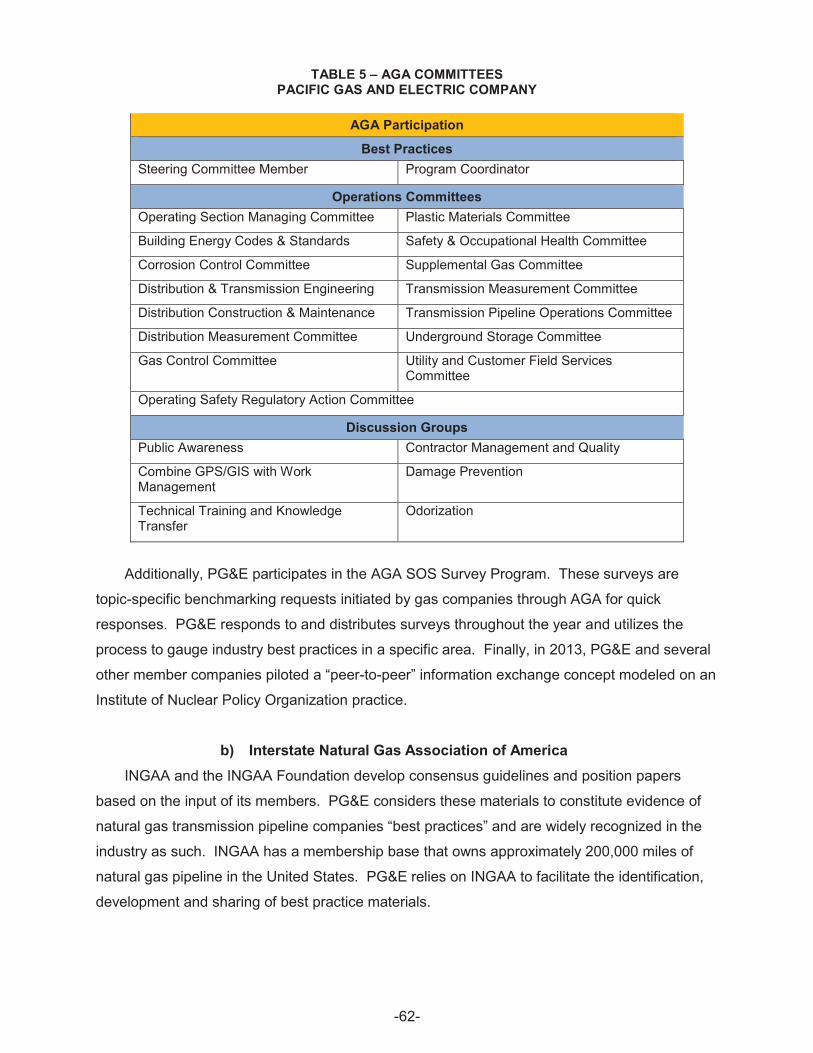
TABLE 5 – AGA COMMITTEES PACIFIC GAS AND ELECTRIC COMPANY
AGA Participation
Best Practices Steering Committee Member Program Coordinator
Operations Committees Operating Section Managing Committee Plastic Materials Committee
Building Energy Codes & Standards Safety & Occupational Health Committee
Corrosion Control Committee Supplemental Gas Committee
Distribution & Transmission Engineering Transmission Measurement Committee
Distribution Construction & Maintenance Transmission Pipeline Operations Committee
Distribution Measurement Committee Underground Storage Committee
Gas Control Committee Utility and Customer Field Services Committee
Operating Safety Regulatory Action Committee
Discussion Groups Public Awareness Contractor Management and Quality
Combine GPS/GIS with Work Management
Damage Prevention
Technical Training and Knowledge Transfer
Odorization
Additionally, PG&E participates in the AGA SOS Survey Program. These surveys are
topic-specific benchmarking requests initiated by gas companies through AGA for quick
responses. PG&E responds to and distributes surveys throughout the year and utilizes the
process to gauge industry best practices in a specific area. Finally, in 2013, PG&E and several
other member companies piloted a “peer-to-peer” information exchange concept modeled on an
Institute of Nuclear Policy Organization practice.
b) Interstate Natural Gas Association of America INGAA and the INGAA Foundation develop consensus guidelines and position papers
based on the input of its members. PG&E considers these materials to constitute evidence of
natural gas transmission pipeline companies “best practices” and are widely recognized in the
industry as such. INGAA has a membership base that owns approximately 200,000 miles of
natural gas pipeline in the United States. PG&E relies on INGAA to facilitate the identification,
development and sharing of best practice materials.
-62
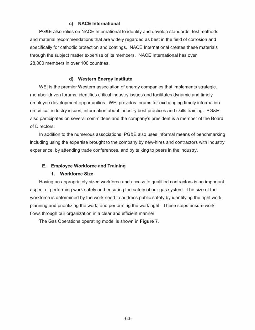
c) NACE International PG&E also relies on NACE International to identify and develop standards, test methods
and material recommendations that are widely regarded as best in the field of corrosion and
specifically for cathodic protection and coatings. NACE International creates these materials
through the subject matter expertise of its members. NACE International has over
28,000 members in over 100 countries.
d) Western Energy Institute WEI is the premier Western association of energy companies that implements strategic,
member-driven forums, identifies critical industry issues and facilitates dynamic and timely
employee development opportunities. WEI provides forums for exchanging timely information
on critical industry issues, information about industry best practices and skills training. PG&E
also participates on several committees and the company’s president is a member of the Board
of Directors.
In addition to the numerous associations, PG&E also uses informal means of benchmarking
including using the expertise brought to the company by new-hires and contractors with industry
experience, by attending trade conferences, and by talking to peers in the industry.
E. Employee Workforce and Training 1. Workforce Size
Having an appropriately sized workforce and access to qualified contractors is an important
aspect of performing work safely and ensuring the safety of our gas system. The size of the
workforce is determined by the work need to address public safety by identifying the right work,
planning and prioritizing the work, and performing the work right. These steps ensure work
flows through our organization in a clear and efficient manner.
The Gas Operations operating model is shown in Figure 7.
-63
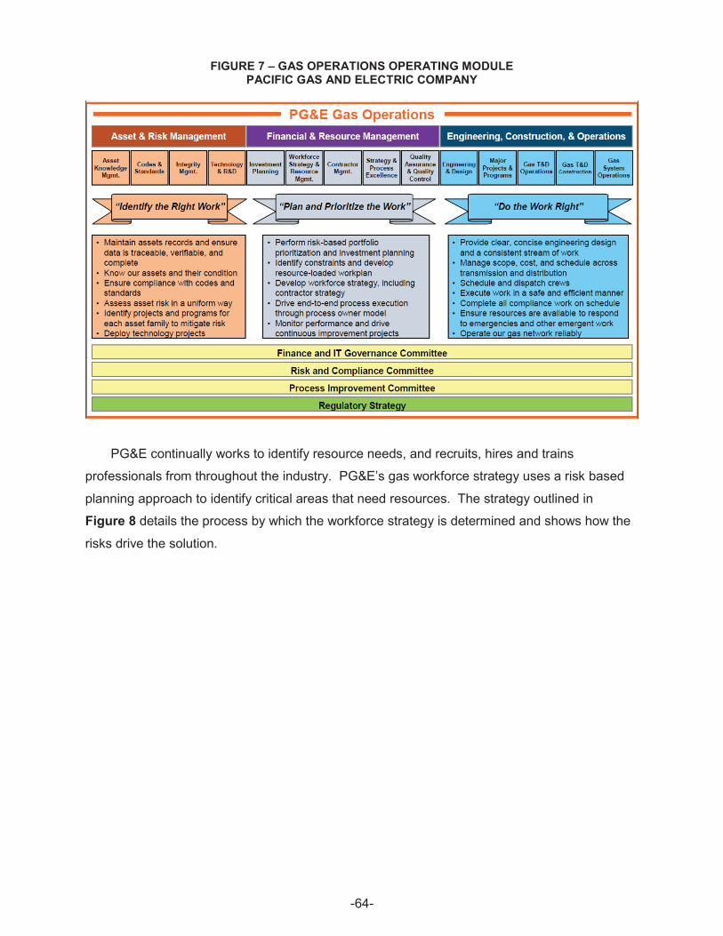
FIGURE 7 – GAS OPERATIONS OPERATING MODULE PACIFIC GAS AND ELECTRIC COMPANY
PG&E continually works to identify resource needs, and recruits, hires and trains
professionals from throughout the industry. PG&E’s gas workforce strategy uses a risk based
planning approach to identify critical areas that need resources. The strategy outlined in
Figure 8 details the process by which the workforce strategy is determined and shows how the
risks drive the solution.
-64
FIGURE 8 – WORKFORCE STRATEGY OUTLINE PACIFIC GAS AND ELECTRIC COMPANY
Through 2014, PG&E plans to hire an additional 1,400 gas employees. This increase in
Gas Operations employees supports the focus on safety and compliance through the successful
execution of operating improvements and investment plans for both gas transmission and
distribution assets.
2. Employee Training The cornerstone to ensuring PG&E’s gas facilities are designed, constructed, maintained,
operated, and retired in a safe and reliable manner is maintaining a workforce of highly skilled,
competent and experienced technical employees. Prioritization of training program
improvements is determined and driven by regulatory changes, new tools and instruments,
standards and policy changes and strengthened OQ requirements.
In early 2012, PG&E finished a comprehensive benchmark study that compared PG&E’s
gas training to others utilities. Three recommendations were made in support of employee
training and PG&E’s Gas Operations training program identified approximately 100 courses that
would be developed and/or enhanced between 2012 and 2016. The three recommendations
and their status of June 2014 are included in Table 6 below.
As of Quarter 2 2014, 59 new course publications include:
x 17 courses upgraded to improve the quality of training
x 10 courses migrated from the line of business into the training organization
to deliver
-65
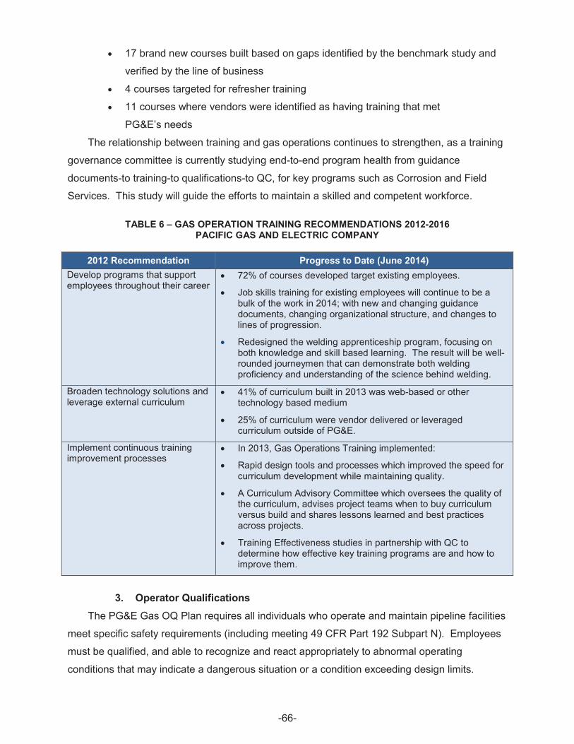
x 17 brand new courses built based on gaps identified by the benchmark study and
verified by the line of business
x 4 courses targeted for refresher training
x 11 courses where vendors were identified as having training that met
PG&E’s needs
The relationship between training and gas operations continues to strengthen, as a training
governance committee is currently studying end-to-end program health from guidance
documents-to training-to qualifications-to QC, for key programs such as Corrosion and Field
Services. This study will guide the efforts to maintain a skilled and competent workforce.
TABLE 6 – GAS OPERATION TRAINING RECOMMENDATIONS 2012-2016 PACIFIC GAS AND ELECTRIC COMPANY
2012 Recommendation Progress to Date (June 2014) Develop programs that support x 72% of courses developed target existing employees. employees throughout their career
x
x
Job skills training for existing employees will continue to be a bulk of the work in 2014; with new and changing guidance documents, changing organizational structure, and changes to lines of progression.
Redesigned the welding apprenticeship program, focusing on both knowledge and skill based learning. The result will be well-rounded journeymen that can demonstrate both welding proficiency and understanding of the science behind welding.
Broaden technology solutions and x 41% of curriculum built in 2013 was web-based or other leverage external curriculum
x
technology based medium
25% of curriculum were vendor delivered or leveraged curriculum outside of PG&E.
Implement continuous training x In 2013, Gas Operations Training implemented: improvement processes
x
x
x
Rapid design tools and processes which improved the speed for curriculum development while maintaining quality.
A Curriculum Advisory Committee which oversees the quality of the curriculum, advises project teams when to buy curriculum versus build and shares lessons learned and best practices across projects.
Training Effectiveness studies in partnership with QC to determine how effective key training programs are and how to improve them.
3. Operator Qualifications The PG&E Gas OQ Plan requires all individuals who operate and maintain pipeline facilities
meet specific safety requirements (including meeting 49 CFR Part 192 Subpart N). Employees
must be qualified, and able to recognize and react appropriately to abnormal operating
conditions that may indicate a dangerous situation or a condition exceeding design limits.
-66
PG&E’s OQ standard identifies required operating and maintenance tasks, provides
guidance for achieving compliance with the requirements of 49 CFR Part 192 Subpart N,
establishes qualification methods for performing covered tasks on a gas pipeline facility and
identifies covered tasks/subtasks.
Testing requirements include knowledge and performance evaluations. The knowledge
evaluation (written and/ or oral test) verifies that the employee understands the standards and
procedures. The performance evaluation verifies the application of the employee’s knowledge.
PG&E continuously monitors the status of employees who must be qualified, and will be
implementing improvements for tracking and reporting.
PG&E published an OQ standard that replaced the current OQ plan. The new standard,
based on the ASME best practice standard, B-31Q, includes:
x Identifying approved evaluation methods for both initial and subsequent
qualifications. PG&E moved a portion of their OQ evaluations to scripted oral
performance based. Performance based evaluations for many of our tasks provide
better insight into an employee’s Knowledge, Skills, and Abilities.
x Setting requalification intervals at 3 years, instead of 5 years. This change aligns
with industry best practices and gives the employee opportunities to validate their
technical competence.
x Clarifying that the approved Span of Control ratio for an operator qualified individual
to oversee the work of other non-qualified personnel is 1:1. This was not clear in
our original document, so clarity was provided.
x Requirements for suspending or removing an OQ. Suspending and removing OQ’s
is an integral part of our OQ program. This ability is empowered to all supervision
personnel who either believe their employees can no longer perform the task
safely, and efficiently, or the employee no longer requires the OQ. The new
standard provides better guidance based on ASME B-31Q standard, as to when to
remove or suspend an employee’s qualifications.
x Specifying the responsibilities for communicating changes in company guidance
documents that affect the OQ program. The language in the new standard was
enhanced and clarified to ensure all affected departments are aligned with the
requirements of the OQ program.
x Provisions for addressing OQ personnel acquired as part of a merger or acquisition
of another company. The provision was added to clarify the language in the
OQ plan to align with ASME B 31Q.
x Language to address the OQ expiration term for contract personnel.
-67
x Specifying that all evaluation methods are administered in English, in alignment
with industry best practices.
As part of the new standard, six new procedures were developed:
x Procedures defining OQ administration
x Procedures addressing roles and responsibilities and scheduling of OQ evaluations
x Procedures documenting the evaluation processes
x Procedure documenting the OQ suspension process and requirements
4. Contractor Safety, Training, and Oversight Much like full-time PG&E employees contractors are also a cornerstone in ensuring PG&E’s
workforce consists of highly skilled, competent, and experienced technical personnel. Prior to
starting a job, PG&E confirms that contractors, and subcontractors, are qualified to complete the
contracted work. Contractor’s Safety Programs are reviewed by internal and external
organizations to evaluate the content, qualifications, and industry metrics, including but not
limited to, OSHA Recordable Incident Rate, Total Incident Rate, Lost-Work Days, Restrictions
and Transfers and Experience Modification Rate. Contractors on major projects are also given
site specific awareness orientations or specific information about the job, which is provided in
person at the job-site and through computer based training managed by a third-party. The
computer based training covers PG&E’s safety expectations and typical hazards associated
with the work. There is also a module on Gas Safety Excellence, which is instrumental in
communicating PG&E’s expectations around quality and safety.
Once construction on a major project has started, PG&E oversees the contractor’s
performance and clearly communicates contract terms that hold contractors accountable for
safety quality. This is done through regular job-site observations and meetings with the
contractors to ensure their success. Job-site observations start during the pre-job
walk-throughs to evaluate site specific hazards prior to starting work. PG&E schedules regular
meetings with contractors to ensure expectations are met. Meetings consist of overall
performance feedback, sharing of best practices, lessons learned, communication of new
processes, and trends seen in the field. On a quarterly basis, PG&E’s leadership and contractor
leadership meet to discuss overall performance at a Company level. PG&E engages their
leadership to understand potential opportunities to improve the overall program.
At all of the meetings, contractors are provided a dashboard on metrics that they are
measured on. These metrics are communicated at the beginning of the year and managed
throughout the year to ensure their success. Metrics include, At-Fault Dig in Rate, Public
Safety, Near-hits, OSHA Recordable Injuries, Lost Work Day Cases and Preventable Motor
Vehicle Incidents. The metrics are compared against and established to match Gas Operations
-68
Safety metrics and industry standards. After the job is completed, PG&E evaluates the
contractor’s performance utilizing a scorecard developed by PG&E Sourcing department. The
scorecard includes Safety performance and other contractual obligations. The purpose of the
scorecard is to evaluate and manage contractors for future work.
5. Partnership With Local Unions Union-represented employees make up almost 70% of PG&E’s workforce, and are integral
in the Company providing safe, and reliable gas service. As such, PG&E works collaboratively
with its union partners to ensure its union-represented employees have a stable and productive
work environment, and are able to voice their concerns to improve their jobs. In 2014, PG&E
has been collaborating with union leadership on various projects such as updating the lines of
progression, Mapping Advancement Program, and PG&E’s leak survey optimization program.
The line of progression effort will update job duties, training and certification for almost
every represented field based position. The line of progression changes will help thousands of
union-represented employees have a clear vision of their career paths and the training
necessary for these new roles.
Updating the Mapping Advancement Program entails a rewrite of PG&E’s mapping training
for union-represented mapping employees. PG&E developed a team of SME’s (which were all
union-represented employees), PG&E’s Planning & Support team and Learning Academy to
support this effort and update the program. The Mapping Advancement Program will enhance
the required training program for all of our mapping technicians in order to progress to the
senior mapping technician classification. Once the program is updated, it will help maintain the
program with our changing business needs resulting in improved mapping, enhanced records,
and safer operations. We are also developing a training program for Field Engineers and Field
Engineer Technicians. This is a collaborative effort that involves union represented SME’s and
management. Once this training is complete, it will provide consistency and standardization to
training new employees.
Another important example of collaboration between PG&E and union leaders is the leak
optimization program, which incorporates advanced leak detection technology, and includes a
streamlined and bundled approach to finding and fixing leaks. The benefits of this program
include a significant reduction in leaks, improved work performance, enhanced system
reliability, and increased public safety. Further, we are partnering with our union partners
additional safety-related improvements, such as enhanced crew coverage, and the on-call
processes to further improve response time, as well as use of GPS to confirm worker location.
-69
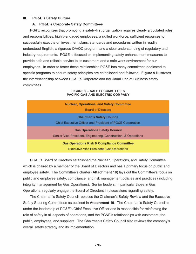
III. PG&E’s Safety Culture A. PG&E’s Corporate Safety Committees
PG&E recognizes that promoting a safety-first organization requires clearly articulated roles
and responsibilities, highly-engaged employees, a skilled workforce, sufficient resources to
successfully execute on investment plans, standards and procedures written in readily
understood English, a rigorous QA/QC program, and a clear understanding of regulatory and
industry requirements. PG&E is focused on implementing safety enhancement measures to
provide safe and reliable service to its customers and a safe work environment for our
employees. In order to foster these relationships PG&E has many committees dedicated to
specific programs to ensure safety principles are established and followed. Figure 9 illustrates
the interrelationship between PG&E’s Corporate and individual Line of Business safety
committees. FIGURE 9 – SAFETY COMMITTEES
PACIFIC GAS AND ELECTRIC COMPANY
Nuclear, Operations, and Safety Committee
Board of Directors
Chairman’s Safety Council
Chief Executive Officer and President of PG&E Corporation
Gas Operations Safety Council
Senior Vice President, Engineering, Construction, & Operations
Gas Operations Risk & Compliance Committee Executive Vice President, Gas Operations
PG&E’s Board of Directors established the Nuclear, Operations, and Safety Committee,
which is chaired by a member of the Board of Directors and has a primary focus on public and
employee safety. The Committee’s charter (Attachment 18) lays out the Committee’s focus on
public and employee safety, compliance, and risk management policies and practices (including
integrity management for Gas Operations). Senior leaders, in particular those in Gas
Operations, regularly engage the Board of Directors in discussions regarding safety.
The Chairman’s Safety Council replaces the Chairman’s Safety Review and the Executive
Safety Steering Committees as outlined in Attachment 19. The Chairman’s Safety Council is
under the leadership of PG&E’s Chief Executive Officer and is responsible for reinforcing the
role of safety in all aspects of operations, and the PG&E’s relationships with customers, the
public, employees, and suppliers. The Chairman’s Safety Council also reviews the company’s
overall safety strategy and its implementation.
-70
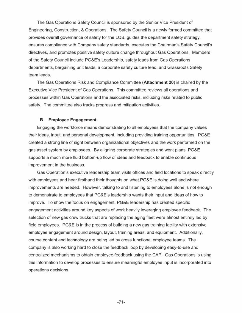
The Gas Operations Safety Council is sponsored by the Senior Vice President of
Engineering, Construction, & Operations. The Safety Council is a newly formed committee that
provides overall governance of safety for the LOB, guides the department safety strategy,
ensures compliance with Company safety standards, executes the Chairman’s Safety Council’s
directives, and promotes positive safety culture change throughout Gas Operations. Members
of the Safety Council include PG&E’s Leadership, safety leads from Gas Operations
departments, bargaining unit leads, a corporate safety culture lead, and Grassroots Safety
team leads.
The Gas Operations Risk and Compliance Committee (Attachment 20) is chaired by the
Executive Vice President of Gas Operations. This committee reviews all operations and
processes within Gas Operations and the associated risks, including risks related to public
safety. The committee also tracks progress and mitigation activities.
B. Employee Engagement Engaging the workforce means demonstrating to all employees that the company values
their ideas, input, and personal development, including providing training opportunities. PG&E
created a strong line of sight between organizational objectives and the work performed on the
gas asset system by employees. By aligning corporate strategies and work plans, PG&E
supports a much more fluid bottom-up flow of ideas and feedback to enable continuous
improvement in the business.
Gas Operation’s executive leadership team visits offices and field locations to speak directly
with employees and hear firsthand their thoughts on what PG&E is doing well and where
improvements are needed. However, talking to and listening to employees alone is not enough
to demonstrate to employees that PG&E’s leadership wants their input and ideas of how to
improve. To show the focus on engagement, PG&E leadership has created specific
engagement activities around key aspects of work heavily leveraging employee feedback. The
selection of new gas crew trucks that are replacing the aging fleet were almost entirely led by
field employees. PG&E is in the process of building a new gas training facility with extensive
employee engagement around design, layout, training areas, and equipment. Additionally,
course content and technology are being led by cross functional employee teams. The
company is also working hard to close the feedback loop by developing easy-to-use and
centralized mechanisms to obtain employee feedback using the CAP. Gas Operations is using
this information to develop processes to ensure meaningful employee input is incorporated into
operations decisions.
-71
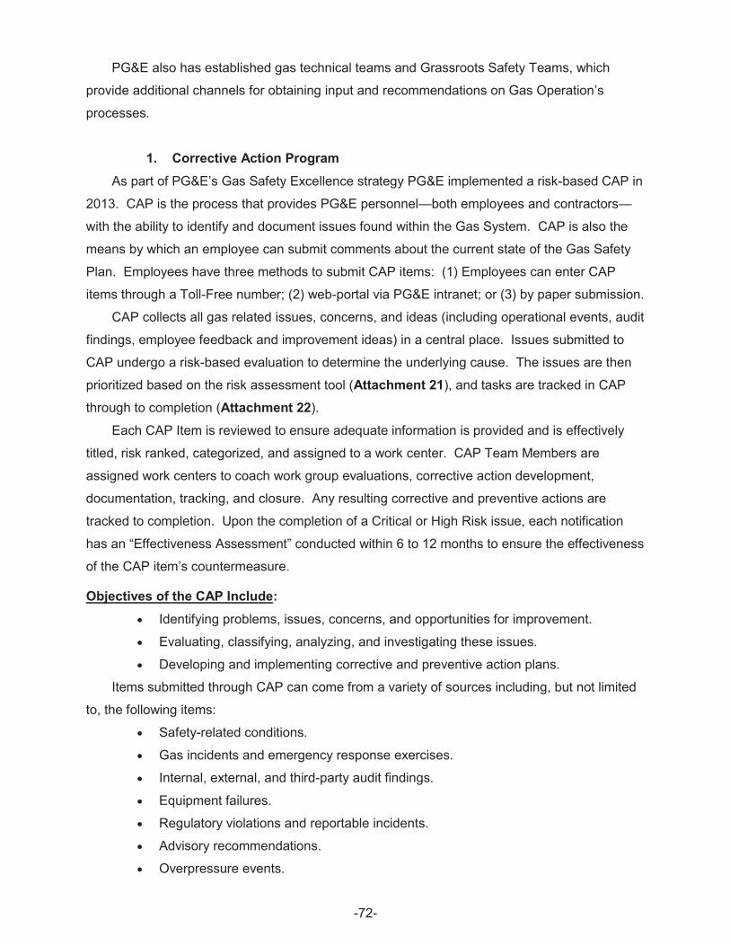
PG&E also has established gas technical teams and Grassroots Safety Teams, which
provide additional channels for obtaining input and recommendations on Gas Operation’s
processes.
1. Corrective Action Program As part of PG&E’s Gas Safety Excellence strategy PG&E implemented a risk-based CAP in
2013. CAP is the process that provides PG&E personnel—both employees and contractors—
with the ability to identify and document issues found within the Gas System. CAP is also the
means by which an employee can submit comments about the current state of the Gas Safety
Plan. Employees have three methods to submit CAP items: (1) Employees can enter CAP
items through a Toll-Free number; (2) web-portal via PG&E intranet; or (3) by paper submission.
CAP collects all gas related issues, concerns, and ideas (including operational events, audit
findings, employee feedback and improvement ideas) in a central place. Issues submitted to
CAP undergo a risk-based evaluation to determine the underlying cause. The issues are then
prioritized based on the risk assessment tool (Attachment 21), and tasks are tracked in CAP
through to completion (Attachment 22).
Each CAP Item is reviewed to ensure adequate information is provided and is effectively
titled, risk ranked, categorized, and assigned to a work center. CAP Team Members are
assigned work centers to coach work group evaluations, corrective action development,
documentation, tracking, and closure. Any resulting corrective and preventive actions are
tracked to completion. Upon the completion of a Critical or High Risk issue, each notification
has an “Effectiveness Assessment” conducted within 6 to 12 months to ensure the effectiveness
of the CAP item’s countermeasure.
Objectives of the CAP Include: x Identifying problems, issues, concerns, and opportunities for improvement.
x Evaluating, classifying, analyzing, and investigating these issues.
x Developing and implementing corrective and preventive action plans.
Items submitted through CAP can come from a variety of sources including, but not limited
to, the following items:
x Safety-related conditions.
x Gas incidents and emergency response exercises.
x Internal, external, and third-party audit findings.
x Equipment failures.
x Regulatory violations and reportable incidents.
x Advisory recommendations.
x Overpressure events.
-72
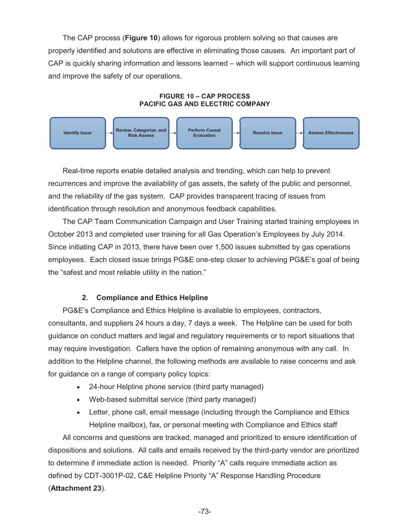
The CAP process (Figure 10) allows for rigorous problem solving so that causes are
properly identified and solutions are effective in eliminating those causes. An important part of
CAP is quickly sharing information and lessons learned – which will support continuous learning
and improve the safety of our operations.
FIGURE 10 – CAP PROCESS PACIFIC GAS AND ELECTRIC COMPANY
Identify Issue Perform Causal Evaluation Resolve Issue Assess EffectivenessReview, Categorize, and
Risk Assess
Real-time reports enable detailed analysis and trending, which can help to prevent
recurrences and improve the availability of gas assets, the safety of the public and personnel,
and the reliability of the gas system. CAP provides transparent tracing of issues from
identification through resolution and anonymous feedback capabilities.
The CAP Team Communication Campaign and User Training started training employees in
October 2013 and completed user training for all Gas Operation’s Employees by July 2014.
Since initiating CAP in 2013, there have been over 1,500 issues submitted by gas operations
employees. Each closed issue brings PG&E one-step closer to achieving PG&E’s goal of being
the “safest and most reliable utility in the nation.”
2. Compliance and Ethics Helpline PG&E’s Compliance and Ethics Helpline is available to employees, contractors,
consultants, and suppliers 24 hours a day, 7 days a week. The Helpline can be used for both
guidance on conduct matters and legal and regulatory requirements or to report situations that
may require investigation. Callers have the option of remaining anonymous with any call. In
addition to the Helpline channel, the following methods are available to raise concerns and ask
for guidance on a range of company policy topics:
x 24-hour Helpline phone service (third party managed)
x Web-based submittal service (third party managed)
x Letter, phone call, email message (including through the Compliance and Ethics
Helpline mailbox), fax, or personal meeting with Compliance and Ethics staff
All concerns and questions are tracked, managed and prioritized to ensure identification of
dispositions and solutions. All calls and emails received by the third-party vendor are prioritized
to determine if immediate action is needed. Priority “A” calls require immediate action as
defined by CDT-3001P-02, C&E Helpline Priority “A” Response Handling Procedure
(Attachment 23).
-73
3. Material Problem Reporting In addition to the Helpline and CAP, PG&E maintains a material problem reporting (MPR)
system that allows employees to report problems with any materials, tools, gas/electric/other
equipment or infrastructure, and vehicles. Each MPR is logged in the appropriate database and
reviewed by a subject matter expert to identify improvements. The Material Problem Reporting
allows trends to be identified in a timely manner so that actions can be taken with emerging
material problems. The system is used by field employees and receiving inspection personnel.
Each write up is fully reviewed and responded to by an engineer. The submitter of the MPR and
the writer receives feedback from that engineer in written form.
4. Grassroots Safety Teams The grassroots safety philosophy hinges on management and union-represented
employees sharing responsibility for safe practices and implementation of corrective actions.
Leadership is the key to safety performance, and safety leadership comes from all levels of an
organization. This team is an employee-led effort that promotes safe work habits, shares
information and best practices, promotes open and honest communications, and finds
innovative methods to perform work safely. Grassroots members, at all levels, have direct
influence on the development and implementation of initiatives developed by the
Senior Leadership.
The companywide Grassroots Safety Team structure allows for the sharing of grassroots
based ideas across all LOB in order to identify best practices and improve safety performance.
Each LOB is committed to supporting and maintaining a functioning Grassroots Team to gather
ideas and feedback from employees on safety issues. Grassroots team members discuss
issues and solutions with all LOB representatives as well as senior leadership for PG&E. The
lead from the Grassroots safety team serves as a liaison to the LOB Safety Council to ensure
alignment across all safety teams.
5. Near Hits Reporting A Near Hit is defined as an unplanned event that did not result in harm or injury to
employees, contractors or the public, but could have done so. PG&E encourages employees to
share unsafe occurrences and hazardous situations beyond their own work groups, yards and
offices, so we can learn from one another, take action and prevent the incidents from happening
again. Examples of a Near Hit include potential damage to equipment or property, disruption of
service, or personal safety/hazard conditions such as driving.
Near Hit sharing, used in a preventive, non-punitive manner, is an effective way to reduce
employee, contractor and public safety incidents and injuries. This approach also creates a
-74
safety climate where employees look out for one another and prevent incidents from occurring
to co-workers, contractors and the public. All employees are encouraged to submit near hits
and can do so via the PG&E intranet site, mail, phone, fax, or by contacting one of PG&E’s
grassroots safety teams or their Union. Gas Operations uses the CAP to report near hits and
those items are then reported up to the corporate Near Hit program to consolidate lists.
By sharing near hits openly, we can learn from one another and take the actions necessary
to prevent future incidents and injuries. PG&E is committed to improving the safety of our
employees, contractors and our communities.
IV. Process Safety Process Safety is the prevention and mitigation of unintentional loss of containment
(i.e., releases of potentially dangerous materials or energy) through the use of robust processes
and good equipment reliability. It is a blend of engineering and management skills used in a
systematic and structured approach to identify, understand, and mitigate hazards and risks,
which could impact the public, employees, environment, and asset. Process Safety prevents
catastrophic accidents. The goal of Process Safety is to develop effective processes and
ensure employees fully understand the implications of what they are doing. Process Safety
provides value to external and internal stakeholders including the public, customers, regulators,
and employees in a variety of other industries.
Process Safety requires engaging stakeholders so they can understand the of
vulnerabilities of our everyday work and commit to Process Safety, understand hazards and
risk, manage risk and learn from experience to ensure the safety of gas assets and operations.
The fundamental benefit of Process Safety is a safer business. To promote Process Safety,
PG&E developed a Process Safety Management System, which includes engineering and
administrative controls to protect employees, the public, the environment and/or the assets and
reduce the chance of low probability/high consequence incidents.
To stimulate Process Safety Management excellence and continuous improvement, PG&E
implemented a Risk-Based Process Safety (RBPS) framework developed by AIChEs’ CCPS.
The RBPS management system approach recognizes that all hazards and risks are not
equal; consequently, it advocates that more resources should be focused on more significant
hazards and higher risks. The RBPS management system approach is built on four
foundational blocks, which are further divided into a total of 20 elements (see Figure 11). As
part of the deployment of the RBPS management system approach, PG&E performed Process
Safety benchmarking and gap analysis for all the Process Safety elements.
-75
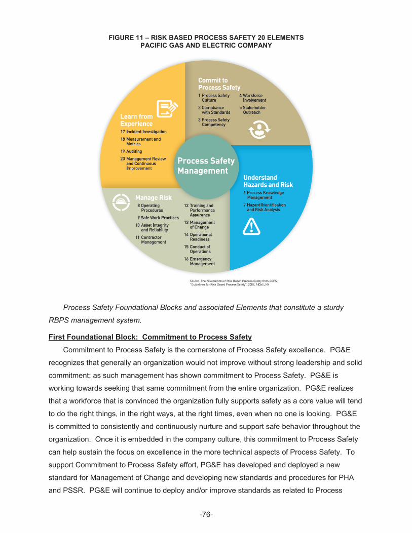
FIGURE 11 – RISK BASED PROCESS SAFETY 20 ELEMENTS PACIFIC GAS AND ELECTRIC COMPANY
Process Safety Foundational Blocks and associated Elements that constitute a sturdy
RBPS management system.
First Foundational Block: Commitment to Process Safety Commitment to Process Safety is the cornerstone of Process Safety excellence. PG&E
recognizes that generally an organization would not improve without strong leadership and solid
commitment; as such management has shown commitment to Process Safety. PG&E is
working towards seeking that same commitment from the entire organization. PG&E realizes
that a workforce that is convinced the organization fully supports safety as a core value will tend
to do the right things, in the right ways, at the right times, even when no one is looking. PG&E
is committed to consistently and continuously nurture and support safe behavior throughout the
organization. Once it is embedded in the company culture, this commitment to Process Safety
can help sustain the focus on excellence in the more technical aspects of Process Safety. To
support Commitment to Process Safety effort, PG&E has developed and deployed a new
standard for Management of Change and developing new standards and procedures for PHA
and PSSR. PG&E will continue to deploy and/or improve standards as related to Process
-76
Safety in order to: (1) operate and maintain safe gas operation assets; (2) consistently
implement Process Safety practices; and (3) minimize legal liability.
As part of Commitment to Process Safety, PG&E performed a formal external
benchmarking and gap analysis for critical to success elements of Process Safety, including
Process Safety Culture and Compliance to Standards. In addition, to promote improvement,
closure of the gaps, and the drive towards maturity, PG&E developed Process Safety roadmaps
for each of the elements part of the Commitment to Process Safety foundation block. The first
five elements are:
1. Process Safety Culture51
2. Compliance to Standards52
3. Process Safety Competency
4. Workforce Involvement
5. Stakeholder Outreach
Second Foundational Block: Understand Hazards and Risk
PG&E recognizes that organizations that understand hazards and risk are better able to
allocate limited resources in the most effective manner. As such, PG&E has deployed HIRA
and PHA in order to evaluate risks within the gas operation activities and assets. Both HIRA
and PHA are used to identify hazards and evaluate risk of assets, throughout their life cycle, to
make certain that risks to employees, the public, the environment and/or the assets are
consistently controlled within a set risk tolerance. The HIRA and PHA typically address five risk
questions to a level of detail commensurate with analysis objectives, life cycle stage, available
information, and resources. Based upon the level of understanding of these answers, PG&E
can decide what actions, if any, are needed to eliminate, reduce, or control existing risk. The
five risk questions are:
x What can go wrong?
x How bad can it be?
x How often might it happen?
x Are the proper safeguards in place?
x How can I better manage risk?
Key activities where PG&E evaluates for risks include facility design and modification,
operational procedures, workforce competence, human factors, emergency arrangements,
51 Critical to success Process Safety element for which a formal benchmarking study was performed.
52 Critical to success Process Safety element for which a formal benchmarking study was performed.
-77

protective devices, instrumentation and alarms, inspection and maintenance, permit to work,
asset records and data quality, and third-party activities.
As part of Understanding Hazards and Risk, PG&E performed a formal external
benchmarking and gap analysis for critical to success elements of Process Safety, including
Hazard Identification & Risk Analysis. In addition, to promote improvement, closure of the
gaps and the drive towards maturity, PG&E developed Process Safety roadmaps for each of
the elements part of the Understanding Hazards and Risk foundation block. The next
two elements are:
6. Process Knowledge Management
7. Hazard Identification & Risk Analysis53
PG&E commits to using hazard and risk information to plan, develop, and deploy stable,
lower-risk operations in order to promote long term success and a safer business.
Third Foundational Block: Manage Risk PG&E Manages Risks by focusing on three issues:
x Prudently operating and maintaining processes that pose the risk;
x Managing changes to those processes to ensure that the risk remains tolerable;
and
x Preparing for, responding to, and managing incidents that do occur.
As such, PG&E has deployed the PSSR which helps ensure that risks have been identified
and addressed; that there is agreement on all startup requirements including training, drawings,
spare parts and operating procedures before starting new equipment and facilities; and that
there are alternatives to address problems.
As part of Managing Risk, PG&E performed a formal external benchmarking and gap
analysis for critical to success elements of Process Safety, including Asset Integrity and
Reliability and MOC. In addition, to promote improvement, closure of the gaps and the drive
towards maturity, PG&E developed Process Safety roadmaps for each of the elements part of
the Managing Risk foundation block. Elements 8 through 16 are:
8. Operating Procedures
9. Safe Work Practices
10. Asset Integrity & Reliability54
11. Contractor Management
12. Training & Performance Assurance
53 Critical to success Process Safety element for which a formal benchmarking study was performed.
54 Critical to success Process Safety element for which a formal benchmarking study was performed.
-78
13. Management of Change55
14. Operational Readiness/Pre-Startup Safety Review
15. Conduct of Operations
16. Emergency Management
PG&E recognizes that managing risk helps the company deploy management systems that
help sustain long-term, incident-free, and profitable operations.
Fourth Foundational Block: Learn From Experience Learning from Experience involves monitoring and acting on internal and external sources
of information. Despite PG&E’s best efforts, operations do not always proceed as planned, so
PG&E is turning its mistakes – and those of others – into opportunities to improve Process
Safety efforts. The ways to learn from experience that PG&E promotes are to: (1) apply best
practices to make the most effective use of available resources; (2) correct deficiencies exposed
by internal incidents and near hits; and (3) apply lessons learned from other organizations.
To support Learning from Experience effort, PG&E is reviewing and revising the current
incident investigation process into an integral end-to-end process for Gas Operations in order to
comply with regulatory requirements, include a Process Safety perspective and provide effective
governance with stakeholders’ role, responsibilities and accountability.
In addition to recognizing opportunities to better manage risk, PG&E’s PSM system
promotes for a Process Safety culture and infrastructure to help employees remember the
lessons and apply them in the future. PG&E is developing the following metrics to provide
timely feedback on the workings of RBPS management systems:
x Total Count of Process Safety Incidents
x Process Safety Total Incident Rate
x Near Hits Process Safety Events
x Mechanical Integrity
x Management of Change
x Action Items Follow-Up
PG&E recognizes that management review, a periodic honest self-evaluation, helps sustain
existing performance and drive improvement in areas deemed important by management.
As part of Learning from Experience, PG&E performed a formal external benchmarking and
gap analysis for critical to success elements of Process Safety, including Measurement and
Metrics. In addition, to promote improvement, closure of the gaps and the drive towards
55 Critical to success Process Safety element for which a formal benchmarking study was performed.
-79
maturity, PG&E developed Process Safety roadmaps for each of the elements part of the
Learning from Experience foundation block. The remaining four elements are:
17. Incident Investigation
18. Measurement & Metrics56
19. Auditing
20. Management Review & Continuous Improvement
V. Conclusion The 2014 Gas Safety Plan Update demonstrates how PG&E implements processes and
procedures to achieve its commitment to becoming the safest and most reliable, natural gas
company in the nation. The Gas Safety Excellence framework guides how PG&E operates,
conducts, and manages all parts of its business by putting safety and people at the heart of
everything it does; investing in the reliability and integrity of its gas system; and, by continuously
improving the effectiveness and affordability of its processes. In addition, PG&E continuously
invests in its facilities, employees, technology, and operations to enhance the long-term safety,
reliability and affordability of its system.
56 Critical to success Process Safety element for which a formal benchmarking study was performed.
-80
-82

APPENDIX B (Appendix B consists of one (1) archival grade CD. The contents of the CD include
Attachments 1 through 23 to Pacific Gas and Electric Company’s 2014 Gas Safety Plan
Update and Compliance Statement. The CD has been provided to the Commission’s
Docket Office for filing.)