p6000a/p5000 programmable counter/timer manual · p6000a/p5000 programmable counter/timer...
TRANSCRIPT
P6000A/P5000
Programmable Counter/Timer
Operator’s Manual
NEWPORT Electronics,Inc.

CountersFrequency Meters
PID ControllersClock/Timers
PrintersProcess Meters
On/OffControllersRecordersRelativeHumidity
TransmittersThermocouples
ThermistorsWire
Rate MetersTimers
TotalizersStrain Gauge
MetersVoltmetersMultimeters
Soldering IronTesterspH pens
pH ControllerspH Electrodes
RTDsThermowellsFlow Sensors
For Immediate AssistanceIn the U.S.A. and Canada: 1-800-NEWPORT®
In Mexico: (95) 800-NEWPORTSM
Or call your local NEWPORT Office.
It is the policy of NEWPORT to comply with all worldwide safety and EMC/EMI regulations that apply. NEWPORT is constantly pursuingcertification of its products to the European New Approach Directives. NEWPORT will add the CE mark to every appropriate device uponcertification.
The information contained in this document is believed to be correct but NEWPORT Electronics, Inc. accepts no liability for any errors itcontains, and reserves the right to alter specifications without notice.
WARNING: These products are not designed for use in, and should not be used for, patient connected applications.
TRADEMARK NOTICE: a®, , , newportUS.com, , , and the “MeterCase Bezel Design” are trademarks of NEWPORT Electronics, Inc.
PATENT NOTICE: This product is covered by one or more of the following patents: U.S. Pat. No. Des. 336,895; 5,274,577 / Canada 2052599;2052600 / Italy 1249456; 1250938 / France Brevet No. 91 12756 / Spain 2039150; 2048066 / UK Patent No. GB2 249 837; GB2 248 954 /Germany DE 41 34398 C2. Other US and International Patents Pending.
NEWPORT®NEWPORT®
Internet [email protected]
Additional products from
NEWPORTnetSM On-Line Servicehttp://www.newportUS.com
This device is marked with the international caution symbol. It is important to read the Setup Guide before installing or commissioningthis device as it contains important information relating to safety and EMC.
NEWPORT Electronics,Inc.
i
PART ONE QUICK-START GUIDE
TABLE OF CONTENTS PAGE
1.0 GENERAL INFORMATION ................................................................................................1-1
2.0 GETTING STARTED ..........................................................................................................1-2
2.1 Safety Considerations ..............................................................................................1-22.2 Assembly & Mounting “Classic” ..............................................................................1-32.3 Assembly & Mounting “Designer” ............................................................................1-6
3.0 POWER AND SIGNAL CONNECTIONS ..........................................................................1-10
3.1 Turning It On ..........................................................................................................1-103.2 Testing....................................................................................................................1-10
4.0 EASY PROGRAMMING WITH DISPLAY PROMPTS ....................................................1-11
4.1 Features ................................................................................................................1-114.2 Display Symbols and Descriptions ........................................................................1-144.3 Programming Pushbuttons ....................................................................................1-154.4 Factory-Default Settings ........................................................................................1-164.5 Programming and Application Examples ..............................................................1-16
APPENDICES
APPENDIX A MODIFICATIONS - JUMPER DIAGRAMS................................................1-25
A.1 Lockout Features............................................................................................1-25A.2 Frequency Response ....................................................................................1-26
APPENDIX B CONTROL INPUTS/OUTPUTS ................................................................1-27
Free software for NEWPORT devices featuring Ethernet or Serial Communicationsis on the CD-ROM enclosed with this shipment.
To download the latest software release (or request a free CD-ROM) please go to:www.newportUS.com/software
ii
ILLUSTRATIONS PAGE
Figure 2-1 Exploded View “Classic” ........................................................................................1-3
Figure 2-2 Case Dimensions, Front View “Classic” ................................................................1-5
Figure 2-3 Exploded View “Designer” ....................................................................................1-6
Figure 2-4 Case Dimensions, Front View “Designer”..............................................................1-8
Figure 2-5 Rear Views ............................................................................................................1-9
Figure 3-1 Rear Panel Pin Assignments ..............................................................................1-10
Figure A-1 Display Board Jumper Locations ........................................................................1-25
Figure A-2 Main Board Jumper Locations ............................................................................1-26
Table B-1 Output Effect Immediately After RESET..............................................................1-27
iii
PART TWO REFERENCE
TABLE OF CONTENTS PAGE
5.0 PROGRAMMING ................................................................................................................2-1
5.1 General Information ................................................................................................2-15.2 Selecting the Function to be Performed ..................................................................2-25.3 Multiply or Divide by a Scale Factor ........................................................................2-25.4 Selecting an Offset ..................................................................................................2-35.5 Choosing Auto-Range or Fixed Display Decimal-Point Location ............................2-35.6 Selecting Rising or Falling Edge Triggers for A and B Inputs..................................2-35.7 Setting Lower and Upper Alarm (or Control) Values................................................2-55.8 Selecting a Gate Time..............................................................................................2-65.9 Configuration #1 and #2 ..........................................................................................2-65.10 Calibration of the Crystal Frequency ......................................................................2-65.11 Replacing the Stored Program with the Active Program ........................................2-7
6.0 REMOTE PROGRAMMING................................................................................................2-7
6.1 General Information ................................................................................................2-76.2 ASCII Output ............................................................................................................2-86.3 Setup Data ..............................................................................................................2-96.4 ASCII Input ............................................................................................................2-126.5 Interfacing Examples..............................................................................................2-136.6 Programming Considerations ................................................................................2-146.7 Parity Checking ......................................................................................................2-186.8 Timing ....................................................................................................................2-186.9 Modem Operation ..................................................................................................2-186.10 0 - 20 mA, ASCII Output ........................................................................................2-18
7.0 TROUBLESHOOTING CHART ........................................................................................2-20
iv
PAGE
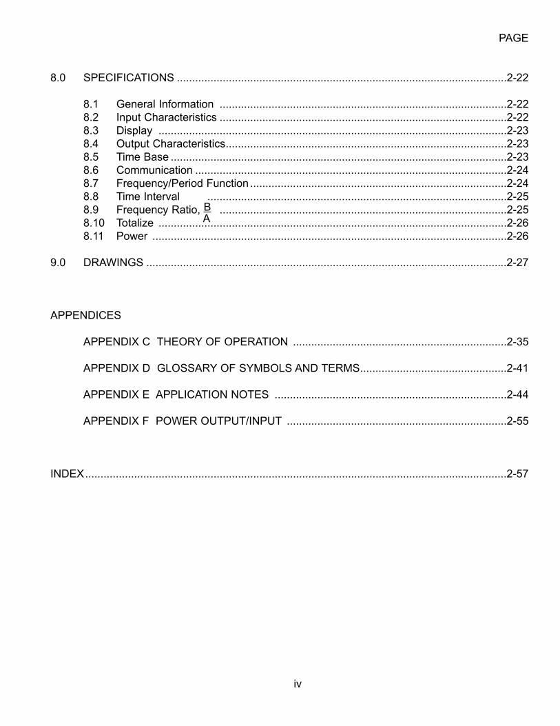
8.0 SPECIFICATIONS ............................................................................................................2-22
8.1 General Information ..............................................................................................2-228.2 Input Characteristics ..............................................................................................2-228.3 Display ..................................................................................................................2-238.4 Output Characteristics............................................................................................2-238.5 Time Base ..............................................................................................................2-238.6 Communication ......................................................................................................2-248.7 Frequency/Period Function ....................................................................................2-248.8 Time Interval ..................................................................................................2-258.9 Frequency Ratio, B ..............................................................................................2-258.10 Totalize ..................................................................................................................2-268.11 Power ....................................................................................................................2-26
9.0 DRAWINGS ......................................................................................................................2-27
APPENDICES
APPENDIX C THEORY OF OPERATION ......................................................................2-35
APPENDIX D GLOSSARY OF SYMBOLS AND TERMS................................................2-41
APPENDIX E APPLICATION NOTES ............................................................................2-44
APPENDIX F POWER OUTPUT/INPUT ........................................................................2-55
INDEX..........................................................................................................................................2-57
A
v
ILLUSTRATIONS PAGE
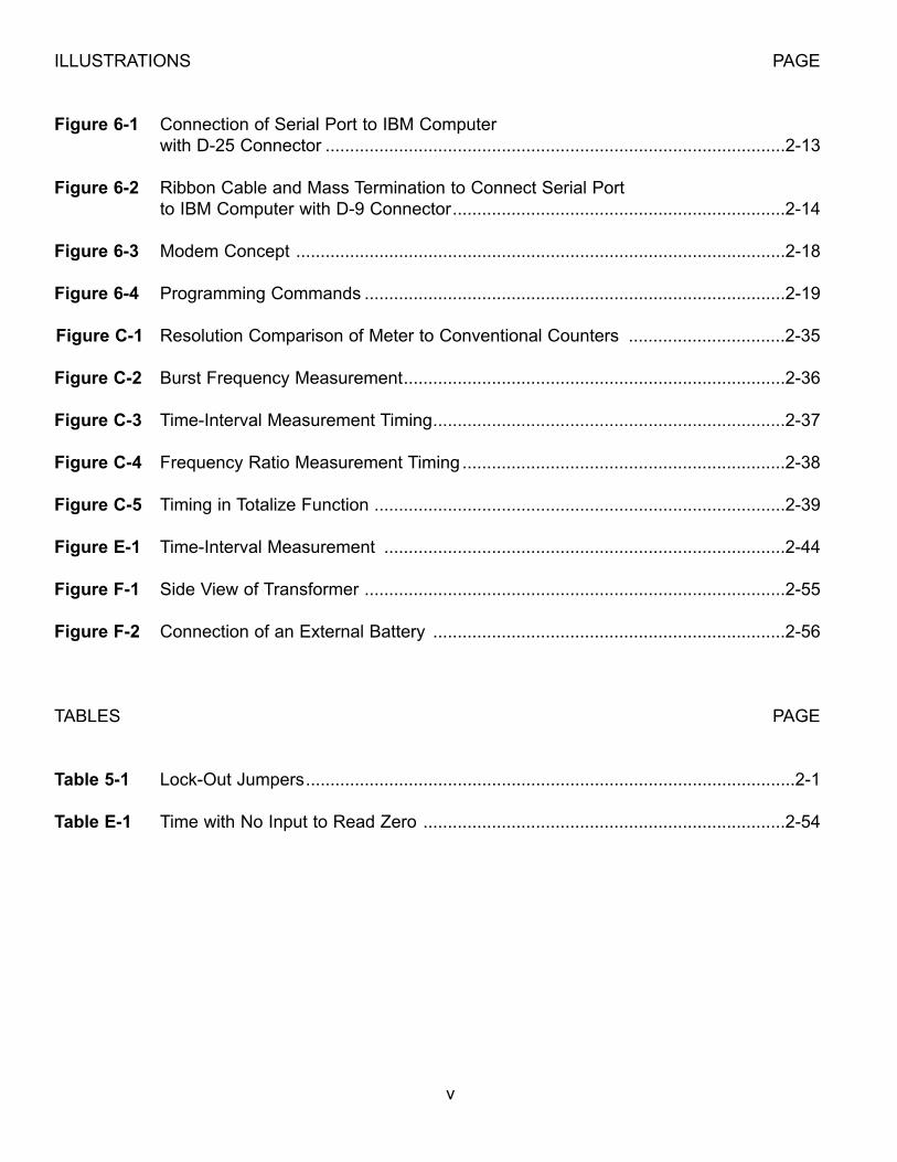
Figure 6-1 Connection of Serial Port to IBM Computerwith D-25 Connector ..............................................................................................2-13
Figure 6-2 Ribbon Cable and Mass Termination to Connect Serial Port to IBM Computer with D-9 Connector....................................................................2-14
Figure 6-3 Modem Concept ....................................................................................................2-18
Figure 6-4 Programming Commands ......................................................................................2-19
Figure C-1 Resolution Comparison of Meter to Conventional Counters ................................2-35
Figure C-2 Burst Frequency Measurement..............................................................................2-36
Figure C-3 Time-Interval Measurement Timing........................................................................2-37
Figure C-4 Frequency Ratio Measurement Timing ..................................................................2-38
Figure C-5 Timing in Totalize Function ....................................................................................2-39
Figure E-1 Time-Interval Measurement ..................................................................................2-44
Figure F-1 Side View of Transformer ......................................................................................2-55
Figure F-2 Connection of an External Battery ........................................................................2-56
TABLES PAGE
Table 5-1 Lock-Out Jumpers....................................................................................................2-1
Table E-1 Time with No Input to Read Zero ..........................................................................2-54

vi
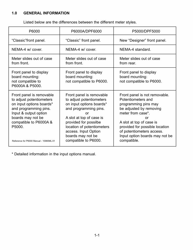
1.0 GENERAL INFORMATION
Listed below are the differences between the different meter styles.
P6000 P6000A/DPF6000 P5000/DPF5000
“Classic”front panel. “Classic” front panel. New “Designer” front panel.
NEMA-4 w/ cover. NEMA-4 w/ cover. NEMA-4 standard.
Meter slides out of case Meter slides out of case Meter slides out of casefrom front. from front. from rear.
Front panel to display Front panel to display Front panel to displayboard mounting: board mounting: board mounting:not compatible to not compatible to P6000. not compatible to P6000.P6000A & P5000.
Front panel is removable Front panel is removable Front panel is not removable.to adjust potentiometers to adjust potentiometers Potentiometers andon input options boards* on input options boards* programming pins mayand programming pins. and programming pins. be adjusted by removingInput & output option or meter from case*.boards may not be A slot at top of case is orcompatible to P6000A & provided for possilbe A slot at top of case is P5000. location of potentiometers provided for possible location
access. Input Option of potentiometers access. boards may not be Input option boards may not be
Reference for P6000 Manual - 10980ML-01 compatible to P6000. compatible.
* Detailed information in the input options manual.
1-1
1-2
This meter is a fully programmable counter with six-digit resolution for totalizinginput pulses or for measuring frequency, period, time interval and frequency ratio.
The meter is menu-driven for simple programming. Alphanumeric prompts on thedisplay make it easy to program with front panel pushbuttons. Pushing the appropriate|button scrolls the display through the functions and settings, repeating (for corrections) asoften as desired. Alternatively, a personal computer can be used to program the meterand to monitor the display data via the RS-232 port (standard feature). If desired, theprogram setup may be stored in nonvolatile memory for recall upon demand or at power-on.
The two setpoints and corresponding alarm outputs make it an ON-OFF Controller foreither stand-alone or computer-controlled applications. The crystal time base may beelectronically calibrated, either manually from the front panel or remotely with a personalcomputer.
2.0 GETTING STARTED
2.1 SAFETY CONSIDERATIONS
This instrument is protected according to Class II of IEC 348 and VDE 0411. To ensuresafe operation, follow the guidelines below:
POWER VOLTAGE - Verify that the instrument is connected for the power voltage rating that willbe used.
POWER WIRING - This instrument has no power-on switch; it will be in operation as soon asthe power is connected.
RAIN OR MOISTURE - Do not expose the instrument to condensing moisture.
FUMES AND GASES - Do not operate the instrument in the presence of flammable gases orfumes.
EXERCISE CAUTION - As with any electronic instrument, high voltages may be exposed whenattempting to install, calibrate, or remove parts of the meter.
1-3
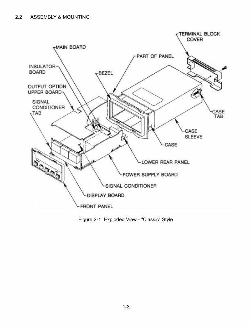
2.2 ASSEMBLY & MOUNTING
Figure 2-1 Exploded View - “Classic” Style

1-4
The “Classic” meter is housed in a 4896-150, 1/8 DIN case. The electronic circuitry can beinstalled or removed from the front and is attached to the case with two #8 screws throughthe rear panel.
To install a pre-configured meter:
NOTE: Installation of input options (mezzanine board) and output options (upper board)is shown in the Input Options and the Output Options Manuals.
1. Use a Phillips-head screwdriver to remove the three screws on the rear of the case
2. Slide the sleeve off the case (see Figure 2-1 Exploded View).
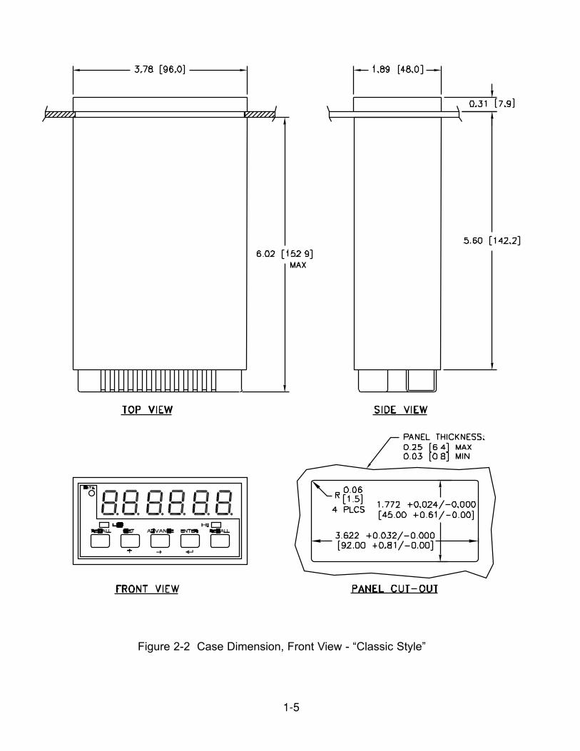
3. Verify the panel cutout dimensions in Figure 2-2 Case Dimensions. Insert the case in thepane cutout from the front and slide the sleeve on from the rear. Install the two #8 screwsto secure the sleeve to the case.
4. Connect all connectors and attach the terminal block cover with the #4 screw.
1-5
Figure 2-2 Case Dimension, Front View - “Classic Style”
1-6
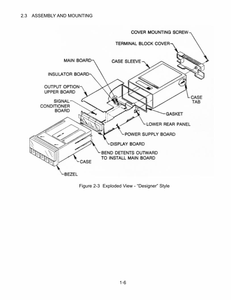
2.3 ASSEMBLY AND MOUNTING
Figure 2-3 Exploded View - “Designer” Style
1-7
The “Designer” meter circuit boards are housed in a 4896 1/8-DIN plastic case and sleeve. The bezel, display lens and pushbuttons are NEMA-4 (waterproof) sealed to the case; theelectronics assembly slides into the case from the rear when the flexible side panel detentsare moved aside. Six front pins on the electronics assembly then mate with the connectorson the inside of the case.
To install a preconfigured meter:
NOTE: The main board, display board and power supply board are soldered together as a basic unit. Installation of input options (mezzazine board) and output options(upper board) is shown in the Input Options and the Output Options Manuals.
1. Use a phillips-head screwdriver to remove the three screws on the rear of the case.
2. Slide the case sleeve off the case.
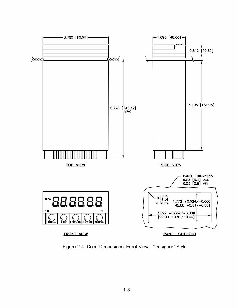
3. Verify the panel cutout dimensions in Figure 2-4 Case Dimensions. For panel mounting,the entire edge of the panel cutout is sandwiched between the bezel (and gasket) in frontand the sleeve in the rear. Install the two #8 screws to secure the sleeve to the case.
4. Connect all connectors and attach the terminal block cover with the #4 screw.
1-8
Figure 2-4 Case Dimensions, Front View - “Designer” Style
1-9
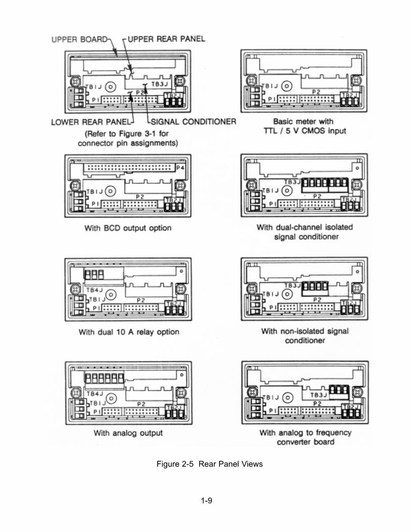
Figure 2-5 Rear Panel Views
1-10
3.0 POWER AND SIGNAL CONNECTIONS
3.1 TURNING IT ON
INCORRECT POWER INPUT CAN DAMAGE YOUR P6000A/P5000 COUNTER
Connect the proper voltage to the power screw terminal (TB1). The meter will display theprogrammed function (default is FrEq) until it reads the input signal. Then that value willbe shown.
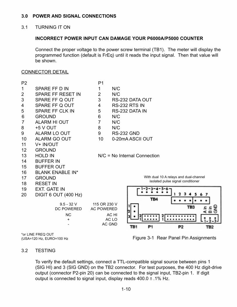
CONNECTOR DETAIL
P2 P11 SPARE FF D IN 1 N/C2 SPARE FF RESET IN 2 N/C3 SPARE FF Q OUT 3 RS-232 DATA OUT4 SPARE FF Q OUT 4 RS-232 RTS IN5 SPARE FF CLK IN 5 RS-232 DATA IN6 GROUND 6 N/C7 ALARM HI OUT 7 N/C8 +5 V OUT 8 N/C9 ALARM LO OUT 9 RS-232 GND10 ALARM GO OUT 10 0-20mA ASCII OUT11 V+ IN/OUT12 GROUND13 HOLD IN N/C = No Internal Connection14 BUFFER IN15 BUFFER OUT16 BLANK ENABLE IN*17 GROUND18 RESET IN19 EXT. GATE IN20 DIGIT 6 OUT (400 Hz)
3.2 TESTING
To verify the default settings, connect a TTL-compatible signal source between pins 1 (SIG HI) and 3 (SIG GND) on the TB2 connector. For test purposes, the 400 Hz digit-driveoutput (connector P2-pin 20) can be connected to the signal input, TB2-pin 1. If digitoutput is connected to signal input, display reads 400.0 + .1% Hz.
Figure 3-1 Rear Panel Pin Assignments*or LINE FREQ OUT(USA=120 Hz, EURO=100 Hz
With dual 10 A relays and dual-channelisolated pulse signal conditioner
9.5 - 32 V 115 OR 230 VDC POWERED AC POWERED
NC AC HI+ AC LO- AC GND
1-11
4.0 EASY PROGRAMMING WITH DISPLAY PROMPTS
Section 4 explains the front-panel programmable features (in bold), their display character,and how to modify the existing setup.
4.1 FEATURES
Frequency Measures the input frequency. Displays in Hz (Scale Factor = 1); can alsodisplay in kHz, RPM (for tachometer application), feet/sec, or other engineeringunits.
Period Measures the input period (inverse of frequency) and displays in millisecondscan also display in seconds, minutes, or other engineering units.
Time Interval Use for pulse width measurement, or for stopwatch applications where resetafter each measurement is desired. Measures the time interval (or averagetime interval) between the rising or falling edges of two signals. Displays inmilliseconds (Scale Factor = 1); can also display in seconds, minutes, or otherengineering units.
Frequency Used as an FB/FA frequency ratio meter with FB and FA up to 7 MHz. Ideal forRatio b/A monitoring the relative speed of shafts, conveyor belts and other moving
machinery.
Totalize Use for cumulative totals, stopwatch applications, as an up-counting (positivescale factor) or down-counting (negative scale factor) totalizer.
Scale factor The input may be multiplied or divided by any desired scale factor from -9.9.9.9.9. to +9.9.9.9.9.9. with a decimal point selected in any position shown.
Offset After measuring the input(s), the meter multiplies or divides the result bythe scale factor and then adds the offset. The offset value can range from -
99999to 999999 *. Like SCALE, the decimal point is programmable.
Range The decimal point can be selected on any of the six positions F.F.F.F.F.F. or itcan (Display be floating (Auto-range). It should be noted that when a fixeddecimal point is Decimal selected, the meter maintains a meaningful unit ofmeasurement in the Point) reading. For example, if input frequency is 10 Hz,function equals frequency, and fixed decimal point equals 3, the display reads10.00, not .10.
* The offset is limited to +390000 in units manufactured prior to January 1988 if the scale factois positive.
1-12
Slope Determines which edge of the input pulse begins the measurement.Frequency, Period and Totalize measure A Input; Time Interval andFrequency Ratio measure both A and B Inputs.
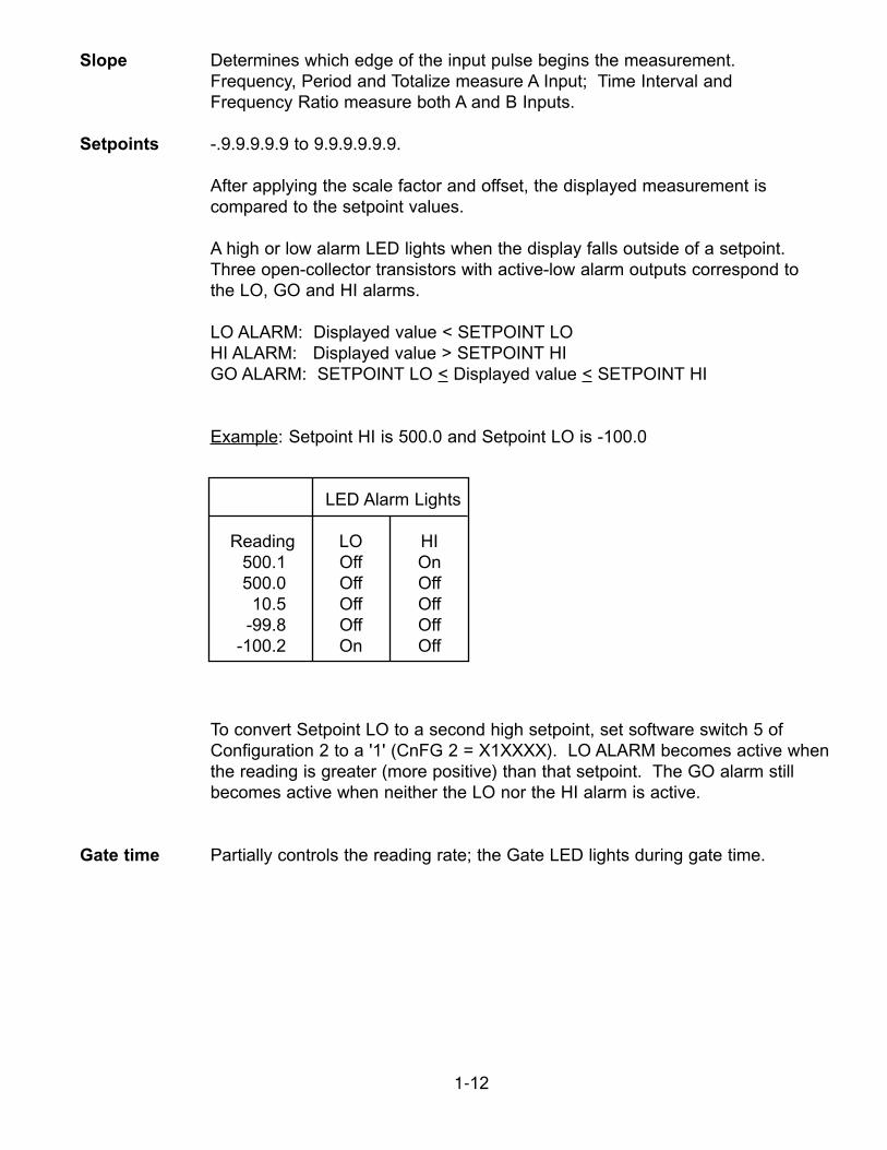
Setpoints -.9.9.9.9.9 to 9.9.9.9.9.9.
After applying the scale factor and offset, the displayed measurement iscompared to the setpoint values.
A high or low alarm LED lights when the display falls outside of a setpoint.Three open-collector transistors with active-low alarm outputs correspond tothe LO, GO and HI alarms.
LO ALARM: Displayed value < SETPOINT LOHI ALARM: Displayed value > SETPOINT HIGO ALARM: SETPOINT LO < Displayed value < SETPOINT HI
Example: Setpoint HI is 500.0 and Setpoint LO is -100.0
LED Alarm Lights
Reading LO HI500.1 Off On500.0 Off Off
10.5 Off Off-99.8 Off Off
-100.2 On Off
To convert Setpoint LO to a second high setpoint, set software switch 5 ofConfiguration 2 to a '1' (CnFG 2 = X1XXXX). LO ALARM becomes active when the reading is greater (more positive) than that setpoint. The GO alarm stillbecomes active when neither the LO nor the HI alarm is active.
Gate time Partially controls the reading rate; the Gate LED lights during gate time.
1-13
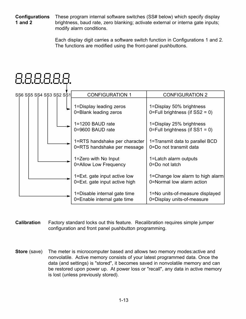
Configurations These program internal software switches (SS# below) which specify display1 and 2 brightness, baud rate, zero blanking; activate external or interna gate inputs;
modify alarm conditions.
Each display digit carries a software switch function in Configurations 1 and 2.The functions are modified using the front-panel pushbuttons.
8.8.8.8.8.8.SS6 SS5 SS4 SS3 SS2 SS1 CONFIGURATION 1 CONFIGURATION 2
1=Display leading zeros 1=Display 50% brightness0=Blank leading zeros 0=Full brightness (if SS2 = 0)
1=1200 BAUD rate 1=Display 25% brightness0=9600 BAUD rate 0=Full brightness (if SS1 = 0)
1=RTS handshake per character 1=Transmit data to parallel BCD0=RTS handshake per message 0=Do not transmit data
1=Zero with No Input 1=Latch alarm outputs0=Allow Low Frequency 0=Do not latch
1=Ext. gate input active low 1=Change low alarm to high alarm0=Ext. gate input active high 0=Normal low alarm action
1=Disable internal gate time 1=No units-of-measure displayed 0=Enable internal gate time 0=Display units-of-measure
Calibration Factory standard locks out this feature. Recalibration requires simple jumperconfiguration and front panel pushbutton programming.
Store (save) The meter is microcomputer based and allows two memory modes:active andnonvolatile. Active memory consists of your latest programmed data. Once thedata (and settings) is "stored", it becomes saved in nonvolatile memory and canbe restored upon power up. At power loss or "recall", any data in active memoryis lost (unless previously stored).
1-14
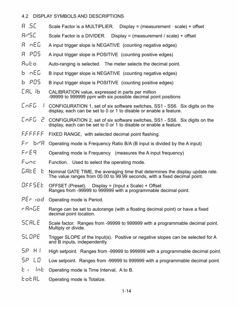
4.2 DISPLAY SYMBOLS AND DESCRIPTIONS
A .SC Scale Factor is a MULTIPLIER. Display = (measurement . scale) + offset
A/SC Scale Factor is a DIVIDER. Display = (measurement / scale) + offset
A nEG A input trigger slope is NEGATIVE (counting negative edges)
A POS A input trigger slope is POSITIVE (counting positive edges)
AuTo Auto-ranging is selected. The meter selects the decimal point.
b nEG B input trigger slope is NEGATIVE (counting negative edges)
b POS B input trigger slope is POSITIVE (counting positive edges)
CALIb CALIBRATION value, expressed in parts per million-99999 to 999999 ppm with six possible decimal point positions
CnFG 1 CONFIGURATION 1, set of six software switches, SS1 - SS6. Six digits on the display, each can be set to 0 or 1 to disable or enable a feature.
CnFG 2 CONFIGURATION 2, set of six software switches, SS1 - SS6. Six digits on the display, each can be set to 0 or 1 to disable or enable a feature.
F.FFFFF FIXED RANGE, with selected decimal point flashing.
Fr b/A Operating mode is Frequency Ratio B/A (B input is divided by the A input)
FrE9 Operating mode is Frequency (measures the A input frequency)
Func Function. Used to select the operating mode.
GAtE t Nominal GATE TIME, the averaging time that determines the display update rate. The value ranges from 00.00 to 99.99 seconds, with a fixed decimal point.
OFFSEt OFFSET (Preset). Display = (Input x Scale) + OffsetRanges from -99999 to 999999 with a programmable decimal point.
PEriod Operating mode is Period.
rAnGE Range can be set to autorange (with a floating decimal point) or have a fixed decimal point location.
SCALE Scale factor. Ranges from -99999 to 999999 with a programmable decimal point.Multiply or divide.
SLOPE Trigger SLOPE of the Input(s). Positive or negative slopes can be selected for Aand B inputs, independently.
SP HI High setpoint. Ranges from -99999 to 999999 with a programmable decimal point.
SP LO Low setpoint. Ranges from -99999 to 999999 with a programmable decimal point.
ti Int Operating mode is Time Interval, A to B.
totAL Operating mode is Totalize.
1-15
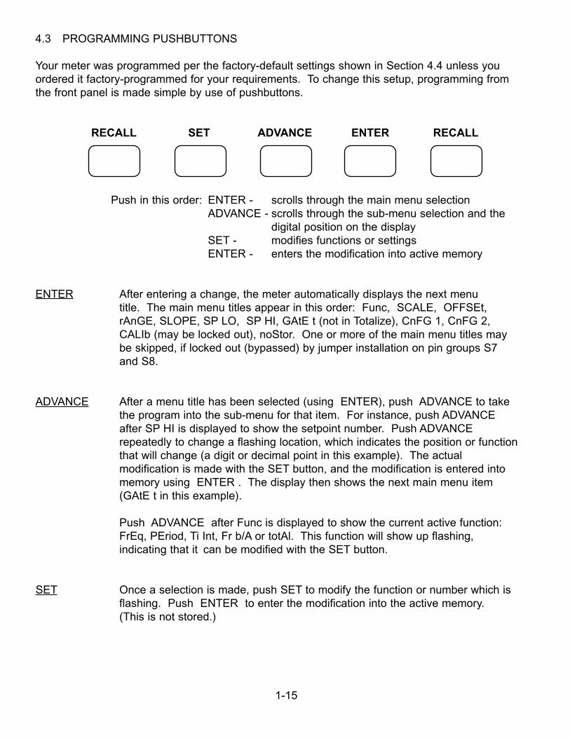
4.3 PROGRAMMING PUSHBUTTONS
Your meter was programmed per the factory-default settings shown in Section 4.4 unless youordered it factory-programmed for your requirements. To change this setup, programming fromthe front panel is made simple by use of pushbuttons.
RECALL SET ADVANCE ENTER RECALL
Push in this order: ENTER - scrolls through the main menu selectionADVANCE - scrolls through the sub-menu selection and the
digital position on the displaySET - modifies functions or settingsENTER - enters the modification into active memory
ENTER After entering a change, the meter automatically displays the next menutitle. The main menu titles appear in this order: Func, SCALE, OFFSEt,rAnGE, SLOPE, SP LO, SP HI, GAtE t (not in Totalize), CnFG 1, CnFG 2,CALIb (may be locked out), noStor. One or more of the main menu titles maybe skipped, if locked out (bypassed) by jumper installation on pin groups S7and S8.
ADVANCE After a menu title has been selected (using ENTER), push ADVANCE to takethe program into the sub-menu for that item. For instance, push ADVANCEafter SP HI is displayed to show the setpoint number. Push ADVANCErepeatedly to change a flashing location, which indicates the position or functionthat will change (a digit or decimal point in this example). The actualmodification is made with the SET button, and the modification is entered intomemory using ENTER . The display then shows the next main menu item(GAtE t in this example).
Push ADVANCE after Func is displayed to show the current active function:FrEq, PEriod, Ti Int, Fr b/A or totAl. This function will show up flashing,indicating that it can be modified with the SET button.
SET Once a selection is made, push SET to modify the function or number which isflashing. Push ENTER to enter the modification into the active memory. (This is not stored.)
1-16
RECALL Pushed simultaneously, the two RECALL buttons reset the meter. The lastprogram stored (saved) is read into active memory and will be displayed. As ina power loss, data not stored is lost.
Push SET ADVANCE ENTER simultaneously to reset the counter and start ameasurement using the latest settings (in active memory).
4.4 FACTORY-DEFAULT SETTINGS
Programmable Features
Operating Mode (Function) FrequencySetpoints Hi = 100000. Lo = 0.00000Scale Multiply by 1.00000Offset 000000.Range Fixed decimal point, FFFFFF.Trigger slope A and B PositiveNominal gate time 0.3 second (00.30)Configuration 1 000000Configuration 2 000001Calibration as appropriate
(lock-out jumper installed)
Jumpers Installed
Display board: S7-B, S8-A Locks out calibration feature
Main board: SA-M, SB-M DC-100 kHz frequency response; -20 to +25 volts maximum input
4.5 PROGRAMMING AND APPLICATION EXAMPLES
The pushbuttons scroll through the menu items repeatedly, making corrections or changessimple. If a setting is correct, just press ENTER.
1-17
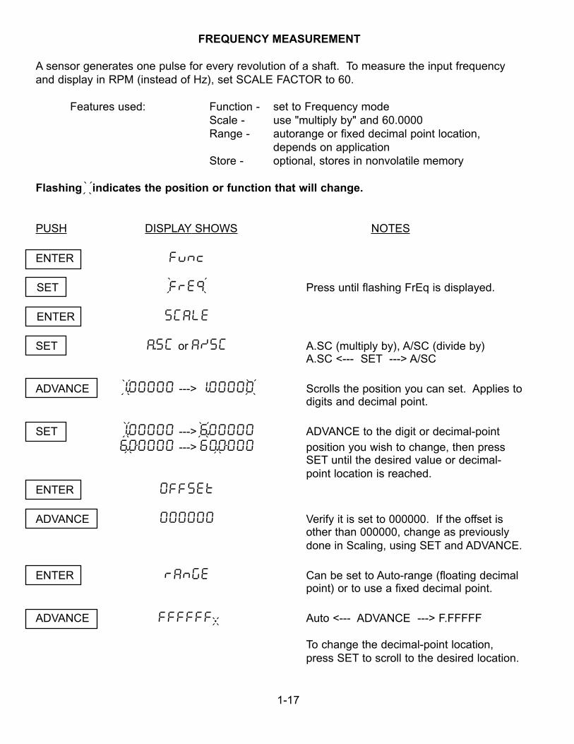
FREQUENCY MEASUREMENT
A sensor generates one pulse for every revolution of a shaft. To measure the input frequencyand display in RPM (instead of Hz), set SCALE FACTOR to 60.
Features used: Function - set to Frequency modeScale - use "multiply by" and 60.0000Range - autorange or fixed decimal point location,
depends on applicationStore - optional, stores in nonvolatile memory
Flashing indicates the position or function that will change.
PUSH DISPLAY SHOWS NOTES
ENTER FuNc
SET FrE9 Press until flashing FrEq is displayed.
ENTER SCALE
SET A.SC or A/SC A.SC (multiply by), A/SC (divide by) A.SC <--- SET ---> A/SC
ADVANCE 1.00000 ---> 1.00000 Scrolls the position you can set. Applies todigits and decimal point.
SET 1.00000 ---> 6.00000 ADVANCE to the digit or decimal-point6.00000 ---> 60.0000 position you wish to change, then press
SET until the desired value or decimal- point location is reached.
ENTER OFFSEt
ADVANCE 000000 Verify it is set to 000000. If the offset isother than 000000, change as previouslydone in Scaling, using SET and ADVANCE.
ENTER rAnGE Can be set to Auto-range (floating decimalpoint) or to use a fixed decimal point.
ADVANCE FFFFFF. Auto <--- ADVANCE ---> F.FFFFF
To change the decimal-point location,press SET to scroll to the desired location.
` ```
` `
``
` ```
` ```
`
``
` ```
` ```
` ```
`
``
1-18
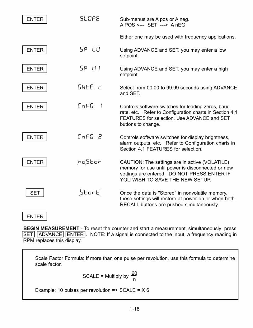
ENTER SLOPE Sub-menus are A pos or A neg.A POS <--- SET ---> A nEG
Either one may be used with frequency applications.
ENTER SP LO Using ADVANCE and SET, you may enter a lowsetpoint.
ENTER SP HI Using ADVANCE and SET, you may enter a highsetpoint.
ENTER GatE t Select from 00.00 to 99.99 seconds using ADVANCEand SET.
ENTER CnFG 1 Controls software switches for leading zeros, baudrate, etc. Refer to Configuration charts in Section 4.1FEATURES for selection. Use ADVANCE and SETbuttons to change.
ENTER CnFG 2 Controls software switches for display brightness,alarm outputs, etc. Refer to Configuration charts inSection 4.1 FEATURES for selection.
ENTER noStor CAUTION: The settings are in active (VOLATILE)memory for use until power is disconnected or newsettings are entered. DO NOT PRESS ENTER IF YOU WISH TO SAVE THE NEW SETUP.
SET StorE Once the data is "Stored" in nonvolatile memory, these settings will restore at power-on or when bothRECALL buttons are pushed simultaneously.
ENTER
BEGIN MEASUREMENT - To reset the counter and start a measurement, simultaneously pressSET ADVANCE ENTER . NOTE: If a signal is connected to the input, a frequency reading inRPM replaces this display.
Scale Factor Formula: If more than one pulse per revolution, use this formula to determinescale factor.
SCALE = Multiply by 60
Example: 10 pulses per revolution => SCALE = X 6
n
` ```
` ```
1-19
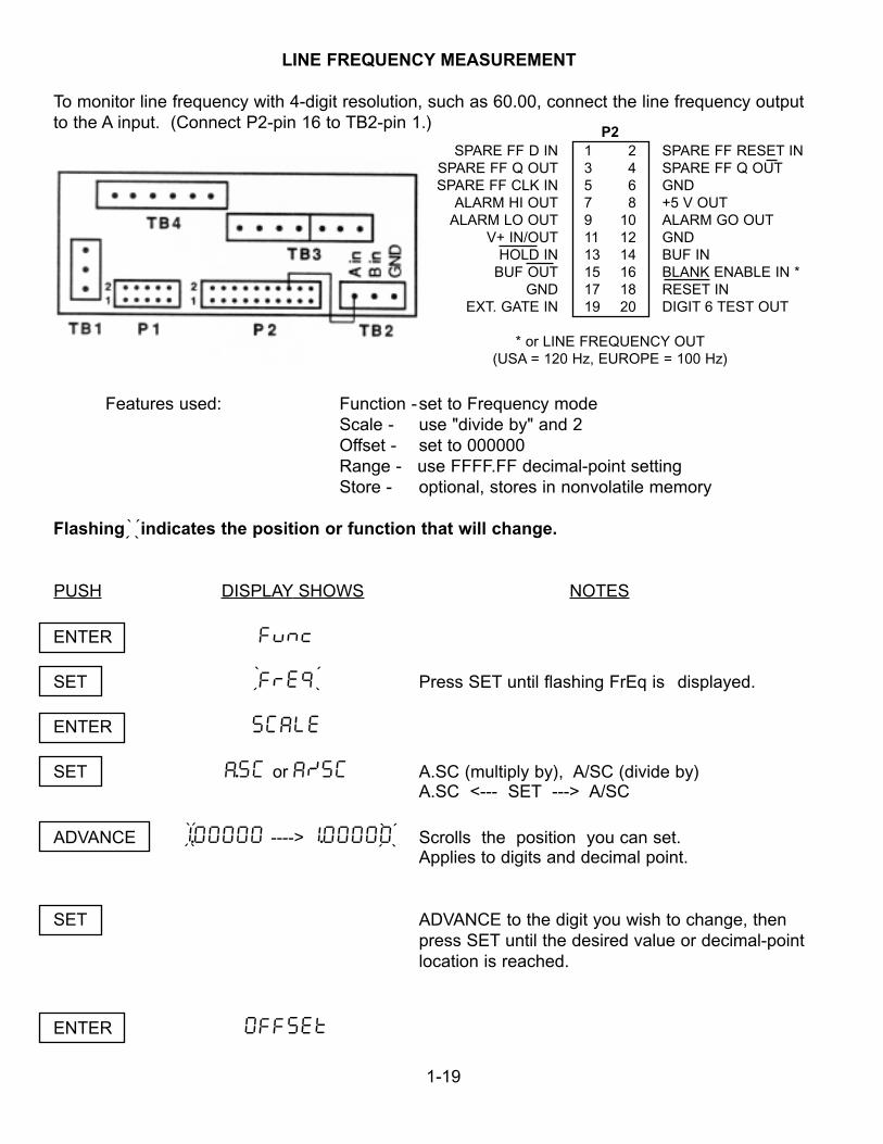
LINE FREQUENCY MEASUREMENT
To monitor line frequency with 4-digit resolution, such as 60.00, connect the line frequency outputto the A input. (Connect P2-pin 16 to TB2-pin 1.)
Features used: Function -set to Frequency modeScale - use "divide by" and 2Offset - set to 000000Range - use FFFF.FF decimal-point settingStore - optional, stores in nonvolatile memory
Flashing indicates the position or function that will change.
PUSH DISPLAY SHOWS NOTES
ENTER FuNc
SET FrE9 Press SET until flashing FrEq is displayed.
ENTER SCALE
SET A.SC or A/SC A.SC (multiply by), A/SC (divide by) A.SC <--- SET ---> A/SC
ADVANCE 1.00000 ----> 1.00000 Scrolls the position you can set.Applies to digits and decimal point.
SET ADVANCE to the digit you wish to change, thenpress SET until the desired value or decimal-pointlocation is reached.
ENTER OFFSEt
` ```
P2SPARE FF D IN 1 2 SPARE FF RESET IN
SPARE FF Q OUT 3 4 SPARE FF Q OUTSPARE FF CLK IN 5 6 GND
ALARM HI OUT 7 8 +5 V OUTALARM LO OUT 9 10 ALARM GO OUT
V+ IN/OUT 11 12 GNDHOLD IN 13 14 BUF IN
BUF OUT 15 16 BLANK ENABLE IN *GND 17 18 RESET IN
EXT. GATE IN 19 20 DIGIT 6 TEST OUT
* or LINE FREQUENCY OUT(USA = 120 Hz, EUROPE = 100 Hz)
` ```
` ```` ```
1-20
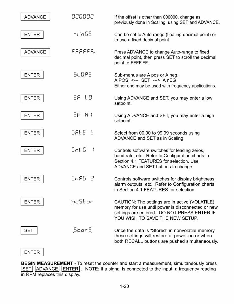
ADVANCE 000000 If the offset is other than 000000, change aspreviously done in Scaling, using SET and ADVANCE.
ENTER rAnGE Can be set to Auto-range (floating decimal point) orto use a fixed decimal point.
ADVANCE FFFFFF. Press ADVANCE to change Auto-range to fixeddecimal point, then press SET to scroll the decimalpoint to FFFF.FF.
ENTER SLOPE Sub-menus are A pos or A neg.A POS <--- SET ---> A nEGEither one may be used with frequency applications.
ENTER SP LO Using ADVANCE and SET, you may enter a lowsetpoint.
ENTER SP HI Using ADVANCE and SET, you may enter a highsetpoint.
ENTER GatE t Select from 00.00 to 99.99 seconds using ADVANCE and SET as in Scaling.
ENTER CnFG 1 Controls software switches for leading zeros, baud rate, etc. Refer to Configuration charts in Section 4.1 FEATURES for selection. Use ADVANCE and SET buttons to change.
ENTER CnFG 2 Controls software switches for display brightness,alarm outputs, etc. Refer to Configuration chartsin Section 4.1 FEATURES for selection.
ENTER noStor CAUTION: The settings are in active (VOLATILE)memory for use until power is disconnected or newsettings are entered. DO NOT PRESS ENTER IFYOU WISH TO SAVE THE NEW SETUP.
SET StorE Once the data is "Stored" in nonvolatile memory,these settings will restore at power-on or when both RECALL buttons are pushed simultaneously.
ENTER
BEGIN MEASUREMENT - To reset the counter and start a measurement, simultaneously pressSET ADVANCE ENTER . NOTE: If a signal is connected to the input, a frequency reading
in RPM replaces this display.
` ```
` ```
` `
``
1-21
TOTALIZE
To use the meter as a totalizer permanently, the function should be set to totAL and hischange should be stored in nonvolatile memory to restore at power-on. For down counting,use a negative scale factor and a positive offset. In case of power failure, the meter blanksthe display and stores the latest reading in nonvolatile memory.
Example: Use Totalize to count parts per container. Six parts per one container would be as follows.
Features used: Function - set to Totalize modeScale - use "divide by" and scale factor of "6"Store - optional, saves setup in nonvolatile memory
Flashing indicates the position or function that will change.
PUSH DISPLAY SHOWS NOTES
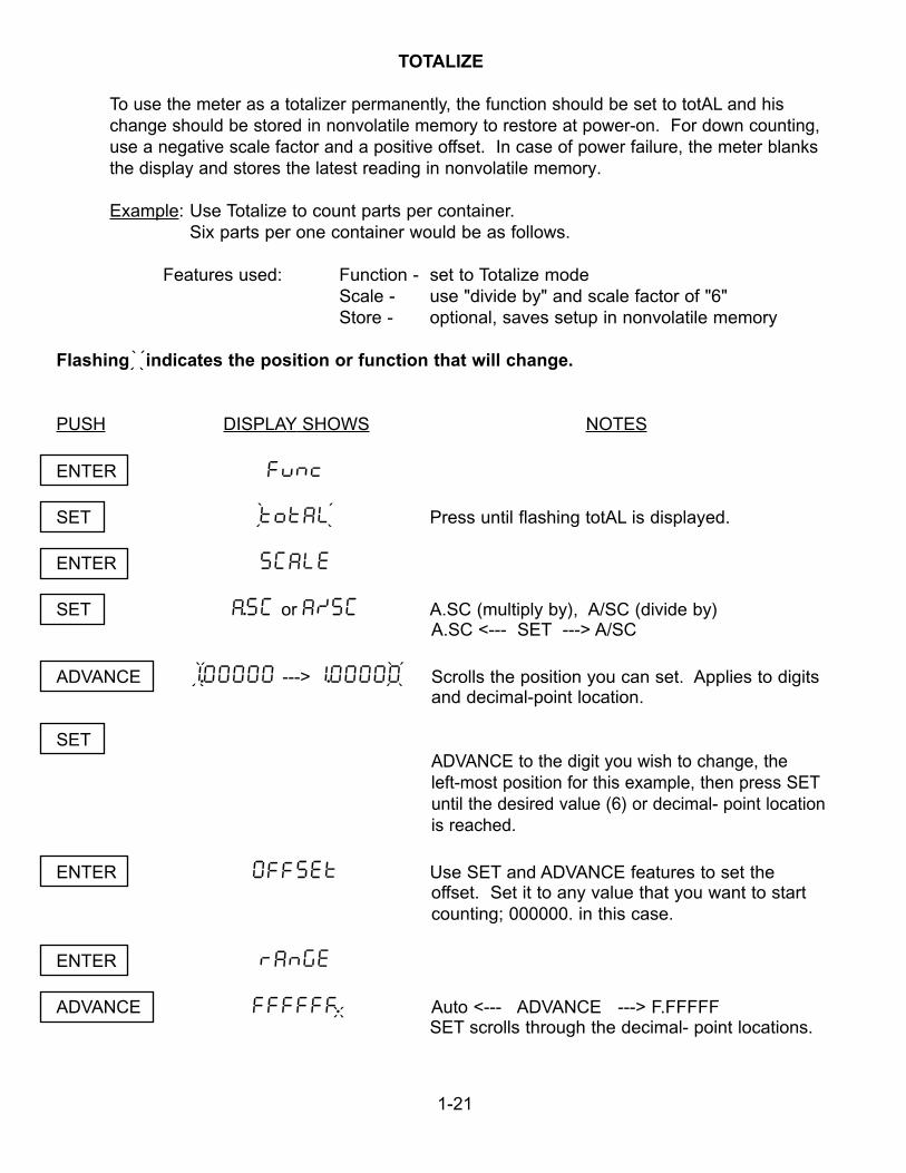
ENTER Func
SET totAL Press until flashing totAL is displayed.
ENTER SCALE
SET A.SC or A/SC A.SC (multiply by), A/SC (divide by) A.SC <--- SET ---> A/SC
ADVANCE 1.00000 ---> 1.00000 Scrolls the position you can set. Applies to digitsand decimal-point location.
SETADVANCE to the digit you wish to change, the left-most position for this example, then press SETuntil the desired value (6) or decimal- point location is reached.
ENTER OFFSEt Use SET and ADVANCE features to set theoffset. Set it to any value that you want to startcounting; 000000. in this case.
ENTER rAnGE
ADVANCE FFFFFF. Auto <--- ADVANCE ---> F.FFFFFSET scrolls through the decimal- point locations.
` ```
` `
``
` ``` ` ```
` ```
1-22
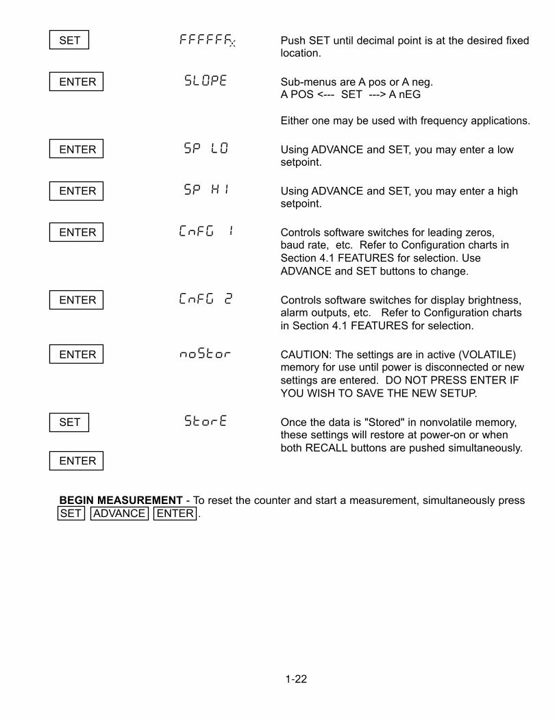
SET FFFFFF. Push SET until decimal point is at the desired fixedlocation.
ENTER SLOPE Sub-menus are A pos or A neg. A POS <--- SET ---> A nEG
Either one may be used with frequency applications.
ENTER SP LO Using ADVANCE and SET, you may enter a lowsetpoint.
ENTER SP HI Using ADVANCE and SET, you may enter a highsetpoint.
ENTER CnFG 1 Controls software switches for leading zeros, baud rate, etc. Refer to Configuration charts in Section 4.1 FEATURES for selection. Use ADVANCE and SET buttons to change.
ENTER CnFG 2 Controls software switches for display brightness,alarm outputs, etc. Refer to Configuration chartsin Section 4.1 FEATURES for selection.
ENTER noStor CAUTION: The settings are in active (VOLATILE)memory for use until power is disconnected or newsettings are entered. DO NOT PRESS ENTER IFYOU WISH TO SAVE THE NEW SETUP.
SET StorE Once the data is "Stored" in nonvolatile memory,these settings will restore at power-on or when both RECALL buttons are pushed simultaneously.
ENTER
BEGIN MEASUREMENT - To reset the counter and start a measurement, simultaneously press SET ADVANCE ENTER .
` `
``
1-23
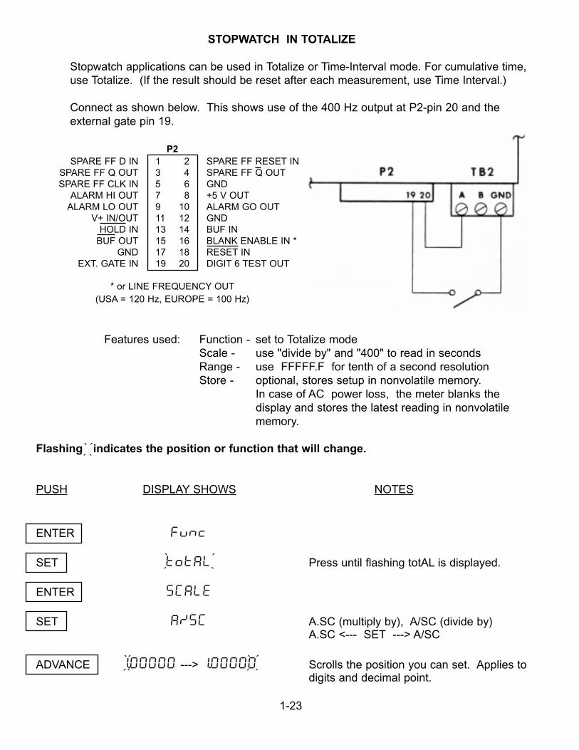
STOPWATCH IN TOTALIZE
Stopwatch applications can be used in Totalize or Time-Interval mode. For cumulative time,use Totalize. (If the result should be reset after each measurement, use Time Interval.)
Connect as shown below. This shows use of the 400 Hz output at P2-pin 20 and the external gate pin 19.
P2SPARE FF D IN 1 2 SPARE FF RESET IN
SPARE FF Q OUT 3 4 SPARE FF Q OUTSPARE FF CLK IN 5 6 GND
ALARM HI OUT 7 8 +5 V OUTALARM LO OUT 9 10 ALARM GO OUT
V+ IN/OUT 11 12 GNDHOLD IN 13 14 BUF IN
BUF OUT 15 16 BLANK ENABLE IN *GND 17 18 RESET IN
EXT. GATE IN 19 20 DIGIT 6 TEST OUT
* or LINE FREQUENCY OUT(USA = 120 Hz, EUROPE = 100 Hz)
Features used: Function - set to Totalize modeScale - use "divide by" and "400" to read in secondsRange - use FFFFF.F for tenth of a second resolutionStore - optional, stores setup in nonvolatile memory.
In case of AC power loss, the meter blanks the display and stores the latest reading in nonvolatilememory.
Flashing indicates the position or function that will change.
PUSH DISPLAY SHOWS NOTES
ENTER Func
SET totAL Press until flashing totAL is displayed.
ENTER SCALE
SET A/SC A.SC (multiply by), A/SC (divide by) A.SC <--- SET ---> A/SC
ADVANCE 1.00000 ---> 1.00000 Scrolls the position you can set. Applies todigits and decimal point.
` ```
` ```
` ```` ```
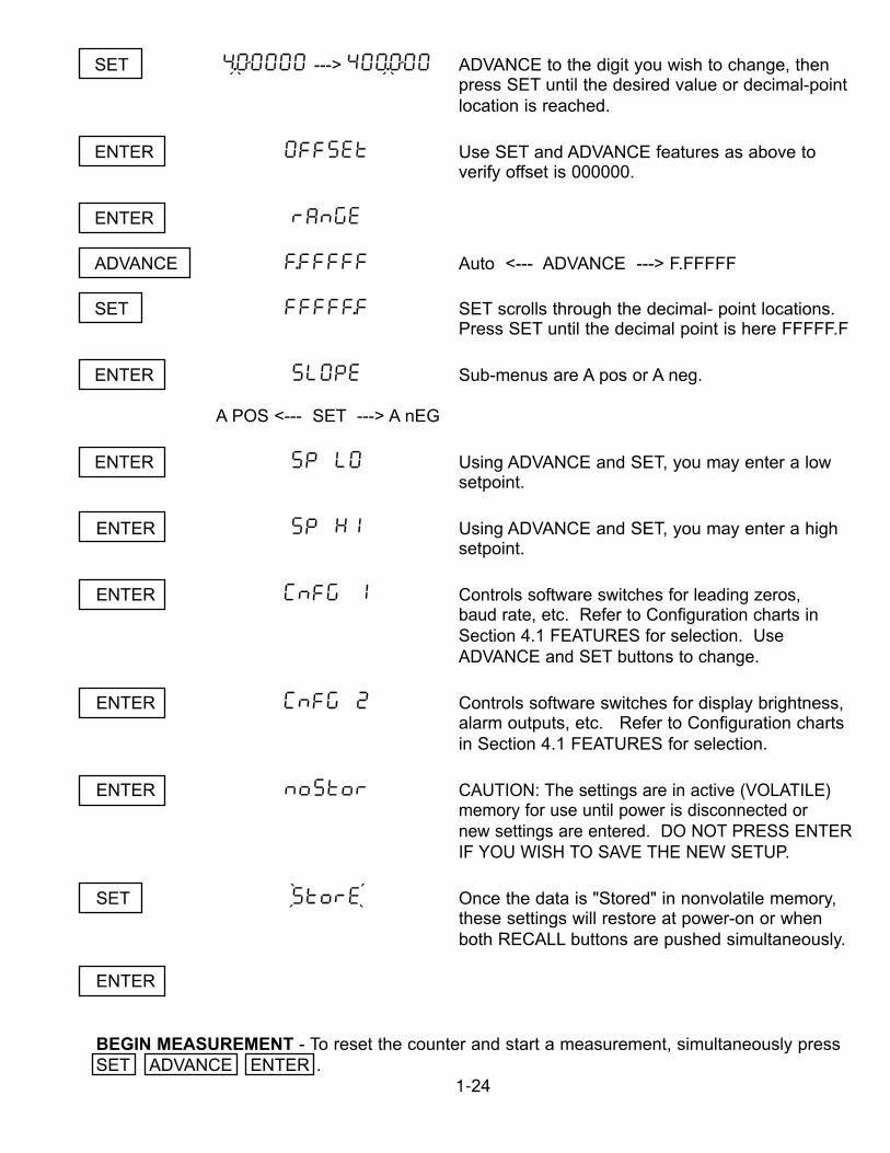
SET 4.00000 ---> 400.000 ADVANCE to the digit you wish to change, thenpress SET until the desired value or decimal-pointlocation is reached.
ENTER OFFSEt Use SET and ADVANCE features as above to verify offset is 000000.
ENTER rAnGE
ADVANCE F.FFFFF Auto <--- ADVANCE ---> F.FFFFF
SET FFFFF.F SET scrolls through the decimal- point locations.Press SET until the decimal point is here FFFFF.F
ENTER SLOPE Sub-menus are A pos or A neg.
A POS <--- SET ---> A nEG
ENTER SP LO Using ADVANCE and SET, you may enter a lowsetpoint.
ENTER SP HI Using ADVANCE and SET, you may enter a highsetpoint.
ENTER CnFG 1 Controls software switches for leading zeros, baud rate, etc. Refer to Configuration charts inSection 4.1 FEATURES for selection. Use ADVANCE and SET buttons to change.
ENTER CnFG 2 Controls software switches for display brightness,alarm outputs, etc. Refer to Configuration charts in Section 4.1 FEATURES for selection.
ENTER noStor CAUTION: The settings are in active (VOLATILE)memory for use until power is disconnected or new settings are entered. DO NOT PRESS ENTERIF YOU WISH TO SAVE THE NEW SETUP.
SET StorE Once the data is "Stored" in nonvolatile memory, these settings will restore at power-on or when both RECALL buttons are pushed simultaneously.
ENTER
BEGIN MEASUREMENT - To reset the counter and start a measurement, simultaneously pressSET ADVANCE ENTER .
1-24
` ```
`
```
``
APPENDIX AMODIFICATIONS - JUMPER DIAGRAMS
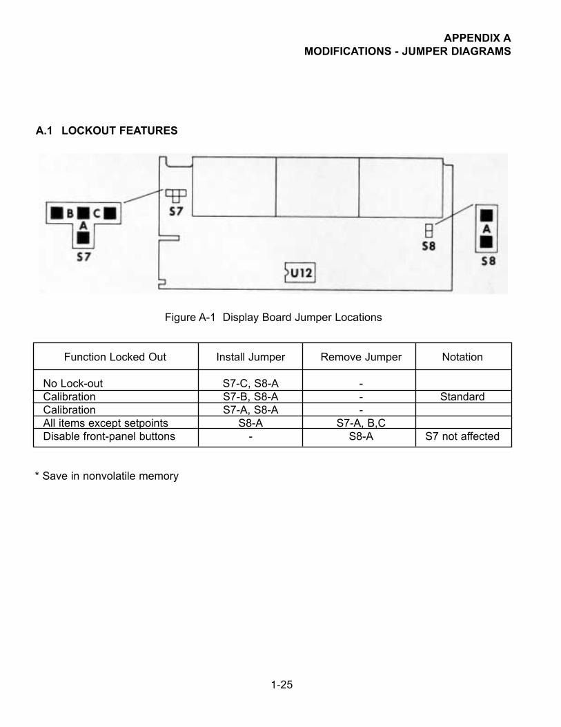
A.1 LOCKOUT FEATURES
Figure A-1 Display Board Jumper Locations
Function Locked Out Install Jumper Remove Jumper Notation
No Lock-out S7-C, S8-A -Calibration S7-B, S8-A - StandardCalibration S7-A, S8-A -All items except setpoints S8-A S7-A, B,CDisable front-panel buttons - S8-A S7 not affected
* Save in nonvolatile memory
1-25
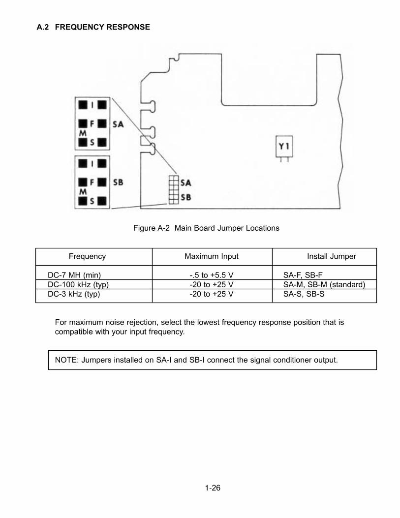
A.2 FREQUENCY RESPONSE
Figure A-2 Main Board Jumper Locations
Frequency Maximum Input Install Jumper
DC-7 MH (min) -.5 to +5.5 V SA-F, SB-FDC-100 kHz (typ) -20 to +25 V SA-M, SB-M (standard)DC-3 kHz (typ) -20 to +25 V SA-S, SB-S
For maximum noise rejection, select the lowest frequency response position that is compatible with your input frequency.
NOTE: Jumpers installed on SA-I and SB-I connect the signal conditioner output.
1-26
APPENDIX BCONTROL INPUTS/OUTPUTS
All of the control I/O lines are located on P2, a 20-pin dual row header at the rear of thecounter. A 20-position mating mass-termination connector is an option (D20D). Alternatively,a 34-pin mass-termination connector (industry standard) can be used to access both the I/Oand RS-232 lines.
RESET INPUT
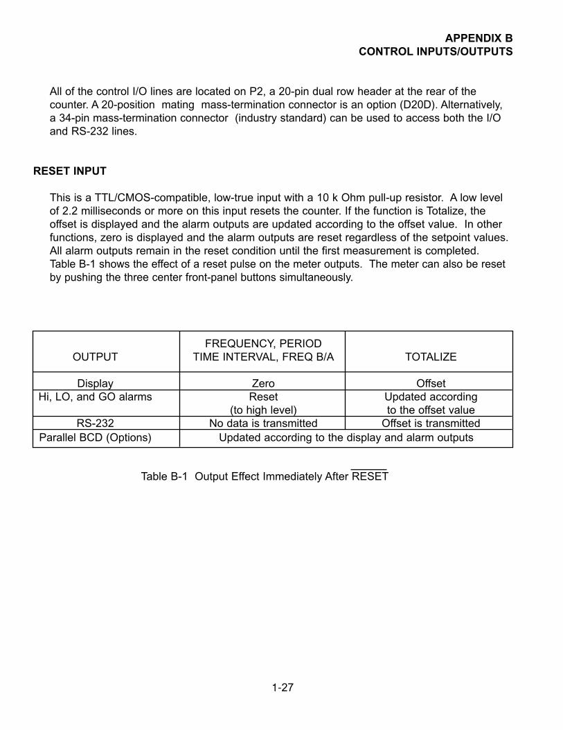
This is a TTL/CMOS-compatible, low-true input with a 10 k Ohm pull-up resistor. A low levelof 2.2 milliseconds or more on this input resets the counter. If the function is Totalize, theoffset is displayed and the alarm outputs are updated according to the offset value. In otherfunctions, zero is displayed and the alarm outputs are reset regardless of the setpoint values.All alarm outputs remain in the reset condition until the first measurement is completed.Table B-1 shows the effect of a reset pulse on the meter outputs. The meter can also be resetby pushing the three center front-panel buttons simultaneously.
FREQUENCY, PERIODOUTPUT TIME INTERVAL, FREQ B/A TOTALIZE
Display Zero OffsetHi, LO, and GO alarms Reset Updated according
(to high level) to the offset valueRS-232 No data is transmitted Offset is transmitted
Parallel BCD (Options) Updated according to the display and alarm outputs
Table B-1 Output Effect Immediately After RESET
1-27
HOLD INPUT
Except in Totalize function, the P6000A does not start a measurement when the HOLDinput is low (HOLD is true). A high level (HOLD false) of 0.1 millisecond minimum at this timestarts and completes a measurement.
In Totalize, the display is frozen and no ASCII data is transmitted when HOLD remains low fora full reading cycle. If the HOLD input goes high for 0.5 millisecond anytime during thereading cycle, the display is updated and ASCII data is transmitted. The parallel BCD data isupdated regardless of the HOLD input.
EXTERNAL GATE INPUT
This is a TTL/CMOS-compatible input with a 20 kOhm pull-up resistor. The polarity used isnormally positive (high true), but negative polarity can be selected by setting SS5 ofConfiguration 1 (CnFG 1 = X1XXXX). When the meter function is Totalize, the Ainput pulses can be gated with a signal on the External Gate input. Unlike conventionalcounters, this gating does not introduce any error.
When the meter function is Frequency, Period, or Frequency Ratio, an external gate timesignal can be connected to this input instead of using the internal gate time. In this case,SS6 of Configuration 1 should be set to disable the internal gate time (CnFG 1 = 1XXXXX).The maximum allowed Gate Time in Frequency Ratio is 80 seconds. There is no maximumlimitation in Frequency or Period. Burst frequency measurement is possible, using anexternal gate signal without disabling the internal gate time.
BLANK ENABLE INPUT/LINE FREQUENCY OUTPUT
The output is normally at high level with a 7.5 kOhm pull-up resistor. When the 50/60 Hz ACpower is present, two low-level pulses (about 3 milliseconds) appear on this output for eachAC power cycle. The signal can be tied to the A input for line frequency measurement (scalefactor = 0.5, multiplier).
This pin can also be used as an input. When tied to ground, it prevents display blanking incase of an interruption in AC power. Connection of this input to a TTL or high speed CMOS(HC Series) is not recommended since, in the presence of the AC power, it is pulled downwith a 301-ohm resistor twice per cycle.
1-28
TEST OUTPUT - DIGIT 6
This is a TTL/CMOS compatible signal. The frequency of this signal is 400.0 Hz +.1% with1/6 duty cycle. This output can drive 5 LSTTL loads.
NOTE: This is a display multiplex signal and must not be pulled down with a load of morethan .2 mA.
SPARE INVERTOR AND FLIP-FLOP
A TTL/CMOS compatible Schmitt trigger and a spare 'D' type flip-flop are provided on P2.
The inputs (clock, clear, and D) are CMOS compatible (HI level > 3.5 V, LO level < .9 V). However, a 20 k pull-up resistor is provided on clear and D inputs to make them TTL at lowfrequencies. This flip-flop can be configured to divide the clock frequency by two (connect Qoutput to the D input), thus increasing the meter maximum operating frequency to 14 MHz.
ALARM LOW, HIGH, AND GO
These are open-collector outputs corresponding to LOW and HIGH setpoints (see Section 4.1, Setpoints). Each output, if the alarm condition is active, can sink 150 mA. When the alarm condition is inactive, an output can withstand 30 V.
1-29
5.0 PROGRAMMING
5.1 GENERAL INFORMATION
The meter may be programmed using the three center pushbuttons (SET, ADVANCE andENTER) or by a personal computer through RS-232 port (connector A).
This instrument is designed to present a “serial menu” when “ENTER” pushbutton is pushed.Pushing the appropriate button rolls the display through the meter functions, parameternames and digits, repeating (for corrections) as often as desired.
This programming results in the active program by which the meter makes its measurements.At the end of the programming sequence, the choice of ‘StorE/noStor’ is provided to allow thisactive program to be preserved in the nonvolatile memory or to be used temporarily, keeping adifferent program for later use in the nonvolatile memory. The stored program can become theactive program (discarding the one currently in operation) by simultaneously pushing bothRECALL buttons.
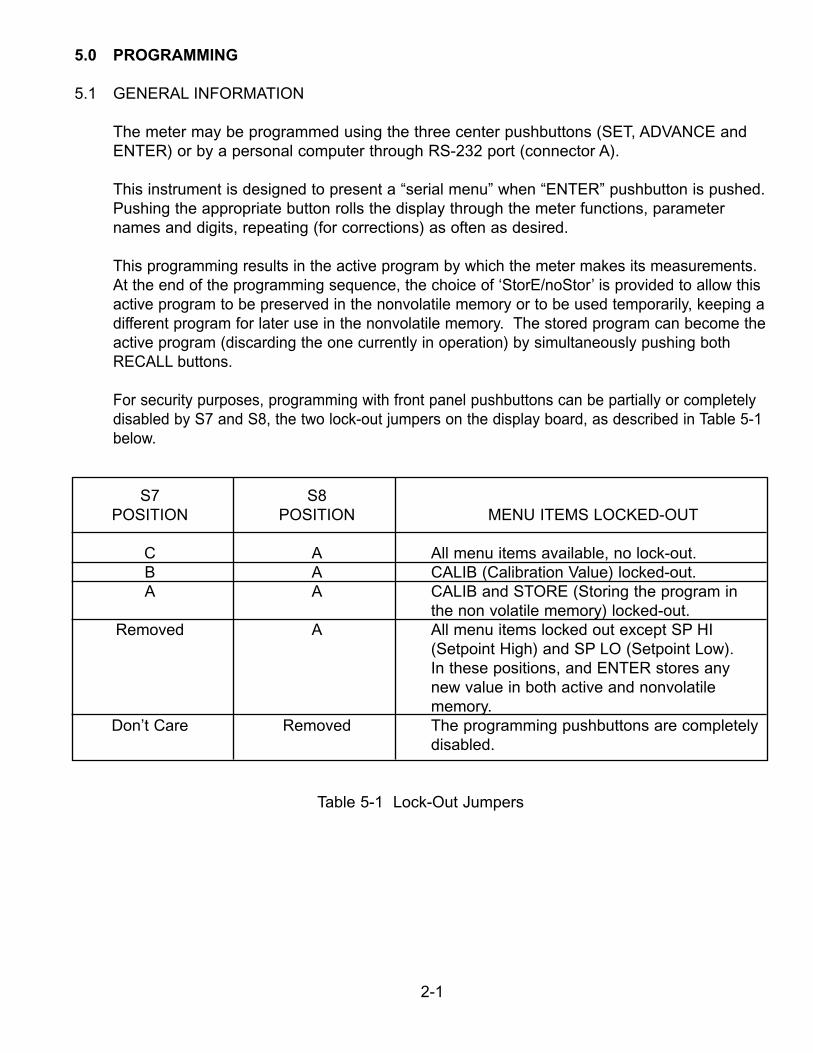
For security purposes, programming with front panel pushbuttons can be partially or completelydisabled by S7 and S8, the two lock-out jumpers on the display board, as described in Table 5-1below.
S7 S8POSITION POSITION MENU ITEMS LOCKED-OUT
C A All menu items available, no lock-out.B A CALIB (Calibration Value) locked-out.A A CALIB and STORE (Storing the program in
the non volatile memory) locked-out.Removed A All menu items locked out except SP HI
(Setpoint High) and SP LO (Setpoint Low).In these positions, and ENTER stores anynew value in both active and nonvolatilememory.
Don’t Care Removed The programming pushbuttons are completelydisabled.
Table 5-1 Lock-Out Jumpers
2-1
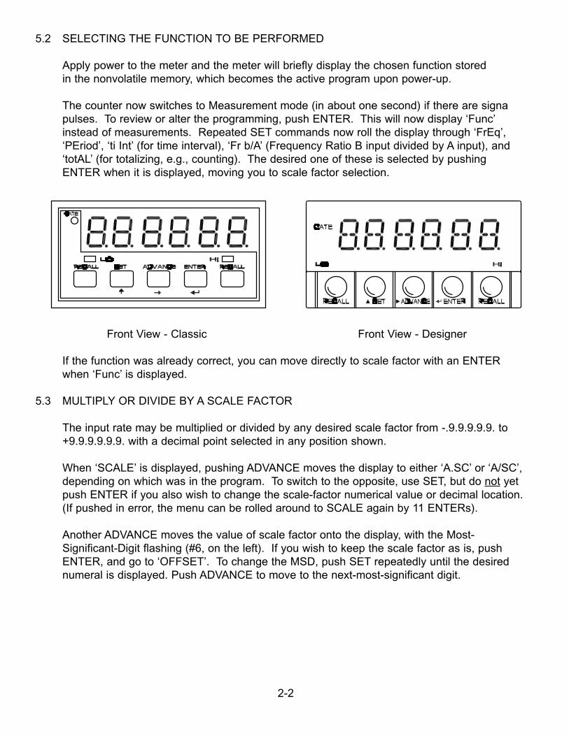
5.2 SELECTING THE FUNCTION TO BE PERFORMED
Apply power to the meter and the meter will briefly display the chosen function storedin the nonvolatile memory, which becomes the active program upon power-up.
The counter now switches to Measurement mode (in about one second) if there are signapulses. To review or alter the programming, push ENTER. This will now display ‘Func’instead of measurements. Repeated SET commands now roll the display through ‘FrEq’,‘PEriod’, ‘ti Int’ (for time interval), ‘Fr b/A’ (Frequency Ratio B input divided by A input), and‘totAL’ (for totalizing, e.g., counting). The desired one of these is selected by pushing ENTER when it is displayed, moving you to scale factor selection.
Front View - Classic Front View - Designer
If the function was already correct, you can move directly to scale factor with an ENTER when ‘Func’ is displayed.
5.3 MULTIPLY OR DIVIDE BY A SCALE FACTOR
The input rate may be multiplied or divided by any desired scale factor from -.9.9.9.9.9. to+9.9.9.9.9.9. with a decimal point selected in any position shown.
When ‘SCALE’ is displayed, pushing ADVANCE moves the display to either ‘A.SC’ or ‘A/SC’,depending on which was in the program. To switch to the opposite, use SET, but do not yetpush ENTER if you also wish to change the scale-factor numerical value or decimal location.(If pushed in error, the menu can be rolled around to SCALE again by 11 ENTERs).
Another ADVANCE moves the value of scale factor onto the display, with the Most-Significant-Digit flashing (#6, on the left). If you wish to keep the scale factor as is, pushENTER, and go to ‘OFFSET’. To change the MSD, push SET repeatedly until the desirednumeral is displayed. Push ADVANCE to move to the next-most-significant digit.
2-2
Having altered or accepted all six digits of the scale factor, one more ADVANCE allows you to reposition the decimal point, rolling it around with repeated SETs. When the decimal iscorrect, ENTER keeps the value and the multiply or divide operator.
5.4 SELECTING AN OFFSET
The meter allows the scaled measurement value to be offset by any number from -99999 to +999999 with the decimal point in any position. Pushing ADVANCE when OFFSEt is displayed moves the display to the offset value, which can be altered with the SET andADVANCE pushbuttons just like the scale factor discussed above. When the offset value iscorrect, or to accept the value shown, push ENTER; this moves the display to rAnGE.
5.5 CHOOSING AUTO-RANGING OR FIXED DISPLAY DECIMAL-POINT LOCATION
When rAnGE is shown, ADVANCE displays the active-program choice, which will be either Auto or six F’s with a flashing decimal point. The flashing denotes the location of the fixeddecimal point. The default position is FFFFFF. (d.p. = 1).
5.6 SELECTING RISING OR FALLING EDGE TRIGGERS FOR A AND B INPUTS
When SLOPE is displayed:
Push ADVANCE to display the current active program, which is A POS or A nEG. AnotherADVANCE will display the B input, B POS or B nEG. Push SET to change from positive tonegative or vice versa.
ADVANCE SETA POS b POS A POS A nEG
NOTE: B input is not used with Frequency, Period or Totalize functions; therefore, ADVANCEhas no effect.
ENTER now displays setpoint selection.
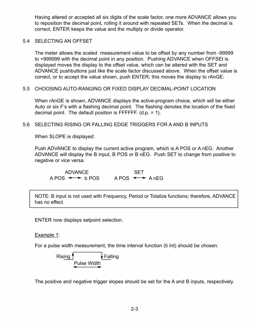
Example 1:
For a pulse width measurement, the time interval function (ti Int) should be chosen.
Rising FallingPulse Width
The positive and negative trigger slopes should be set for the A and B inputs, respectively.
2-3
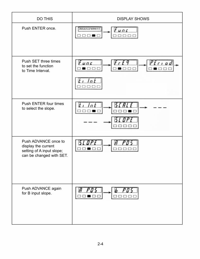
DO THIS DISPLAY SHOWS
Push ENTER once.
Push SET three timesto set the functionto Time Interval.
Push ENTER four timesto select the slope.
Push ADVANCE once todisplay the currentsetting of A input slope;can be changed with SET.
Push ADVANCE againfor B input slope.
2-4
DO THIS DISPLAY SHOWS
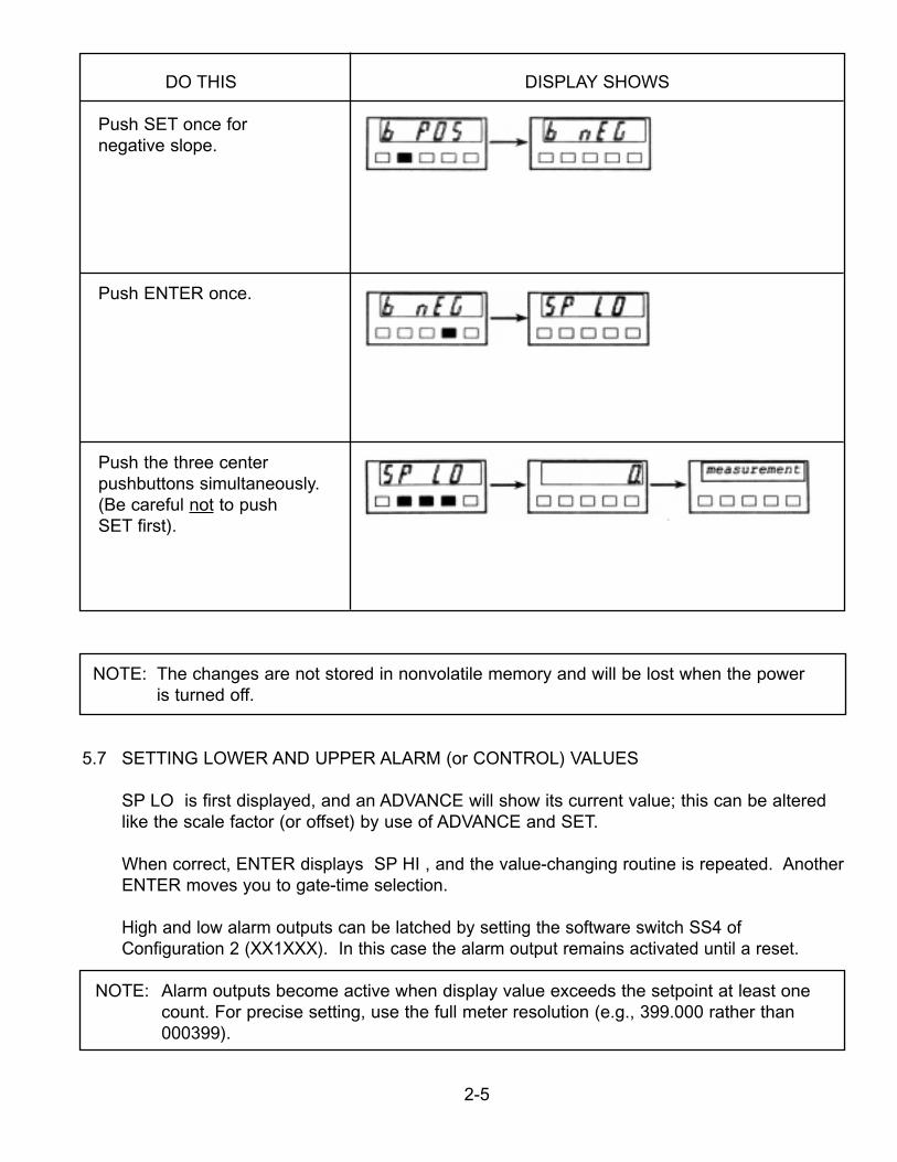
Push SET once fornegative slope.
Push ENTER once.
Push the three centerpushbuttons simultaneously.(Be careful not to pushSET first).
NOTE: The changes are not stored in nonvolatile memory and will be lost when the poweris turned off.
5.7 SETTING LOWER AND UPPER ALARM (or CONTROL) VALUES
SP LO is first displayed, and an ADVANCE will show its current value; this can be alteredlike the scale factor (or offset) by use of ADVANCE and SET.
When correct, ENTER displays SP HI , and the value-changing routine is repeated. AnotherENTER moves you to gate-time selection.
High and low alarm outputs can be latched by setting the software switch SS4 ofConfiguration 2 (XX1XXX). In this case the alarm output remains activated until a reset.
NOTE: Alarm outputs become active when display value exceeds the setpoint at least onecount. For precise setting, use the full meter resolution (e.g., 399.000 rather than000399).
2-5
5.8 SELECTING A GATE TIME
The measurement gate time is equal to this selection, from 00.00 to 99.99 seconds, plus asmall time allowance for computation/communication. (There is no gate time for totalizing, so this choice is not displayed.)
When ‘GAtE t’ is displayed, ADVANCE shows the current value (00.30 is the default); it may be altered with ADVANCE and SET (in 0.01 second increments). ENTER places that chosen value in the active program.
5.9 CONFIGURATION #1 AND #2
The last ENTER moves ‘CnFG 1’ onto the display. Here, each digit represents a softwareswitch (SSW) and any or all of them may be reset. Alternate ‘1’ and ‘0’ are displayed with SET, and ADVANCE selects the next right-hand digit, rolling around to the MSD after the LSD (right- most digit).
After setting the six software switches of the CnFG 1, an ENTER command moves the display onto CnFG 2. Again, any or all of the software switches of CnFG 2 may be set to ‘1’or ‘0’ to enable or disable a feature.
The functions of these six software switches are described in Section 4.1 .
5.10 CALIBRATION OF THE CRYSTAL FREQUENCY (CALIb displayed)
This six-digit value is the ppm (parts-per-million) fine tuning of the crystal, and it isexamined/altered by ADVANCE/SET just as the other values discussed above. The defaultsetup locks out this item from the main menu (not displayed). To view or change thecalibration value, install jumpers on S7-C and S8 of the display board. To calibrate the meter:
1. Set the function to Frequency, the Gate Time to 01.00 second and the calibration valueto zero. Other setup parameters should be the same as the default setup (Section 4.4).
2. Connect a TTL-compatible calibration source frequency to the A input. SA jumper shouldbe on the F position.
3. Note the displayed value and calculate the calibration value as follows:
CALib = 1,000,000 X (F input freq - 1)Display
4. Enter the calculated CALib and store it in the nonvolatile memory as described in thefollowing Section.
Another ENTER command moves the display to the last step, ‘noStor’.
2-6
5.11 REPLACING THE STORED PROGRAM WITH THE ACTIVE PROGRAM
At this point, a complete active program has been defined. To use it and beginmeasurements, push ENTER in response to noStor. This active program may be quitedifferent from that stored in the nonvolatile memory. It will be discarded if power isinterrupted or if RECALL is used.
This active program may also replace the stored program so that it is automaticallyrestored upon power interruption. Push SET and ‘StorE’ will be displayed. Now anENTER writes the active program into the storage and starts measurements. Thepreviously stored program is discarded.
S7 on A position prevents storing the program in nonvolatile memory.
6.0 REMOTE PROGRAMMING
6.1 GENERAL INFORMATION
The meter contains a full-duplex RS-232 port for communications. It receives setupcommands and data and sends measurement values and current setup data. It operatesa either 1200 or 9600 baud, 7 data bits, even parity and 1 stop bit. It emulates DCE (datacommunication equipment) and uses a handshake line while sending data, but none whilereceiving data. A four-wire cable is the maximum required for communications:
Transmitted dataReceived dataRequest to sendSignal ground
When connected to a computer, such as an IBM PC, and one of four commands (Put, Get,Write or Read) is received, the meter interrupts its program, receives the message, takesappropriate action, and then starts over with a new measurement. No handshake isrequired because the meter devotes its full attention to receiving the command data fromthe computer.
In the other direction, the meter sends measurement and confirming setup data to thecomputer under handshake (RTS) control. When the computer RTS output is true, data issent by the meter. When it is false, data is not sent. There are two modes of handshakingwhen sending measurement data, message and character. In the Message Handshakemode, the meter checks the RTS input from the computer when it is ready to sendmeasurement data. If the RTS is true, it sends the complete message data; if it is false, itskips sending the data completely and continues with the next measurement. In theCharacter Handshake mode, the program checks the RTS input before sending eachcharacter and does not continue with the next measurement until the current measurementhas been completely sent.
2-7
6.2 ASCII OUTPUT
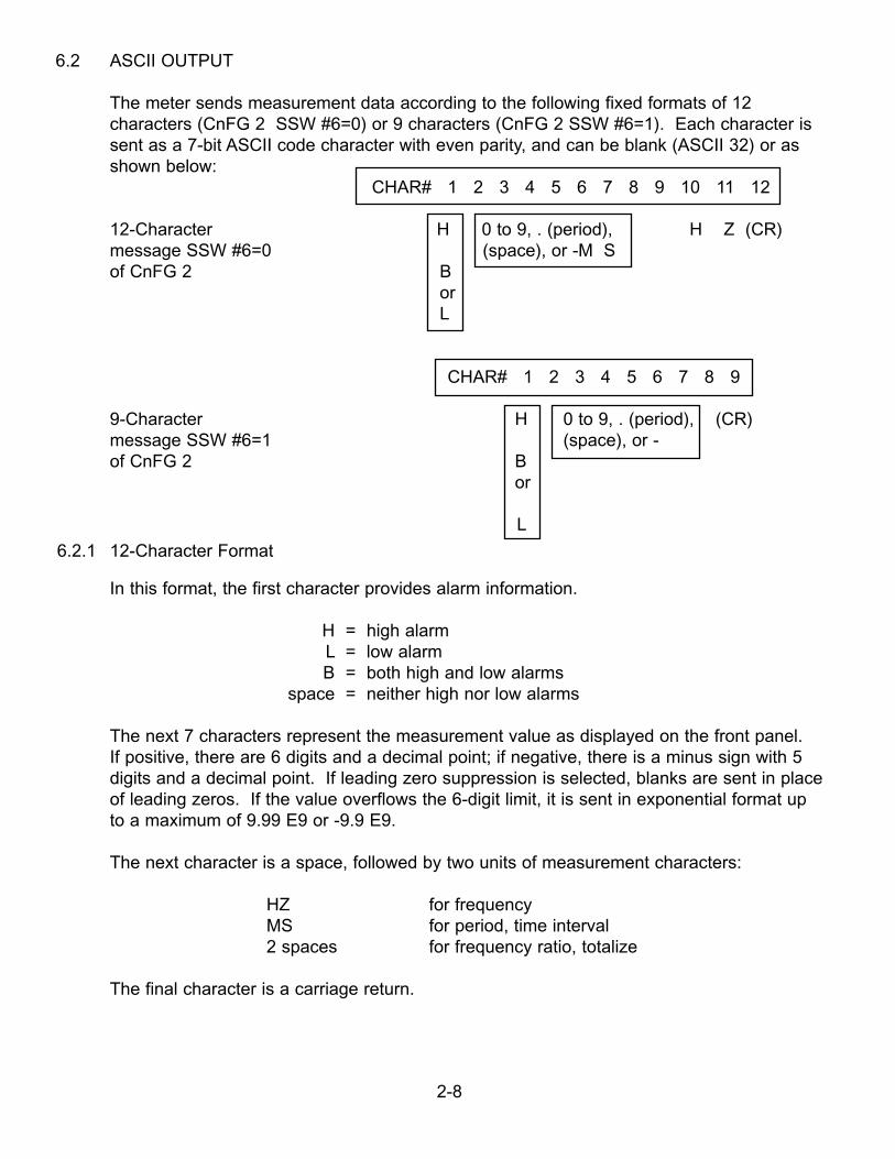
The meter sends measurement data according to the following fixed formats of 12characters (CnFG 2 SSW #6=0) or 9 characters (CnFG 2 SSW #6=1). Each character issent as a 7-bit ASCII code character with even parity, and can be blank (ASCII 32) or asshown below:
CHAR# 1 2 3 4 5 6 7 8 9 10 11 12
12-Character H 0 to 9, . (period), H Z (CR)message SSW #6=0 (space), or -M Sof CnFG 2 B
orL
CHAR# 1 2 3 4 5 6 7 8 9
9-Character H 0 to 9, . (period), (CR)message SSW #6=1 (space), or - of CnFG 2 B
or
L
6.2.1 12-Character Format
In this format, the first character provides alarm information.
H = high alarmL = low alarmB = both high and low alarms
space = neither high nor low alarms
The next 7 characters represent the measurement value as displayed on the front panel. If positive, there are 6 digits and a decimal point; if negative, there is a minus sign with 5digits and a decimal point. If leading zero suppression is selected, blanks are sent in place of leading zeros. If the value overflows the 6-digit limit, it is sent in exponential format upto a maximum of 9.99 E9 or -9.9 E9.
The next character is a space, followed by two units of measurement characters:
HZ for frequencyMS for period, time interval2 spaces for frequency ratio, totalize
The final character is a carriage return.
2-8
6.2.2 9-Character Format
The first 8 characters of this format are the same as in the 12-character format. Thespace and the units of measurement (or spaces) are omitted. The carriage return is the9th character and indicates the end of the measurement. The 9-character format is usedwhen a faster reading rate (and resulting shorter alarm response time) is more importantthan units of measurement.
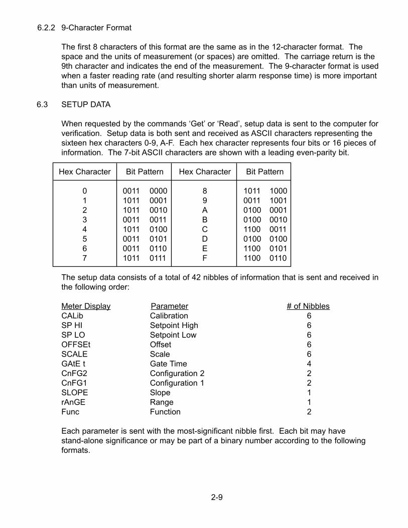
6.3 SETUP DATA
When requested by the commands ‘Get’ or ‘Read’, setup data is sent to the computer for verification. Setup data is both sent and received as ASCII characters representing thesixteen hex characters 0-9, A-F. Each hex character represents four bits or 16 pieces ofinformation. The 7-bit ASCII characters are shown with a leading even-parity bit.
Hex Character Bit Pattern Hex Character Bit Pattern
0 0011 0000 8 1011 10001 1011 0001 9 0011 10012 1011 0010 A 0100 00013 0011 0011 B 0100 00104 1011 0100 C 1100 00115 0011 0101 D 0100 01006 0011 0110 E 1100 01017 1011 0111 F 1100 0110
The setup data consists of a total of 42 nibbles of information that is sent and received inthe following order:
Meter Display Parameter # of NibblesCALib Calibration 6SP HI Setpoint High 6SP LO Setpoint Low 6OFFSEt Offset 6SCALE Scale 6GAtE t Gate Time 4CnFG2 Configuration 2 2CnFG1 Configuration 1 2SLOPE Slope 1rAnGE Range 1Func Function 2
Each parameter is sent with the most-significant nibble first. Each bit may have stand-alone significance or may be part of a binary number according to the followingformats.
2-9
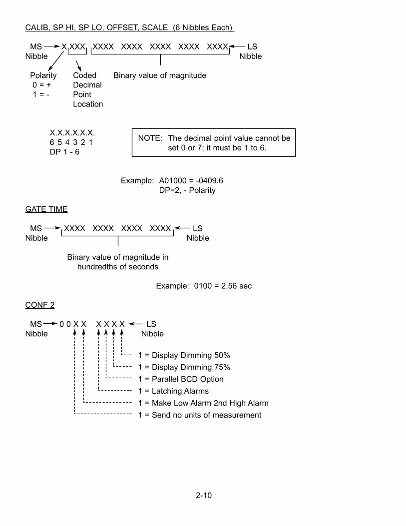
CALIB, SP HI, SP LO, OFFSET, SCALE (6 Nibbles Each)
MS X XXX XXXX XXXX XXXX XXXX XXXX LSNibble Nibble
Polarity Coded Binary value of magnitude0 = + Decimal1 = - Point
Location
X.X.X.X.X.X.6 5 4 3 2 1DP 1 - 6
Example: A01000 = -0409.6DP=2, - Polarity
GATE TIME
MS XXXX XXXX XXXX XXXX LSNibble Nibble
Binary value of magnitude in hundredths of seconds
Example: 0100 = 2.56 sec
CONF 2
MS 0 0 X X X X X X LSNibble Nibble
1 = Display Dimming 50%
1 = Display Dimming 75%
1 = Parallel BCD Option
1 = Latching Alarms
1 = Make Low Alarm 2nd High Alarm
1 = Send no units of measurement
2-10
NOTE: The decimal point value cannot beset 0 or 7; it must be 1 to 6.
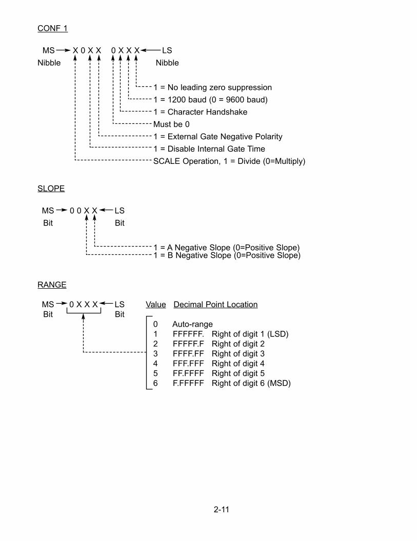
CONF 1
MS X 0 X X 0 X X X LS
Nibble Nibble
1 = No leading zero suppression
1 = 1200 baud (0 = 9600 baud)
1 = Character Handshake
Must be 0
1 = External Gate Negative Polarity
1 = Disable Internal Gate Time
SCALE Operation, 1 = Divide (0=Multiply)
SLOPE
MS 0 0 X X LS
Bit Bit
1 = A Negative Slope (0=Positive Slope)1 = B Negative Slope (0=Positive Slope)
RANGE
MS 0 X X X LS Value Decimal Point LocationBit Bit
0 Auto-range 1 FFFFFF. Right of digit 1 (LSD)2 FFFFF.F Right of digit 23 FFFF.FF Right of digit 34 FFF.FFF Right of digit 45 FF.FFFF Right of digit 5 6 F.FFFFF Right of digit 6 (MSD)
2-11
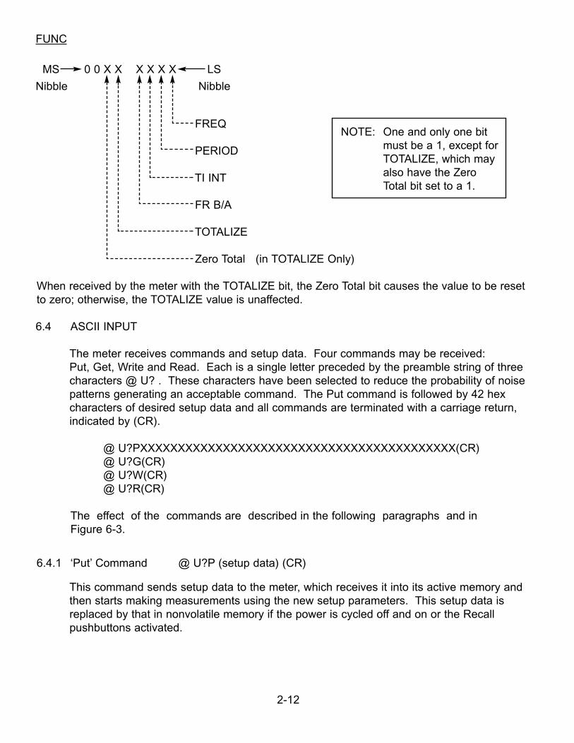
FUNC
MS 0 0 X X X X X X LS
Nibble Nibble
FREQ
PERIOD
TI INT
FR B/A
TOTALIZE
Zero Total (in TOTALIZE Only)
When received by the meter with the TOTALIZE bit, the Zero Total bit causes the value to be reset to zero; otherwise, the TOTALIZE value is unaffected.
6.4 ASCII INPUT
The meter receives commands and setup data. Four commands may be received: Put, Get, Write and Read. Each is a single letter preceded by the preamble string of threecharacters @ U? . These characters have been selected to reduce the probability of noisepatterns generating an acceptable command. The Put command is followed by 42 hexcharacters of desired setup data and all commands are terminated with a carriage return,indicated by (CR).
@ U?PXXXXXXXXXXXXXXXXXXXXXXXXXXXXXXXXXXXXXXXXXX(CR)@ U?G(CR)@ U?W(CR)@ U?R(CR)
The effect of the commands are described in the following paragraphs and in Figure 6-3.
6.4.1 ‘Put’ Command @ U?P (setup data) (CR)
This command sends setup data to the meter, which receives it into its active memory andthen starts making measurements using the new setup parameters. This setup data isreplaced by that in nonvolatile memory if the power is cycled off and on or the Recallpushbuttons activated.
2-12
NOTE: One and only one bit must be a 1, except forTOTALIZE, which mayalso have the Zero Total bit set to a 1.
6.4.2 ‘Get’ Command @ U?G (CR)
This command requests the meter to send the current setup parameters in the activememory to the computer. It is normally used after the Put command to verify correctreception of the setup parameters by the meter.
6.4.3 ‘Write’ Command @ U?W (CR)
This command transfers the setup data in the meter’s active memory (active program) tononvolatile memory (stored program). If it is desired to have a different program activebut not stored, this may be sent with a new ‘Put’ command or, if not locked out, enteredfrom the keyboard. Setup data in nonvolatile memory is then transferred back to theactive memory when power is cycled off and on or the Recall pushbuttons activated.
6.4.4 ‘Read’ Command @ U?R (CR)
This command requests the meter to read (transfer) the setup data in nonvolatile memoryinto the active memory for use in the measurements that follow and to send this setupdata to the computer.
6.5 INTERFACING EXAMPLES
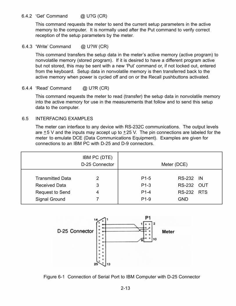
The meter can interface to any device with RS-232C communications. The output levelsare +5 V and the inputs may accept up to +25 V. The pin connections are labeled for themeter to emulate DCE (Data Communications Equipment). Examples are given forconnections to an IBM PC with D-25 and D-9 connectors.
IBM PC (DTE)
D-25 Connector Meter (DCE)
Transmitted Data 2 P1-5 RS-232 IN
Received Data 3 P1-3 RS-232 OUT
Request to Send 4 P1-4 RS-232 RTS
Signal Ground 7 P1-9 GND
Figure 6-1 Connection of Serial Port to IBM Computer with D-25 Connector
2-13
Meter
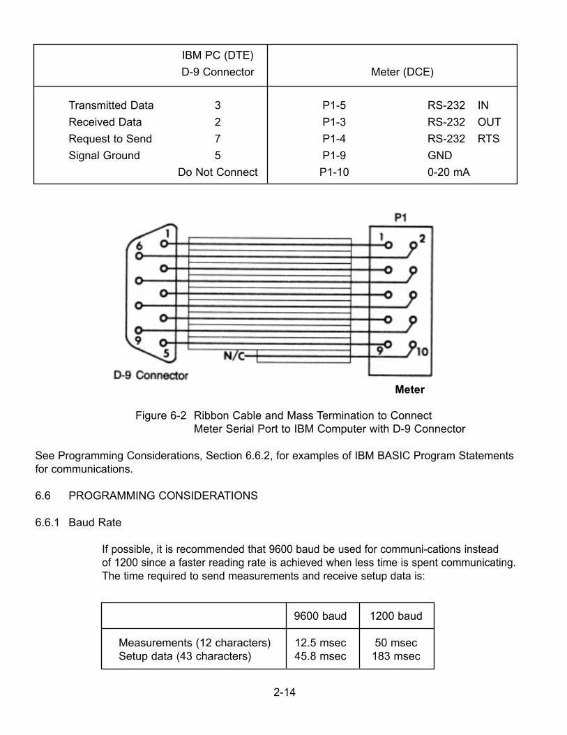
IBM PC (DTE)
D-9 Connector Meter (DCE)
Transmitted Data 3 P1-5 RS-232 IN
Received Data 2 P1-3 RS-232 OUT
Request to Send 7 P1-4 RS-232 RTS
Signal Ground 5 P1-9 GND
Do Not Connect P1-10 0-20 mA
Figure 6-2 Ribbon Cable and Mass Termination to ConnectMeter Serial Port to IBM Computer with D-9 Connector
See Programming Considerations, Section 6.6.2, for examples of IBM BASIC Program Statementsfor communications.
6.6 PROGRAMMING CONSIDERATIONS
6.6.1 Baud Rate
If possible, it is recommended that 9600 baud be used for communi-cations insteadof 1200 since a faster reading rate is achieved when less time is spent communicating.The time required to send measurements and receive setup data is:
9600 baud 1200 baud
Measurements (12 characters) 12.5 msec 50 msecSetup data (43 characters) 45.8 msec 183 msec
2-14
Meter
If the application program is to initiate communications with the meter and the initia baudrate setting of the meter is unknown, it is possible to write the application program toperform a Get command at 9600 baud rate. If that fails, change baud rate of the externaldevice to 1200 and try again. Once communication is established at the same baud rate,it may be changed by sending new setup data with the desired baud rate.
6.6.2 Communication Control Programming
The following statements written in IBM BASICA are suggested for inclusion in anapplication program written for the meter.
1. CLOSE 1: OPEN “COM1:9600,E,7,1,RS,CS,DS” AS #1
This opens the IBM communications file for 9600 baud, even parity, 7-bit word and 1 stopbit. RTS is made false to begin with and the CTS and DSR handshake lines are ignored.Two stop bits could also be used but would only lengthen the communications time. If theIBM communications port is COM2, change COM1 above to COM2 and 3FC to 2FC in 2and 3 below.
2. 3000 OUT &H3FC,INP(&H3FC) AND &HFD:RETURN
This subroutine resets the RTS output of the IBM to low (false). RTS false prevents themeter from sending readings.
3. 3100 OUT &H3FC,INP(&H3FC) OR &H02:RETURN
This subroutine sets the RTS output of the IBM to high (true). RTS true allows theP6000A/P5000 to send readings.
4. 4000 IF LOC(1)=0 THEN 40304010 ON ERROR GOTO 40404020 A$=INPUT$(LOC(1),#1)4030 ON ERROR GOTO 0:RETURN4040 RESUME 4000
This subroutine empties the input buffer, and does it without a program-terminating errorwhenever the buffer is full. If the statement on line 4020 is executed by itself when thebuffer is full, an error is generated.
5. PRINT #1, ‘@U?P’ + SETUP$
This sends the setup data of 42 hex characters in SETUP$ to the meter.
2-15
6. PRINT #1, ‘@U?G’PRINT #1, ‘@U?R’
The first statement requests that the setup data be sent from the meter to the IBM computer.The second statement requests that the setup data be transferred from nonvolatile memory to active memory before being sent.
7. PRINT #1, ‘@U?W’
This writes (transfers) data from the meter’s active memory to the nonvolatile memory.
8. 1000 GOSUB 4000 ‘EMPTY INPUT BUFFER1010 B$=’’’’ ‘HOLDS CUMULATIVE INPUT DATA1020 GOSUB 3100 ‘MAKE RTS TRUE TO START P6000A
SENDING DATA1030 IF LOC(1)=0 THEN 1030 ‘WAIT FOR DATA1040 A$=INPUT$(LOC(1),#1) ‘GET DATA FROM INPUT BUFFER1050 B$=B$+A$ ‘CONCATENATE CHARACTERS1060 CR=INSTR(B$,CHR$(13)) ‘FIND LOCATION OF CARRIAGE RETURN1070 IF CR=0 THEN 1030 ‘IF NOT RECEIVED YET, REPEAT1080 A$=LEFT$(B$,CR-1) ‘THE VALUE IS ALL CHARS UP TO THE
CARRIAGE RETURN1090 GOSUB 3000 ‘MAKE RTS FALSE TO STOP P6000A FROM
SENDING DATA
This reads the data sent from the meter to the IBM PC.
9. To read data continuously, add the following:
1100 B$=MID$(B$,CR+1) ‘STRIP THE READING FROM THE STRING1110 GOSUB XXXX ‘DO SOMETHING WITH THE DATA IN A$1120 GOTO 1020 ‘READ MORE DATA
2-16
To read the meter output from the computer screen, use the following program which waswritten in IBM BASICA.
10 ‘ READ.BAS100 SCREEN 0:CLS:KEY OFF:CLOSE130 CR$=CHR$(13)160 PRINT:PRINT “SET THE P6000A/P5000 TO 9600 BAUD.”180 PRINT:INPUT “ENTER COM1 (1) OR COM2 (2) RS-232 PORT “;W185 PRINT:INPUT “INCLUDE UNITS OF MEASUREMENT (Y/N) “;K$186 IF (K$ = “Y” OR K$ = “y”) THEN LN = 11 ELSE LN = 8190 IF W=1 THEN COMM$=”COM1” ELSE COMM$ = “COM2”500 ‘ ======================= Open serial communications530 CLOSE:OPEN COMM$+”:9600,E,7,1,CS,DS” AS #1540 CLS1000 ‘ ======================== Start main program1010 GOSUB 5030 ‘CLEAR INPUT BUFFER1050 IF INKEY$=CHR$(27) THEN 20001060 IF LOC(1)=0 THEN 10501070 A$=INPUT$(LOC(1),#1) ‘READ RECORD1080 B$=B$+A$1090 Q=INSTR(B$,CR$)1100 IF Q=0 THEN 10501110 A$=LEFT$(B$,Q-1)1120 B$=MID$(B$,Q+1)1130 IF LEN(A$) < > LN THEN 10501150 PRINT A$1160 GOTO 10502000 ‘ ========================2010 PRINT “ESC=EXIT CR=CONT “;2020 PRINT “?”;
2030 KY$=INKEY$:IF KY$=CHR$(27) THEN 20802040 IF KY$=CHR$(13) THEN CLS : GOTO 10102070 IF KY$=”” THEN 2030
2080 CLOSE :SCREEN 0:END ‘ ============ Exit here5000 ‘********************************************
5010 ‘* CLEAR INPUT BUFFER * 5020 ‘********************************************5030 IF LOC(1)=0 THEN 50605040 ON ERROR GOTO 50705050 A$=INPUT$(LOC(1),#1)5060 ON ERROR GOTO 0:RETURN5070 RESUME 5030
To change the meter’s setup data or to monitor the readings, use the SB02 Option whichprovides a complete menu-driven program.
2-17
6.7 PARITY CHECKING
Although the meter includes an even parity bit with data sent out on the RS-232C interface,it does not check the data received for even parity.
6.8 TIMING
When a Put command is sent to the meter, it is accompanied by a string of 42 setupcharacters. The statement PRINT #1, @U?P + SETUP$ puts the string into an output bufferfor transmission and the BASIC program continues while the data is being transmitted. Ifwithin a few lines, the statement PRINT #1, @U?G is executed, the @U?G is added to theend of the setup string in the buffer which is still being transmitted. This causes the @U?Gcharacters to be missed because each transmission from the computer must be completelyreceived by the meter and the next measurement started before another command is issued.A statement FOR J=1 TO 300:NEXT J introduces enough delay to allow separation betweencommands.
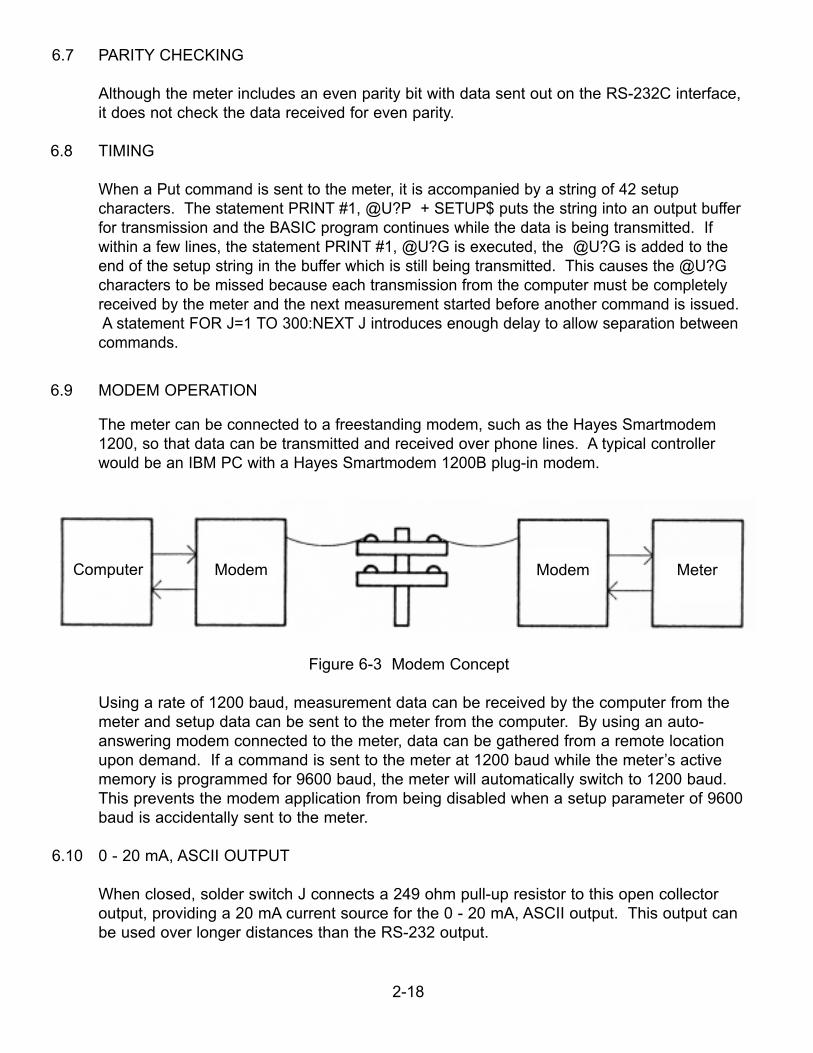
6.9 MODEM OPERATION
The meter can be connected to a freestanding modem, such as the Hayes Smartmodem 1200, so that data can be transmitted and received over phone lines. A typical controller would be an IBM PC with a Hayes Smartmodem 1200B plug-in modem.
Figure 6-3 Modem Concept
Using a rate of 1200 baud, measurement data can be received by the computer from themeter and setup data can be sent to the meter from the computer. By using an auto-answering modem connected to the meter, data can be gathered from a remote location upon demand. If a command is sent to the meter at 1200 baud while the meter’s activememory is programmed for 9600 baud, the meter will automatically switch to 1200 baud.This prevents the modem application from being disabled when a setup parameter of 9600baud is accidentally sent to the meter.
6.10 0 - 20 mA, ASCII OUTPUT
When closed, solder switch J connects a 249 ohm pull-up resistor to this open collectoroutput, providing a 20 mA current source for the 0 - 20 mA, ASCII output. This output can be used over longer distances than the RS-232 output.
2-18
MeterModemModemComputer
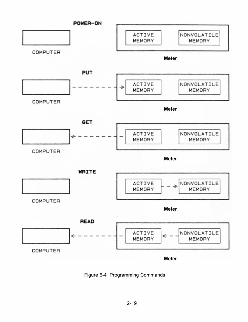
Figure 6-4 Programming Commands
2-19
Meter
Meter
Meter
Meter
Meter
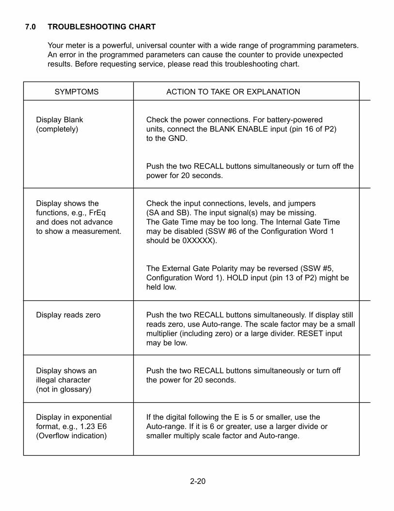
7.0 TROUBLESHOOTING CHART
Your meter is a powerful, universal counter with a wide range of programming parameters.An error in the programmed parameters can cause the counter to provide unexpectedresults. Before requesting service, please read this troubleshooting chart.
SYMPTOMS ACTION TO TAKE OR EXPLANATION
Display Blank Check the power connections. For battery-powered(completely) units, connect the BLANK ENABLE input (pin 16 of P2)
to the GND.
Push the two RECALL buttons simultaneously or turn off thepower for 20 seconds.
Display shows the Check the input connections, levels, and jumpersfunctions, e.g., FrEq (SA and SB). The input signal(s) may be missing.and does not advance The Gate Time may be too long. The Internal Gate Timeto show a measurement. may be disabled (SSW #6 of the Configuration Word 1
should be 0XXXXX).
The External Gate Polarity may be reversed (SSW #5,Configuration Word 1). HOLD input (pin 13 of P2) might beheld low.
Display reads zero Push the two RECALL buttons simultaneously. If display stillreads zero, use Auto-range. The scale factor may be a smallmultiplier (including zero) or a large divider. RESET input may be low.
Display shows an Push the two RECALL buttons simultaneously or turn offillegal character the power for 20 seconds.(not in glossary)
Display in exponential If the digital following the E is 5 or smaller, use theformat, e.g., 1.23 E6 Auto-range. If it is 6 or greater, use a larger divide or (Overflow indication) smaller multiply scale factor and Auto-range.
2-20
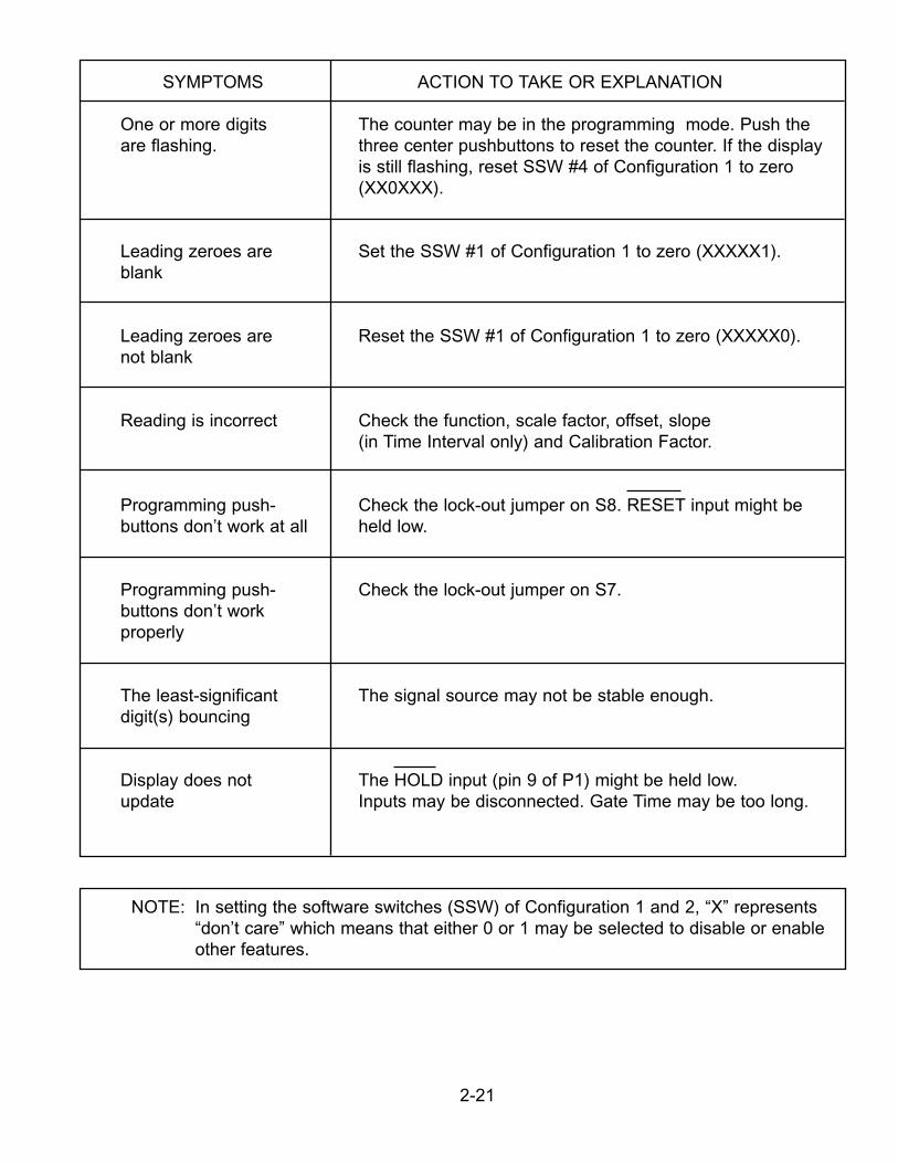
SYMPTOMS ACTION TO TAKE OR EXPLANATION
One or more digits The counter may be in the programming mode. Push theare flashing. three center pushbuttons to reset the counter. If the display
is still flashing, reset SSW #4 of Configuration 1 to zero(XX0XXX).
Leading zeroes are Set the SSW #1 of Configuration 1 to zero (XXXXX1).blank
Leading zeroes are Reset the SSW #1 of Configuration 1 to zero (XXXXX0).not blank
Reading is incorrect Check the function, scale factor, offset, slope(in Time Interval only) and Calibration Factor.
Programming push- Check the lock-out jumper on S8. RESET input might bebuttons don’t work at all held low.
Programming push- Check the lock-out jumper on S7.buttons don’t workproperly
The least-significant The signal source may not be stable enough.digit(s) bouncing
Display does not The HOLD input (pin 9 of P1) might be held low.update Inputs may be disconnected. Gate Time may be too long.
NOTE: In setting the software switches (SSW) of Configuration 1 and 2, “X” represents“don’t care” which means that either 0 or 1 may be selected to disable or enableother features.
2-21
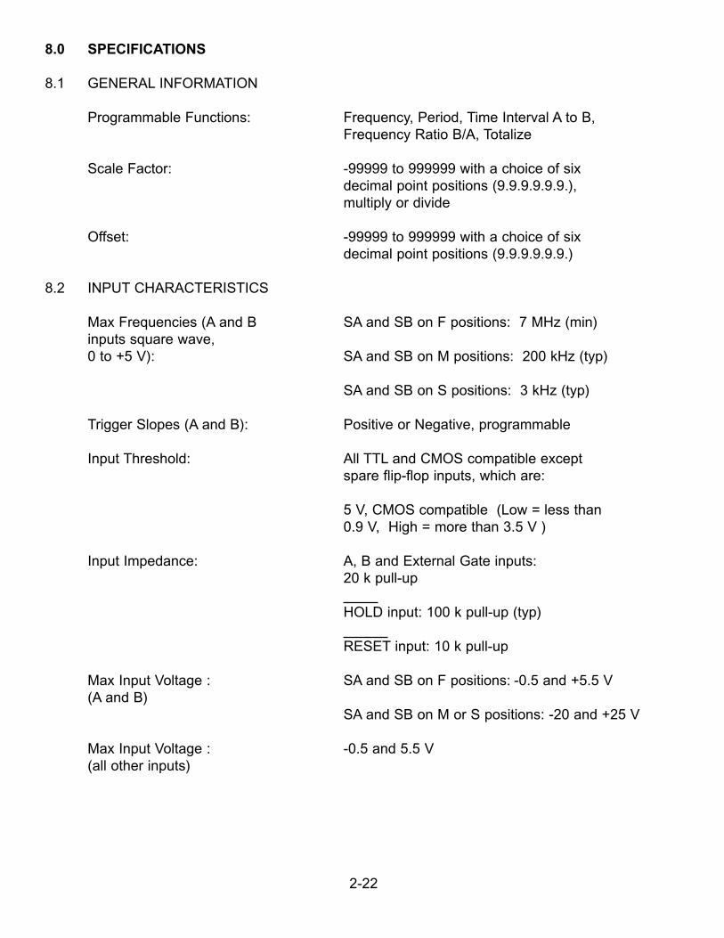
8.0 SPECIFICATIONS
8.1 GENERAL INFORMATION
Programmable Functions: Frequency, Period, Time Interval A to B,Frequency Ratio B/A, Totalize
Scale Factor: -99999 to 999999 with a choice of sixdecimal point positions (9.9.9.9.9.9.),multiply or divide
Offset: -99999 to 999999 with a choice of sixdecimal point positions (9.9.9.9.9.9.)
8.2 INPUT CHARACTERISTICS
Max Frequencies (A and B SA and SB on F positions: 7 MHz (min)inputs square wave,0 to +5 V): SA and SB on M positions: 200 kHz (typ)
SA and SB on S positions: 3 kHz (typ)
Trigger Slopes (A and B): Positive or Negative, programmable
Input Threshold: All TTL and CMOS compatible exceptspare flip-flop inputs, which are:
5 V, CMOS compatible (Low = less than0.9 V, High = more than 3.5 V )
Input Impedance: A, B and External Gate inputs:20 k pull-up
HOLD input: 100 k pull-up (typ)
RESET input: 10 k pull-up
Max Input Voltage : SA and SB on F positions: -0.5 and +5.5 V(A and B)
SA and SB on M or S positions: -20 and +25 V
Max Input Voltage : -0.5 and 5.5 V(all other inputs)
2-22
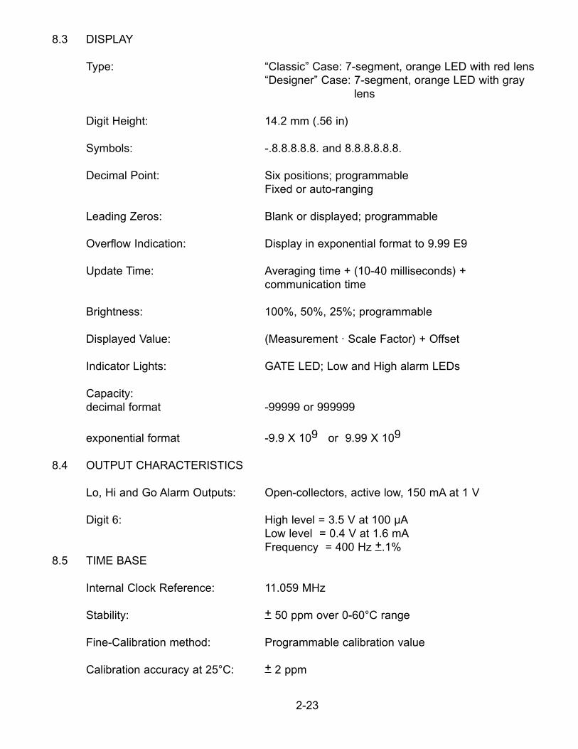
8.3 DISPLAY
Type: “Classic” Case: 7-segment, orange LED with red lens“Designer” Case: 7-segment, orange LED with gray
lens
Digit Height: 14.2 mm (.56 in)
Symbols: -.8.8.8.8.8. and 8.8.8.8.8.8.
Decimal Point: Six positions; programmable Fixed or auto-ranging
Leading Zeros: Blank or displayed; programmable
Overflow Indication: Display in exponential format to 9.99 E9
Update Time: Averaging time + (10-40 milliseconds) +communication time
Brightness: 100%, 50%, 25%; programmable
Displayed Value: (Measurement · Scale Factor) + Offset
Indicator Lights: GATE LED; Low and High alarm LEDs
Capacity:decimal format -99999 or 999999
exponential format -9.9 X 10⁹ or 9.99 X 10⁹
8.4 OUTPUT CHARACTERISTICS
Lo, Hi and Go Alarm Outputs: Open-collectors, active low, 150 mA at 1 V
Digit 6: High level = 3.5 V at 100 µALow level = 0.4 V at 1.6 mAFrequency = 400 Hz +.1%
8.5 TIME BASE
Internal Clock Reference: 11.059 MHz
Stability: + 50 ppm over 0-60°C range
Fine-Calibration method: Programmable calibration value
Calibration accuracy at 25°C: + 2 ppm
2-23
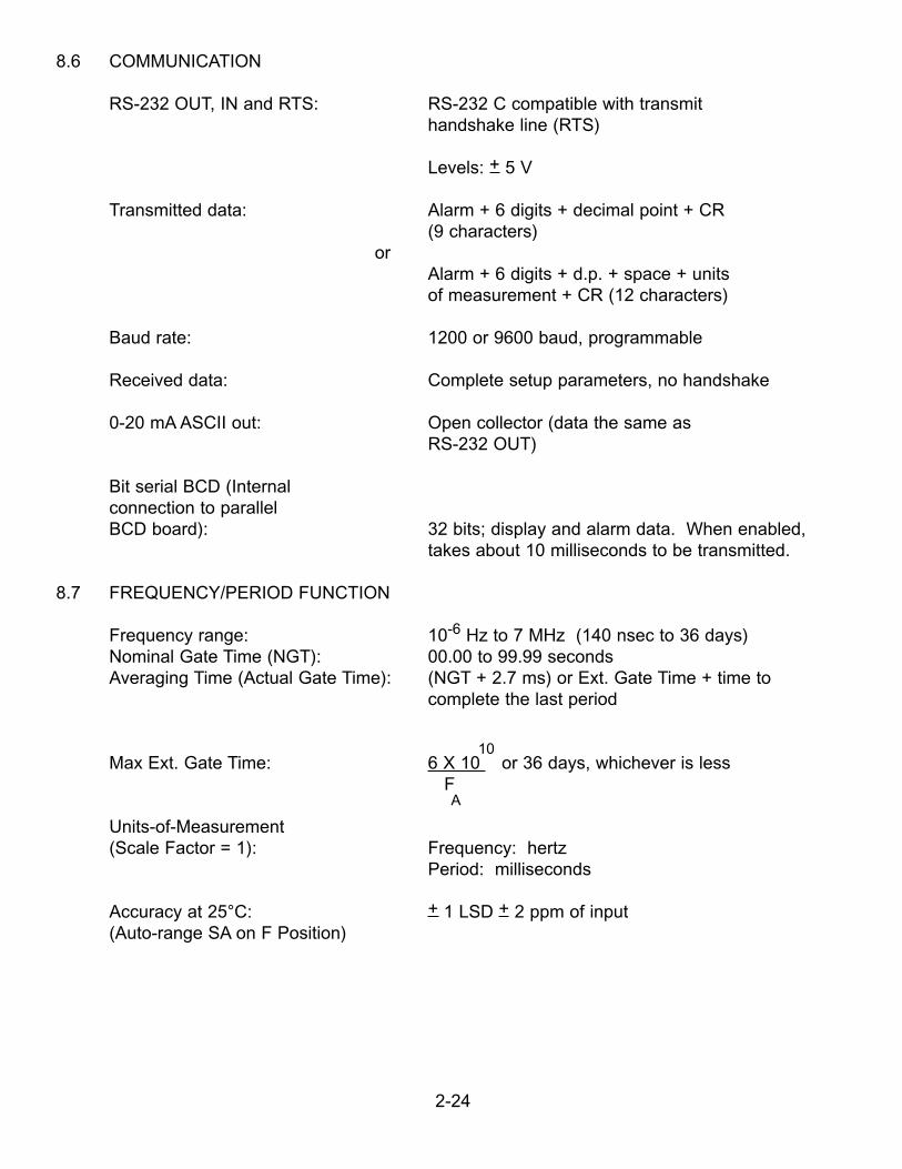
8.6 COMMUNICATION
RS-232 OUT, IN and RTS: RS-232 C compatible with transmithandshake line (RTS)
Levels: + 5 V
Transmitted data: Alarm + 6 digits + decimal point + CR(9 characters)
orAlarm + 6 digits + d.p. + space + unitsof measurement + CR (12 characters)
Baud rate: 1200 or 9600 baud, programmable
Received data: Complete setup parameters, no handshake
0-20 mA ASCII out: Open collector (data the same as RS-232 OUT)
Bit serial BCD (Internalconnection to parallel BCD board): 32 bits; display and alarm data. When enabled,
takes about 10 milliseconds to be transmitted.
8.7 FREQUENCY/PERIOD FUNCTION
Frequency range: 10-6 Hz to 7 MHz (140 nsec to 36 days)Nominal Gate Time (NGT): 00.00 to 99.99 secondsAveraging Time (Actual Gate Time): (NGT + 2.7 ms) or Ext. Gate Time + time to
complete the last period
10Max Ext. Gate Time: 6 X 10 or 36 days, whichever is less
FA
Units-of-Measurement(Scale Factor = 1): Frequency: hertz
Period: milliseconds
Accuracy at 25°C: + 1 LSD + 2 ppm of input(Auto-range SA on F Position)
2-24
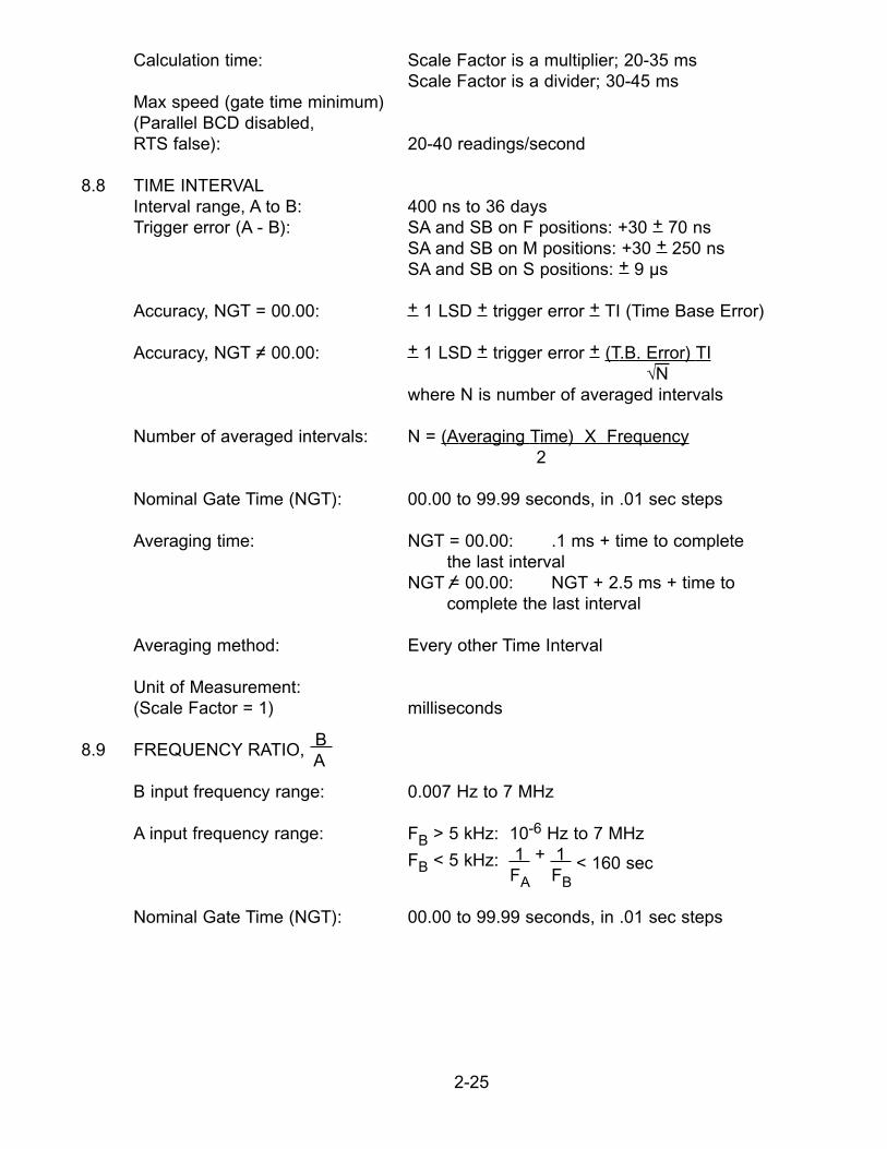
Calculation time: Scale Factor is a multiplier; 20-35 msScale Factor is a divider; 30-45 ms
Max speed (gate time minimum)(Parallel BCD disabled, RTS false): 20-40 readings/second
8.8 TIME INTERVALInterval range, A to B: 400 ns to 36 daysTrigger error (A - B): SA and SB on F positions: +30 + 70 ns
SA and SB on M positions: +30 + 250 nsSA and SB on S positions: + 9 µs
Accuracy, NGT = 00.00: + 1 LSD + trigger error + TI (Time Base Error)
Accuracy, NGT = 00.00: + 1 LSD + trigger error + (T.B. Error) TI√N
where N is number of averaged intervals
Number of averaged intervals: N = (Averaging Time) X Frequency2
Nominal Gate Time (NGT): 00.00 to 99.99 seconds, in .01 sec steps
Averaging time: NGT = 00.00: .1 ms + time to completethe last interval
NGT = 00.00: NGT + 2.5 ms + time tocomplete the last interval
Averaging method: Every other Time Interval
Unit of Measurement:(Scale Factor = 1) milliseconds
8.9 FREQUENCY RATIO, B A
B input frequency range: 0.007 Hz to 7 MHz
A input frequency range: FB > 5 kHz: 10-6 Hz to 7 MHz
FB < 5 kHz: 1 + 1 < 160 secFA FB
Nominal Gate Time (NGT): 00.00 to 99.99 seconds, in .01 sec steps
2-25
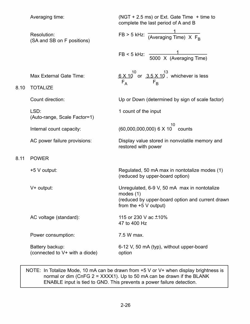
Averaging time: (NGT + 2.5 ms) or Ext. Gate Time + time tocomplete the last period of A and B
Resolution: FB > 5 kHz: 1
(SA and SB on F positions)(Averaging Time) X FB
FB < 5 kHz: 1 5000 X (Averaging Time)
10 13Max External Gate Time: 6 X 10 or 3.5 X 10 , whichever is less
FA FB8.10 TOTALIZE
Count direction: Up or Down (determined by sign of scale factor)
LSD: 1 count of the input(Auto-range, Scale Factor=1)
10Internal count capacity: (60,000,000,000) 6 X 10 counts
AC power failure provisions: Display value stored in nonvolatile memory andrestored with power
8.11 POWER
+5 V output: Regulated, 50 mA max in nontotalize modes (1)(reduced by upper-board option)
V+ output: Unregulated, 6-9 V, 50 mA max in nontotalizemodes (1)(reduced by upper-board option and current drawnfrom the +5 V output)
AC voltage (standard): 115 or 230 V ac +10%47 to 400 Hz
Power consumption: 7.5 W max.
Battery backup: 6-12 V, 50 mA (typ), without upper-board(connected to V+ with a diode) option
NOTE: In Totalize Mode, 10 mA can be drawn from +5 V or V+ when display brightness isnormal or dim (CnFG 2 = XXXX1). Up to 50 mA can be drawn if the BLANK ENABLE input is tied to GND. This prevents a power failure detection.
2-26
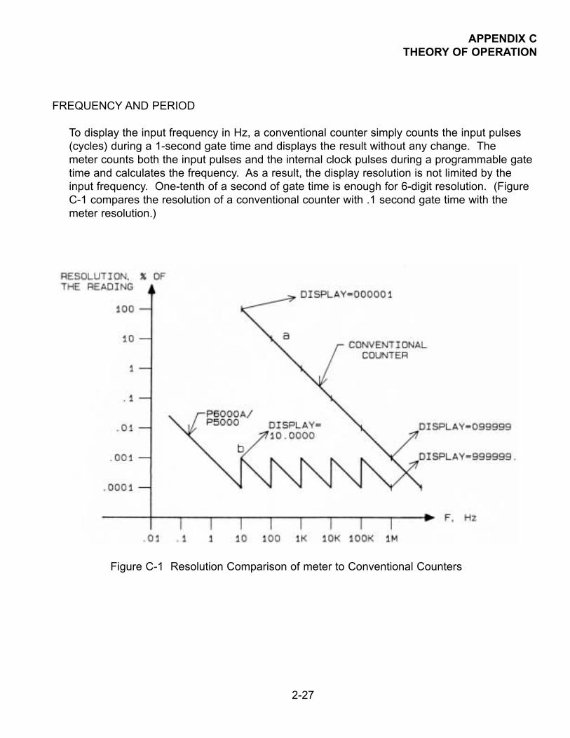
APPENDIX CTHEORY OF OPERATION
FREQUENCY AND PERIOD
To display the input frequency in Hz, a conventional counter simply counts the input pulses(cycles) during a 1-second gate time and displays the result without any change. Themeter counts both the input pulses and the internal clock pulses during a programmable gatetime and calculates the frequency. As a result, the display resolution is not limited by theinput frequency. One-tenth of a second of gate time is enough for 6-digit resolution. (FigureC-1 compares the resolution of a conventional counter with .1 second gate time with themeter resolution.)
Figure C-1 Resolution Comparison of meter to Conventional Counters
2-27
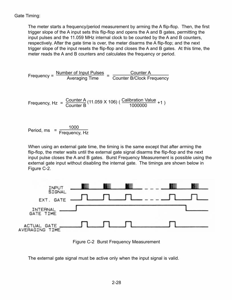
Gate Timing:
The meter starts a frequency/period measurement by arming the A flip-flop. Then, the firsttrigger slope of the A input sets this flip-flop and opens the A and B gates, permitting the input pulses and the 11.059 MHz internal clock to be counted by the A and B counters,respectively. After the gate time is over, the meter disarms the A flip-flop; and the next trigger slope of the input resets the flip-flop and closes the A and B gates. At this time, themeter reads the A and B counters and calculates the frequency or period.
Frequency =Number of Input Pulses
=Counter A
Averaging Time Counter B/Clock Frequency
Frequency, Hz =Counter A (11.059 X 10⁶) ( Calibration Value
+1 )Counter B 1000000
Period, ms =1000
Frequency, Hz
When using an external gate time, the timing is the same except that after arming the flip-flop, the meter waits until the external gate signal disarms the flip-flop and the nextinput pulse closes the A and B gates. Burst Frequency Measurement is possible using theexternal gate input without disabling the internal gate. The timings are shown below in Figure C-2.
Figure C-2 Burst Frequency Measurement
The external gate signal must be active only when the input signal is valid.
2-28
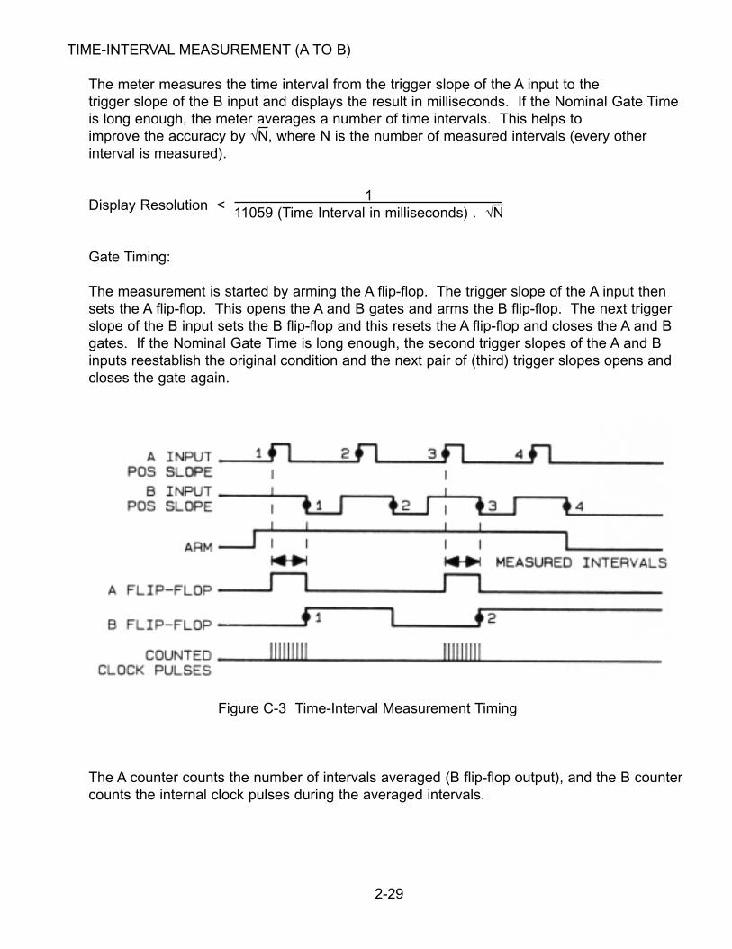
TIME-INTERVAL MEASUREMENT (A TO B)
The meter measures the time interval from the trigger slope of the A input to thetrigger slope of the B input and displays the result in milliseconds. If the Nominal Gate Timeis long enough, the meter averages a number of time intervals. This helps toimprove the accuracy by √N, where N is the number of measured intervals (every otherinterval is measured).
Display Resolution <1
11059 (Time Interval in milliseconds) . √N
Gate Timing:
The measurement is started by arming the A flip-flop. The trigger slope of the A input thensets the A flip-flop. This opens the A and B gates and arms the B flip-flop. The next triggerslope of the B input sets the B flip-flop and this resets the A flip-flop and closes the A and Bgates. If the Nominal Gate Time is long enough, the second trigger slopes of the A and Binputs reestablish the original condition and the next pair of (third) trigger slopes opens andcloses the gate again.
Figure C-3 Time-Interval Measurement Timing
The A counter counts the number of intervals averaged (B flip-flop output), and the B countercounts the internal clock pulses during the averaged intervals.
2-29
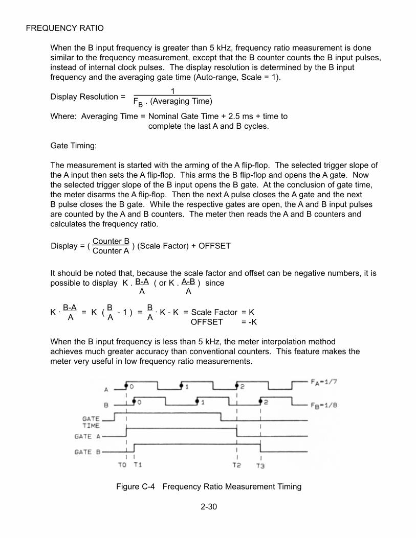
FREQUENCY RATIO
When the B input frequency is greater than 5 kHz, frequency ratio measurement is donesimilar to the frequency measurement, except that the B counter counts the B input pulses,instead of internal clock pulses. The display resolution is determined by the B inputfrequency and the averaging gate time (Auto-range, Scale = 1).
Display Resolution =1
FB . (Averaging Time)
Where: Averaging Time = Nominal Gate Time + 2.5 ms + time tocomplete the last A and B cycles.
Gate Timing:
The measurement is started with the arming of the A flip-flop. The selected trigger slope ofthe A input then sets the A flip-flop. This arms the B flip-flop and opens the A gate. Now the selected trigger slope of the B input opens the B gate. At the conclusion of gate time,the meter disarms the A flip-flop. Then the next A pulse closes the A gate and the nextB pulse closes the B gate. While the respective gates are open, the A and B input pulses are counted by the A and B counters. The meter then reads the A and B counters andcalculates the frequency ratio.
Display = ( Counter B
) (Scale Factor) + OFFSETCounter A
It should be noted that, because the scale factor and offset can be negative numbers, it ispossible to display K . B-A ( or K . A-B ) since
A A
K .B-A
= K (B
- 1 ) = B . K - K = Scale Factor = K
A A AOFFSET = -K
When the B input frequency is less than 5 kHz, the meter interpolation methodachieves much greater accuracy than conventional counters. This feature makes themeter very useful in low frequency ratio measurements.
Figure C-4 Frequency Ratio Measurement Timing
2-30
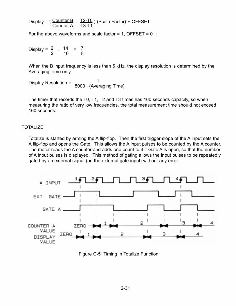
Display = ( Counter B . T2-T0 ) (Scale Factor) + OFFSETCounter A T3-T1
For the above waveforms and scale factor = 1, OFFSET = 0 :
Display = 2 . 14 = 72 16 8
When the B input frequency is less than 5 kHz, the display resolution is determined by theAveraging Time only.
Display Resolution = 1 5000 . (Averaging Time)
The timer that records the T0, T1, T2 and T3 times has 160 seconds capacity, so whenmeasuring the ratio of very low frequencies, the total measurement time should not exceed160 seconds.
TOTALIZE
Totalize is started by arming the A flip-flop. Then the first trigger slope of the A input sets theA flip-flop and opens the Gate. This allows the A input pulses to be counted by the A counter.The meter reads the A counter and adds one count to it if Gate A is open, so that the numberof A input pulses is displayed. This method of gating allows the input pulses to be repeatedlygated by an external signal (on the external gate input) without any error.
Figure C-5 Timing in Totalize Function
2-31
It should be noted that the display value and the alarm outputs status lag the input pulses by 0-25 milliseconds (calculation time) plus the communication time. This delay cannot beseen on the display but when using the alarm outputs for control purposes, it may be desired to reduce this delay as much as possible. This display update time is minimized by:
1. Disabling the parallel BCD data, if not used (sending data to the parallel BCD boardtakes about 10 milliseconds);
2. Disabling the RS-232 output by leaving RTS open or false. (The RS-232 outputtakes about 13 milliseconds at 9600 baud);
3. Using a multiplier scale factor (a divider scale factor lengthens the calculation timeabout 10 sec).
With these provisions, the display update time is reduced to 8-15 milliseconds in totalize and 20-30 milliseconds in other functions.
2-32
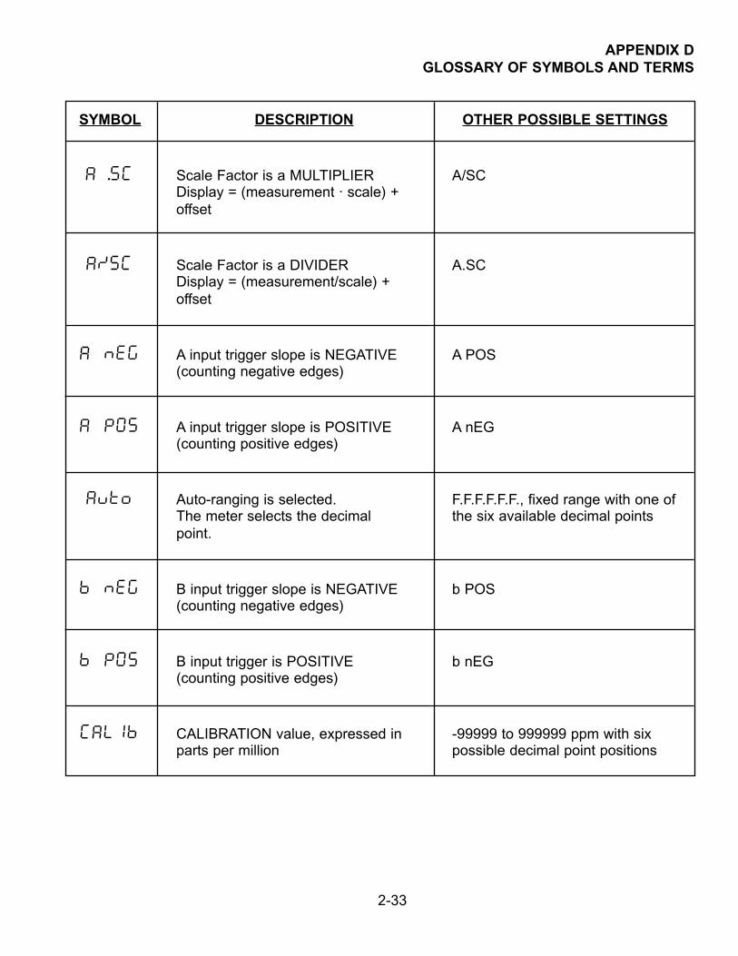
APPENDIX DGLOSSARY OF SYMBOLS AND TERMS
SYMBOL DESCRIPTION OTHER POSSIBLE SETTINGS
A .SC Scale Factor is a MULTIPLIER A/SCDisplay = (measurement · scale) +offset
A/SC Scale Factor is a DIVIDER A.SCDisplay = (measurement/scale) +offset
A nEG A input trigger slope is NEGATIVE A POS(counting negative edges)
A POS A input trigger slope is POSITIVE A nEG(counting positive edges)
Auto Auto-ranging is selected. F.F.F.F.F.F., fixed range with one ofThe meter selects the decimal the six available decimal pointspoint.
b nEG B input trigger slope is NEGATIVE b POS(counting negative edges)
b POS B input trigger is POSITIVE b nEG(counting positive edges)
CALIb CALIBRATION value, expressed in -99999 to 999999 ppm with sixparts per million possible decimal point positions
2-33
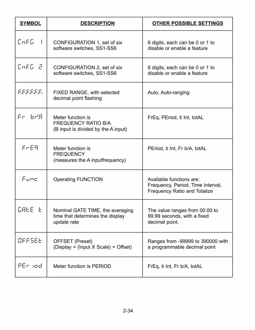
SYMBOL DESCRIPTION OTHER POSSIBLE SETTINGS
CnFG 1 CONFIGURATION 1, set of six 6 digits, each can be 0 or 1 tosoftware switches, SS1-SS6 disable or enable a feature
CnFG 2 CONFIGURATION 2, set of six 6 digits, each can be 0 or 1 tosoftware switches, SS1-SS6 disable or enable a feature
F.F.F.F.F.F. FIXED RANGE, with selected Auto, Auto-rangingdecimal point flashing
Fr b/a Meter function is FrEq, PEriod, ti Int, totALFREQUENCY RATIO B/A(B input is divided by the A input)
fre9 Meter function is PEriod, ti Int, Fr b/A, totALFREQUENCY(measures the A inputfrequency)
func Operating FUNCTION Available functions are:Frequency, Period, Time Interval,Frequency Ratio and Totalize
gate t Nominal GATE TIME, the averaging The value ranges from 00.00 totime that determines the display 99.99 seconds, with a fixedupdate rate decimal point.
Offset OFFSET (Preset) Ranges from -99999 to 390000 with (Display = (Input X Scale) + Offset) a programmable decimal point
Period Meter function is PERIOD FrEq, ti Int, Fr b/A, totAL
2-34
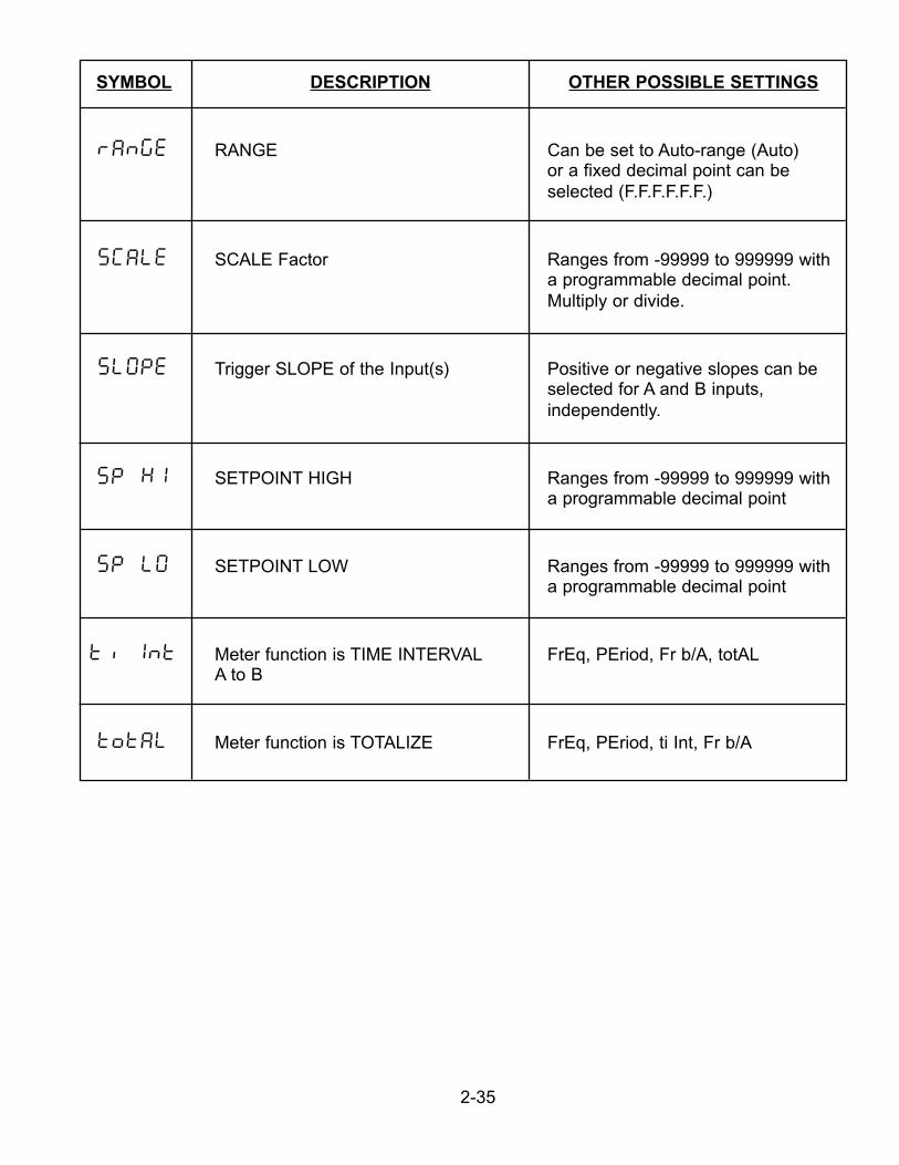
SYMBOL DESCRIPTION OTHER POSSIBLE SETTINGS
range RANGE Can be set to Auto-range (Auto)or a fixed decimal point can beselected (F.F.F.F.F.F.)
sCale SCALE Factor Ranges from -99999 to 999999 witha programmable decimal point.Multiply or divide.
SLOPE Trigger SLOPE of the Input(s) Positive or negative slopes can beselected for A and B inputs,independently.
SP HI SETPOINT HIGH Ranges from -99999 to 999999 witha programmable decimal point
SP LO SETPOINT LOW Ranges from -99999 to 999999 witha programmable decimal point
Ti Int Meter function is TIME INTERVAL FrEq, PEriod, Fr b/A, totALA to B
totAL Meter function is TOTALIZE FrEq, PEriod, ti Int, Fr b/A
2-35
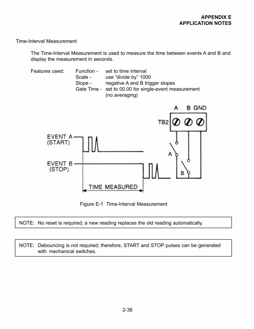
APPENDIX EAPPLICATION NOTES
Time-Interval Measurement
The Time-Interval Measurement is used to measure the time between events A and B anddisplay the measurement in seconds.
Features used: Function - set to time intervalScale - use “divide by” 1000Slope - negative A and B trigger slopesGate Time - set to 00.00 for single-event measurement
(no averaging)
Figure E-1 Time-Interval Measurement
2-36
NOTE: No reset is required; a new reading replaces the old reading automatically.
NOTE: Debouncing is not required; therefore, START and STOP pulses can be generated with mechanical switches.
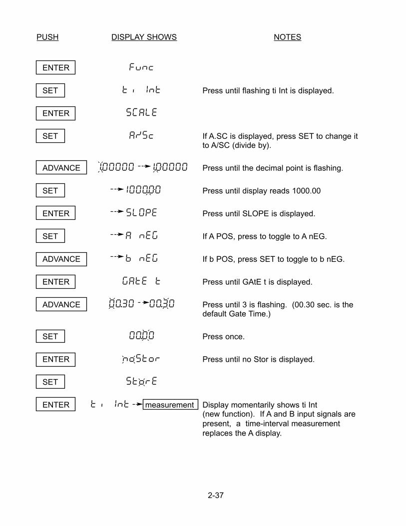
PUSH DISPLAY SHOWS NOTES
ENTER func
SET ti Int Press until flashing ti Int is displayed.
ENTER sCale
SET a/sc If A.SC is displayed, press SET to change it to A/SC (divide by).
ADVANCE 1.00000 1.00000 Press until the decimal point is flashing.
SET 1000.00 Press until display reads 1000.00
ENTER slOpe Press until SLOPE is displayed.
SET a neg If A POS, press to toggle to A nEG.
ADVANCE b neg If b POS, press SET to toggle to b nEG.
ENTER gate t Press until GAtE t is displayed.
ADVANCE 00.30 00.30 Press until 3 is flashing. (00.30 sec. is thedefault Gate Time.)
SET 00.00 Press once.
ENTER nostor Press until no Stor is displayed.
SET store
ENTER ti Int measurement Display momentarily shows ti Int(new function). If A and B input signals arepresent, a time-interval measurementreplaces the A display.
2-37
` ````
``
` ``` ` ```
` ```
` ```
`
``
` ```
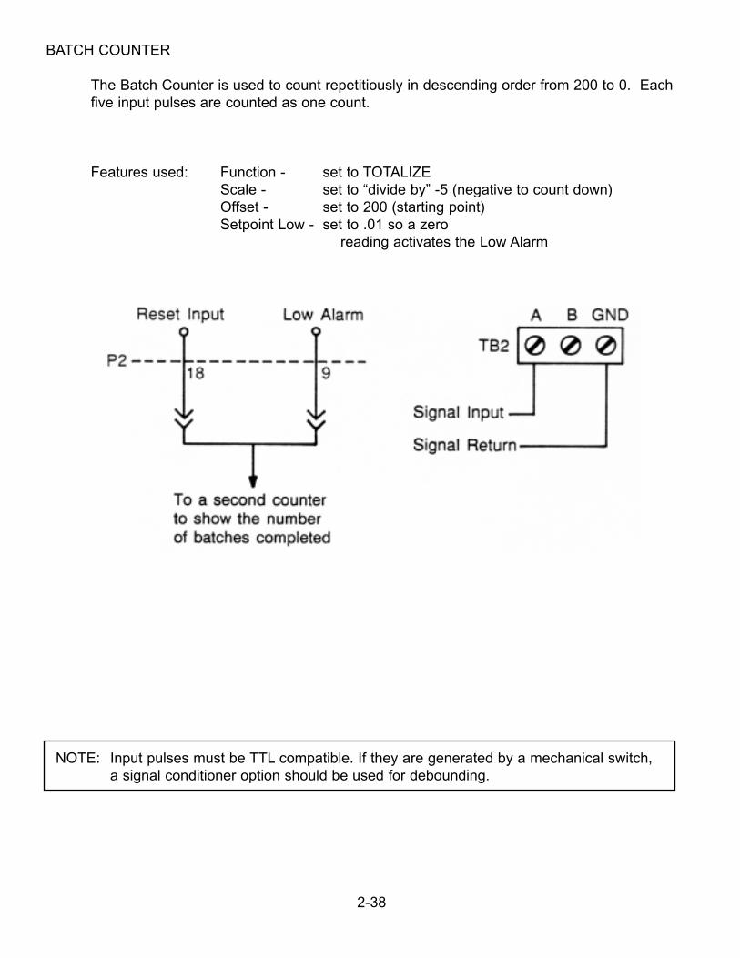
BATCH COUNTER
The Batch Counter is used to count repetitiously in descending order from 200 to 0. Eachfive input pulses are counted as one count.
Features used: Function - set to TOTALIZEScale - set to “divide by” -5 (negative to count down)Offset - set to 200 (starting point)Setpoint Low - set to .01 so a zero
reading activates the Low Alarm
2-38
NOTE: Input pulses must be TTL compatible. If they are generated by a mechanical switch, a signal conditioner option should be used for debounding.
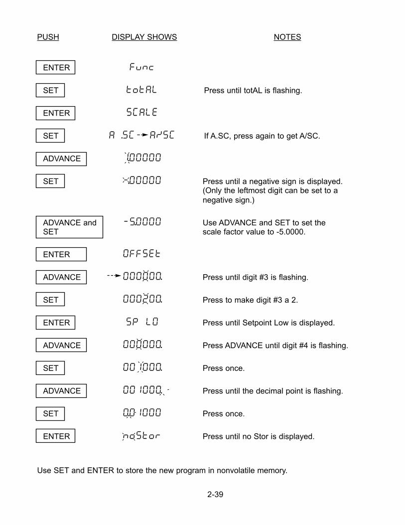
PUSH DISPLAY SHOWS NOTES
ENTER func
SET total Press until totAL is flashing.
ENTER SCALE
SET a .sC a/sC If A.SC, press again to get A/SC.
ADVANCE 1.00000
SET -.00000 Press until a negative sign is displayed. (Only the leftmost digit can be set to anegative sign.)
ADVANCE and -5.0000 Use ADVANCE and SET to set theSET scale factor value to -5.0000.
ENTER OFFSET
ADVANCE 000000. Press until digit #3 is flashing.
SET 000200. Press to make digit #3 a 2.
ENTER SP LO Press until Setpoint Low is displayed.
ADVANCE 000000. Press ADVANCE until digit #4 is flashing.
SET 001000. Press once.
ADVANCE 001000. Press until the decimal point is flashing.
SET 0.0100O Press once.
ENTER NoSTor Press until no Stor is displayed.
Use SET and ENTER to store the new program in nonvolatile memory.
2-39
` ```
`
``
` ```
` ```
`
``
` ```
` ```
` ```
` `
``
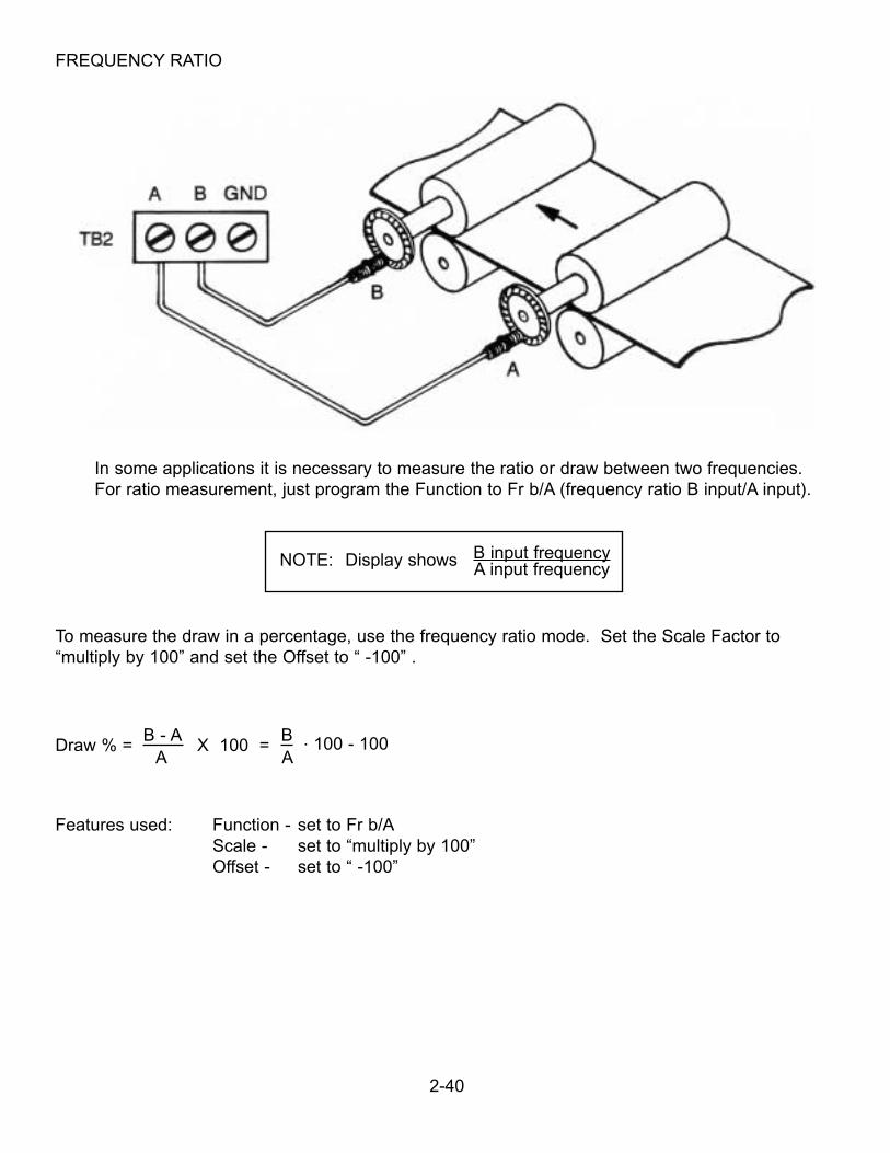
FREQUENCY RATIO
In some applications it is necessary to measure the ratio or draw between two frequencies.For ratio measurement, just program the Function to Fr b/A (frequency ratio B input/A input).
To measure the draw in a percentage, use the frequency ratio mode. Set the Scale Factor to“multiply by 100” and set the Offset to “ -100” .
Draw % = B - A
X 100 =B . 100 - 100
A A
Features used: Function - set to Fr b/AScale - set to “multiply by 100”Offset - set to “ -100”
2-40
NOTE: Display shows B input frequencyA input frequency
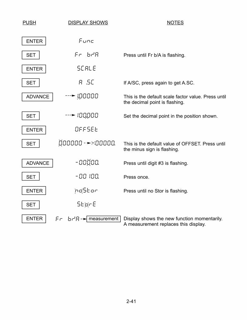
PUSH DISPLAY SHOWS NOTES
ENTER func
SET fr b/a Press until Fr b/A is flashing.
ENTER SCALE
SET A .SC If A/SC, press again to get A.SC.
ADVANCE 1.00000 This is the default scale factor value. Press untilthe decimal point is flashing.
SET 100.000 Set the decimal point in the position shown.
ENTER OFFSET
SET 000000 -00000. This is the default value of OFFSET. Press untilthe minus sign is flashing.
ADVANCE -00000. Press until digit #3 is flashing.
SET -00100. Press once.
ENTER noStor Press until no Stor is flashing.
SET StorE
ENTER Fr b/a measurement Display shows the new function momentarily. A measurement replaces this display.
2-41
` ```
`
``
`
``
` ```
` `
``
` ```
` ```
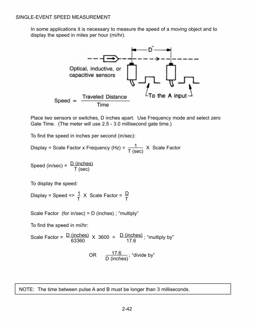
SINGLE-EVENT SPEED MEASUREMENT
In some applications it is necessary to measure the speed of a moving object and to display the speed in miles per hour (mi/hr).
Place two sensors or switches, D inches apart. Use Frequency mode and select zero Gate Time. (The meter will use 2.5 - 3.0 millisecond gate time.)
To find the speed in inches per second (in/sec):
Display = Scale Factor x Frequency (Hz) = 1 X Scale FactorT (sec)
Speed (in/sec) = D (inches)T (sec)
To display the speed:
Display = Speed => 1 X Scale Factor = DT T
Scale Factor (for in/sec) = D (inches) ; “multiply”
To find the speed in mi/hr:
Scale Factor = D (inches) X 3600 = D (inches) ; “multiply by”63360 17.6
OR 17.6 ; “divide by”D (inches)
2-42
NOTE: The time between pulse A and B must be longer than 3 milliseconds.
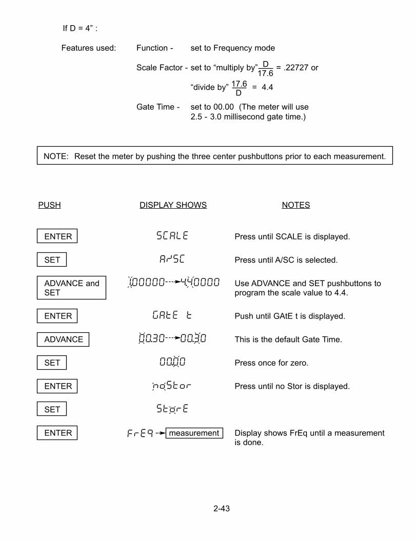
If D = 4” :
Features used: Function - set to Frequency mode
Scale Factor - set to “multiply by” D = .22727 or 17.6
“divide by” 17.6 = 4.4D
Gate Time - set to 00.00 (The meter will use 2.5 - 3.0 millisecond gate time.)
PUSH DISPLAY SHOWS NOTES
ENTER SCALE Press until SCALE is displayed.
SET A/SC Press until A/SC is selected.
ADVANCE and 1.00000 4.40000 Use ADVANCE and SET pushbuttons toSET program the scale value to 4.4.
ENTER GATE T Push until GAtE t is displayed.
ADVANCE 00.30 00.30 This is the default Gate Time.
SET 00.00 Press once for zero.
ENTER noStor Press until no Stor is displayed.
SET StorE
ENTER FrE9 measurement Display shows FrEq until a measurement is done.
2-43
NOTE: Reset the meter by pushing the three center pushbuttons prior to each measurement.
` ``` ` ```
` ```
` ```
` ```
` ``` ` ```
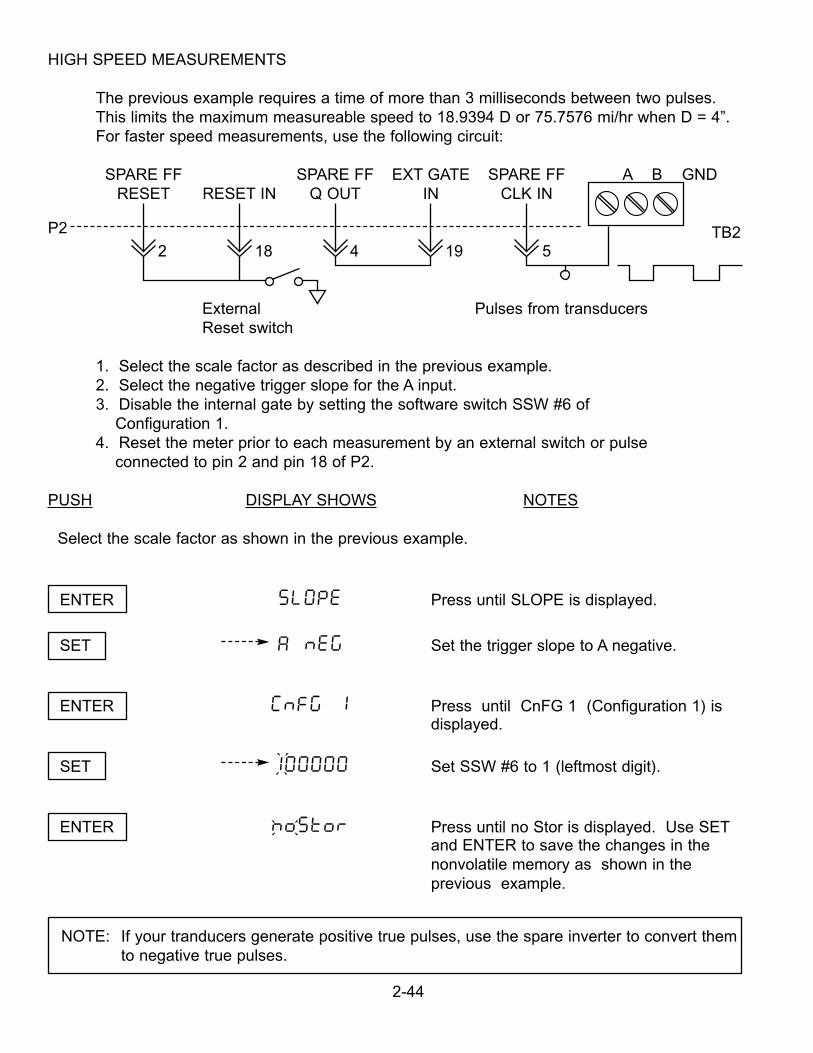
HIGH SPEED MEASUREMENTS
The previous example requires a time of more than 3 milliseconds between two pulses. This limits the maximum measureable speed to 18.9394 D or 75.7576 mi/hr when D = 4”. For faster speed measurements, use the following circuit:
SPARE FF SPARE FF EXT GATE SPARE FF A B GNDRESET RESET IN Q OUT IN CLK IN
P2
2 18 4 19 5
External Pulses from transducers Reset switch
1. Select the scale factor as described in the previous example.2. Select the negative trigger slope for the A input.3. Disable the internal gate by setting the software switch SSW #6 of
Configuration 1.4. Reset the meter prior to each measurement by an external switch or pulse
connected to pin 2 and pin 18 of P2.
PUSH DISPLAY SHOWS NOTES
Select the scale factor as shown in the previous example.
ENTER SLOPE Press until SLOPE is displayed.
SET A nEG Set the trigger slope to A negative.
ENTER CNFG 1 Press until CnFG 1 (Configuration 1) is displayed.
SET 100000 Set SSW #6 to 1 (leftmost digit).
ENTER NoStor Press until no Stor is displayed. Use SETand ENTER to save the changes in thenonvolatile memory as shown in the previous example.
2-44
NOTE: If your tranducers generate positive true pulses, use the spare inverter to convert themto negative true pulses.
` ```
` ```
TB2
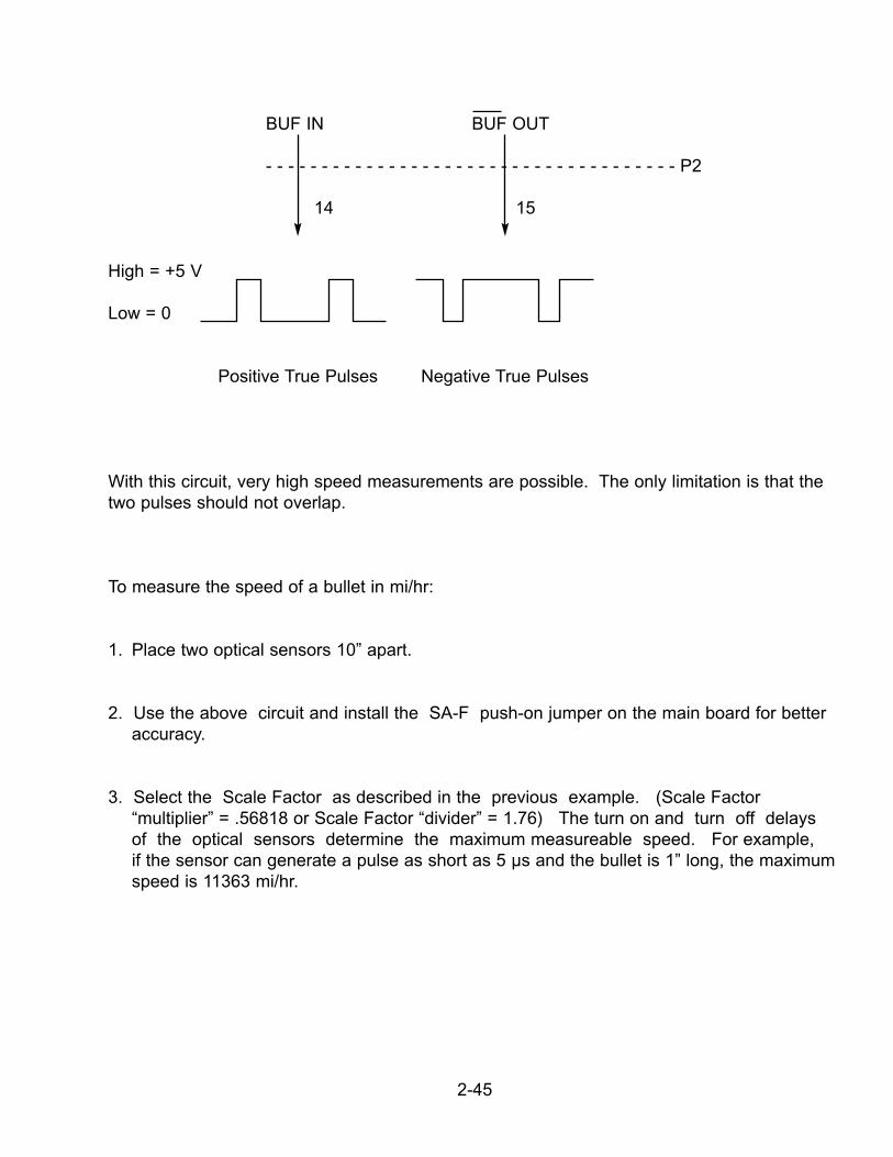
BUF IN BUF OUT
- - - - - - - - - - - - - - - - - - - - - - - - - - - - - - - - - - - - - P2
14 15
High = +5 V
Low = 0
Positive True Pulses Negative True Pulses
With this circuit, very high speed measurements are possible. The only limitation is that thetwo pulses should not overlap.
To measure the speed of a bullet in mi/hr:
1. Place two optical sensors 10” apart.
2. Use the above circuit and install the SA-F push-on jumper on the main board for betteraccuracy.
3. Select the Scale Factor as described in the previous example. (Scale Factor“multiplier” = .56818 or Scale Factor “divider” = 1.76) The turn on and turn off delays of the optical sensors determine the maximum measureable speed. For example, if the sensor can generate a pulse as short as 5 µs and the bullet is 1” long, the maximumspeed is 11363 mi/hr.
2-45
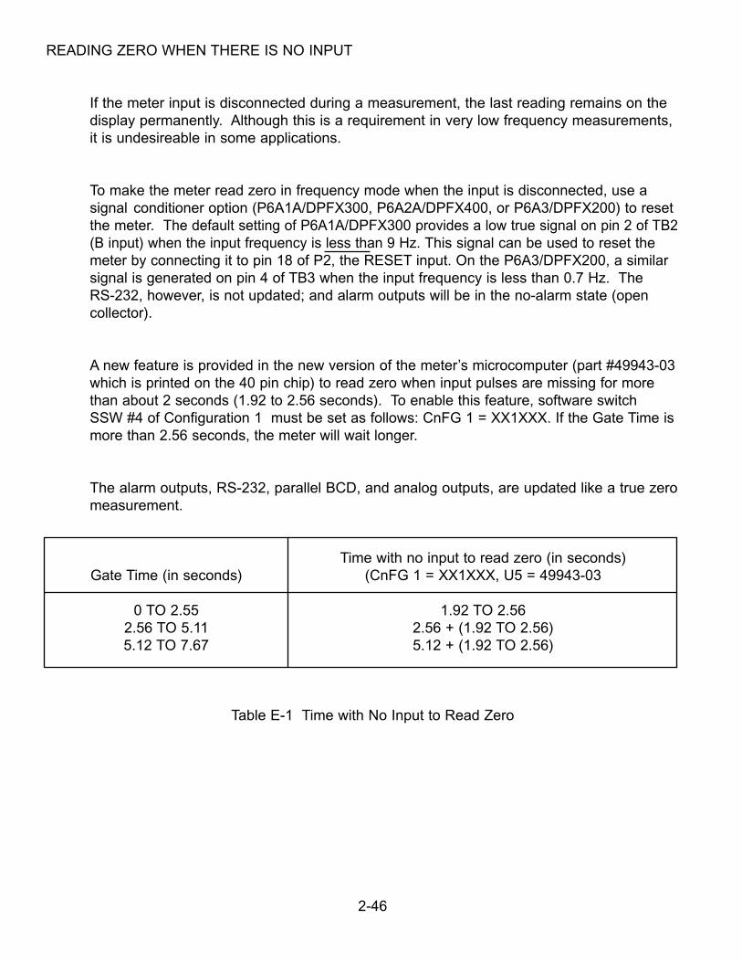
READING ZERO WHEN THERE IS NO INPUT
If the meter input is disconnected during a measurement, the last reading remains on thedisplay permanently. Although this is a requirement in very low frequency measurements, it is undesireable in some applications.
To make the meter read zero in frequency mode when the input is disconnected, use a signal conditioner option (P6A1A/DPFX300, P6A2A/DPFX400, or P6A3/DPFX200) to reset the meter. The default setting of P6A1A/DPFX300 provides a low true signal on pin 2 of TB2 (B input) when the input frequency is less than 9 Hz. This signal can be used to reset the meter by connecting it to pin 18 of P2, the RESET input. On the P6A3/DPFX200, a similarsignal is generated on pin 4 of TB3 when the input frequency is less than 0.7 Hz. The RS-232, however, is not updated; and alarm outputs will be in the no-alarm state (opencollector).
A new feature is provided in the new version of the meter’s microcomputer (part #49943-03which is printed on the 40 pin chip) to read zero when input pulses are missing for morethan about 2 seconds (1.92 to 2.56 seconds). To enable this feature, software switch SSW #4 of Configuration 1 must be set as follows: CnFG 1 = XX1XXX. If the Gate Time ismore than 2.56 seconds, the meter will wait longer.
The alarm outputs, RS-232, parallel BCD, and analog outputs, are updated like a true zeromeasurement.
Time with no input to read zero (in seconds)Gate Time (in seconds) (CnFG 1 = XX1XXX, U5 = 49943-03
0 TO 2.55 1.92 TO 2.562.56 TO 5.11 2.56 + (1.92 TO 2.56)5.12 TO 7.67 5.12 + (1.92 TO 2.56)
Table E-1 Time with No Input to Read Zero
2-46
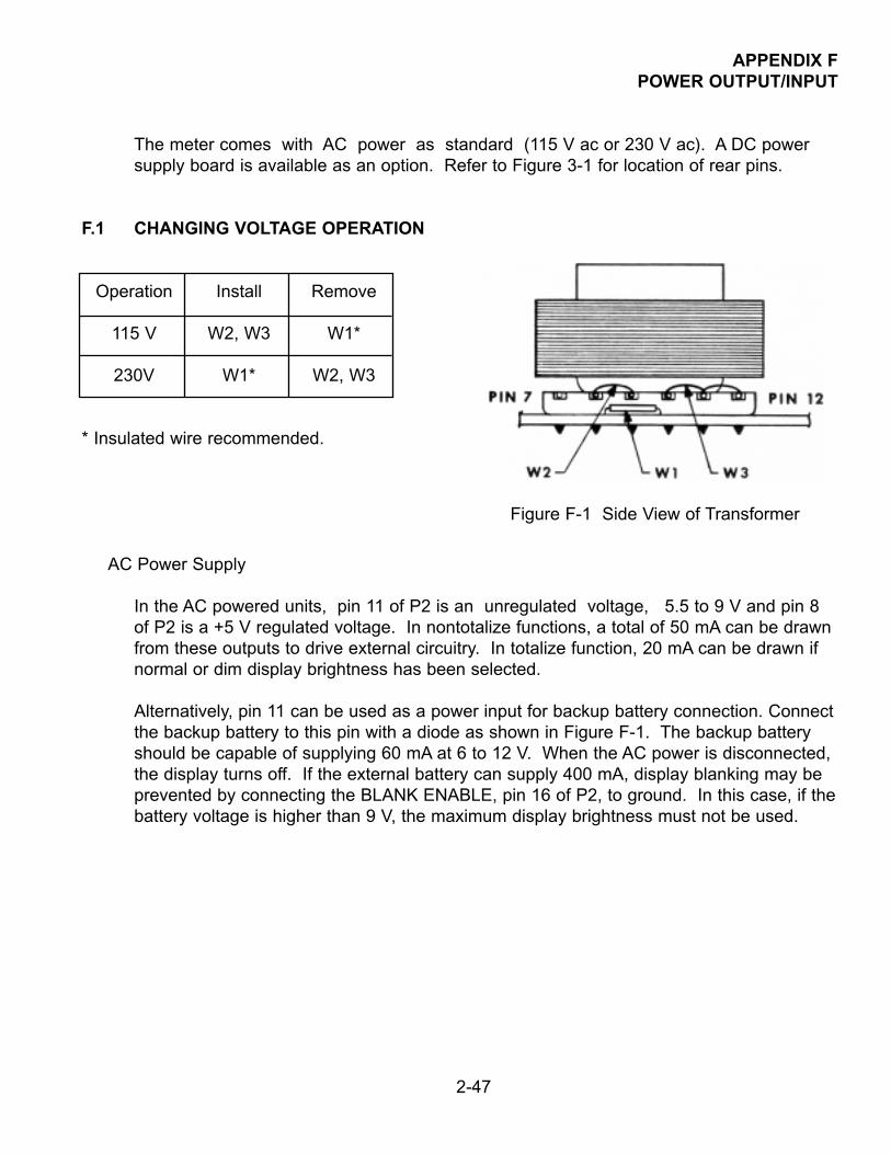
APPENDIX FPOWER OUTPUT/INPUT
The meter comes with AC power as standard (115 V ac or 230 V ac). A DC power supply board is available as an option. Refer to Figure 3-1 for location of rear pins.
F.1 CHANGING VOLTAGE OPERATION
Operation Install Remove
115 V W2, W3 W1*
230V W1* W2, W3
* Insulated wire recommended.
AC Power Supply
In the AC powered units, pin 11 of P2 is an unregulated voltage, 5.5 to 9 V and pin 8of P2 is a +5 V regulated voltage. In nontotalize functions, a total of 50 mA can be drawnfrom these outputs to drive external circuitry. In totalize function, 20 mA can be drawn ifnormal or dim display brightness has been selected.
Alternatively, pin 11 can be used as a power input for backup battery connection. Connect the backup battery to this pin with a diode as shown in Figure F-1. The backup batteryshould be capable of supplying 60 mA at 6 to 12 V. When the AC power is disconnected,the display turns off. If the external battery can supply 400 mA, display blanking may beprevented by connecting the BLANK ENABLE, pin 16 of P2, to ground. In this case, if thebattery voltage is higher than 9 V, the maximum display brightness must not be used.
2-47
Figure F-1 Side View of Transformer
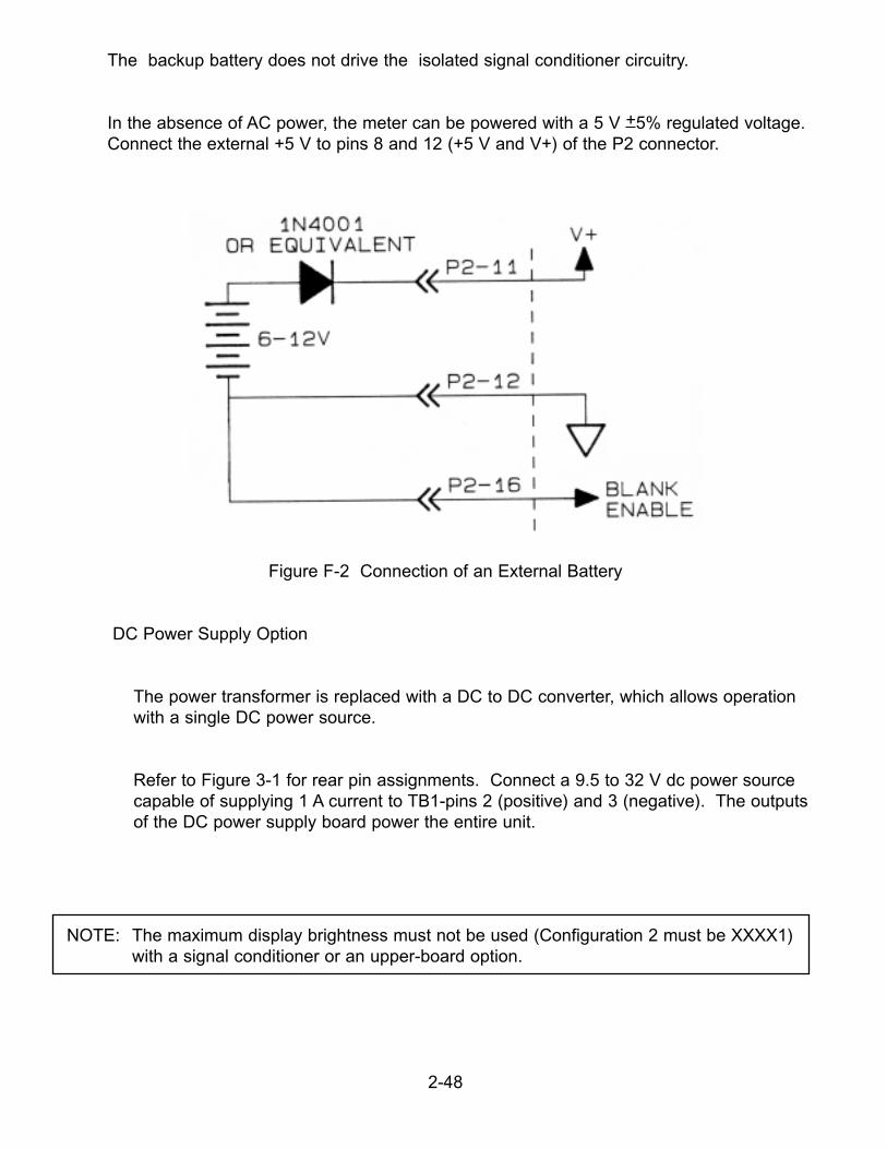
The backup battery does not drive the isolated signal conditioner circuitry.
In the absence of AC power, the meter can be powered with a 5 V +5% regulated voltage.Connect the external +5 V to pins 8 and 12 (+5 V and V+) of the P2 connector.
Figure F-2 Connection of an External Battery
DC Power Supply Option
The power transformer is replaced with a DC to DC converter, which allows operation with a single DC power source.
Refer to Figure 3-1 for rear pin assignments. Connect a 9.5 to 32 V dc power sourcecapable of supplying 1 A current to TB1-pins 2 (positive) and 3 (negative). The outputs of the DC power supply board power the entire unit.
2-48
NOTE: The maximum display brightness must not be used (Configuration 2 must be XXXX1)with a signal conditioner or an upper-board option.

NOTES
2-49

Warranty/DisclaimerNEWPORT Electronics, Inc. warrants this unit to be free of defects in materials and workmanship for a period of one(1) year from the date of purchase. In addition to NEWPORT’s standard warranty period, NEWPORT Electronics willextend the warranty period for one (1) additional year if the warranty card enclosed with each instrument is returnedto NEWPORT.
If the unit should malfunction, it must be returned to the factory for evaluation. NEWPORT’s Customer ServiceDepartment will issue an Authorized Return (AR) number immediately upon phone or written request. Uponexamination by NEWPORT, if the unit is found to be defective it will be repaired or replaced at no charge.NEWPORT’s WARRANTY does not apply to defects resulting from any action of the purchaser, including but notlimited to mishandling, improper interfacing, operation outside of design limits, improper repair, or unauthorizedmodification. This WARRANTY is VOID if the unit shows evidence of having been tampered with or shows evidenceof being damaged as a result of excessive corrosion; or current, heat, moisture or vibration; improper specification;misapplication; misuse or other operating conditions outside of NEWPORT’s control. Components which wear are notwarranted, including but not limited to contact points, fuses, and triacs.
NEWPORT is pleased to offer suggestions on the use of its various products. However, NEWPORT neitherassumes responsibility for any omissions or errors nor assumes liability for any damages that result from theuse of its products in accordance with information provided by NEWPORT, either verbal or written. NEWPORTwarrants only that the parts manufactured by it will be as specified and free of defects. NEWPORT MAKES NOOTHER WARRANTIES OR REPRESENTATIONS OF ANY KIND WHATSOEVER, EXPRESSED OR IMPLIED,EXCEPT THAT OF TITLE, AND ALL IMPLIED WARRANTIES INCLUDING ANY WARRANTY OFMERCHANTABILITY AND FITNESS FOR A PARTICULAR PURPOSE ARE HEREBY DISCLAIMED. LIMITATIONOF LIABILITY: The remedies of purchaser set forth herein are exclusive and the total liability of NEWPORTwith respect to this order, whether based on contract, warranty, negligence, indemnification, strict liability orotherwise, shall not exceed the purchase price of the component upon which liability is based. In no eventshall NEWPORT be liable for consequential, incidental or special damages.
CONDITIONS: Equipment sold by NEWPORT is not intended to be used, nor shall it be used: (1) as a “BasicComponent” under 10 CFR 21 (NRC), used in or with any nuclear installation or activity; or (2) in medical applicationsor used on humans. Should any Product(s) be used in or with any nuclear installation or activity, medical application,or used on humans, or misused in any way, NEWPORT assumes no responsibility as set forth in our basicWARRANTY / DISCLAIMER language, and additionally purchaser will indemnify NEWPORT and hold NEWPORTharmless from any liability or damage whatsoever arising out of the use of the Product(s) in such a manner.
Direct all warranty and repair requests/inquiries to the NEWPORT Customer ServiceDepartment. BEFORE RETURNING ANY PRODUCT(S) TO NEWPORT, PURCHASER MUSTOBTAIN AN AUTHORIZED RETURN (AR) NUMBER FROM NEWPORT’S CUSTOMERSERVICE DEPARTMENT (IN ORDER TO AVOID PROCESSING DELAYS). The assigned ARnumber should then be marked on the outside of the return package and on anycorrespondence.The purchaser is responsible for shipping charges, freight, insurance and proper packaging toprevent breakage in transit.
FOR WARRANTY RETURNS, pleasehave the following information availableBEFORE contacting NEWPORT:1. P.O. number under which the product
was PURCHASED,2. Model and serial number of the product
under warranty, and3. Repair instructions and/or specific
problems relative to the product.
FOR NON-WARRANTY REPAIRS, consultNEWPORT for current repair charges. Have thefollowing information available BEFOREcontacting NEWPORT:1. P.O. number to cover the COST of
the repair,2. Model and serial number of product, and3. Repair instructions and/or specific problems
relative to the product.
NEWPORT’s policy is to make running changes, not model changes, whenever an improvement is possible. Thisaffords our customers the latest in technology and engineering.NEWPORT is a registered trademark of NEWPORT Electronics, Inc.© Copyright 2003 NEWPORT Electronics, Inc. All rights reserved. This document may not be copied,photocopied, reproduced, translated, or reduced to any electronic medium or machine-readable form, in whole or inpart, without prior written consent of NEWPORT Electronics, Inc.
Return Requests/Inquiries

M911/N/0103 11364ML-01 Rev. J
For immediate technical or application assistance please call:
Newport Electronics, Inc.2229 South Yale Street • Santa Ana, CA • 92704 • U.S.A.
TEL: (714) 540-4914 • FAX: (203) 968-7311Toll Free: 1-800-639-7678 • www.newportUS.com • e-mail:[email protected]
ISO 9001 Certified
Newport Technologies, Inc.976 Bergar • Laval (Quebec) • H7L 5A1 • Canada
TEL: (514) 335-3183 • FAX: (514) 856-6886Toll Free: 1-800-639-7678 • www.newport.ca • e-mail:[email protected]
Newport Electronics, Ltd.One Omega Drive • River Bend Technology Centre
Northbank, Irlam • Manchester M44 5BD • United KingdomTel: +44 161 777 6611 • FAX: +44 161 777 6622
Toll Free: 0800 488 488 • www.newportuk.co.uk • e-mail:[email protected]
Newport Electronics B.V.Postbus 8034 • 1180 LA Amstelveen • The Netherlands
TEL: +31 20 3472121 • FAX: +31 20 6434643Toll Free: 0800 0993344 • www.newport.nl • e-mail: [email protected]
Newport Electronics spol s.r.o.Frystatska 184, 733 01 Karviná • Czech RepublicTEL: +420 59 6311899 • FAX: +420 59 6311114
Toll Free: 0800-1-66342 • www.newport.cz • e-mail: [email protected]
Newport Electronics GmbHDaimlerstrasse 26 • D-75392 Deckenpfronn • Germany
TEL: 49 7056 9398-0 • FAX: 49 7056 9398-29Toll Free: 0800 / 6397678 • www.newport.de • e-mail: [email protected]
Newport Electronique S.A.R.L.11, rue Jacques Cartier • 78280 Guyancourt • France
TEL: +33 1 61 37 29 00 • FAX: +33 1 30 57 54 27Toll Free: 0800 466 342 • www.newport.fr • e-mail: [email protected]
Mexico and Latin AmericaFAX: 001 (203) 359-7807
En Español: 001 (203) 359-7803
®