p4m890-m7 se setup manual -...
TRANSCRIPT

P4M890-M7 SE Setup Manual
FCC Information and Copyright
This equipment has been tes ted and found to comply with the limits of a Class B digital device, pursuant to Part 15 of the FCC Rules . These limits are designed to provide reasonable protec tion against harmful interference in a residential installation. This equipment generates , uses and can radiate radio frequency energy and, if not ins talled and used in accordance with the instructions , may cause harmful interference to radio communications . There is no guarantee that interference will not occur in a particular ins tallation.
The vendor makes no representations or warranties with respec t to the contents here and specially disclaims any implied warranties of merchantability or fitness for any purpose. Further the vendor reserves the right to revise this publication and to make changes to the contents here without obligation to notify any party beforehand.
Duplication of this publication, in part or in whole, is not allowed without first obtaining the vendor’s approval in writing.
The content of this user’s manual is subject to be changed without notice and we will not be responsible for any mis takes found in this user’s manual. All the brand and produc t names are trademarks of their respec tive companies .

Table of Contents
Chapter 1: Introduction .............................................3
1.1 Before You Start................................................................... 3 1.2 Package Checklist................................................................ 3 1.3 Motherboard Features.......................................................... 4 1.4 Rear Panel Connectors.......................................................... 5 1.5 Motherboard Layout ............................................................ 6
Chapter 2: Hardware Installation..............................7 2.1 Installing Central Processing Unit (CPU) ................................ 7 2.2 FAN Headers........................................................................ 9 2.3 Installing System Memory.....................................................10 2.4 Connectors and Slots ............................................................11
Chapter 3: Headers & Jumpers Setup......................13 3.1 How to Setup Jumpers..........................................................13 3.2 Detail Settings.....................................................................13
Chapter 4: Useful Help ..............................................18 4.1 Driver Installation Note .......................................................18 4.2 AWARD BIOS Beep Code......................................................19 4.3 Extra Information................................................................19 4.4 Troubleshooting...................................................................21
Chapter 5: WarpSpeeder™ .......................................22 5.1 Introduction........................................................................22 5.2 System Requirement............................................................22 5.3 Installation .........................................................................23 5.4 WarpSpeeder™ ....................................................................24
Appendencies: SPEC In Other Language ................30 German................................................................................................30 France..................................................................................................32 Italian..................................................................................................34 Spanish ................................................................................................36 Portuguese ...........................................................................................38 Polish...................................................................................................40 Russian ................................................................................................42 Arabic..................................................................................................44 Japanese ..............................................................................................46

P4M890-M7 SE
3
CHAPTER 1: INTRODUCTION 1.1 BEFORE YOU START
Thank you for choosing our product. Before you start installing the motherboard, please make sure you follow the instructions below:
Prepare a dry and stable working environment with sufficient lighting.
Always disconnect the computer from power outlet before operation.
Before you take the motherboard out from anti-static bag, ground yourself properly by touching any safely grounded appliance, or use grounded wrist strap to remove the static charge.
Avoid touching the components on motherboard or the rear side of the board unless necessary. Hold the board on the edge, do not try to bend or flex the board.
Do not leave any unfastened small parts inside the case after installation. Loose parts will cause short circuits which may damage the equipment.
Keep the computer from dangerous area, such as heat source, humid air and water.
1.2 PACKAGE CHECKLIST HDD Cable X 1 User’s Manual X 1 Fully Setup Driver CD X 1
Rear I/O Panel for ATX Case X 1 FDD Cable X 1 (optional) Serial ATA Cable X 1 (optional) USB 2.0 Cable X1 (optional) S/PDIF Cable X 1 (optional) Serial ATA Power Cable X 1 (optional)

Motherboard Manual
4
1.3 MOTHERBOARD FEATURES SPEC
CPU
LGA 775
Intel Core2Duo/ Pentium 4 / Pentium D /
Celeron D processor up to 3.8 GHz
*It is recommended to use processors
with 95W power consumption.
Supports Hyper Transport/ Execute Disable
Bit/ Enhanced Intel S peedStep®/ Intel
Extended Memory 64 technology
FSB 533 / 800 / 1066 MHz
Chipset VIA P4M890
VIA VT8237A
Graphic Integrated i n UniChrome Pro Chipset Max Shared Video Memory is 64 MB
Super I/O
ITE IT8712F
Provides the most commonly used
legacy Super I/O functionality.
Low Pin Count Interface
Environment Control initiatives,
H/W Monitor
Fan Speed Controller
ITE's "Smart Guardian" function
Main
Memory
DIMM Slots x 2
Supports DDR2 533
Each DIMM supports
256/512MB/1GB/2GB DDR2
Max Memory Capicity 4GB
Single Channel Mode DDR2 memory module
Registered DIMM and ECC DIMM is not
supported
IDE Integrated IDE Controller Ultra DMA 33~133 Bus Master Mode
supports PIO Mode 0~4,
SATA Integrated Seri al ATA Controller Data transfer rates up to 1.5 Gb/s.
SATA Version 1.0 specification compliant.
LAN PHY Realtek RTL 8201CL PHY 10 / 100 Mb/s auto negotiation
Half / Full duplex capability
Sound
Codec ALC861VD
5.1 channels audio out
High-Defi nition Audio s upport
PCI Express x 16 slot x1 Supports PCI express x16 expansion cards
PCI Express x 1 slot x1 Supports PCI express x1 expansion cards Slots
PCI slot x2 Supports PCI expansion cards
Floppy connector x1 Each connector supports 2 Floppy drives
IDE Connector x2 Each connector supports 2 IDE device
SATA Connector x2 Each connector supports 1 SATA devices
Front Panel Connector x1 Supports front panel facilities
Front Audio Connector x1 Supports front panel audio function
On Board
Connector
CD-in Connector x1 Supports CD audio-in function
P4M890-M7 SE
5
SPEC
S/PDIF out connector x1 Supports di gital audio out function
CPU Fan header x1 CPU Fan power s upply (with Smart Fan
function)
System Fan header x1 System Fan Power supply
Clear CMOS header x1 Restore CMOS data to factory default
USB connector x2 Each connector supports 2 front panel USB
ports
Power Connector (24pin) x1 Connects to Power supply
Power Connector (4pin) x1 Connects to Power supply
Back Panel
I/O
PS/2 Keyboard x1
PS/2 Mouse x1
Serial Port x1
Printer Port x1
VGA Port x1
LAN port x1
USB Port x4
Audio Jack x3
Connects to PS/2 Keyboard
Connects to PS/2 Mouse
Provide RS-232 Serial connection
Connects to vari ous types of device
Connects to monitor.
Connects to RJ-45 ethernet cable
Connects to USB devices
Provide Audio-In/Out and microphone
connection
Board Size 190 mm (W) x 244 mm (L) Micro ATX form Factor
OS
Support Windows 2000 / XP
Biostar Reserves the right to add or remove
support for any OS with or without notice.
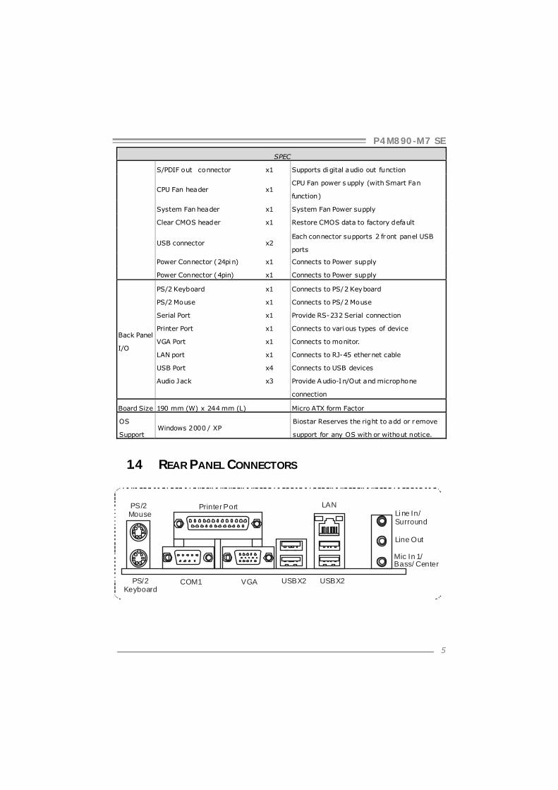
1.4 REAR PANEL CONNECTORS
PS/2 Mouse
PS/2 Keyboard
USBX2USBX2
LAN
COM1 VGA
Printer PortLi ne In/Surround
Line Out
Mic In 1/Bass/ Center

Motherboard Manual
6
1.5 MOTHERBOARD LAYOUT
SuperI/O
DIM
M1
DIM
M2
FDD1
PCI-EX1_1
PCI-EX16
PCI1
PCI2
JPANEL1
JUSB2
JUSB3
JATXPWR1
JCFAN1
JATXPWR2
JSATA1
JSATA2
Codec
JCDIN1
JSFAN1
BAT1
BIOS
VIA VT8237A
LGA775
CPU1
P4M890
JAUDIOF1
JKBMS1
JUSB1
JUSBLAN1
CO
M1
JCO
M1
JVG
A1
JAUDIO1
JSPDIF_OUT1
IDE
1
JCMOS1
LANID
E2
JUSBV2
JUSBV1
JPR
NT
1
Not e: represents the 1■ st pin.
P4M890-M7 SE
7
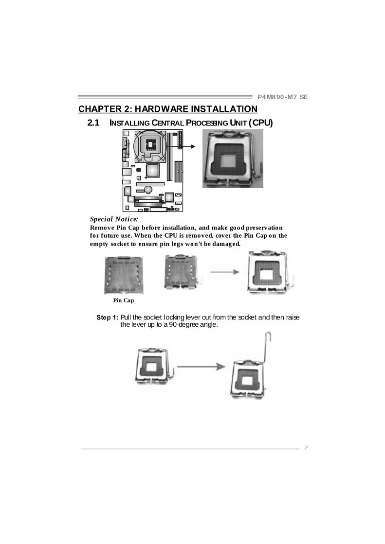
CHAPTER 2: HARDWARE INSTALLATION 2.1 INSTALLING CENTRAL PROCESSING UNIT (CPU)
Special Notice: Remove Pin Cap before installation, and make good preservation for future use. When the CPU is removed, cover the Pin Cap on the empty socket to ensure pin legs won’t be damaged.
Pin Cap
Step 1: Pull the socket locking lever out from the socket and then raise
the lever up to a 90-degree angle.
Motherboard Manual
8
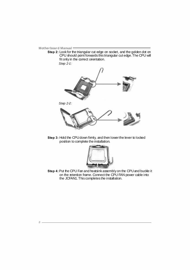
Step 2: Look for the triangular cut edge on socket, and the golden dot on CPU should point forwards this triangular cut edge. The CPU will fit only in the correct orientation.
Step 2-1:
Step 2-2:
Step 3: Hold the CPU down firmly, and then lower the lever to locked position to complete the installation.
Step 4: Put the CPU Fan and heatsink assembly on the CPU and buckle it
on the retention frame. Connect the CPU FAN power cable into the JCFAN1. This completes the installation.

P4M890-M7 SE
9
2.2 FAN HEADERS These fan headers support cooling-fans built in the computer. The fan cable and connector may be different according to the fan manufacturer. Connect the fan cable to the connector while matching the black wire to pin#1. JCFAN1: CPU Fan Header
Pin
Assignment 1 Ground 2 +12V 3 FAN RPM rate
sense
14JCFAN1
4 Smart Fan Control
JSFAN1: System Fan Header
Pin
Assignment 1 Ground 2 +12V
13
JSFAN1
3 FAN RPM rate sense
Note: The JSFAN1 support 3-pi n head connec tor. When connecti ng with wires onto connec tors, please note that the red wire is the positi ve and should be connected to pin#2, and the black wire is Ground and should be connected to GND.

Motherboard Manual
10
2.3 INSTALLING SYSTEM MEMORY A. Memory Modules
DIM
M1
DIM
M2
1. Unlock a DIMM slot by pressing the retaining clips outward. Align a
DIMM on the slot such that the notch on the DIMM matches the break on the Slot.
2. Insert the DIMM vertically and firmly into the slot until the retaining
chip snap back in place and the DIMM is properly seated.
B. Memory Capacity
DIMM Socket Location
DDR Module Total Memory Size
DIMM1 256MB/512MB/1GB/2GB DIMM2 256MB/512MB/1GB/2GB
Max is 4GB.
P4M890-M7 SE
11
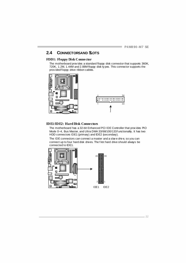
2.4 CONNECTORS AND SLOTS
FDD1: Floppy Disk Connector The motherboard prov ides a standard floppy disk connector that supports 360K, 720K, 1.2M, 1.44M and 2.88M floppy disk ty pes. This connector supports the prov ided f loppy drive ribbon cables.
34
331
2
IDE1/IDE2: Hard Disk Connectors The motherboard has a 32-bit Enhanced PCI IDE Controller that prov ides PIO Mode 0~4, Bus Master, and Ultra DMA 33/66/100/133 f unctionality. It has two HDD connectors IDE1 (primary) and IDE2 (secondary). The IDE connectors can connect a master and a slav e driv e, so you can connect up to four hard disk drives. The f irst hard drive should always be connected to IDE1.
IDE2IDE1
2 1
3940
Motherboard Manual
12
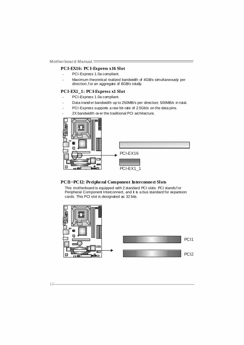
PCI-EX16: PCI-Express x16 Slot - PCI-Express 1.0a compliant. - Maximum theoretical realized bandwidth of 4GB/s simultaneously per
direction, f or an aggregate of 8GB/s totally.
PCI-EX1_1: PCI-Express x1 Slot - PCI-Express 1.0a compliant. - Data transf er bandwidth up to 250MB/s per direction; 500MB/s in total. - PCI-Express supports a raw bit-rate of 2.5Gb/s on the data pins. - 2X bandwidth ov er the traditional PCI architecture.
PCI-EX16
PCI-EX1_1
PCI1~PCI2: Peripheral Component Interconnect Slots This motherboard is equipped with 2 standard PCI slots. PCI stands f or Peripheral Component Interconnect, and it is a bus standard for expansion cards. This PCI slot is designated as 32 bits.
PCI1
PCI2

P4M890-M7 SE
13
CHAPTER 3: HEADERS & JUMPERS SETUP 3.1 HOW TO SETUP JUMPERS
The illustration shows how to set up jumpers. When the jumper cap is placed on pins, the jumper is “close”, if not, that means the jumper is “open”.
Pin opened Pin closed Pin1-2 closed
3.2 DETAIL SETTINGS JPANEL1: Front Panel Header
This 16-pin connector includes Power-on, Reset, HDD LED, Power LED, Sleep button and speaker connection. It allows user to connect the PC case’s f ront panel switch functions.
1 816
SLPPWR_LED
On/Off
RSTHLED
SPK
+ +
+9
-
-
Pin Assignment Function Pin Assignment Function 1 +5V 9 Sleep control 2 N/A 10 Ground
Sleep button
3 N/A 11 N/A N/A 4 Speaker
Speaker Connector
12 Power LED (+) 5 HDD LED (+) 13 Power LED (+) 6 HDD LED (-)
Hard drive LED 14 Power LED (-)
Power LED
7 Ground 15 Power button 8 Reset control
Reset button 16 Ground
Power-on button

Motherboard Manual
14
ATX Power Source Connector: JATXPWR1 JATXPWR1 allows user to connect 24-pin power connector on the ATX power supply.
1
12
13
24
Pin Assignment Pin Assignment 13 +3.3V 1 +3.3V 14 -12V 2 +3.3V 15 Ground 3 Ground 16 PS_ON 4 +5V 17 Ground 5 Ground 18 Ground 6 +5V 19 Ground 7 Ground 20 NC 8 PW_OK 21 +5V 9 Standby Voltage+5V 22 +5V 10 +12V 23 +5V 11 +12V 24 Ground 12 +3.3V
JATXPWR2: ATX Power Source Connector By connecting this connector, it will provide +12V to CPU power circuit.
Pin
Assignment
1 +12V 2 +12V 3 Ground
1
2 3
4
4 Ground

P4M890-M7 SE
15
JUSB2/JUSB3: Headers for USB 2.0 Ports at Front Panel This header allows user to connect additional USB cable on the PC f ront panel, and also can be connected with internal USB devices, like USB card reader.
Pin
Assignment
1 +5V (fused) 2 +5V (fused) 3 USB- 4 USB- 5 USB+ 6 USB+ 7 Ground 8 Ground 9 Key
1
2
9
10 JUSB2
JUSB3
10 NC
JUSBV1/JUSBV2: Power Source Headers for USB Ports Pin 1-2 Close:
JUSBV1: +5V for USB ports at JUSB1/JUSBLAN1. JUSBV2: +5V for USB ports at f ront panel (JUSB2/JUSB3).
Pin 2-3 Close: JUSBV1: USB ports at JUSB1/JUSBLAN1 are powered by +5V standby
v oltage. JUSBV2: USB ports at front panel (JUSB2/JUSB3) are powered by +5V
standby v oltage.
31
Pin 1-2 close
1 3
JUSBV1
JUSBV2
1 3
31
Pin 2-3 close
Note: In order to support this function “Power-On system vi a USB device,” “JUSBV1/ JUSBV2” jumper cap should be placed on Pin 2-3 indi viduall y.

Motherboard Manual
16
JAUDIO F1: Front Panel Audio Header This header allows user to connect the front audio output cable with the PC f ront panel. It will disable the output on back panel audio connectors.
Pin Assignment 1 Mic Left in 2 Ground 3 Mic Right in 4 GPIO 5 Right line in 6 Jack Sense 7 Front Sense 8 Key 9 Left line in
10 Jack Sense
1 9
2 10
JCDIN1: CD-RO M Audio-in Connector This connector allows user to connect the audio source f rom the v ariaty dev ices, like CD-ROM, DVD-ROM, PCI sound card, PCI TV turner card etc.
Pin
Assignment
1 Left Channel Input 2 Ground 3 Ground
14
4 Right Channel Input
JSPDIF_O UT1: Digital Audio-out Connector This connector allows user to connect the PCI bracket SPDIF output header.
Pin
Assignment
1 +5V 2 SPDIF_OUT
13
3 Ground

P4M890-M7 SE
17
JCMO S1: Clear CMOS Header By placing the jumper on pin2-3, it allows user to restore the BIOS saf e setting and the CMOS data, please carefully f ollow the procedures to avoid damaging the motherboard.
1 3
Pin 1-2 Close: Normal Operation (default).
1 3
1 3
Pin 2-3 Close: Clear CMOS data.
※ Clear CMOS Procedures: 1. Remov e AC power line. 2. Set the jumper to “Pin 2-3 close”. 3. Wait f or f ive seconds. 4. Set the jumper to “Pin 1-2 close”. 5. Power on the AC. 6. Reset y our desired password or clear the CMOS data.
JSATA1~JSATA2: Serial ATA Connectors The motherboard has a PCI to SATA Controller with 2 channels SATA interf ace, it satisfies the SATA 1.0 spec and with transfer rate of 1.5Gb/s.
Pin
Assignment
1 Ground 2 TX+ 3 TX- 4 Ground 5 RX- 6 RX+
1 4 7
JSATA1
JSATA2
147
7 Ground
Motherboard Manual
18
CHAPTER 4: USEFUL HELP 4.1 DRIVER INSTALLATION NOTE
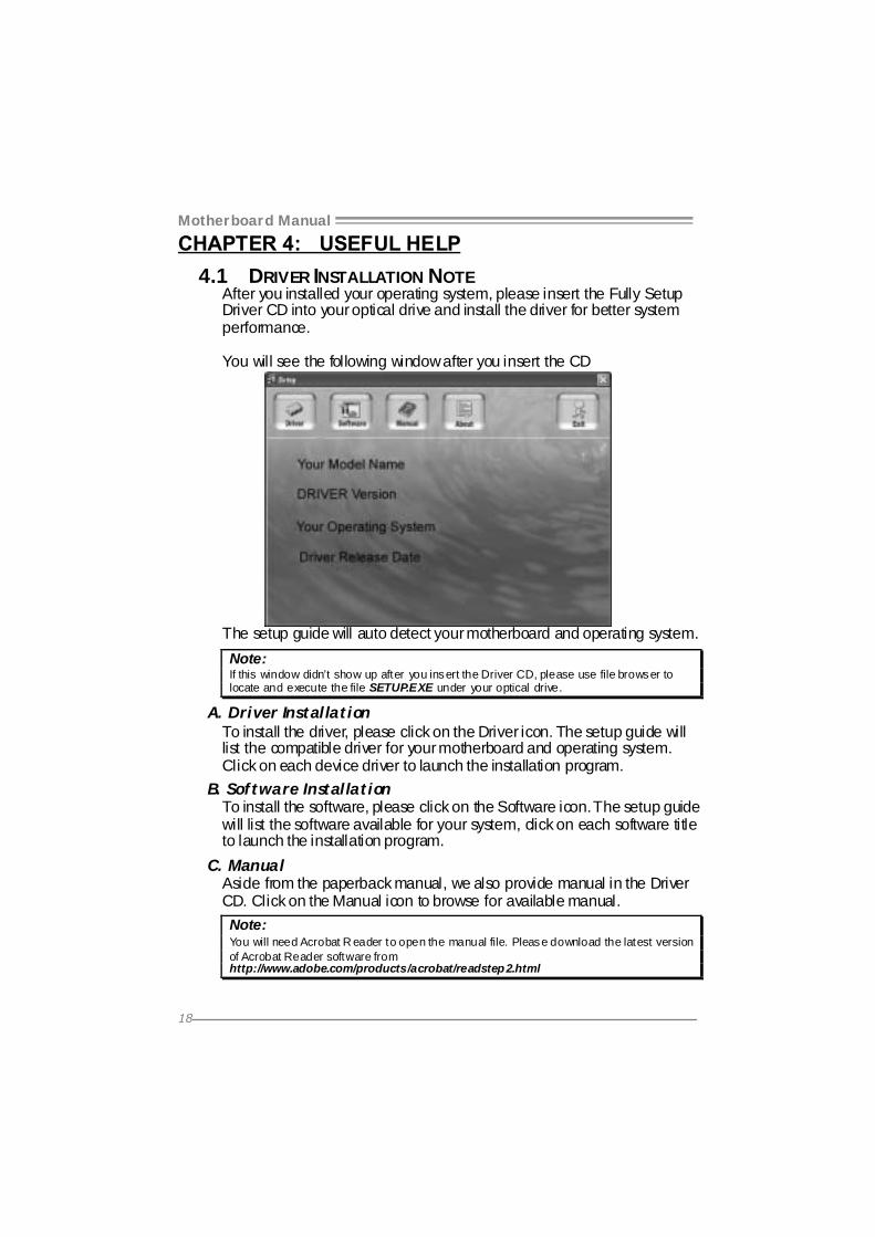
After you installed your operating system, please insert the Fully Setup Driver CD into your optical drive and install the driver for better system performance. You will see the following window after you insert the CD
The setup guide will auto detect your motherboard and operating system. Note: If this window didn’t show up after you insert the Driver CD, please use file browser to locate and execute the file SETUP.EXE under your optical drive.
A. Driver Installation To install the driver, please click on the Driver icon. The setup guide will list the compatible driver for your motherboard and operating system. Click on each device driver to launch the installation program.
B. Software Installation To install the software, please click on the Software icon. The setup guide will list the software available for your system, click on each software title to launch the installation program.
C. Manual Aside from the paperback manual, we also provide manual in the Driver CD. Click on the Manual icon to browse for available manual. Note: You will need Acrobat R eader to open the manual file. Please download the latest version of Acrobat Reader software from http://www.adobe.com/products/acrobat/readstep 2.html
P4M890-M7 SE
19
4.2 AWARD BIOS BEEP CODE Beep Sound Meaning
One long beep followed by two short beeps
Video card not found or v ideo card memory bad
High-low siren sound CPU overheated System will shut down automatically
One Short beep when system boot-up No error found during POST Long beeps every other second No DRAM detected or install
4.3 EXTRA INFORMATION A. BIOS Update
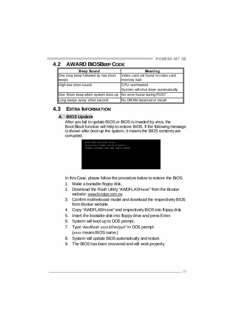
After you fail to update BIOS or BIOS is invaded by virus, the Boot-Block function will help to restore BIOS. If the following message is shown after boot-up the system, it means the BIOS contents are corrupted.
In this Case, please follow the procedure below to restore the BIOS: 1. Make a bootable floppy disk. 2. Download the Flash Utility “AWDFLASH.exe” from the Biostar
website: www.biostar.com.tw 3. Confirm motherboard model and download the respectively BIOS
from Biostar website. 4. Copy “AWDFLASH.exe” and respectively BIOS into floppy disk. 5. Insert the bootable disk into floppy drive and press Enter. 6. System will boot-up to DOS prompt. 7. Type “Awdflash xxxx.bf/sn/py/r” in DOS prompt.
(xxxx means BIOS name.) 8. System will update BIOS automatically and restart. 9. The BIOS has been recovered and will work properly.

Motherboard Manual
20
B. CPU Overheated If the system shutdown automatically after power on system for seconds, that means the CPU protection function has been activated. When the CPU is over heated, the motherboard will shutdown automatically to avoid a damage of the CPU, and the system may not power on again. In this case, please double check:
1. The CPU cooler surface is placed evenly with the CPU surface. 2. CPU fan is rotated normally. 3. CPU fan speed is fulfilling with the CPU speed.
After confirmed, please follow steps below to relief the CPU protection function.
1. Remove the power cord from power supply for seconds. 2. Wait for seconds. 3. Plug in the power cord and boot up the system.
Or you can:
1. Clear the CMOS data. (See “Close CMOS Header: JCMOS1” section)
2. Wait for seconds. 3. Power on the system again.

P4M890-M7 SE
21
4.4 TROUBLESHOOTING Probable Solution
1. No power to the system at all Power light don’t illuminate, f an inside power supply does not turn on.
2. Indicator light on key board does not turn on.
1. Make sure power cable is securely plugged in.
2. Replace cable. 3. Contact technical support.
System inoperativ e. Keyboard lights are on, power indicator lights are lit, and hard driv e is spinning.
Using even pressure on both ends of the DIMM, press down firmly until the module snaps into place.
System does not boot from hard disk driv e, can be booted f rom optical driv e.
1. Check cable running from disk to disk controller board. Make sure both ends are securely plugged in; check the driv e type in the standard CMOS setup.
2. Backing up the hard drive is extremely important. All hard disks are capable of breaking down at any time.
System only boots f rom optical driv e. Hard disk can be read and applications can be used but booting from hard disk is impossible.
1. Back up data and applications f iles.
2. Ref ormat the hard driv e. Re-install applications and data using backup disks.
Screen message says “Invalid Conf iguration” or “CMOS Failure.”
Rev iew system’s equipment. Make surecorrect inf ormation is in setup.
Cannot boot system after installing second hard driv e.
1. Set master/slave jumpers correctly.
2. Run SETUP program and select correct driv e types. Call the drive manuf acturers f or compatibility with other drives.

Motherboard Manual
22
CHAPTER 5: WARPSPEEDER™
5.1 INTRODUCTION [WarpSpeeder™], a new powerful control utility, features three user-friendly functions including Overclock Manager, Overvoltage Manager, and Hardware Monitor. With the Overclock Manager, users can easily adjust the frequency they prefer or they can get the best CPU performance with just one click. The Overvoltage Manager, on the other hand, helps to power up CPU core voltage and Memory voltage. The cool Hardware Monitor smartly indicates the temperatures, voltage and CPU fan speed as well as the chipset information. Also, in the About panel, you can get detail descriptions about BIOS model and chipsets. In addition, the frequency status of CPU, memory, AGP and PCI along with the CPU speed are synchronically shown on our main panel. Moreover, to protect users' computer systems if the setting is not appropriate when testing and results in system fail or hang, [WarpSpeeder™] technology assures the system stability by automatically rebooting the computer and then restart to a speed that is either the original system speed or a suitable one.
5.2 SYSTEM REQUIREMENT OS Support: Windows 98 SE, Windows Me, Windows 2000, Windows XP DirectX: DirectX 8.1 or above. (The Windows XP operating system includes DirectX 8.1. If you use Windows XP, you do not need to install DirectX 8.1.)
P4M890-M7 SE
23
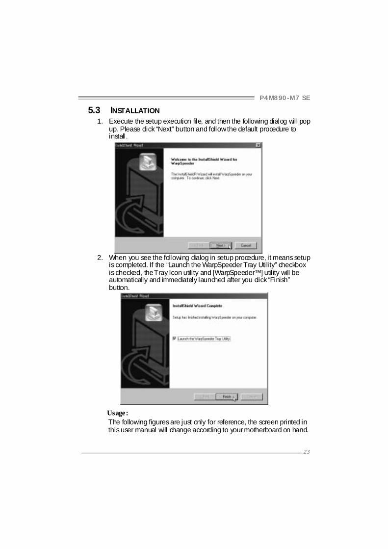
5.3 INSTALLATION 1. Execute the setup execution file, and then the following dialog will pop
up. Please click “Next” button and follow the default procedure to install.
2. When you see the following dialog in setup procedure, it means setup
is completed. If the “Launch the WarpSpeeder Tray Utility” checkbox is checked, the Tray Icon utility and [WarpSpeeder™] utility will be automatically and immediately launched after you click “Finish” button.
Usage: The following figures are just only for reference, the screen printed in this user manual will change according to your motherboard on hand.

Motherboard Manual
24
5.4 WARPSPEEDER™ 1. Tray Icon:
Whenever the Tray Icon utility is launched, it will display a little tray icon on the right side of Windows Taskbar.
This utility is responsible for conveniently invoking [WarpSpeeder™] Utility. You can use the mouse by clicking the left button in order to invoke [WarpSpeeder™] directly from the little tray icon or you can right-click the little tray icon to pop up a popup menu as following figure. The “Launch Utility” item in the popup menu has the same function as mouse left-click on tray icon and “Exit” item will close Tray Icon utility if selected.

P4M890-M7 SE
25
2. Main Panel If you click the tray icon, [WarpSpeeder™] utility will be invoked. Please refer to the following figure; the utility’s first window you will see is Main Panel. Main Panel contains features as follows:
a. Display the CPU Speed, CPU external clock, Memory clock, AGP clock, and PCI clock information.
b. Contains About, Voltage, Overclock, and Hardware Monitor Buttons for invoking respective panels.
c. With a user-friendly Status Animation, it can represent 3 overclock percentage stages:
Man walking→overclock percentage from 100% ~ 110 % Panther running→overclock percentage from 110% ~ 120% Car racing→overclock percentage from 120% ~ above

Motherboard Manual
26
3. Voltage Panel Click the Voltage button in Main Panel, the button will be highlighted and the Voltage Panel will slide out to up as the following figure. In this panel, you can decide to increase CPU core voltage and Memory voltage or not. The default setting is “No”. If you want to get the best performance of overclocking, we recommend you click the option “Yes”.
P4M890-M7 SE
27
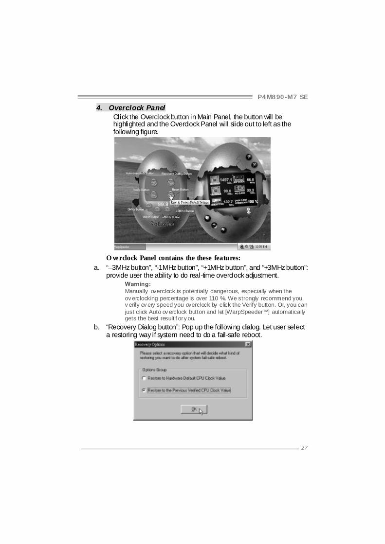
4. Overclock Panel Click the Overclock button in Main Panel, the button will be highlighted and the Overclock Panel will slide out to left as the following figure.
O verclock Panel contains the these features:
a. “–3MHz button”, “-1MHz button”, “+1MHz button”, and “+3MHz button”: provide user the ability to do real-time overclock adjustment.
Warning: Manually overclock is potentially dangerous, especially when the ov erclocking percentage is over 110 %. We strongly recommend you v erify ev ery speed you overclock by click the Verify button. Or, you can just click Auto ov erclock button and let [WarpSpeeder™] automatically gets the best result f or y ou.
b. “Recovery Dialog button”: Pop up the following dialog. Let user select a restoring way if system need to do a fail-safe reboot.

Motherboard Manual
28
c. “Auto-overclock button”: User can click this button and [WarpSpeeder™] will set the best and stable performance and frequency automatically. [WarpSpeeder™] utility will execute a series of testing until system fail. Then system will do fail-safe reboot by using Watchdog function. After reboot, the [WarpSpeeder™] utility will restore to the hardware default setting or load the verified best and stable frequency according to the Recovery Dialog’s setting.
d. “Verify button”: User can click this button and [WarpSpeeder™] will proceed a testing for current frequency. If the testing is ok, then the current frequency will be saved into system registry. If the testing fail, system will do a fail-safe rebooting. After reboot, the [WarpSpeeder™] utility will restore to the hardware default setting or load the verified best and stable frequency according to the Recovery Dialog’s setting. Note: Because the testing programs, invoked in Auto-overclock and Verify, include DirectDraw, Direct3D and DirectShow tests, the DirectX 8.1 or newer runtime library is required. And please make sure y our display card’s color depth is High color (16 bit) or True color( 24/32 bit ) that is required f or Direct3D rendering.
5. Hardware Monitor Panel Click the Hardware Monitor button in Main Panel, the button will be highlighted and the Hardware Monitor panel will slide out to left as the following figure. In this panel, you can get the real-time status information of your system. The information will be refreshed every 1 second.
P4M890-M7 SE
29
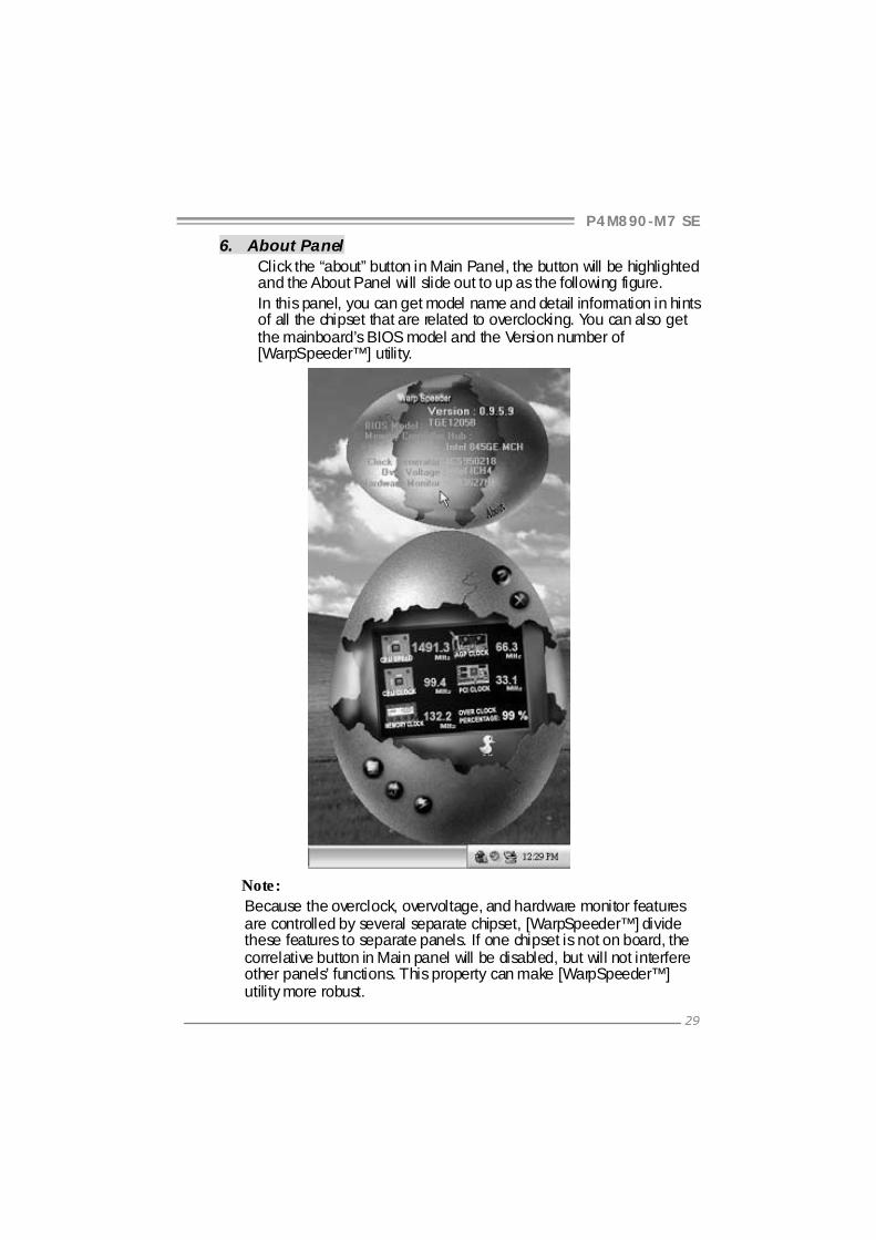
6. About Panel Click the “about” button in Main Panel, the button will be highlighted and the About Panel will slide out to up as the following figure. In this panel, you can get model name and detail information in hints of all the chipset that are related to overclocking. You can also get the mainboard’s BIOS model and the Version number of [WarpSpeeder™] utility.
Note: Because the overclock, overvoltage, and hardware monitor features are controlled by several separate chipset, [WarpSpeeder™] divide these features to separate panels. If one chipset is not on board, the correlative button in Main panel will be disabled, but will not interfere other panels’ functions. This property can make [WarpSpeeder™] utility more robust.

Motherboard Manual
30
APPENDENCIES: SPEC IN OTHER LANGUAGE GERMAN
Spezifikationen
CPU
LGA 775
Intel Core2Duo/ Pentium 4 / Pentium D
/ Celeron D Prozessoren mit bis zu 3,8
GHz
*It is recommended to use processors
with 95W power consumption.
Unterstützt Hyper-Threading / Execute Disable
Bit / Enhanced Intel SpeedStep® / Intel
Architecture-64 / Extended Memory 64
Technology
FSB 533 / 800 / 1066 MHz
Chipsatz VIA P4M890
VIA VT8237A
Grafik Integrierter UniChrome Pro Chipsatz Max. 64MB gemeinsam benutzter
Videospeicher
Super E/A
ITE 8712F
Bietet die häufi g verwendeten alten
Super E/A-Funktionen.
Low Pin Count-Schnittstelle
Umgebungskontrolle,
Hardware-Überwachung
Lüfterdrehzahl-Controller
"Smart Guardian"-Funktion von ITE
Arbeitsspeic
her
DDR2 DIMM-Steckplätze x 2
Unterstützt DDR2 533
Jeder DIMM unterstützt
256/512MB/1GB/2GB DDR2.
Max. 4GB Arbeitsspeicher
Ein-Kanal DDR2 Speichermodul
registrierte DIMMs. ECC DIMMs werden nicht
unterstützt.
IDE
Integrierter IDE-Controller
Ultra DMA 33 / 66 / 100 / 133Bus
Master-Modus
Unterstützt PIO-Modus 0~4,
SATA Integrierter Serial ATA-Controller
Datentransferrate bis zu 1.5Gb/s
Konform mit der SATA-Spezifikation Version
1.0.
LAN PHY Realtek RTL 8201CL PHY 10 / 100 Mb/s Auto-Negotiation
Halb-/ Vollduplex-Funktion
Audio-Code
c ALC861VD
Unterstützt High-Definition Audio
5.1-Kanal-Audioausgabe
PCI-Steckplatz x2
PCI Express x16 Steckplatz x1 Steckplätze
PCI Express x 1-Steckplatz x1

P4M890-M7 SE
31
Spezifikationen
Diskettenlaufwerkanschluss x1 Jeder Anschluss unterstützt 2
Diskettenlaufwerke
IDE-Anschluss x2 Jeder Anschluss unterstützt 2 IDE-Laufwerke
SATA-Anschluss x2 Jeder Anschluss unterstützt 1 SATA-Laufwerk
Fronttafelanschluss x1 Unterstützt die Fronttafelfunktionen
Front-Audioanschluss x1 Unterstützt die
Fronttafel-Audioanschlussfunktion
CD-IN-Anschluss x1 Unterstützt die CD Audio-In-Funktion
S/PDIF-Ausgangsanschluss x1 Unterstützt die di gitale Audioausgabefunktion
CPU-Lüfter-Sockel x1 CPU-Lüfterstromversorgungsanschluss (mit
Smart Fan-Funktion)
System-Lüfter-Sockel x1 System-Lüfter-Stromversorgungsanschluss
"CMOS löschen"-Sockel x1
USB-Anschluss x2 Jeder Anschluss unterstützt 2
Fronttafel-USB-Anschlüsse
Stromanschluss (24-polig) x1
Onboard-An
schluss
Stromanschluss (4-poli g) x1
Rückseiten-
E/A
PS/2-Tastatur x1
PS/2-Maus x1
Serieller Anschluss x1
Druckeranschluss x1
VGA-Anschluss x1
LAN-Anschluss x1
USB-Anschluss x4
Audioanschluss x3
Platinengrö
ße. 190 mm (B) X 244 mm (L)
OS-Unterst
ützung Windows 2K / XP
Biostar behält sich das Recht vor, ohne
Ankündigung die Unterstützung für ei n
Betriebssystem hinzuzufügen oder zu
entfernen.
Motherboard Manual
32
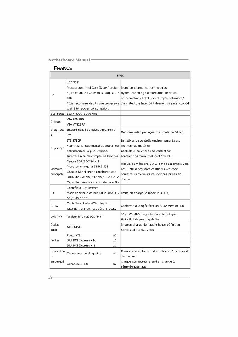
FRANCE SPEC
UC
LGA 775
Processeurs Intel Core2Duo/ Pentium
4 / Pentium D / Celeron D jusqu'à 3,8
GHz
*It is recommended to use processors
with 95W power consumption.
Prend en charge les technologies
Hyper-Threading / d'exécution de bit de
désactivation / Intel SpeedStep® optimisée/
d'architecture Intel 64 / de mémoire étendue 64
Bus frontal 533 / 800 / 1066 MHz
Chipset VIA P4M890
VIA VT8237A
Graphique
s
Integré dans l a chipset UniChrome
Pro Mémoire vidéo partagée maximale de 64 Mo
Super E/S
ITE 8712F
Fournit la fonctionnalité de Super E/S
patrimoniales la plus utilisée.
Interface à faible compte de broc hes
Initiatives de contrôle environnementales,
Moniteur de matériel
Contrôleur de vitesse de ventilateur
Fonction "Gardien i ntelligent" de l'ITE
Mémoire
principale
Fentes DDR2 DIMM x 2
Prend en charge la DDR2 533
Chaque DIMM prend en charge des
DDR2 de 256 Mo /512 Mo / 1Go / 2 Go
Capacité mémoire maximale de 4 Go
Module de mémoire DDR2 à mode à simple voie
Les DIMM à registres et DIMM avec code
correcteurs d'erreurs ne sont pas prises en
charge
IDE
Contrôleur IDE intégré
Mode principale de Bus Ultra DMA 33 /
66 / 100 / 133
Prend en charge le mode PIO 0~4,
SATA Contrôleur Serial ATA intégré :
Taux de transfert jusqu'à 1.5 Go/s. Conforme à la spécification SATA Version 1.0
LAN PHY Realtek RTL 8201CL PHY 10 / 100 Mb/s négociation automatique
Half / Full duplex capability
Codec
audio ALC861VD
Prise en c harge de l'audio haute définition
Sortie audio à 5.1 voies
Fente PCI x2
Slot PCI Express x16 x1 Fentes
Slot PCI Express x 1 x1
Connecteur de disquette x1 Chaque connector prend en charge 2 lecteurs de
disquettes
Connecteu
r
embarqué Connecteur IDE x2
Chaque connecteur prend en charge 2
périphéri ques IDE
P4M890-M7 SE
33
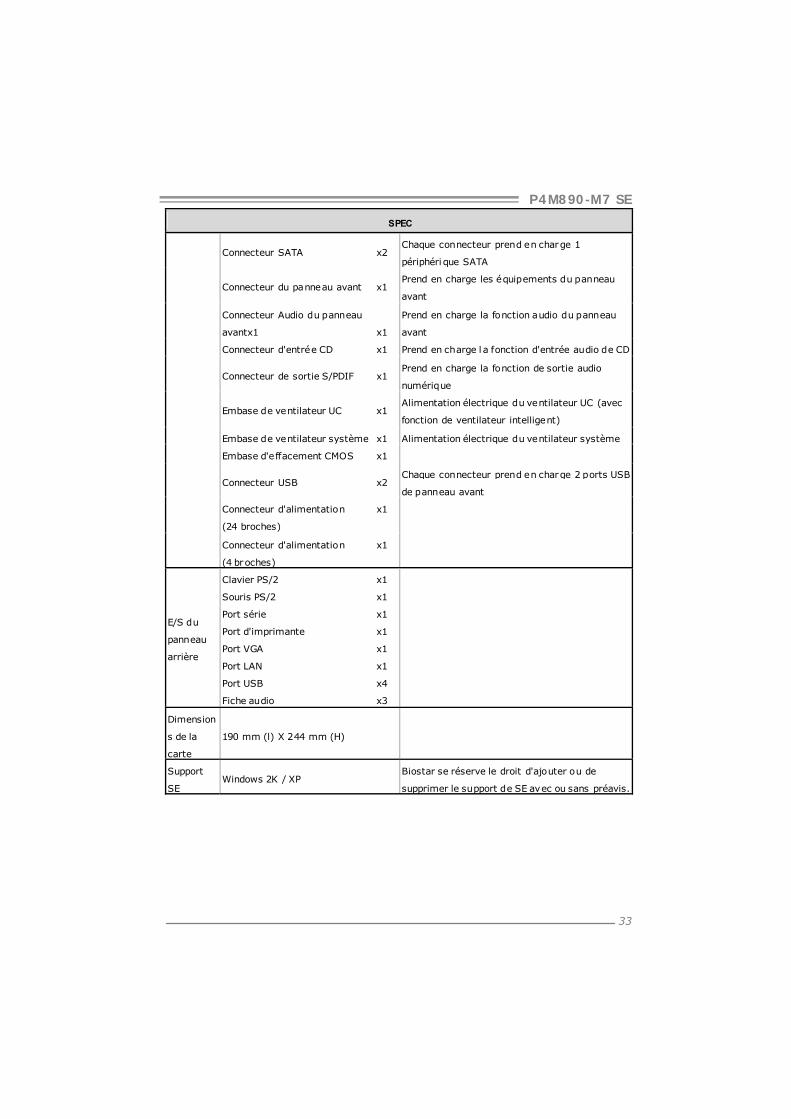
SPEC
Connecteur SATA x2 Chaque connecteur prend en charge 1
périphéri que SATA
Connecteur du panneau avant x1 Prend en charge les équipements du panneau
avant
Connecteur Audio du panneau
avantx1 x1
Prend en charge la fonction audio du panneau
avant
Connecteur d'entrée CD x1 Prend en charge l a fonction d'entrée audio de CD
Connecteur de sortie S/PDIF x1 Prend en charge la fonction de sortie audio
numérique
Embase de ventilateur UC x1 Alimentation électrique du ventilateur UC (avec
fonction de ventilateur intelligent)
Embase de ventilateur système x1 Alimentation électrique du ventilateur système
Embase d'effacement CMOS x1
Connecteur USB x2 Chaque connecteur prend en charge 2 ports USB
de panneau avant
Connecteur d'alimentation x1
(24 broches)
Connecteur d'alimentation x1
(4 broches)
E/S du
panneau
arrière
Clavier PS/2 x1
Souris PS/2 x1
Port série x1
Port d'imprimante x1
Port VGA x1
Port LAN x1
Port USB x4
Fiche audio x3
Dimension
s de la
carte
190 mm (l) X 244 mm (H)
Support
SE Windows 2K / XP
Biostar se réserve le droit d'ajouter ou de
supprimer le support de SE avec ou sans préavis.
Motherboard Manual
34
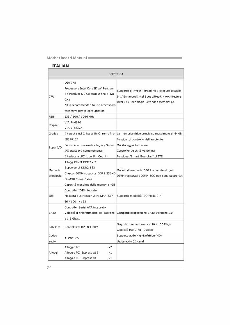
ITALIAN
SPECIFICA
CPU
LGA 775
Processore Intel Core2Duo/ Pentium
4 / Pentium D / Celeron D fino a 3.8
GHz
*It is recommended to use processors
with 95W power consumption.
Supporto di Hyper-Threading / Execute Disable
Bit / Enhanced Intel SpeedStep® / Architettura
Intel 64 / Tecnologia Extended Memory 64
FSB 533 / 800 / 1066 MHz
Chipset VIA P4M890
VIA VT8237A
Grafica Integrata nel Chipset UniChrome Pro La memoria vi deo condivisa massima è di 64MB
Super I/O
ITE 8712F
Fornisce le funzionalità legacy Super
I/O usate più comunemente.
Interfaccia LPC (Low Pin Count)
Funzioni di controllo dell’ambiente:
Monitoraggio hardware
Controller velocità ventolina
Funzione "Smart Guardi an" di ITE
Memoria
principale
Alloggi DIMM DDR2 x 2
Supporto di DDR2 533
Ciascun DIMM supporta DDR2 256MB
/512MB / 1GB / 2GB
Capacità massima della memoria 4GB
Modulo di memoria DDR2 a canale singolo
DIMM registrati e DIMM ECC non sono supportati
IDE
Controller IDE i ntegrato
Modalità Bus Master Ultra DMA 33 /
66 / 100 / 133
Supporto modalità PIO Mode 0-4
SATA
Controller Serial ATA integrato
Velocità di trasferimento dei dati fi no
a 1.5 Gb/s.
Compatibile specifiche SATA Versione 1.0.
LAN PHY Realtek RTL 8201CL PHY Negoziazione automatica 10 / 100 Mb/s
Capacità Half / Full Duplex
Codec
audio ALC861VD
Supporto audio High-Definition (HD)
Uscita audio 5.1 canali
Alloggio PCI x2
Alloggio PCI Express x16 x1 Alloggi
Alloggio PCI Express x1 x1

P4M890-M7 SE
35
SPECIFICA
Connettore floppy x1 Ciascun connettore supporta 2 unità Floppy
Connettore IDE x2 Ciascun connettore supporta 2 unità IDE
Connettore SATA x2 Ciascun connettore supporta 1 unità SATA
Connettore pannello frontale x1 Supporta i servizi del pannell o frontale
Connettore audio frontale x1 Supporta la funzione audio pannello frontale
Connettore CD-in x1 Supporta la funzione i nput audio CD
Connettore output SPDIF x1 Supporta la funzione d’output audio digitale
Collettore ventolina CPU x1 Alimentazione ventolina CPU (con funzione Smart
Fan)
Collettore ventolina sistema x1 Alimentazione ventolina di sistema
Collettore cancellazione CMOS x1
Connettore USB x2 Ciascun connettore supporta 2 porte USB
pannello frontale
Connettore alimentazione x1
(24 pin)
Connettori
su scheda
Connettore alimentazione x1
(4 pin)
I/O
pannello
posteriore
Tastiera PS/2 x1
Mouse PS/2 x1
Porta seriale x1
Porta stampante x1
Porta VGA x1
Porta LAN x1
Porta USB x4
Connettore audio x3
Dimension
i scheda
190 mm (larghezza) x 244 mm
(altezza)
Sistemi
operativi
supportati
Windows 2K / XP
Biostar si riserva il diritto di aggiungere o
rimuovere il supporto di qualsiasi sistema
operativo senza preavviso.

Motherboard Manual
36
SPANISH Especificación
CPU
LGA 775
Procesador Intel Core2Duo/ Pentium
4 / Pentium D / Celeron D hasta 3,8
GHz
*It is recommended to use processors
with 95W power consumption.
Admite Hyper-Threading / Bit de deshabilitación
de ejecución / Intel SpeedStep® Mejorado / Intel
Architecture-64 / Tecnologí a Extended Memory
64
FSB 533 / 800 / 1066 MHz
Conjunto
de chips
VIA P4M890
VIA VT8237A
Gráficos Integrados en el conjunto de chips
UniChrome Pro Memoria máxima de ví deo compartida de 64MB
Súper E/S
ITE 8712F
Le ofrece las funcionalidades
heredadas de uso más común Súper
E/S.
Interfaz de cuenta Low Pin
Iniciativas de control de entorno,
Monitor hardware
Controlador de velocidad de ventilador
Función "Guardia inteligente" de ITE
Memoria
principal
Ranuras DIMM DDR2 x 2
Admite DDR2 de 533
Cada DIMM admite DDR de 256MB
/512MB /1GB / 2GB
Capacidad máxima de memoria de
4GB
Módulo de memoria DDR2 de canal Sencillo
No admite DIMM registrados o DIMM compatibl es
con ECC
IDE
Controlador IDE integrado
Modo bus maestro Ultra DMA 33 / 66 /
100 / 133
Soporte los Modos PIO 0~4,
SATA
Controlador ATA Serie Integrado
Tasas de transferencia de hasta 1.5
Gb/s.
Compatible con la versión SATA 1.0.
Red Local Realtek RTL 8201CL PHY Negociación de 10 / 100 Mb/s
Funciones Half / Full dúplex
Códecs de
sonido ALC861VD
Soporte de sonido de Alta Defi nición
Salida de sonido de 5.1 canales
Ranura PCI X2
Ranura PCI Express x16 X1 Ranuras
Ranura PCI express x 1 X1
P4M890-M7 SE
37
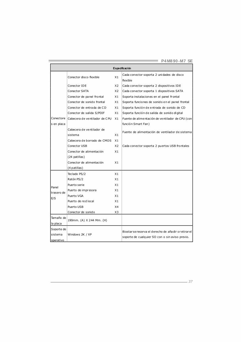
Especificación
Conector disco flexible X1 Cada conector soporta 2 unidades de disco
flexible
Conector IDE X2 Cada conector soporta 2 dispositivos IDE
Conector SATA X2 Cada conector soporta 1 dispositivos SATA
Conector de panel frontal X1 Soporta instalaciones en el panel frontal
Conector de sonido frontal X1 Soporta funciones de sonido en el panel frontal
Conector de entrada de CD X1 Soporta función de entrada de sonido de CD
Conector de salida S/PDIF X1 Soporta función de salida de sonido digital
Cabecera de ventilador de CPU X1 Fuente de alimentación de ventilador de CPU (con
función Smart Fan)
Cabecera de ventilador de
sistema X1 Fuente de alimentación de ventilador de sistema
Cabecera de borrado de CMOS X1
Conector USB X2 Cada conector soporta 2 puertos USB frontales
Conector de alimentación X1
(24 patillas)
Conectore
s en placa
Conector de alimentación X1
(4 patillas)
Panel
trasero de
E/S
Teclado PS/2 X1
Ratón PS/2 X1
Puerto serie X1
Puerto de impresora X1
Puerto VGA X1
Puerto de red local X1
Puerto USB X4
Conector de sonido X3
Tamaño de
la placa 190mm. (A) X 244 Mm. (H)
Soporte de
sistema
operativo
Windows 2K / XP Biostar se reserva el derecho de añadir o retirar el
soporte de cualquier SO con o sin aviso previo.

Motherboard Manual
38
PORTUGUESE ESPECIFICAÇÕES
CPU
LGA 775
Processador Intel Core2Duo/ Pentium
4 / Pentium D / Celeron D até 3,8 GHz
*It is recommended to use processors
with 95W power consumption.
Suporta as tecnologias Hyper-Threading /
Execute Disable Bit / Enhanced Intel SpeedStep®
/ Intel Arquitecture -64 / Extended Memory 64
FSB 533 / 800 / 1066 MHz
Chipset VIA P4M890
VIA VT8237A
Placa
gráfica Integrada no chipset UniChrome Pro Memória de vídeo máxima partilhada: 64 MB
Especificaç
ão Super
I/O
ITE 8712F
Proporciona as funcionalidades mais
utilizadas em termos da especificação
Super I/O.
Interface LPC (Low Pin Count).
Iniciativas para control o do ambiente
Monitorização do hardware
Controlador da velocidade da ventoinha
Função "Smart Guardian" da ITE
Memória
principal
Ranhuras DIMM DDR2 x 2
Suporta módulos DDR2 533
Cada módulo DIMM suporta uma
memória DDR2 de 256MB /512 MB / 1
GB / 2GB
Capacidade máxima de memória: 4
GB
Módulo de memória DDR2 de canal simples
Os módulos DIMM registados e os DIMM ECC não
são suportados
IDE
Controlador IDE integrado
Modo Bus master Ultra DMA 33 / 66 /
100 / 133
Suporta o modo PIO 0~4,
SATA
Controlador Serial ATA integrado
Velocidades de transmissão de dados
até 1.5 Gb/s.
Compatibilidade com a especificação SATA versão
1.0.
LAN PHY Realtek RTL 8201CL PHY Auto negociação de 10 / 100 MB/s
Capacidade semi/full-duplex
Codec de
som ALC861VD
Suporta a especificação High-Definition Audio
Saída de áudio de 5.1 canais
Ranhura PCI x2
Ranhura PCI Express x16 x1 Ranhuras
Ranhura PCI Express x 1 x1

P4M890-M7 SE
39
ESPECIFICAÇÕES
Conector da unidade de
disquetes x1 Cada conector suporta 2 unidades de disquetes
Conector IDE x2 Cada conector suporta 2 dispositivos IDE
Conector SATA x2 Cada conector suporta 1 dispositivo SATA
Conector do painel frontal x1 Para suporte de várias funções no painel frontal
Conector de áudio frontal x1 Suporta a função de áudio no painel frontal
Conector para entrada de CDs x1 Suporta a entrada de áudio a partir de CDs
Conector de saída S/PDIF x1 Suporta a saída de áudio digital
Conector da ventoinha da CPU x1 Alimentação da ventoinha da CPU (com a função
Smart Fan)
Conector da ventoinha do
sistema x1 Alimentação da ventoinha do sistema
Conector para limpeza do CMOS x1
Conector USB x2 Cada conector suporta 2 portas USB no painel
frontal
Conector de alimentação x1
(24 pinos)
Conectore
s na placa
Conector de alimentação x1
(4 pinos)
Entradas/
Saídas no
painel
traseiro
Teclado PS/2 x1
Rato PS/2 x1
Porta série x1
Porta para impressora x1
Porta VGA x1
Porta LAN x1
Porta USB x4
Tomada de áudio x3
Tamanho
da pl aca 190 mm (L) X 244 mm (A)
Sistemas
operativos
suportado
s
Windows 2K / XP
A Biostar reserva-se o direito de adicionar ou
remover suporte para qualquer sistema operativo
com ou sem aviso prévio.

Motherboard Manual
40
POLISH
SPEC
Procesor
LGA 775
Procesor Intel Core2Duo/ Pentium 4 /
Pentium D / Celeron D do 3,8 GHz
*It is recommended to use processors
with 95W power consumption.
Obsługa Hyper-Threading / Execute Disabl e Bit /
Enhanced Intel SpeedStep® / Intel
Architecture-64 / Extended Memory 64
Technology
FSB 533 / 800 / 1066 MHz
Chipset VIA P4M890
VIA VT8237A
Grafika Zintegrowana w chipsecie UniChrome
Pro
Maks. wielkość współdzielonej pamięci video
wynosi 64MB
Pamięć
główna
Gniazda DDR2 DIMM x 2
Obsługa DDR2 533
Każde gniazdo DIMM obsługuje
moduły 256MB /512MB / 1GB / 2GB
DDR2
Maks. wielkość pamięci 4GB
Moduł pamięci DDR2 z trybem pojedynczego
kanału
Brak obsługi Registered DIMM oraz ECC DIMM
Super I/O
ITE 8712F
Zapewnia najbardziej powszechne
funkc je Super I/O.
Interfejs Low Pin Count
Funkcje kontroli warunków prac y,
Monitor H/W
Kontroler prędkości wentylatora
Funkcja ITE "Smart Guardian"
IDE
Zintegrowany kontroler IDE
Ultra DMA 33 / 66 / 100 / 133 Tryb
Bus Master
obsługa PIO tryb 0~4,
SATA Zintegrowany kontroler Serial ATA
Transfer danych do 1.5 Gb/s. Zgodność ze specyfikacją SATA w wersji 1.0.
LAN PHY Realtek RTL 8201CL PHY
10 / 100 Mb/s z automatyczną negocjacją
szybkości
Działanie w trybie połowicznego / pełnego
dupleksu
Kodek
dźwiękowy ALC861VD
Obsługa High-Definition Audio
5.1 kanałowe wyjście audio
Gniazdo PCI x2
Gniazdo PCI Express x16 x1 Gniazda
Gniazdo PCI Express x 1 x1
P4M890-M7 SE
41
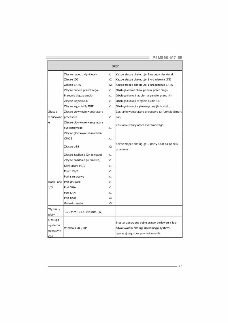
SPEC
Złącze napędu dyskietek x1 Każde złącze obsługuje 2 napędy dyskietek
Złącze IDE x2 Każde złącze obsługuje 2 urządzenia IDE
Złącze SATA x2 Każde złącze obsługuje 1 urządzenie SATA
Złącze panela przedniego x1 Obsługa elementów panela przedniego
Przednie złącze audio x1 Obsługa funkcji audio na panelu przednim
Złącze wejścia CD x1 Obsługa funkcji wejścia audio CD
Złącze wyjścia S/PDIF x1 Obsługa funkcji cyfrowego wyjścia audio
Złącze główkowe wentylatora
procesora x1
Zasilanie wentylatora procesora (z funkcją Smart
Fan)
Złącze główkowe wentylatora
systemowego x1 Zasilanie wentylatora systemowego
Złącze główkowe kasowania
CMOS x1
Złącze USB x2 Każde złącze obsługuje 2 porty USB na panelu
przednim
Złącze zasilania (24 pinowe) x1
Złącza
wbudowan
e
Złącze zasilania (4 pinowe) x1
Back Panel
I/O
Klawiatura PS/2 x1
Mysz PS/2 x1
Port szeregowy x1
Port drukarki x1
Port VGA x1
Port LAN x1
Port USB x4
Gniazdo audio x3
Wymiary
płyty 190 mm (S) X 244 mm (W)
Obsluga
systemu
operacyjn
ego
Windows 2K / XP
Biostar zastrzega sobie prawo dodawania lub
odwoływania obsługi dowolnego systemu
operacyjnego bez powiadomienia.
Motherboard Manual
42
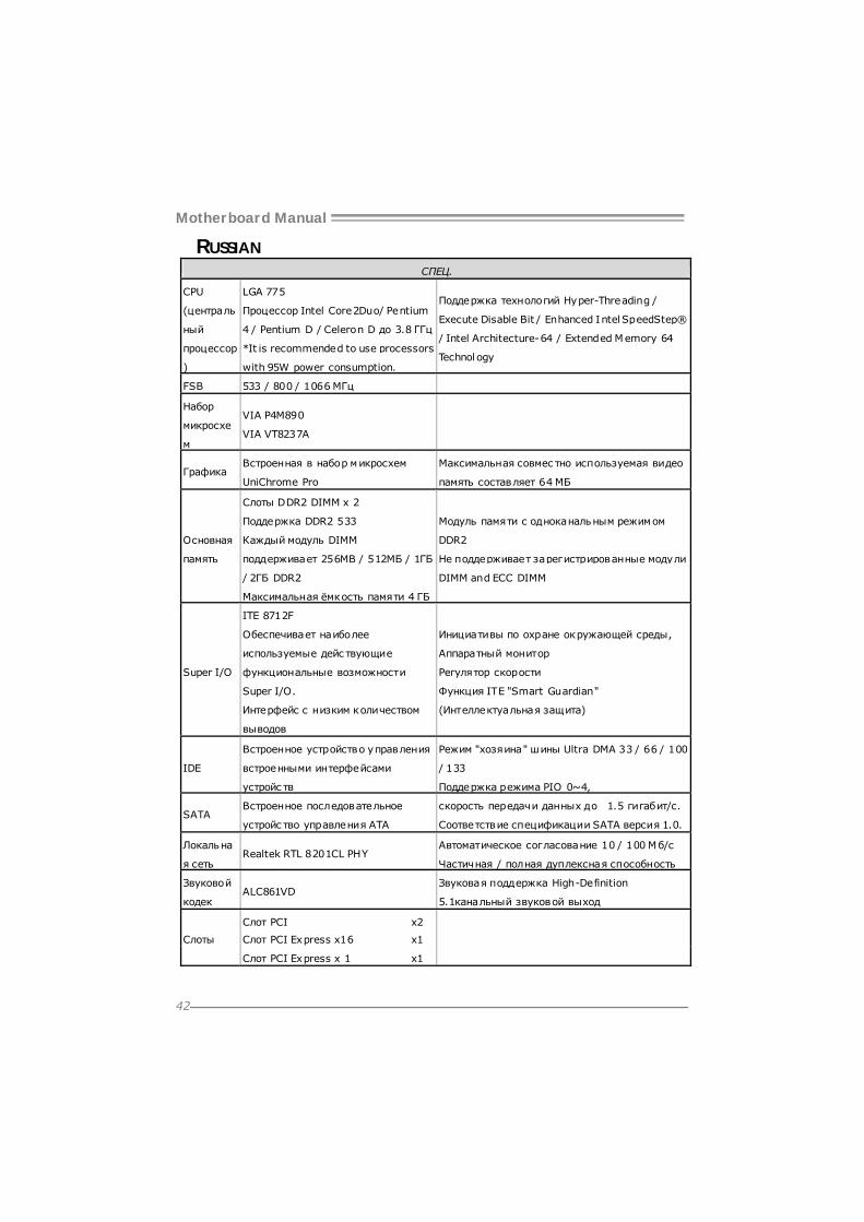
RUSSIAN СПЕЦ.
CPU
(централь
ный
процессор
)
LGA 775
Процессор Intel Core2Duo/ Pentium
4 / Pentium D / Celeron D до 3.8 ГГц
*It is recommended to use processors
with 95W power consumption.
Поддержка технологий Hyper-Threading /
Execute Disable Bit / Enhanced Intel SpeedStep®
/ Intel Architecture-64 / Extended Memory 64
Technology
FSB 533 / 800 / 1066 МГц
Набор
микросхе
м
VIA P4M890
VIA VT8237A
Графика Встроенная в набор микросхем
UniChrome Pro
Максимальная совмес тно используемая видео
память составляет 64 МБ
Основная
память
Слоты DDR2 DIMM x 2
Поддержка DDR2 533
Каждый модуль DIMM
поддерживает 256MB / 512МБ / 1ГБ
/ 2ГБ DDR2
Максимальная ёмкость памяти 4 ГБ
Модуль памяти с одноканальным режимом
DDR2
Не поддерживает зарегистрированные модули
DIMM and ECC DIMM
Super I/O
ITE 8712F
Обеспечивает наиболее
используемые дейс твующие
функциональные возможности
Super I/O.
Интерфейс с низким количеством
выводов
Инициативы по охране окружающей среды,
Аппаратный монитор
Регулятор скорости
Функция ITE "Smart Guardian"
(Интеллектуальная защита)
IDE
Встроенное устройство управления
встроенными интерфейсами
устройс тв
Режим "хозяина" шины Ultra DMA 33 / 66 / 100
/ 133
Поддержка режима PIO 0~4,
SATA Встроенное последовательное
устройс тво управления ATA
скорость передачи данных до 1.5 гигабит/с.
Соответствие спецификации SATA версия 1.0.
Локальна
я сеть Realtek RTL 8201CL PHY
Автоматическое согласование 10 / 100 Мб/с
Частичная / полная дуплексная способность
Звуковой
кодек ALC861VD
Звуковая поддержка High-Definition
5.1канальный звуковой выход
Слот PCI x2
Слот PCI Express x16 x1 Слоты
Слот PCI Express x 1 x1
P4M890-M7 SE
43
СПЕЦ.
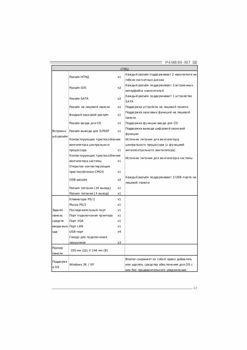
Разъём НГМД x1 Каждый разъём поддерживает 2 накопителя на
гибких магнитных дисках
Разъём IDE x2 Каждый разъём поддерживает 2 встроенных
интерфейса накопителей
Разъём SATA x2 Каждый разъём поддерживает 1 устройство
SATA
Разъём на лицевой панели x1 Поддержка устройств на лицевой панели
Входной звуковой раз ъём x1 Поддержка звуковых функций на лицевой
панели
Разъём ввода для CD x1 Поддержка функции ввода для CD
Разъём вывода для S/PDIF x1 Поддержка вывода цифровой звуковой
функции
Контактирующее приспособление
вентилятора центрального
процессора x1
Источник питания для вентилятора
центрального процессора (с функцией
интеллектуального вентилятора)
Контактирующее приспособление
вентилятора системы x1 Источник питания для вентилятора сис темы
Открытое контактирующее
приспособление CMOS x1
USB-разъём x2 Каждый разъём поддерживает 2 USB-порта на
лицевой панели
Разъем питания (24 вывод) x1
Встроенн
ый разъём
Разъем питания (4 вывод) x1
Задняя
панель
средств
ввода-выв
ода
Клавиатура PS/2 x1
Мышь PS/2 x1
Последовательный порт x1
Порт подключения принтера x1
Порт VGA x1
Порт LAN x1
USB-порт x4
Гнездо для подключения
наушников x3
Размер
панели 190 мм (Ш) X 244 мм (В)
Поддержк
а OS Windows 2K / XP
Biostar сохраняет за собой право добавлять
или удалять средства обеспечения для OS с
или без предварительного уведомления.
Motherboard Manual
44
ARABIC
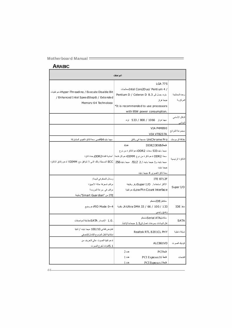
المواصفات
المعالجة وحدة
ة المرآزي
LGA 775
Intel Core2Duo/ Pentiمعالجات um 4 /
Pentium D / Celeron D 8.3صل إلى ي تردد ب
جيجا هرتز
*It is recommended to use processors
with 95W power consumption.
ات تدعم تقني Hyper-Threading / Execute Disable Bit
/ Enhanced Intel SpeedStep® / Extended
Memory 64 Technology
األمامي الناقل
الجانبي ميجا هرتز 1066 / 800 / 533 تردد
الشرائح مجموعة VIA P4M890
VIA VT8237A
ة لذاآرة الفيديو المشترآة أقصى سع UniChrome Pro مدمجة في رقائق بطاقة الرسومات ميجا بايت64
ذاآرة لرئيسية ال ا
4عدد DDR2 DIMMفتحة
ة تدعم لذاآر DDR2 نوع من ا 533 سعات بايت ميجا
DIMM فتحة آل تدعم ة تدعم DDR2 نوع من ذاآر سعة
256 بايت ميجا /512 2 / بايت جيجا 1و بايت ميجا
بايت جيجا
بايت جيجا 4 قصوى ذاآرة سعة
آرة وحدة DDR2 ذا القناة أحادية
ذاآرة رقائق تدعم ال DIMM ال ي وتلك المسجلة ECC مع تتوافق ال الت
Super I/O
ITE 8712F
Super I وظيفة توفر /O استخدامًا األآثر.
Low Pi تقنية دعمت n Count Interface
:البيئة في التحكم وسائل
األجهزة حالة لمعرفة مراقب
ة سرعة في مراقب المروح
"Smart Guardian"وظيفة ITE من
IDE منفذ
IDE متحكم متكامل
Ultra DMA 33 / 66 / 100 / 133ناقل بتقنية
رئيسي وضع
PIO Mode 0~4دعم وضع
SATA Serial ATA متحكم متكامل
.ثانية/جيجابت 1.5إلى تصل بسرعات البيانات نقل SATA لمواصفات مطابقة .1.0 اإلصدار
داخلية شبكة Realtek RTL 8201CL PHY ثانية/ ميجا بايت 10/100تفاوض تلقائي
النصفي/إمكانية النقل المزدوج الكامل
الصوت آوديك ALC861VD تدعم تقنية الصوت عالي التعريف من
قنوات لخرج الصوت5.1
2عدد PCIفتحة
الفتحات 1عدد x16 PCI Expressفتحة
1عدد PCI Express x 1فتحة

P4M890-M7 SE
45
المواصفات
المرنة لألقراص محرآين يدعم 1عدد منفذ محرك أقراص مرنة
IDE أجهزة من اثنين منفذ آل يدعم 2عدد IDEمنفذ
SATA أجهزة من واحد منفذ آل يدعم 2عدد SATAمنفذ
األمامية اللوحة تجهيزات يدعم 1عدد منفذ اللوحة األمامية
األمامية باللوحة الصوت وظيفة يدعم 1دد ع منفذ الصوت األمامي
ج القرص صوت دخل وظيفة يدعم 1عدد CD-INمنفذ المدم
الرقمي الصوت خرج وظيفة يدعم 1عدد S/PDIFمنفذ خرج
)Smart Fan وظيفة مع( المعالجة وحدة لمروحة الطاقة لتوصيل 1عدد وصلة مروحة وحدة المعالجة المرآزية
النظام لمروحة الطاقة لتوصيل 1عدد ظاموصلة مروحة الن
1عدد CMOSوصلة مسح
USB فتحتي منفذ آل يدعم 2عدد USBمنفذ األمامية باللوحة
1عدد )دبوس24(منفذ توصيل الطاقة
سطح على المنافذ
ة اللوح
1عدد )دبابيس4(منفذ توصيل الطاقة
خرج/دخل منافذ
الخلفية اللوحة
1عدد PS/2لوحة مفاتيح
1عدد PS/2 ماوس
1عدد منفذ تسلسلي
1عدد منفذ طابعة
1عدد VGAمنفذ
1عدد منفذ شبكة اتصال محلية
4عدد USBمنافذ
3عدد مقبس صوت
للوحة حجم ا )ارتفاع(مم X 244) عرض(مم 190
أنظمة دعم
التشغيلWindows 2K / XP
Biostar تحتفظ م ألي الدعم إزالة أو إضافة في بحقها تشغيل نظا
.إخطار بدون أو بإخطار

Motherboard Manual
46
JAPANESE
仕様
CPU
LGA 775
Intel Core2Duo/ Pentium 4 / Pentium
D / Celeron D processor up to 3.8 GHz
*It is recommended to use processors
with 95W power consumption.
Hyper-Threading / Exec ute Disabl e Bit /
Enhanced Intel SpeedStep® / Intel
Architecture-64 / Extended Memory 64
Technology をサポートします
FSB 533 / 800 / 1066 MHz
チップセッ
ト
VIA P4M890
VIA VT8237A
グラフィッ
クス UniChrome Pro チップセットに統合 最大の共有ビデオメモリは64MBです
メインメモ
リ
DDR2 DIMMスロット x 2
DDR2 533をサポート
各DIMMは 256/512MB/1GB/2GB
DDR2をサポート
最大メモリ容量4GB
シングル チャンネルモードDDR2メモリモジュール
登録済みDIMMとECC DIMMはサポートされません
Super I/O
ITE 8712F
もっとも一般に使用されるレガシー
Super I/O機能を採用しています。
低ピンカウントインターフェイス
環境コントロールイニシアチブ、
H/Wモニター
ファン速度コントローラ/ モニター
ITEの「スマートガーディアン」機能
IDE
統合IDEコントローラ
Ultra DMA 33 / 66 / 100 / 133バスマス
タモード
PIO Mode 0~4のサポート、
SATA 統合シリアルATAコントローラ
最高1.5 Gb/秒のデータ転送速度 SATAバージョン1.0仕様に準拠。
LAN PHY Realtek RTL 8201CL PHY 10 / 100 Mb/秒のオートネゴシエーション
半/全二重機能
サウンド
Codec ALC861VD
ハイデフィニションオーディオのサポート
5.1 チャンネルオーディオアウト
PCIスロット x2
PCI Express x16スロット x1 スロット
PCI Express x 1スロット x1

P4M890-M7 SE
47
仕様
フロッピーコネクタ x1 各コネクタは2つのフロッピードライブをサポートし
ます
IDEコネクタ x2 各コネクタは2つのIDEデバイスをサポートします
SATAコネクタ x2 各コネクタは1つのSATAデバイスをサポートします
フロントパネルコネクタ x1 フロントパネル機能をサポートします
フロントオーディオコネクタ x1 フロントパネルオーディオ機能をサポートします
CDインコネクタ x1 CDオーディオイン機能をサポートします
S/PDIFアウトコネクタ x1 デジタルオーディオアウト機能をサポートします
CPUファンヘッダ x1 CPUファン電源装置(スマートファン機能を搭載)
システムファンヘッダ x1 システムファン電源装置
CMOSクリアヘッダ x1
USBコネクタ x2 各コネクタは2つのフロントパネルUSBポートをサポ
ートします
電源コネクタ(24ピン) x1
オンボード
コネクタ
電源コネクタ(4ピン) x1
背面パネル
I/O
PS/2キーボード x1
PS/2マウス x1
シリアルポート x1
プリンタポート x1
VGAポート x1
LANポート x1
USBポート x4
オーディオジャック x3
ボードサイ
ズ 190 mm (幅) X 244 mm (高さ)
OSサポー
ト Windows 2K / XP
Biostarは事前のサポートなしにOSサポートを追加ま
たは削除する権利を留保します。
2007/04/11

P4M890-M7 SE BIOS Setup
i
BIOS Setup.................................................................................................1
1 Main Menu...............................................................................................3
2 Standard CMOS Features......................................................................7
3 Advanced BIOS Features .......................................................................9
4 Advanced Chipset Features..................................................................17
5 Integrated Peripherals..........................................................................21
6 Power Management Setup....................................................................27
7 PnP/PCI Configurations.......................................................................32
8 PC Health Status ...................................................................................35
9 Performance Booster Zone...................................................................37

P4M890-M7 SE
1
BIOS Setup
Introduction The purpose of this manual is to describe the settings in the Phoenix-Award™ BIOS Setup program on this motherboard. The Setup program allows users to modify the basic system configuration and save these settings to CMOS RAM. The power of CMOS RAM is supplied by a battery so that it retains the Setup information when the power is turned off. Basic Input-Output System (BIOS) determines what a computer can do without accessing programs from a disk. This system controls most of the input and output devices such as keyboard, mouse, serial ports and disk drives. BIOS activates at the first stage of the booting process, loading and executing the operating system. Some additional features, such as virus and password protection or chipset fine-tuning options are also included in BIOS. The rest of this manual will to guide you through the options and settings in BIOS Setup.
Plug and Play Support This PHOENIX-AWARD BIOS supports the Plug and Play Version 1.0A speci fication and ESCD (Extended System Configuration Data) write.
EPA Green PC Support This PHOENIX-AWARD BIOS supports Version 1.03 of the EPA Green PC speci fication.
APM Support This PHOENIX-AWARD BIOS supports Version 1.1&1.2 of the Advanced Power Management (APM) speci fication. Power management features are implemented via the System Management Interrupt (SMI). Sleep and Suspend power management modes are supported. Power to the hard disk drives and video monitors can also be managed by this PHOENIX-AWARD BIOS.

P4M890-M7 SE
2
ACPI Support Phoenix-Award ACPI BIOS support Version 1.0b of Advanced Configuration and Power interface speci fi cation (ACPI). It provides ASL code for power management and device configuration capabilities as defined in the ACPI speci fication, developed by Microsoft, Intel and Toshiba.
PCI Bus Support This PHOENIX-AWARD BIOS also supports Version 3.0 of the Int el PCI (Peripheral Component Interconnect) local bus specification.
DRAM Support DDR SDRAM (Double Data Rate Synchronous DRAM) is supported.
Supported CPUs This PHOENIX-AWARD BIOS supports the Intel CPU.
Using Setup Use the arrow keys to highlight items in most of the place, press <Enter> to select, use the <PgUp> and <PgDn> keys to change entries, press <F1> for help and press <Esc> to quit. The following table provides more detail about how to navigate in the Setup program by using the keyboard.
Keystroke Function Up arrow Move to previous item Down arrow Move to next item Left arrow Move to the item on the left (menu bar) Right arrow Move to the item on the right (menu bar) Move Enter Move to the item you desired PgUp key Increase the numeric val ue or make changes PgDn key Decrease the numeric value or make changes + Key Increase the numeric val ue or make changes - Key Decrease the numeric value or make changes Esc key Main Menu – Quit and not save changes into CMOS
Status Page Setup Menu and Option Page Setup Menu – Exit Current page and r eturn to M ain Menu
F1 key General help on Setup navigation keys F5 key Load pr evious values from CMOS F7 key Load the opti mized defaults F10 key Save all the CMOS changes and exit

P4M890-M7 SE
3
1 Main Menu Once you enter Phoenix-Award BIOS™ CMOS Setup Utility, the Main Menu will appear on the screen. The Main Menu allows you to select from several setup functions. Use the arrow keys to select among the items and press <Enter> to accept and enter the sub-menu.
Figure 1: Main Menu
Standard CMOS Features This submenu contains industry standard configurable options.
Advanced BIOS Features This submenu allows you to configure advanced features of the BIOS.
!! WARNING !!
For better system performance, the BIOS firmware is being continuously updated. The BIOS information described in this manual (Figure 1, 2, 3, 4, 5, 6, 7, 8, 9) is for your reference only. The actual BIOS information and settings on board may be slightly different from this manual.

P4M890-M7 SE
4
Advanced Chipset Features This submenu allows you to configure special chipset features.
Integrated Peripherals This submenu allows you to configure cert ain IDE hard drive options and Programmed Input/ Output features.
Power Management Setup This submenu allows you to configure the power management features.
PnP/PCI Configurations This submenu allows you to configure cert ain “ Plug and Play” and PCI options.
PC Health Status This submenu allows you to monitor the hardware of your system.
Performance Booster Zone This submenu allows you to change CPU Vcore Voltage and CPU/PCI clock. (However, we suggest you to use the default setting. Changing the voltage and clock improperly may damage the CPU or M/B!)
Load Optimized Defaults This selection allows you to reload the BIOS when problem occurs during system booting sequence. These configurations are factory settings optimized for this system. A confirmation message will be displayed before defaults are set.

P4M890-M7 SE
5
Set Supervisor Password Setting the supervisor password will prohibit everyone except the supervisor from making changes using the CMOS Setup Utility. You will be prompted with to enter a password.
Set User Password If the Supervisor Password is not set, then the User Password will function in the same way as the Supervisor Password. If the Supervisor Password is set and the User Password is set, the “User” will only be able to view configurations but will not be able to change them.
Save & Exit Setup Save all configuration changes to CMOS (memory) and exit setup. Confirmation message will be displayed before proceeding.
Exit Without Saving Abandon all changes made during the current session and exit setup. Confirmation message will be displayed before proceeding.

P4M890-M7 SE
6
Upgrade BIOS This submenu allows you to upgrade bios.

P4M890-M7 SE
7
2 Standard CMOS Features The items in Standard CMOS Setup Menu are divided into several categori es. Each category includes no, one or more than one setup items. Use the arrow keys to highlight the item and then use the<PgUp> or <PgDn> keys to select the value you want in each item.
Figure 2: Standard CMOS Setup
Main Menu Selections
This table shows the items and the available options on the Main Menu.
Item Options Description
Date mm : dd : yy
Set the system date. Note that the ‘Day ’ automatically changes when you set the date.
Time hh : mm : ss Set the system internal clock.
IDE Channel 0 Master Options are in its sub menu.
Press <Enter> to enter the sub menu of detailed options
IDE Channel 0 Slav e Options are in its sub menu.
Press <Enter> to enter the sub menu of detailed options.

P4M890-M7 SE
8
Item Options Description
IDE Channel 1 Master Options are in its sub menu.
Press <Enter> to enter the sub menu of detailed options.
IDE Channel 1 Slav e Options are in its sub menu.
Press <Enter> to enter the sub menu of detailed options.
Driv e A
Driv e B
360K, 5.25 in
1.2M, 5.25 in 720K, 3.5 in 1.44M, 3.5 in
2.88M, 3.5 in None
Select the ty pe of f loppy disk drive installed in your sy stem.
Halt On
All Errors No Errors
All, but Key board All, but Diskette All, but Disk/ Key
Select the situation in which y ou want the BIOS to stop the POST process and notify y ou.
Base Memory N/A Displays the amount of conv entional memory detected during boot up.
Extended Memory N/A Displays the amount of extended memory detected during boot up.
Total Memory N/A Displays the total memory av ailable in the system.

P4M890-M7 SE
9
3 Advanced BIOS Features Figure 3: Advanced BIOS Setup
Boot Seq & Floppy Setup This item allows you to setup boot sequence & Floppy.

P4M890-M7 SE
10
Hard Disk Boot Priority The BIOS will attempt to arrange the Hard Disk boot sequence automatically. You can change the Hard Disk booting sequence here.
The Choices: Pri. Master, Pri. Slave, Sec. Master, Sec. Slave, USB HDD0, USB HDD1, USB HDD2, and Bootable Add-in Cards.
First/Second/Third Boot Dev ice The BIOS will attempt to load the operating system in this order.
The Choices: Floppy, LS120, Hard Disk, CDROM, ZIP100, USB-FDD, USB-ZIP, USB-CDROM, LAN, Disabled.
Boot Other Dev ice When enabled, BIOS will try to load the operating system from other device when it failed to load from the three devices above.
The Choices: Enabled (default), Disabled
Swap Floppy Drive For systems with two floppy drives, this option allows you to swap logical drive assignments.
The Choices: Disabled (default), Enabled.
P4M890-M7 SE
11
Boot Up Floppy Seek When enabled, System will test the floppy drives to determine if they have 40 or 80 tracks during boot up. Disabling this option reduces the time it takes to boot-up.
The Choices: Enabled (default), Disabled.
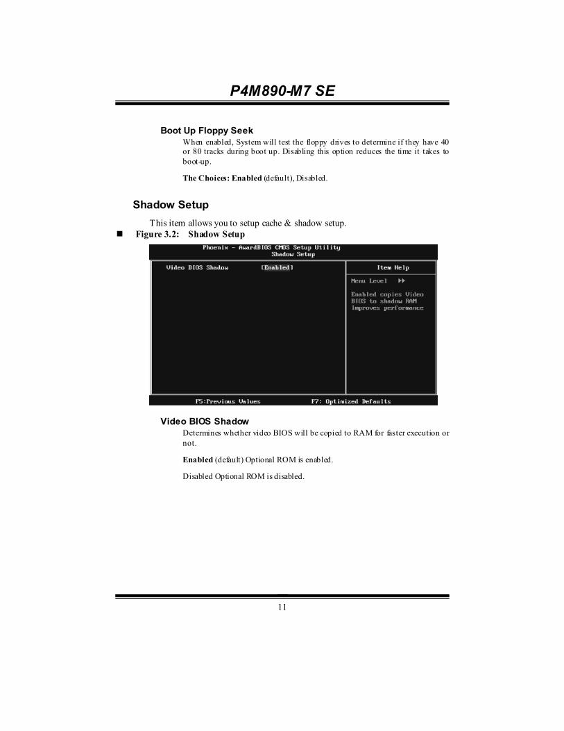
Shadow Setup This item allows you to setup cache & shadow setup.
Figure 3.2: Shadow Setup
Video BIOS Shadow
Determines whether video BIOS will be copied to RAM for faster execution or not.
Enabled (default) Optional ROM is enabled.
Disabled Optional ROM is disabled.

P4M890-M7 SE
12
Cache Setup
CPU L1 & L2 Cache Depending on the CPU/chipset in use, you may be able to increase memory access time with this option.
Enabled (default) Enable cache.
Disabled Disable cache.
CPU L3 Cache Depending on the CPU/chipset in use, you may be able to increase memory access time with this option.
Enabled (default) Enable cache.
Disabled Disable cache.
CPU L2 Cache ECC Checking This item allows you to enable/disable CPU L2 Cache ECC Checking.
The Choices: Enabled (default), Disabled.

P4M890-M7 SE
13
CPU Feature
Delay Prior to Thermal
Set this item to enable the CPU Thermal function to engage after the specified time.
The Choices: 4 Min, 8 Min, 16Min (default), 32 Min.
Thermal Management This option allows you to select the way to control the “ Thermal Management.”
The Choices: Thermal Monitor 1 (default), Thermal Monitor 2.
TM2 Bus Ratio This option represents the frequency (bus ratio) of the throttled performance state that will be initiated when the on-die sensor detects temperature increase.
Min= 0 Max= 255 Key in a DEC number.
The Choices: 0 X (default)
TM2 Bus VID This option represents the voltage of the throttled performance state that will be initiated when the on-die sensor detects temperature increase.
The Choices: 0.8375V (default), 0.8375-1.6000.

P4M890-M7 SE
14
Limit CPUID MaxVal Set Limit CPUID MaxVal to 3, it should be “Disabled” for Windows XP.
The Choices: Disabled (default), Enabled.
C1E Function This item allows you to configure the Enhanced Halt State (C1E) function, which may reduce the power consumption of your system when the system is idle.
The Choices: Auto (default),Disabled.
Execute Disable Bit This item allows you to configure the Execute Disabled Bit function, which protects your system from buffer overflow attacks.
The Choices: Enabled (default), Disabled.
Virtualization Technology Virtualization Technology can virtually separate your system resource into several parts, thus enhance the performance when running virtual machines or multi interface systems.
The Choices: Enabled (default), Disabled.
Virus Warning This option allows you to choose the VIRUS Warning feature that is used to protect the IDE Hard Disk boot sector. If this function is enabled and an attempt is made to write to the boot sector, BIOS will display a warning message on the screen and sound an alarm beep. Disabled (default) Virus protection is disabled. Enabled Virus protection is activated.
Hyper-Threading Technology This option allows you to enable or disabled Hyper-Threading Technology. “ Enabled” for Windows XP and Linux 2.4.x (OS optimized for Hyper-Threading Technology). “ Disable” for other OS (OS not optimized for Hyper-Threading Technology). The Choices: Enabled (default), Disabled.

P4M890-M7 SE
15
Quick Power On Self Test Enabling this option will cause an abridged version of the Power On Self-Test (POST) to execute after you power up the computer. Disabled Normal POST. Enabled (default) Enable quick POST.
Boot Up NumLock Status Selects the NumLock State after the system switched on. The Choices: On (default) Numpad is number keys. Off Numpad is arrow keys.
Typematic Rate Setting When a key is held down, the keystroke will repeat at a rate determined by the keyboard controller. When enabled, the typematic rate and typematic delay can be configured. The Choices: Disabled (default), Enabled.
Typematic Rate (Chars/Sec) Sets the rate at which a keystroke is repeated when you hold the key down. The Choices: 6 (default), 8, 10, 12, 15, 20, 24, 30.
Typematic Delay (Msec) Sets the delay time after the key is held down before it begins to repeat the keystroke. The Choices: 250 (default), 500, 750, 1000.
Security Option This option will enable only individuals with passwords to bring the system online and/or to use the CMOS Setup Utility. System: A password is required for the system to boot and is also required to access the Setup Utility. Setup (default): A password is required to access the Setup Utility only. This will only apply if passwords are set from the Setup main menu.

P4M890-M7 SE
16
MPS Version Control For OS The BIOS supports version 1.1 and 1.4 of the Intel multiprocessor speci fication. Select version supported by the operation system running on this computer. The Choices: 1.4 (default), 1.1.
OS Select For DRAM > 64MB A choice other than Non-OS2 is only used for OS2 systems with memory exceeding 64MB. The Choices: Non-OS2 (default), OS2.
HDD S.M.A.R.T. Capability This item allows you to enable/disable HDD S.M.A.R.T. Capability. The Choices: Disabled (default), Enabled.
Small Logo(EPA) Show This item allows you to select whether the “Small Logo” shows. Enabled (default) “ Small Logo” shows when system boots up. Disabled No “Small Logo” shows when system boots The Choices: Enabled (default), Disabled
Summary Screen Show This item allows you to enable/disable the summary screen. Summary screen means system configuration and PCI device listing. The Choices: Disabled (default), Enabled.

P4M890-M7 SE
17
4 Advanced Chipset Features This submenu allows you to configure the speci fic features of the chipset installed on your system. This chipset manage bus speeds and access to system memory resources, such as DRAM. It also coordinates communications with the PCI bus. The default settings that came with your system have been optimized and therefore should not be changed unless you are suspicious that the settings have been changed incorrectly.
Figure 4: Advanced Chipset Setup

P4M890-M7 SE
18
AGP & P2P Bridge Control Highlight “Press Enter” next to the “ AGP & P2P Bridge Control” label and pressing the enter key will take you a submenu with the following options:
Figure 4.1: AGP & P2P Bridge Control
AGP Aperture Size
Select the size of the Accelerated Graphics Port (AGP) aperture. The aperture is a portion of the PCI memory address range dedicated for graphics memory address space. Host cycles that hit the aperture range are forwarded to the AGP without the need of translation. The Choices: 32M, 64M, 128M (default), 256M.
AGP 2.0 Mode This item allows you to select the AGP Mode. The Choices: 8X (default), 4X.
AGP Master 1 WS Write When enabled, writes to the AGP (Accelerated Graphics Port) are executed with one wait states.
The Choices: Enabled (default), Disabled.

P4M890-M7 SE
19
AGP Master 1 WS Read When enabled, read to the AGP (Accelerated Graphics Port) are executed with one wait states.
The Choices: Enabled (default), Disabled.
VGA Share Memory Size This item allows you to select the VGA share memory size. The Choices: 64M (default), 16M, 32M, 128M, 256M, Disabled
Direct Frame Buffer This item allows you to disabled or enabled direct frame buffer The Choices: Enabled (default), Disabled.
CPU & PCI Bus Control By highlighting the “Press Enter” label next to the “CPU & PCI Bus Control” and press the enter key, it will take you a submenu with the following options:
Figure 4.2: CPU & PCI Bus Control
PCI Master 0 WS Write
When enabled, writes to the PCI bus are executed with zero-wait states.
The Choices: Enabled (default), Disabled.

P4M890-M7 SE
20
PCI Delay Transaction The chipset has an embedded 32-bit posted write buffer to support delay transactions cycles. Select Enabled to support compliance with PCI specification.
The Choices: Enabled (default), Disabled.
Vlink mode selection This item allows you to select Vlink mode.
The Choices: By Auto (default), Mode 0 , Mode 1.
VLink 8X Support This item allows you to enable or disable VLink 8X support.
The Choices: Enabled (default), Disabled.
VIA PWR Management The Choices: Enabled (default), Disabled.
Memory Hole You can reserve this area of system memory for ISA adapter ROM. When this area is reserved it cannot be cached. Check the user information of peripherals that need to use this area of system memory for the memory requirements. The Choices: Disabled (default), Enabled.
System BIOS Cacheable Selecting the “ Enabled” option allows caching of the system BIOS ROM at F0000h-FFFFFh, which is able to improve the system performance. However, any programs that attempts to write to this memory block will cause conflicts and result in system errors. The Choices: Enabled (default), Disabled.
Top Performance The Choices: Disabled (default), Enabled.

P4M890-M7 SE
21
5 Integrated Peripherals Figure 5. Integrated Peripherals
VIA OnChip IDE Device Highlight the “Press Enter” label next to the “ VIA OnChip IDE Device” label and press enter key will take you a submenu with the following options:

P4M890-M7 SE
22
SATA Controller This option allows you to enable the on-chip Serial ATA.
The Choices: Enabled (default), Disabled.
SATA Controller Mode This option allows you to select SATA Mode.
The Choices: RAID, IDE (default).
IDE DMA Transfer Access This item allows you to enable or disable the IDE DMA transfer access.
The Choices: Enabled (default), Disabled.
On-chip IDE Channel 0/1 The motherboard chipset contains a PCI IDE interface with support for two IDE channels. Select “Enabled” to activate the first and/or second IDE interface. Select “Disabled” to deactivate an interface if you are going to install a primary and/or secondary add-in IDE interface.
The Choices: Enabled (default), Disabled.
IDE Prefetch Mode The “ onboard” IDE drive interfaces supports IDE prefetch function for faster drive access. If the interface on your drive does not support prefetching, or if you install a primary and/or secondary add-in IDE interface, set this option to “Disabled”.
The Choices: Enabled (default), Disabled.
Primary/Secondary/Master/Slave PIO The IDE PIO (Programmed Input / Output) fields let you set a PIO mode (0-4) for each of the IDE devices that the onboard IDE interface supports. Modes 0 to 4 will increase performance progressively. In Auto mode, the system automatically determines the best mode for each device.
The Choices: Auto (default), Mode0, Mode1, Mode2, Mode3, Mode4.

P4M890-M7 SE
23
Primary/Secondary/Master/Slave UDMA Ultra DMA function can be implemented if it is supported by the IDE hard drives in your system. As well, your operating environment requires a DMA driver (Windows 95 or OSR2may need a third party IDE bus master driver). If your hard drive and your system software both support Ultra DMA, select Auto to enable BIOS support.
The Choices: Auto (default), Disabled.
IDE HDD Block Mode Block mode is also called block transfer, multiple commands, or multiple sectors read / write. If your IDE hard drive supports block mode (most new drives do), select Enabled for automatic detection of the optimal number of block mode (most new drives do), select Enabled for automatic detection of the optimal number of block read / write per sector where the drive can support.
The Choices: Enabled (default), Disabled.
VIA OnChip PCI Device Highlight the “Press Enter” label next to the “ VIA OnChip PCI Device” label and press the enter key will take you a submenu with the following options:
Figure 5.2: VIA OnChip PCI Device
Azalia HDA Controller
This option allows you to control the onboard HD audio.
The Choices: Auto (default), Disabled.
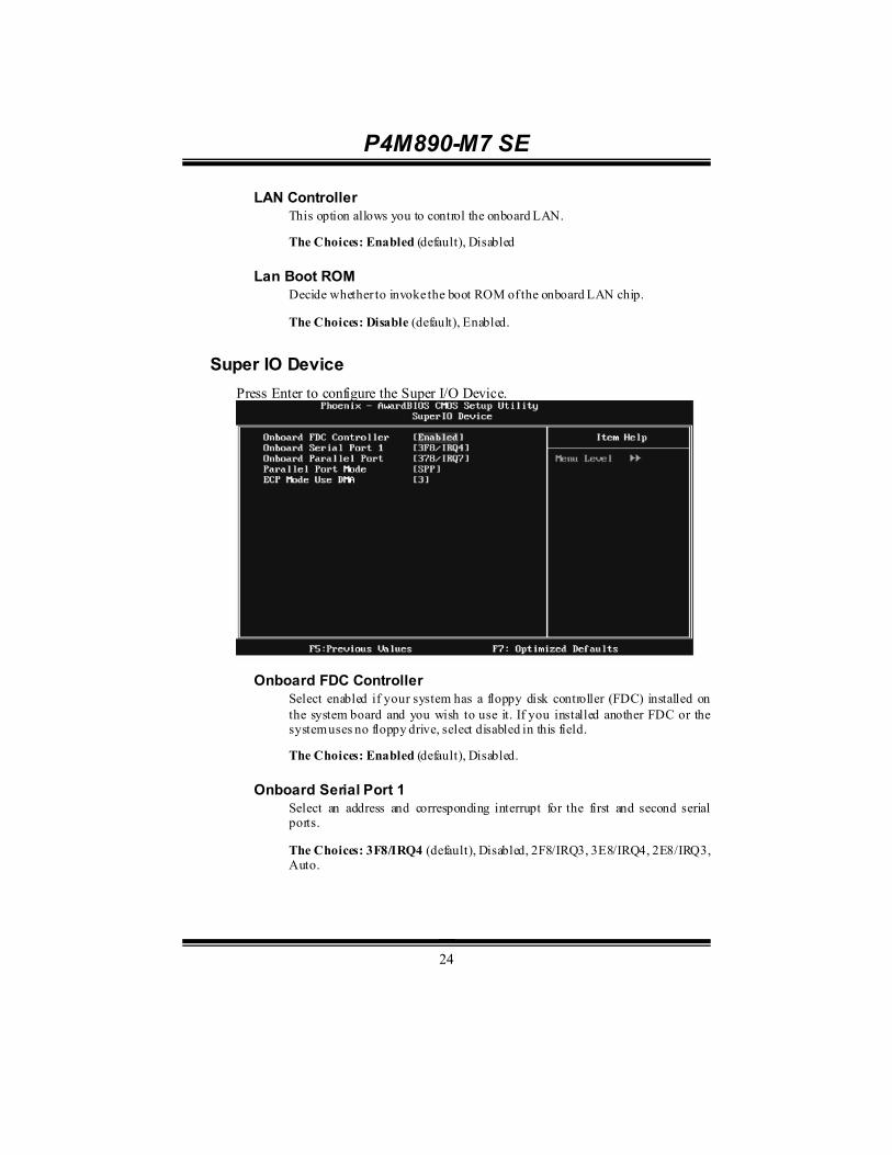
P4M890-M7 SE
24
LAN Controller This option allows you to control the onboard LAN.
The Choices: Enabled (default), Disabled
Lan Boot ROM Decide whether to invoke the boot ROM of the onboard LAN chip.
The Choices: Disable (default), Enabled.
Super IO Device Press Enter to configure the Super I/O Device.
Onboard FDC Controller
Select enabled if your system has a floppy disk controller (FDC) installed on the system board and you wish to use it. If you installed another FDC or the system uses no floppy drive, select disabled in this field.
The Choices: Enabled (default), Disabled.
Onboard Serial Port 1 Select an address and corresponding interrupt for the first and second serial ports.
The Choices: 3F8/IRQ4 (default), Disabled, 2F8/IRQ3, 3E8/IRQ4, 2E8/IRQ3, Auto.

P4M890-M7 SE
25
Onboard Parallel Port This item allows you to determine access onboard parallel port controller with which I/O Address.
The Choices: 378/IRQ7 (default), 278/IRQ5, 3BC/IRQ7, Disabled.
Parallel Port Mode This item allows you to determine how the parallel port should function. The default value is SPP.
The Choices:
SPP (default) Using Parallel port as Standard Printer Port.
EPP Using Parallel Port as Enhanced Parallel Port.
ECP Using Parallel port as Extended Capabilities Port.
ECP+EPP Using Parallel port as ECP & EPP mode.
ECP Mode Use DMA Select a DMA Channel for the port.
The Choices: 3 (default), 1.
USB Device Setting Press Enter to configure the USB Device.

P4M890-M7 SE
26
USB 1.0/2.0 Controller These options allow you to enable or disable the USB 1.0/2.0 controller function.
The Choices: Enabled (default), Disabled.
USB Operation Mode This option let you select the operation mode of USB function.
The Choices: High Speed (default), Full/Low Speed.
USB Keyboard/Mouse/Storage Function These options allow you to enable or disable the USB keyboard/mouse/storage devices.
The Choices: Enabled (default), Disabled.
USB Mass Storage Dev ice Boot Setting These options allow you to choose the boot up type of the USB mass storage devices..
The Choices: Auto mode (default), FDD mode, HDD mode.
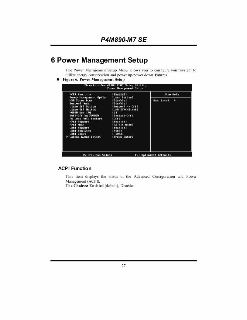
P4M890-M7 SE
27
6 Power Management Setup The Power Management Setup Menu allows you to configure your system to utilize energy conservation and power up/power down features.
Figure 6. Power Management Setup
ACPI Function This item displays the status of the Advanced Configuration and Power Management (ACPI). The Choices: Enabled (default), Disabled.

P4M890-M7 SE
28
Power Management This category allows you to select the power saving method and is directly related to the following modes: 1. HDD Power Down. 2. Suspend Mode. There are three options of Power Management, three of which have fixed mode settings Min. Power Saving
Minimum power management. Suspend Mode = 1 hr. HDD Power Down = 15 min Max. Power Saving
Maximum power management only available for sl CPU’s. Suspend Mode = 1 min. HDD Power Down = 1 min. User Define (default)
Allow you to set each option individually. When you choose user define, you can adjust each of the item from 1 min. to 1 hr. except for HDD Power Down which ranges from 1 min. to 15 min.
HDD Power Down When enabled, the hard-disk drives will power down after a set time of system inactivity. All other devices remain active. The Choices: Disabled (default), 1 Min, 2 Min, 3 Min, 4 Min, 5 Min, 6 Min, 7 Min, 8 Min, 9 Min, 10 Min, 11 Min, 12 Min, 13 Min, 14 Min, 15Min.
Suspend Mode The item allows you to adjust the system idle time before suspend. The Choices: Disabled (default), 1 Min, 2 Min, 4 Min, 6 Min, 8 Min, 10 Min, 20 Min, 30 Min, 40 Min, 1 Hour.
Video Off Option This field determines when to activate the video off feature for monitor power management. The Choices: Suspend→Off (default), Always on.

P4M890-M7 SE
29
Video Off Method This option determines the manner when the monitor goes blank. V/H SYNC+Blank (default)
This selection will cause the system to turn off the vertical and horizontal synchronization ports and write blanks to the video buffer. Blank Screen This option only writes blanks to the video buffer. DPMS Initial display power management signaling.
Modem Use IRQ This determines the IRQ, which can be applied in MODEM use. The Choices: 3 (default), 4, 5, 7, 9, 10, 11, NA.
Soft-Off by PWRBTN This item determines the behavior of system power button. Instant off turn off the power immediately, and Delay 4 Sec. will require you to press and hold the power button for 4 seconds to cut off the system power. The Choices: Delay 4 Sec, Instant-Off (default).
Ac Loss Auto Restart This setting specifies how your system should behave aft er a power fail or interrupts occurs. By choosing off will leave the computer in the power off stat e. Choosing On will reboot the computer. Former-Sts will restore the system to the status before power failure or interrupt occurs. The Choices: Off (default), On, Former-Sts.
HPET Support This option allows you to disabled or enables the High Precision Event Timer. The Choices: Enabled (default), Disabled.
HPET Mode This option allows you to select the modes of the High Precision Event Timer. The Choices: 32-bit mode (default), 64-bit mode.
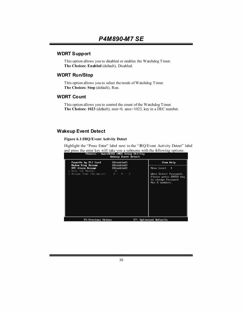
P4M890-M7 SE
30
WDRT Support This option allows you to disabled or enables the Watchdog Timer. The Choices: Enabled (default), Disabled.
WDRT Run/Stop This option allows you to select the mode of Watchdog Timer. The Choices: Stop (default), Run.
WDRT Count This option allows you to control the count of the Watchdog Timer. The Choices: 1023 (default); min=0, amx=1023, key in a DEC number.
Wakeup Event Detect Figure 6.1:IRQ/Event Activity Detect
Highlight the “Press Enter” label next to the “ IRQ/Event Activity Detect” label and press the enter key will take you a submenu with the following options:

P4M890-M7 SE
31
PowerOn by PCI Card When you select Enabled, a PME signal from PCI card returns the system to Full ON state.
For this function to work, you may need a LAN add-on card which supports the Wake on LAN function. Set the Wake on LAN (WOL) jumper on motherboard to enable if applicable.
The Choices: Disabled (default), Enabled.
Modem Ring Resume This item allows you to disable or enable Modem Ring Resume function.
The Choices: Disabled (default), Enabled.
RTC Alarm Resume When “Enabled”, you can set the date and time at which the RTC (real-time clock) alarm awakens the system fro m Suspend mode.
The Choices: Disabled (default), Enabled.
Date (of Month) You can choose which month the system will boot up. This field is only configurable when “RTC Resume” is set to “Enabled”.
Resume Time (hh:mm:ss) You can choose the hour, minute and second the system will boot up. This field is only configurable when “RTC Resume” is set to “Enabled”.

P4M890-M7 SE
32
7 PnP/PCI Configurations This section describes configuring the PCI bus system. PCI, or Personal Computer Interconnect, is a system which allows I/O devices to operate at speeds nearing the speed of the CPU itself uses when communicating with its own special components. This section covers some very technical items and it is strongly recommended that only experienced users should make any changes to the default settings.
Figure 7: PnP/PCI Configurations
PNP OS Installed When set to YES, BIOS will only initialize the PnP cards used for the boot sequence (VGA, IDE, SCSI). The rest of the cards will be initialized by the PnP operating system like Window™ 95. When set to NO, BIOS will initialize all the PnP cards. For non-PnP operating systems (DOS, Netware™), this option must set to NO. The Choices: No (default), Yes.
Init Display First This item allows you to decide to active whether PCI Slot or on-chip VGA first. The Choices: PCIEx (default), PCI Slot, Onboard, AGP.
P4M890-M7 SE
33
Reset Configuration Data The system BIOS supports the PnP feature which requires the system to record which resources are assigned and protects resources from conflict. Every peripheral device has a node, which is called ESCD. This node records which resources are assigned to it. The system needs to record and update ESCD to the memory locations. These locations are reserved in the system BIOS. If the Disabled (default) option is chosen, the system‘s ESCD will update only when the new configuration varies from the last one. If the Enabled option is chosen, the system is forced to update ESCDs and then is automatically set to the “ Disabled” mode. The above settings will be shown on the screen only if “ Manual” is chosen for the resources controlled by function. Legacy is the term, which signifies that a resource is assigned to the ISA Bus and provides non-PnP ISA add-on cards. PCI / ISA PnP signify that a resource is assigned to the PCI Bus or provides for ISA PnP add-on cards and peripherals. The Choices: Disabled (default), Enabled.
Resources Controlled By By Choosing “Auto(ESCD)” (default), the system BIOS will detect the system resources and automatically assign the relative IRQ and DMA channel for each peripheral. By Choosing “Manual”, the user will need to assign IRQ & DMA for add-on cards. Be sure that there are no IRQ/DMA and I/O port conflicts. The Choices: Auto (ESCD) (default), Manual.

P4M890-M7 SE
34
IRQ Resources This submenu will allow you to assign each system interrupt a type, depending on the type of device using the interrupt. When you press the “ Press Enter” tag, you will be directed to a submenu that will allow you to configure the system interrupts. This is only configurable when “ Resources Controlled By” is set to “Manual”. IRQ-3 assigned to PCI Device IRQ-4 assigned to PCI Device IRQ-5 assigned to PCI Device IRQ-7 assigned to PCI Device IRQ-9 assigned to PCI Device IRQ-10 assigned to PCI Device IRQ-11 assigned to PCI Device IRQ-12 assigned to PCI Device IRQ-14 assigned to PCI Device IRQ-15 assigned to PCI Device
PCI / VGA Palette Snoop Some old graphic controllers need to “ snoop” on the VGA palette and then map it to their display as a way to provide boot information and VGA compatibility. This item allows such snooping to take place. The Choices: Disabled (default), Enabled
Assign IRQ For VGA This item allows the users to choose which IRQ to assign for the VGA. The Choices: Enabled (default), Disabled.
Assign IRQ For USB This item allows the users to choose which IRQ to assign for the USB. The Choices: Enabled (default), Disabled.
Maximum Payload Size Set the maximum payload size for Transaction packets (TLP). The Choice: 4096 (default.), 128, 256, 512, 1024, 2048.
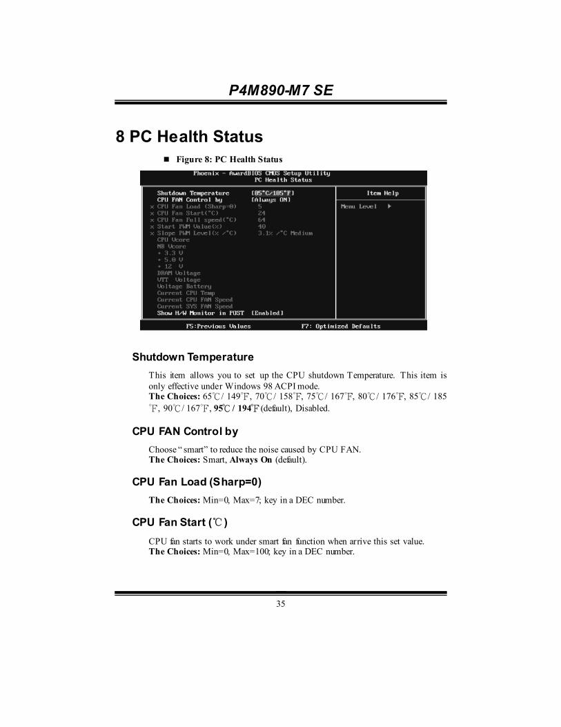
P4M890-M7 SE
35
8 PC Health Status Figure 8: PC Health Status
Shutdown Temperature This item allows you to set up the CPU shutdown Temperature. This item is only effective under Windows 98 ACPI mode. The Choices: 65℃/ 149℉, 70℃/ 158℉, 75℃/ 167℉, 80℃/ 176℉, 85℃/ 185℉, 90℃/ 167℉, 95℃ / 194℉ (default), Disabled.
CPU FAN Control by Choose “ smart” to reduce the noise caused by CPU FAN. The Choices: Smart, Always On (default).
CPU Fan Load (Sharp=0) The Choices: Min=0, Max=7; key in a DEC number.
CPU Fan Start (℃) CPU fan starts to work under smart fan function when arrive this set value. The Choices: Min=0, Max=100; key in a DEC number.

P4M890-M7 SE
36
CPU Fan Full speed <℃> When CPU temperature is reach the set value, the CPU fan will work under Full Speed. The Choices: Min=0, Max=100; key in a DEC number.
Start PWM Value (%) When CPU temperature arrives to the set value, the CPU fan will work under Smart Fan Function mode. The range is from 0~127, with an interval of 1. The Choices: Min=0, Max=100; key in a DEC number.
Slope PWM Level (%/℃) Increasing the value of slope PWM will raise the speed of CPU fan. The Choices: 3.1%/℃ Medium(default), 0.0%/℃, 0.8%/℃, 1.6%/℃,6.3%/℃
High,12.5%/℃, 25.0%/℃, 50.0%/℃.
CPU Vcore, NB Vcore, +3.3V, +5.0V, +12V, DRAM Voltage, VTT Voltage, Voltage Battery
Detect the system’s voltage status automatically.
Current CPU Temp This field displays the current temperature of CPU.
Current CPU FAN Speed This field displays the current speed of CPU fan.
Current SYS FAN Speed This field displays the current speed SYSTEM fan.
Show H/W Monitor in POST If you computer contains a monitoring system, it will show PC health status during POST stage. The item offers several different delay times. The Choices: Enabled (default), Disabled.

P4M890-M7 SE
37
9 Performance Booster Zone Figure 9: Performance Booster Zone
DRAM Clock/Drive Control This item controls the DRAM Clock. Highlight “Press Enter” next to the “ DRAM Clock/Drive Control” label and pressing the enter key will take you a submenu with the following options:
Figure 9.1: DRAM Clock/Drive Control

P4M890-M7 SE
38
DRAM Clock This item determines DRAM clock.
The Choices: By SPD (default), 100MHz, 133MHz, 166MHz, 200MHz, 266MHz, 333MHz .
DRAM Timing This item determines DRAM clock/ timing.
The Choices: Auto by SPD (default), Manual, Turbo, Ultra.
SDRAM CAS Latency When DRAM is installed, the number of clock cycles of CAS latency depends on the DRAM timing.
The Choices: 2.5 /4(default).
Bank Interleave This item allows you to enable or disable the bank interleave feature.
The Choices: Disabled (default).
Precharge to Active (tRP) This item allows you to specify the delay from precharge command to activate command.
The Choices: 4T (default).
Activ e to Precharge (tRAS) This item allows you to specify the minimum row active time (tRAS).
The Choices: 07T (default).
Activ e to CMD (tRCD) Use this item to specify the delay from the activation of a bank to the time that a read or write command is accepted.
The Choices: 4T (default).
REF to ACT/REF to REF (Trfc) This item allows you to determine the selection for REF to ACT/REF to REF (tRFC).
The Choices: 20T/21T (default).

P4M890-M7 SE
39
ACT (0) to ACT (1) (tRRD) This item allows you to determine the selection for ACT (0) to ACT (1) (tRRD)
The Choices: 3T (default).
1T CMD Support The Choices: Disable (default), Auto.
DDR2 On Die Termination This option allows you to choose the working type of ODT.
The Choices: ODT Always ON (default), Dynamic ODT, ODT Always OFF.
CPU CLOCK This item allows you to select CPU Clock, and CPU over clocking. Special Notice: If the system’s frequency that you are selected is not functioning, there are two methods of booting-up the system. Method 1: Clear the COMS data by setting the JCOMS1 ((2-3) closed)) as “ ON” status. All the CMOS data will be loaded as defaults setting. Method 2: Press the <Insert> key and Power button simultaneously, after that keep-on pressing the <Insert> key until the power-on screen showed. This action will boot-up the system according to FSB of the processor It’s strongly recommended to set CPU Vcore and clock in default setting. If the CPU Vcore and clock are not in default setting, it may cause CPU or M/B damage. The Choices: 100MHz(default); Min=100, Max=400, key in a DEC number.
Async PCIE CLOCK This item allows you to select Async PCIE clock. Min= 100 Max=150 Key in a DEC number. The Choices: 100MHz(default) ; Min=100, Max=150, key in a DEC number.
CPU Clock Ratio This item allows you to select the CPU Ratio. Min= 6 Max= 50 Key in a DEC number. The Choices: 6X (default).
P4M890-M7 SE
40
Spread Spectrum This item allows you to enable/disable the Spread Spectrum function. The Choices:+/- 0.25% (default), +/- 0. 5%, Disabled, -0.5%, -1.0%.
DDR Voltage This item allows you to select DDR Voltage. The Choices: StartUp (default), +0.10V, +0.20V, +0.30V, +0.40V, +0.50V, +0.60V, +0.70V.
CPU Voltage This item allows you to select CPU Voltage. The Choices: StartUp (default), +0.012V~+0.787V.

P4M890-M7 SE BIOS Setup
i
BIOS Setup.................................................................................................1
1 Main Menu...............................................................................................3
2 Standard CMOS Features......................................................................7
3 Advanced BIOS Features .......................................................................9
4 Advanced Chipset Features..................................................................17
5 Integrated Peripherals..........................................................................21
6 Power Management Setup....................................................................27
7 PnP/PCI Configurations.......................................................................32
8 PC Health Status ...................................................................................35
9 Performance Booster Zone...................................................................37
P4M890-M7 SE
1
BIOS Setup
Introduction The purpose of this manual is to describe the settings in the Phoenix-Award™ BIOS Setup program on this motherboard. The Setup program allows users to modify the basic system configuration and save these settings to CMOS RAM. The power of CMOS RAM is supplied by a battery so that it retains the Setup information when the power is turned off. Basic Input-Output System (BIOS) determines what a computer can do without accessing programs from a disk. This system controls most of the input and output devices such as keyboard, mouse, serial ports and disk drives. BIOS activates at the first stage of the booting process, loading and executing the operating system. Some additional features, such as virus and password protection or chipset fine-tuning options are also included in BIOS. The rest of this manual will to guide you through the options and settings in BIOS Setup.
Plug and Play Support This PHOENIX-AWARD BIOS supports the Plug and Play Version 1.0A speci fication and ESCD (Extended System Configuration Data) write.
EPA Green PC Support This PHOENIX-AWARD BIOS supports Version 1.03 of the EPA Green PC speci fication.
APM Support This PHOENIX-AWARD BIOS supports Version 1.1&1.2 of the Advanced Power Management (APM) speci fication. Power management features are implemented via the System Management Interrupt (SMI). Sleep and Suspend power management modes are supported. Power to the hard disk drives and video monitors can also be managed by this PHOENIX-AWARD BIOS.
P4M890-M7 SE
2
ACPI Support Phoenix-Award ACPI BIOS support Version 1.0b of Advanced Configuration and Power interface speci fi cation (ACPI). It provides ASL code for power management and device configuration capabilities as defined in the ACPI speci fication, developed by Microsoft, Intel and Toshiba.
PCI Bus Support This PHOENIX-AWARD BIOS also supports Version 3.0 of the Int el PCI (Peripheral Component Interconnect) local bus specification.
DRAM Support DDR SDRAM (Double Data Rate Synchronous DRAM) is supported.
Supported CPUs This PHOENIX-AWARD BIOS supports the Intel CPU.
Using Setup Use the arrow keys to highlight items in most of the place, press <Enter> to select, use the <PgUp> and <PgDn> keys to change entries, press <F1> for help and press <Esc> to quit. The following table provides more detail about how to navigate in the Setup program by using the keyboard.
Keystroke Function Up arrow Move to previous item Down arrow Move to next item Left arrow Move to the item on the left (menu bar) Right arrow Move to the item on the right (menu bar) Move Enter Move to the item you desired PgUp key Increase the numeric val ue or make changes PgDn key Decrease the numeric value or make changes + Key Increase the numeric val ue or make changes - Key Decrease the numeric value or make changes Esc key Main Menu – Quit and not save changes into CMOS
Status Page Setup Menu and Option Page Setup Menu – Exit Current page and r eturn to M ain Menu
F1 key General help on Setup navigation keys F5 key Load pr evious values from CMOS F7 key Load the opti mized defaults F10 key Save all the CMOS changes and exit
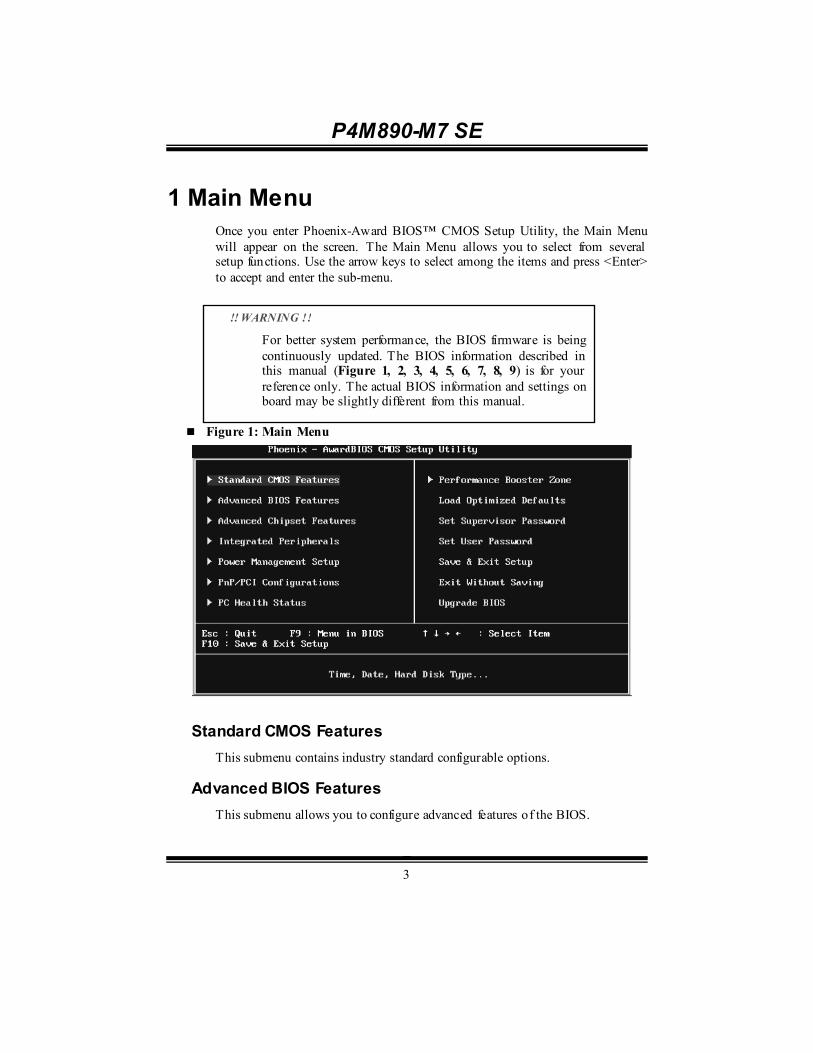
P4M890-M7 SE
3
1 Main Menu Once you enter Phoenix-Award BIOS™ CMOS Setup Utility, the Main Menu will appear on the screen. The Main Menu allows you to select from several setup functions. Use the arrow keys to select among the items and press <Enter> to accept and enter the sub-menu.
Figure 1: Main Menu
Standard CMOS Features This submenu contains industry standard configurable options.
Advanced BIOS Features This submenu allows you to configure advanced features of the BIOS.
!! WARNING !!
For better system performance, the BIOS firmware is being continuously updated. The BIOS information described in this manual (Figure 1, 2, 3, 4, 5, 6, 7, 8, 9) is for your reference only. The actual BIOS information and settings on board may be slightly different from this manual.
P4M890-M7 SE
4
Advanced Chipset Features This submenu allows you to configure special chipset features.
Integrated Peripherals This submenu allows you to configure cert ain IDE hard drive options and Programmed Input/ Output features.
Power Management Setup This submenu allows you to configure the power management features.
PnP/PCI Configurations This submenu allows you to configure cert ain “ Plug and Play” and PCI options.
PC Health Status This submenu allows you to monitor the hardware of your system.
Performance Booster Zone This submenu allows you to change CPU Vcore Voltage and CPU/PCI clock. (However, we suggest you to use the default setting. Changing the voltage and clock improperly may damage the CPU or M/B!)
Load Optimized Defaults This selection allows you to reload the BIOS when problem occurs during system booting sequence. These configurations are factory settings optimized for this system. A confirmation message will be displayed before defaults are set.
P4M890-M7 SE
5
Set Supervisor Password Setting the supervisor password will prohibit everyone except the supervisor from making changes using the CMOS Setup Utility. You will be prompted with to enter a password.
Set User Password If the Supervisor Password is not set, then the User Password will function in the same way as the Supervisor Password. If the Supervisor Password is set and the User Password is set, the “User” will only be able to view configurations but will not be able to change them.
Save & Exit Setup Save all configuration changes to CMOS (memory) and exit setup. Confirmation message will be displayed before proceeding.
Exit Without Saving Abandon all changes made during the current session and exit setup. Confirmation message will be displayed before proceeding.

P4M890-M7 SE
6
Upgrade BIOS This submenu allows you to upgrade bios.

P4M890-M7 SE
7
2 Standard CMOS Features The items in Standard CMOS Setup Menu are divided into several categori es. Each category includes no, one or more than one setup items. Use the arrow keys to highlight the item and then use the<PgUp> or <PgDn> keys to select the value you want in each item.
Figure 2: Standard CMOS Setup
Main Menu Selections
This table shows the items and the available options on the Main Menu.
Item Options Description
Date mm : dd : yy
Set the system date. Note that the ‘Day ’ automatically changes when you set the date.
Time hh : mm : ss Set the system internal clock.
IDE Channel 0 Master Options are in its sub menu.
Press <Enter> to enter the sub menu of detailed options
IDE Channel 0 Slav e Options are in its sub menu.
Press <Enter> to enter the sub menu of detailed options.
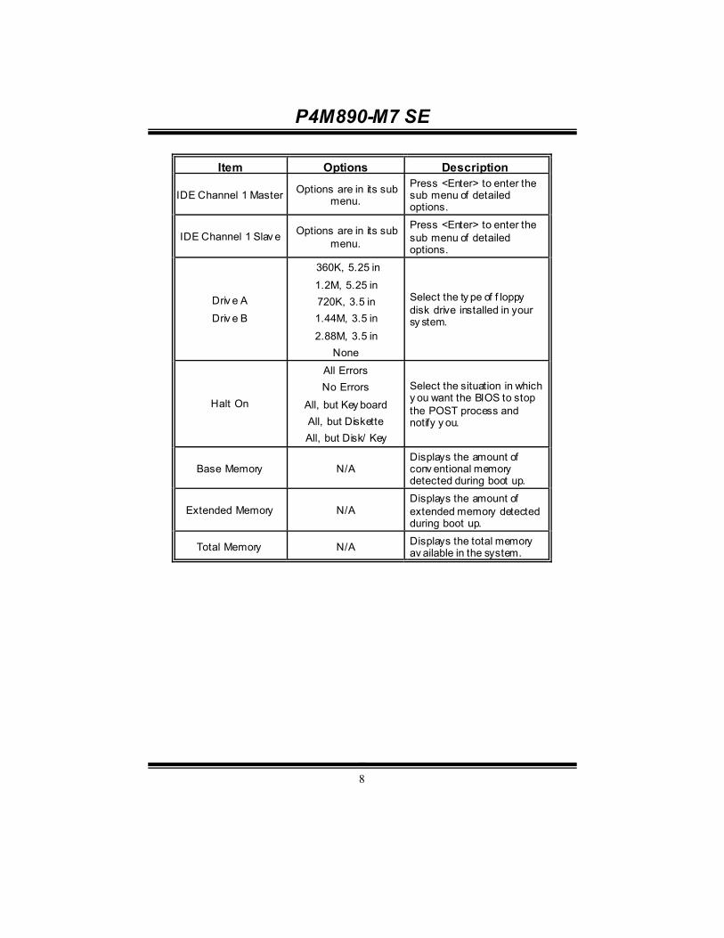
P4M890-M7 SE
8
Item Options Description
IDE Channel 1 Master Options are in its sub menu.
Press <Enter> to enter the sub menu of detailed options.
IDE Channel 1 Slav e Options are in its sub menu.
Press <Enter> to enter the sub menu of detailed options.
Driv e A
Driv e B
360K, 5.25 in
1.2M, 5.25 in 720K, 3.5 in 1.44M, 3.5 in
2.88M, 3.5 in None
Select the ty pe of f loppy disk drive installed in your sy stem.
Halt On
All Errors No Errors
All, but Key board All, but Diskette All, but Disk/ Key
Select the situation in which y ou want the BIOS to stop the POST process and notify y ou.
Base Memory N/A Displays the amount of conv entional memory detected during boot up.
Extended Memory N/A Displays the amount of extended memory detected during boot up.
Total Memory N/A Displays the total memory av ailable in the system.

P4M890-M7 SE
9
3 Advanced BIOS Features Figure 3: Advanced BIOS Setup
Boot Seq & Floppy Setup This item allows you to setup boot sequence & Floppy.
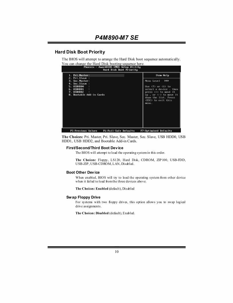
P4M890-M7 SE
10
Hard Disk Boot Priority The BIOS will attempt to arrange the Hard Disk boot sequence automatically. You can change the Hard Disk booting sequence here.
The Choices: Pri. Master, Pri. Slave, Sec. Master, Sec. Slave, USB HDD0, USB HDD1, USB HDD2, and Bootable Add-in Cards.
First/Second/Third Boot Dev ice The BIOS will attempt to load the operating system in this order.
The Choices: Floppy, LS120, Hard Disk, CDROM, ZIP100, USB-FDD, USB-ZIP, USB-CDROM, LAN, Disabled.
Boot Other Dev ice When enabled, BIOS will try to load the operating system from other device when it failed to load from the three devices above.
The Choices: Enabled (default), Disabled
Swap Floppy Drive For systems with two floppy drives, this option allows you to swap logical drive assignments.
The Choices: Disabled (default), Enabled.

P4M890-M7 SE
11
Boot Up Floppy Seek When enabled, System will test the floppy drives to determine if they have 40 or 80 tracks during boot up. Disabling this option reduces the time it takes to boot-up.
The Choices: Enabled (default), Disabled.
Shadow Setup This item allows you to setup cache & shadow setup.
Figure 3.2: Shadow Setup
Video BIOS Shadow
Determines whether video BIOS will be copied to RAM for faster execution or not.
Enabled (default) Optional ROM is enabled.
Disabled Optional ROM is disabled.

P4M890-M7 SE
12
Cache Setup
CPU L1 & L2 Cache Depending on the CPU/chipset in use, you may be able to increase memory access time with this option.
Enabled (default) Enable cache.
Disabled Disable cache.
CPU L3 Cache Depending on the CPU/chipset in use, you may be able to increase memory access time with this option.
Enabled (default) Enable cache.
Disabled Disable cache.
CPU L2 Cache ECC Checking This item allows you to enable/disable CPU L2 Cache ECC Checking.
The Choices: Enabled (default), Disabled.
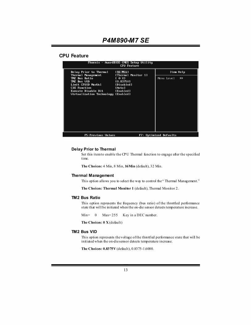
P4M890-M7 SE
13
CPU Feature
Delay Prior to Thermal
Set this item to enable the CPU Thermal function to engage after the specified time.
The Choices: 4 Min, 8 Min, 16Min (default), 32 Min.
Thermal Management This option allows you to select the way to control the “ Thermal Management.”
The Choices: Thermal Monitor 1 (default), Thermal Monitor 2.
TM2 Bus Ratio This option represents the frequency (bus ratio) of the throttled performance state that will be initiated when the on-die sensor detects temperature increase.
Min= 0 Max= 255 Key in a DEC number.
The Choices: 0 X (default)
TM2 Bus VID This option represents the voltage of the throttled performance state that will be initiated when the on-die sensor detects temperature increase.
The Choices: 0.8375V (default), 0.8375-1.6000.
P4M890-M7 SE
14
Limit CPUID MaxVal Set Limit CPUID MaxVal to 3, it should be “Disabled” for Windows XP.
The Choices: Disabled (default), Enabled.
C1E Function This item allows you to configure the Enhanced Halt State (C1E) function, which may reduce the power consumption of your system when the system is idle.
The Choices: Auto (default),Disabled.
Execute Disable Bit This item allows you to configure the Execute Disabled Bit function, which protects your system from buffer overflow attacks.
The Choices: Enabled (default), Disabled.
Virtualization Technology Virtualization Technology can virtually separate your system resource into several parts, thus enhance the performance when running virtual machines or multi interface systems.
The Choices: Enabled (default), Disabled.
Virus Warning This option allows you to choose the VIRUS Warning feature that is used to protect the IDE Hard Disk boot sector. If this function is enabled and an attempt is made to write to the boot sector, BIOS will display a warning message on the screen and sound an alarm beep. Disabled (default) Virus protection is disabled. Enabled Virus protection is activated.
Hyper-Threading Technology This option allows you to enable or disabled Hyper-Threading Technology. “ Enabled” for Windows XP and Linux 2.4.x (OS optimized for Hyper-Threading Technology). “ Disable” for other OS (OS not optimized for Hyper-Threading Technology). The Choices: Enabled (default), Disabled.

P4M890-M7 SE
15
Quick Power On Self Test Enabling this option will cause an abridged version of the Power On Self-Test (POST) to execute after you power up the computer. Disabled Normal POST. Enabled (default) Enable quick POST.
Boot Up NumLock Status Selects the NumLock State after the system switched on. The Choices: On (default) Numpad is number keys. Off Numpad is arrow keys.
Typematic Rate Setting When a key is held down, the keystroke will repeat at a rate determined by the keyboard controller. When enabled, the typematic rate and typematic delay can be configured. The Choices: Disabled (default), Enabled.
Typematic Rate (Chars/Sec) Sets the rate at which a keystroke is repeated when you hold the key down. The Choices: 6 (default), 8, 10, 12, 15, 20, 24, 30.
Typematic Delay (Msec) Sets the delay time after the key is held down before it begins to repeat the keystroke. The Choices: 250 (default), 500, 750, 1000.
Security Option This option will enable only individuals with passwords to bring the system online and/or to use the CMOS Setup Utility. System: A password is required for the system to boot and is also required to access the Setup Utility. Setup (default): A password is required to access the Setup Utility only. This will only apply if passwords are set from the Setup main menu.

P4M890-M7 SE
16
MPS Version Control For OS The BIOS supports version 1.1 and 1.4 of the Intel multiprocessor speci fication. Select version supported by the operation system running on this computer. The Choices: 1.4 (default), 1.1.
OS Select For DRAM > 64MB A choice other than Non-OS2 is only used for OS2 systems with memory exceeding 64MB. The Choices: Non-OS2 (default), OS2.
HDD S.M.A.R.T. Capability This item allows you to enable/disable HDD S.M.A.R.T. Capability. The Choices: Disabled (default), Enabled.
Small Logo(EPA) Show This item allows you to select whether the “Small Logo” shows. Enabled (default) “ Small Logo” shows when system boots up. Disabled No “Small Logo” shows when system boots The Choices: Enabled (default), Disabled
Summary Screen Show This item allows you to enable/disable the summary screen. Summary screen means system configuration and PCI device listing. The Choices: Disabled (default), Enabled.

P4M890-M7 SE
17
4 Advanced Chipset Features This submenu allows you to configure the speci fic features of the chipset installed on your system. This chipset manage bus speeds and access to system memory resources, such as DRAM. It also coordinates communications with the PCI bus. The default settings that came with your system have been optimized and therefore should not be changed unless you are suspicious that the settings have been changed incorrectly.
Figure 4: Advanced Chipset Setup

P4M890-M7 SE
18
AGP & P2P Bridge Control Highlight “Press Enter” next to the “ AGP & P2P Bridge Control” label and pressing the enter key will take you a submenu with the following options:
Figure 4.1: AGP & P2P Bridge Control
AGP Aperture Size
Select the size of the Accelerated Graphics Port (AGP) aperture. The aperture is a portion of the PCI memory address range dedicated for graphics memory address space. Host cycles that hit the aperture range are forwarded to the AGP without the need of translation. The Choices: 32M, 64M, 128M (default), 256M.
AGP 2.0 Mode This item allows you to select the AGP Mode. The Choices: 8X (default), 4X.
AGP Master 1 WS Write When enabled, writes to the AGP (Accelerated Graphics Port) are executed with one wait states.
The Choices: Enabled (default), Disabled.
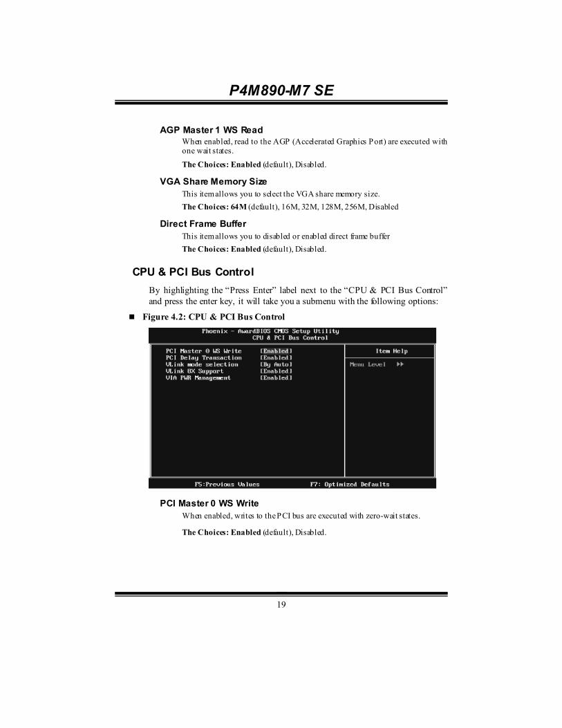
P4M890-M7 SE
19
AGP Master 1 WS Read When enabled, read to the AGP (Accelerated Graphics Port) are executed with one wait states.
The Choices: Enabled (default), Disabled.
VGA Share Memory Size This item allows you to select the VGA share memory size. The Choices: 64M (default), 16M, 32M, 128M, 256M, Disabled
Direct Frame Buffer This item allows you to disabled or enabled direct frame buffer The Choices: Enabled (default), Disabled.
CPU & PCI Bus Control By highlighting the “Press Enter” label next to the “CPU & PCI Bus Control” and press the enter key, it will take you a submenu with the following options:
Figure 4.2: CPU & PCI Bus Control
PCI Master 0 WS Write
When enabled, writes to the PCI bus are executed with zero-wait states.
The Choices: Enabled (default), Disabled.
P4M890-M7 SE
20
PCI Delay Transaction The chipset has an embedded 32-bit posted write buffer to support delay transactions cycles. Select Enabled to support compliance with PCI specification.
The Choices: Enabled (default), Disabled.
Vlink mode selection This item allows you to select Vlink mode.
The Choices: By Auto (default), Mode 0 , Mode 1.
VLink 8X Support This item allows you to enable or disable VLink 8X support.
The Choices: Enabled (default), Disabled.
VIA PWR Management The Choices: Enabled (default), Disabled.
Memory Hole You can reserve this area of system memory for ISA adapter ROM. When this area is reserved it cannot be cached. Check the user information of peripherals that need to use this area of system memory for the memory requirements. The Choices: Disabled (default), Enabled.
System BIOS Cacheable Selecting the “ Enabled” option allows caching of the system BIOS ROM at F0000h-FFFFFh, which is able to improve the system performance. However, any programs that attempts to write to this memory block will cause conflicts and result in system errors. The Choices: Enabled (default), Disabled.
Top Performance The Choices: Disabled (default), Enabled.
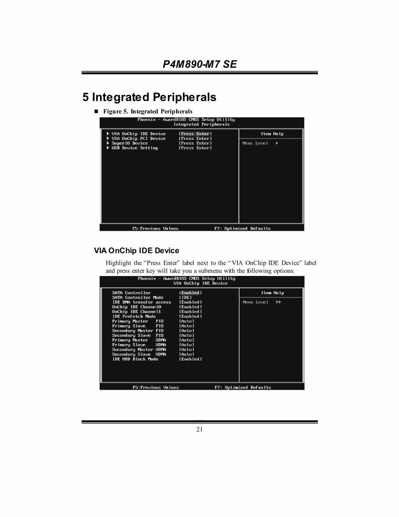
P4M890-M7 SE
21
5 Integrated Peripherals Figure 5. Integrated Peripherals
VIA OnChip IDE Device Highlight the “Press Enter” label next to the “ VIA OnChip IDE Device” label and press enter key will take you a submenu with the following options:

P4M890-M7 SE
22
SATA Controller This option allows you to enable the on-chip Serial ATA.
The Choices: Enabled (default), Disabled.
SATA Controller Mode This option allows you to select SATA Mode.
The Choices: RAID, IDE (default).
IDE DMA Transfer Access This item allows you to enable or disable the IDE DMA transfer access.
The Choices: Enabled (default), Disabled.
On-chip IDE Channel 0/1 The motherboard chipset contains a PCI IDE interface with support for two IDE channels. Select “Enabled” to activate the first and/or second IDE interface. Select “Disabled” to deactivate an interface if you are going to install a primary and/or secondary add-in IDE interface.
The Choices: Enabled (default), Disabled.
IDE Prefetch Mode The “ onboard” IDE drive interfaces supports IDE prefetch function for faster drive access. If the interface on your drive does not support prefetching, or if you install a primary and/or secondary add-in IDE interface, set this option to “Disabled”.
The Choices: Enabled (default), Disabled.
Primary/Secondary/Master/Slave PIO The IDE PIO (Programmed Input / Output) fields let you set a PIO mode (0-4) for each of the IDE devices that the onboard IDE interface supports. Modes 0 to 4 will increase performance progressively. In Auto mode, the system automatically determines the best mode for each device.
The Choices: Auto (default), Mode0, Mode1, Mode2, Mode3, Mode4.
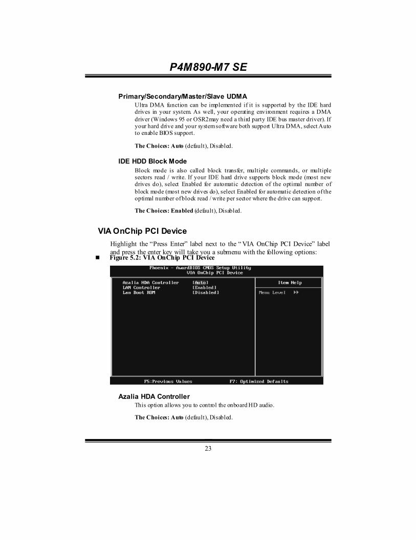
P4M890-M7 SE
23
Primary/Secondary/Master/Slave UDMA Ultra DMA function can be implemented if it is supported by the IDE hard drives in your system. As well, your operating environment requires a DMA driver (Windows 95 or OSR2may need a third party IDE bus master driver). If your hard drive and your system software both support Ultra DMA, select Auto to enable BIOS support.
The Choices: Auto (default), Disabled.
IDE HDD Block Mode Block mode is also called block transfer, multiple commands, or multiple sectors read / write. If your IDE hard drive supports block mode (most new drives do), select Enabled for automatic detection of the optimal number of block mode (most new drives do), select Enabled for automatic detection of the optimal number of block read / write per sector where the drive can support.
The Choices: Enabled (default), Disabled.
VIA OnChip PCI Device Highlight the “Press Enter” label next to the “ VIA OnChip PCI Device” label and press the enter key will take you a submenu with the following options:
Figure 5.2: VIA OnChip PCI Device
Azalia HDA Controller
This option allows you to control the onboard HD audio.
The Choices: Auto (default), Disabled.

P4M890-M7 SE
24
LAN Controller This option allows you to control the onboard LAN.
The Choices: Enabled (default), Disabled
Lan Boot ROM Decide whether to invoke the boot ROM of the onboard LAN chip.
The Choices: Disable (default), Enabled.
Super IO Device Press Enter to configure the Super I/O Device.
Onboard FDC Controller
Select enabled if your system has a floppy disk controller (FDC) installed on the system board and you wish to use it. If you installed another FDC or the system uses no floppy drive, select disabled in this field.
The Choices: Enabled (default), Disabled.
Onboard Serial Port 1 Select an address and corresponding interrupt for the first and second serial ports.
The Choices: 3F8/IRQ4 (default), Disabled, 2F8/IRQ3, 3E8/IRQ4, 2E8/IRQ3, Auto.

P4M890-M7 SE
25
Onboard Parallel Port This item allows you to determine access onboard parallel port controller with which I/O Address.
The Choices: 378/IRQ7 (default), 278/IRQ5, 3BC/IRQ7, Disabled.
Parallel Port Mode This item allows you to determine how the parallel port should function. The default value is SPP.
The Choices:
SPP (default) Using Parallel port as Standard Printer Port.
EPP Using Parallel Port as Enhanced Parallel Port.
ECP Using Parallel port as Extended Capabilities Port.
ECP+EPP Using Parallel port as ECP & EPP mode.
ECP Mode Use DMA Select a DMA Channel for the port.
The Choices: 3 (default), 1.
USB Device Setting Press Enter to configure the USB Device.
P4M890-M7 SE
26
USB 1.0/2.0 Controller These options allow you to enable or disable the USB 1.0/2.0 controller function.
The Choices: Enabled (default), Disabled.
USB Operation Mode This option let you select the operation mode of USB function.
The Choices: High Speed (default), Full/Low Speed.
USB Keyboard/Mouse/Storage Function These options allow you to enable or disable the USB keyboard/mouse/storage devices.
The Choices: Enabled (default), Disabled.
USB Mass Storage Dev ice Boot Setting These options allow you to choose the boot up type of the USB mass storage devices..
The Choices: Auto mode (default), FDD mode, HDD mode.

P4M890-M7 SE
27
6 Power Management Setup The Power Management Setup Menu allows you to configure your system to utilize energy conservation and power up/power down features.
Figure 6. Power Management Setup
ACPI Function This item displays the status of the Advanced Configuration and Power Management (ACPI). The Choices: Enabled (default), Disabled.

P4M890-M7 SE
28
Power Management This category allows you to select the power saving method and is directly related to the following modes: 1. HDD Power Down. 2. Suspend Mode. There are three options of Power Management, three of which have fixed mode settings Min. Power Saving
Minimum power management. Suspend Mode = 1 hr. HDD Power Down = 15 min Max. Power Saving
Maximum power management only available for sl CPU’s. Suspend Mode = 1 min. HDD Power Down = 1 min. User Define (default)
Allow you to set each option individually. When you choose user define, you can adjust each of the item from 1 min. to 1 hr. except for HDD Power Down which ranges from 1 min. to 15 min.
HDD Power Down When enabled, the hard-disk drives will power down after a set time of system inactivity. All other devices remain active. The Choices: Disabled (default), 1 Min, 2 Min, 3 Min, 4 Min, 5 Min, 6 Min, 7 Min, 8 Min, 9 Min, 10 Min, 11 Min, 12 Min, 13 Min, 14 Min, 15Min.
Suspend Mode The item allows you to adjust the system idle time before suspend. The Choices: Disabled (default), 1 Min, 2 Min, 4 Min, 6 Min, 8 Min, 10 Min, 20 Min, 30 Min, 40 Min, 1 Hour.
Video Off Option This field determines when to activate the video off feature for monitor power management. The Choices: Suspend→Off (default), Always on.

P4M890-M7 SE
29
Video Off Method This option determines the manner when the monitor goes blank. V/H SYNC+Blank (default)
This selection will cause the system to turn off the vertical and horizontal synchronization ports and write blanks to the video buffer. Blank Screen This option only writes blanks to the video buffer. DPMS Initial display power management signaling.
Modem Use IRQ This determines the IRQ, which can be applied in MODEM use. The Choices: 3 (default), 4, 5, 7, 9, 10, 11, NA.
Soft-Off by PWRBTN This item determines the behavior of system power button. Instant off turn off the power immediately, and Delay 4 Sec. will require you to press and hold the power button for 4 seconds to cut off the system power. The Choices: Delay 4 Sec, Instant-Off (default).
Ac Loss Auto Restart This setting specifies how your system should behave aft er a power fail or interrupts occurs. By choosing off will leave the computer in the power off stat e. Choosing On will reboot the computer. Former-Sts will restore the system to the status before power failure or interrupt occurs. The Choices: Off (default), On, Former-Sts.
HPET Support This option allows you to disabled or enables the High Precision Event Timer. The Choices: Enabled (default), Disabled.
HPET Mode This option allows you to select the modes of the High Precision Event Timer. The Choices: 32-bit mode (default), 64-bit mode.

P4M890-M7 SE
30
WDRT Support This option allows you to disabled or enables the Watchdog Timer. The Choices: Enabled (default), Disabled.
WDRT Run/Stop This option allows you to select the mode of Watchdog Timer. The Choices: Stop (default), Run.
WDRT Count This option allows you to control the count of the Watchdog Timer. The Choices: 1023 (default); min=0, amx=1023, key in a DEC number.
Wakeup Event Detect Figure 6.1:IRQ/Event Activity Detect
Highlight the “Press Enter” label next to the “ IRQ/Event Activity Detect” label and press the enter key will take you a submenu with the following options:

P4M890-M7 SE
31
PowerOn by PCI Card When you select Enabled, a PME signal from PCI card returns the system to Full ON state.
For this function to work, you may need a LAN add-on card which supports the Wake on LAN function. Set the Wake on LAN (WOL) jumper on motherboard to enable if applicable.
The Choices: Disabled (default), Enabled.
Modem Ring Resume This item allows you to disable or enable Modem Ring Resume function.
The Choices: Disabled (default), Enabled.
RTC Alarm Resume When “Enabled”, you can set the date and time at which the RTC (real-time clock) alarm awakens the system fro m Suspend mode.
The Choices: Disabled (default), Enabled.
Date (of Month) You can choose which month the system will boot up. This field is only configurable when “RTC Resume” is set to “Enabled”.
Resume Time (hh:mm:ss) You can choose the hour, minute and second the system will boot up. This field is only configurable when “RTC Resume” is set to “Enabled”.

P4M890-M7 SE
32
7 PnP/PCI Configurations This section describes configuring the PCI bus system. PCI, or Personal Computer Interconnect, is a system which allows I/O devices to operate at speeds nearing the speed of the CPU itself uses when communicating with its own special components. This section covers some very technical items and it is strongly recommended that only experienced users should make any changes to the default settings.
Figure 7: PnP/PCI Configurations
PNP OS Installed When set to YES, BIOS will only initialize the PnP cards used for the boot sequence (VGA, IDE, SCSI). The rest of the cards will be initialized by the PnP operating system like Window™ 95. When set to NO, BIOS will initialize all the PnP cards. For non-PnP operating systems (DOS, Netware™), this option must set to NO. The Choices: No (default), Yes.
Init Display First This item allows you to decide to active whether PCI Slot or on-chip VGA first. The Choices: PCIEx (default), PCI Slot, Onboard, AGP.

P4M890-M7 SE
33
Reset Configuration Data The system BIOS supports the PnP feature which requires the system to record which resources are assigned and protects resources from conflict. Every peripheral device has a node, which is called ESCD. This node records which resources are assigned to it. The system needs to record and update ESCD to the memory locations. These locations are reserved in the system BIOS. If the Disabled (default) option is chosen, the system‘s ESCD will update only when the new configuration varies from the last one. If the Enabled option is chosen, the system is forced to update ESCDs and then is automatically set to the “ Disabled” mode. The above settings will be shown on the screen only if “ Manual” is chosen for the resources controlled by function. Legacy is the term, which signifies that a resource is assigned to the ISA Bus and provides non-PnP ISA add-on cards. PCI / ISA PnP signify that a resource is assigned to the PCI Bus or provides for ISA PnP add-on cards and peripherals. The Choices: Disabled (default), Enabled.
Resources Controlled By By Choosing “Auto(ESCD)” (default), the system BIOS will detect the system resources and automatically assign the relative IRQ and DMA channel for each peripheral. By Choosing “Manual”, the user will need to assign IRQ & DMA for add-on cards. Be sure that there are no IRQ/DMA and I/O port conflicts. The Choices: Auto (ESCD) (default), Manual.
P4M890-M7 SE
34
IRQ Resources This submenu will allow you to assign each system interrupt a type, depending on the type of device using the interrupt. When you press the “ Press Enter” tag, you will be directed to a submenu that will allow you to configure the system interrupts. This is only configurable when “ Resources Controlled By” is set to “Manual”. IRQ-3 assigned to PCI Device IRQ-4 assigned to PCI Device IRQ-5 assigned to PCI Device IRQ-7 assigned to PCI Device IRQ-9 assigned to PCI Device IRQ-10 assigned to PCI Device IRQ-11 assigned to PCI Device IRQ-12 assigned to PCI Device IRQ-14 assigned to PCI Device IRQ-15 assigned to PCI Device
PCI / VGA Palette Snoop Some old graphic controllers need to “ snoop” on the VGA palette and then map it to their display as a way to provide boot information and VGA compatibility. This item allows such snooping to take place. The Choices: Disabled (default), Enabled
Assign IRQ For VGA This item allows the users to choose which IRQ to assign for the VGA. The Choices: Enabled (default), Disabled.
Assign IRQ For USB This item allows the users to choose which IRQ to assign for the USB. The Choices: Enabled (default), Disabled.
Maximum Payload Size Set the maximum payload size for Transaction packets (TLP). The Choice: 4096 (default.), 128, 256, 512, 1024, 2048.

P4M890-M7 SE
35
8 PC Health Status Figure 8: PC Health Status
Shutdown Temperature This item allows you to set up the CPU shutdown Temperature. This item is only effective under Windows 98 ACPI mode. The Choices: 65℃/ 149℉, 70℃/ 158℉, 75℃/ 167℉, 80℃/ 176℉, 85℃/ 185℉, 90℃/ 167℉, 95℃ / 194℉ (default), Disabled.
CPU FAN Control by Choose “ smart” to reduce the noise caused by CPU FAN. The Choices: Smart, Always On (default).
CPU Fan Load (Sharp=0) The Choices: Min=0, Max=7; key in a DEC number.
CPU Fan Start (℃) CPU fan starts to work under smart fan function when arrive this set value. The Choices: Min=0, Max=100; key in a DEC number.

P4M890-M7 SE
36
CPU Fan Full speed <℃> When CPU temperature is reach the set value, the CPU fan will work under Full Speed. The Choices: Min=0, Max=100; key in a DEC number.
Start PWM Value (%) When CPU temperature arrives to the set value, the CPU fan will work under Smart Fan Function mode. The range is from 0~127, with an interval of 1. The Choices: Min=0, Max=100; key in a DEC number.
Slope PWM Level (%/℃) Increasing the value of slope PWM will raise the speed of CPU fan. The Choices: 3.1%/℃ Medium(default), 0.0%/℃, 0.8%/℃, 1.6%/℃,6.3%/℃
High,12.5%/℃, 25.0%/℃, 50.0%/℃.
CPU Vcore, NB Vcore, +3.3V, +5.0V, +12V, DRAM Voltage, VTT Voltage, Voltage Battery
Detect the system’s voltage status automatically.
Current CPU Temp This field displays the current temperature of CPU.
Current CPU FAN Speed This field displays the current speed of CPU fan.
Current SYS FAN Speed This field displays the current speed SYSTEM fan.
Show H/W Monitor in POST If you computer contains a monitoring system, it will show PC health status during POST stage. The item offers several different delay times. The Choices: Enabled (default), Disabled.

P4M890-M7 SE
37
9 Performance Booster Zone Figure 9: Performance Booster Zone
DRAM Clock/Drive Control This item controls the DRAM Clock. Highlight “Press Enter” next to the “ DRAM Clock/Drive Control” label and pressing the enter key will take you a submenu with the following options:
Figure 9.1: DRAM Clock/Drive Control

P4M890-M7 SE
38
DRAM Clock This item determines DRAM clock.
The Choices: By SPD (default), 100MHz, 133MHz, 166MHz, 200MHz, 266MHz, 333MHz .
DRAM Timing This item determines DRAM clock/ timing.
The Choices: Auto by SPD (default), Manual, Turbo, Ultra.
SDRAM CAS Latency When DRAM is installed, the number of clock cycles of CAS latency depends on the DRAM timing.
The Choices: 2.5 /4(default).
Bank Interleave This item allows you to enable or disable the bank interleave feature.
The Choices: Disabled (default).
Precharge to Active (tRP) This item allows you to specify the delay from precharge command to activate command.
The Choices: 4T (default).
Activ e to Precharge (tRAS) This item allows you to specify the minimum row active time (tRAS).
The Choices: 07T (default).
Activ e to CMD (tRCD) Use this item to specify the delay from the activation of a bank to the time that a read or write command is accepted.
The Choices: 4T (default).
REF to ACT/REF to REF (Trfc) This item allows you to determine the selection for REF to ACT/REF to REF (tRFC).
The Choices: 20T/21T (default).

P4M890-M7 SE
39
ACT (0) to ACT (1) (tRRD) This item allows you to determine the selection for ACT (0) to ACT (1) (tRRD)
The Choices: 3T (default).
1T CMD Support The Choices: Disable (default), Auto.
DDR2 On Die Termination This option allows you to choose the working type of ODT.
The Choices: ODT Always ON (default), Dynamic ODT, ODT Always OFF.
CPU CLOCK This item allows you to select CPU Clock, and CPU over clocking. Special Notice: If the system’s frequency that you are selected is not functioning, there are two methods of booting-up the system. Method 1: Clear the COMS data by setting the JCOMS1 ((2-3) closed)) as “ ON” status. All the CMOS data will be loaded as defaults setting. Method 2: Press the <Insert> key and Power button simultaneously, after that keep-on pressing the <Insert> key until the power-on screen showed. This action will boot-up the system according to FSB of the processor It’s strongly recommended to set CPU Vcore and clock in default setting. If the CPU Vcore and clock are not in default setting, it may cause CPU or M/B damage. The Choices: 100MHz(default); Min=100, Max=400, key in a DEC number.
Async PCIE CLOCK This item allows you to select Async PCIE clock. Min= 100 Max=150 Key in a DEC number. The Choices: 100MHz(default) ; Min=100, Max=150, key in a DEC number.
CPU Clock Ratio This item allows you to select the CPU Ratio. Min= 6 Max= 50 Key in a DEC number. The Choices: 6X (default).

P4M890-M7 SE
40
Spread Spectrum This item allows you to enable/disable the Spread Spectrum function. The Choices:+/- 0.25% (default), +/- 0. 5%, Disabled, -0.5%, -1.0%.
DDR Voltage This item allows you to select DDR Voltage. The Choices: StartUp (default), +0.10V, +0.20V, +0.30V, +0.40V, +0.50V, +0.60V, +0.70V.
CPU Voltage This item allows you to select CPU Voltage. The Choices: StartUp (default), +0.012V~+0.787V.