p11 hydraulic pumps - movimec · 13-tooth gear profile and optimized flow ... code description...
TRANSCRIPT
P11 HYDRAULIC PUMPS PAGE 1
MOVIMEC AUTOMAÇÃO INDUSTRIAL LTDA Rua Bernardo Mascarenhas, 1334 gl 111 – Fábrica Juiz de Fora/MG – CEP 36080-001 [email protected] www.movimec.com.br PAGE 1 (32) 3249-9881
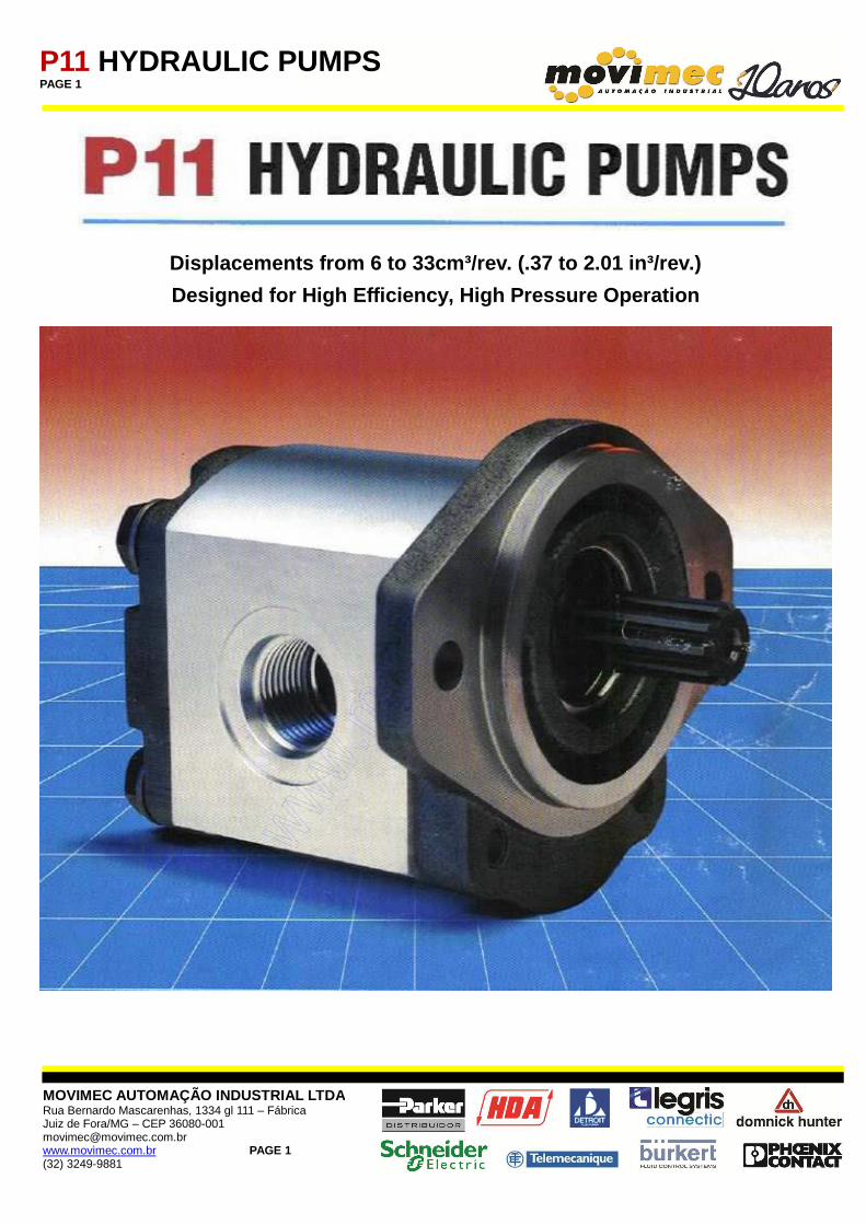
Displacements from 6 to 33cm³/rev. (.37 to 2.01 in³ /rev.)
Designed for High Efficiency, High Pressure Operati on

P11 HYDRAULIC PUMPS PAGE 2
MOVIMEC AUTOMAÇÃO INDUSTRIAL LTDA Rua Bernardo Mascarenhas, 1334 gl 111 – Fábrica Juiz de Fora/MG – CEP 36080-001 [email protected] www.movimec.com.br PAGE 2 (32) 3249-9881
P11 series gear pumps are an advanced-performance version of the international “bushing block” style pumps. P11 series offer superior performance, high efficiency and low noise operation at high operation pressures. A wide variety of standard options are available to meet specific application requirements, worldwide.
Design Features • Up to 4000psi/276 bar continuous operation. High strength materials and large journal diameters provide low bearing loads for high pressure operation. • Low noise. 13-tooth gear profile and optimized flow metering provide reduced pressure pulsations and exceptionally quiet operation. • High efficiency. Pressure balanced bearing blocks assure maximum efficiency under all operating conditions. • Application flexibility. International mounts and connections, integrated valve capabilities and common inlet multiple pump configurations, provide unmatched design and application versatility.
P11 PUMP SPECIFICATIONS Pump Displacements cm³/rev.
in³/rev. 6
.37 8
.49 10 .61
11 .67
14 .85
16 .98
19 1.16
23 1.4
27 1.65
31 1.89
33 2.01
Continuous Pressure bar psi
276 4000
276 4000
276 4000
276 4000
276 4000
276 4000
276 4000
234 3400
200 2900
196 2850
185 2700
Intermittent Pressure bar psi
300 4400
300 4400
300 4400
300 4400
300 4400
300 4400
300 4400
255 3700
221 3200
217 3150
210 3000
Minimum Speed @ Max. Outlet Pressure
rpm 500 500 500 500 500 500 500 500 500 500 500
Maximum Speed @ 0 Inlet & Max. Outlet Press.
rpm 4000 3600 3600 3600 3300 3000 3000 2800 2400 2300 2200
Pump Input Power @ Max. Pressure & 1800 rpm
kw hp
5.6 7.5
7.4 9.9
9.2 12.3
10.1 13.5
12.8 17.2
14.8 19.8
17.4 23.4
17.9 24.0
18.1 24.2
20.3 27.2
20.4 27.4
P11 HYDRAULIC PUMPS PAGE 3
MOVIMEC AUTOMAÇÃO INDUSTRIAL LTDA Rua Bernardo Mascarenhas, 1334 gl 111 – Fábrica Juiz de Fora/MG – CEP 36080-001 [email protected] www.movimec.com.br PAGE 3 (32) 3249-9881
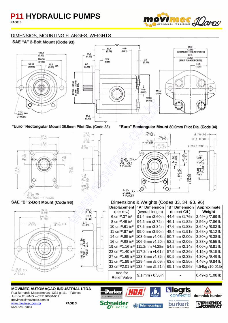
DIMENSIOS, MOUNTING FLANGES, WEIGHTS _ _ _ _ _ _
Dimensions & Weights (Codes 33, 34, 93, 96)
Displacement (per rev.)
“A” Dimension (overall length)
“B” Dimension (to port C/L)
Approximate Weight
6 cm³/.37 in³ 91.4mm /3.60in 44.6mm /1.76in 3.49kg /7.69 lb 8 cm³/.49 in³ 94.5mm /3.72in 46.1mm /1.82in 3.56kg /7.86 lb 10 cm³/.61 in³ 97.5mm /3.84in 47.6mm /1.88in 3.64kg /8.02 lb 11 cm³/.67 in³ 99.0mm /3.90in 48.4mm /1.91in 3.68kg /8.12 lb 14 cm³/.85 in³ 103.6mm /4.08in 50.7mm /2.00in 3.80kg /8.38 lb 16 cm³/.98 in³ 106.6mm /4.20in 52.2mm /2.06in 3.88kg /8.55 lb 19 cm³/1.16 in³ 111.2mm /4.38in 54.5mm /2.14in 4.00kg /8.81 lb 23 cm³/1.40 in³ 117.2mm /4.61in 57.5mm /2.26in 4.15kg /9.15 lb 27 cm³/1.65 in³ 123.3mm /4.85in 60.5mm /2.38in 4.30kg /9.49 lb 31 cm³/1.89 in³ 129.4mm /5.09in 63.6mm /2.50in 4.46kg /9.84 lb 33 cm³/2.01 in³ 132.4mm /5.21in 65.1mm /2.56in 4.54kg /10.01lb
Add for Relief Valve
9.1 mm / 0.36in - 0.49kg /1.08 lb
P11 HYDRAULIC PUMPS PAGE 4
MOVIMEC AUTOMAÇÃO INDUSTRIAL LTDA Rua Bernardo Mascarenhas, 1334 gl 111 – Fábrica Juiz de Fora/MG – CEP 36080-001 [email protected] www.movimec.com.br PAGE 4 (32) 3249-9881
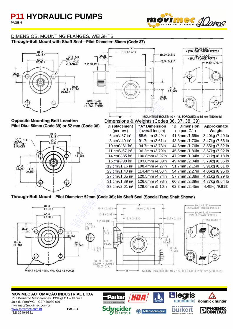
DIMENSIOS, MOUNTING FLANGES, WEIGHTS _ _ _ _ _ _
Dimensions & Weights (Codes 36, 37, 38, 39)
Displacement (per rev.)
“A” Dimension (overall length)
“B” Dimension (to port C/L)
Approximate Weight
6 cm³/.37 in³ 88.6mm /3.49in 41.8mm /1.65in 3.40kg /7.49 lb 8 cm³/.49 in³ 91.7mm /3.61in 43.3mm /1.70in 3.47kg /7.66 lb 10 cm³/.61 in³ 94.7mm /3.73in 44.8mm /1.76in 3.55kg /7.82 lb 11 cm³/.67 in³ 96.2mm /3.79in 45.6mm /1.80in 3.57kg /7.92 lb 14 cm³/.85 in³ 100.8mm /3.97in 47.9mm /1.94in 3.71kg /8.18 lb 16 cm³/.98 in³ 103.8mm /4.09in 49.4mm /2.04in 3.79kg /8.35 lb
19 cm³/1.16 in³ 108.4mm /4.27in 51.7mm /2.15in 3.91kg /8.61 lb 23 cm³/1.40 in³ 114.4mm /4.50in 54.7mm /2.27in 4.06kg /8.95 lb 27 cm³/1.65 in³ 120.5mm /4.74in 57.7mm /2.38in 4.21kg /9.29 lb 31 cm³/1.89 in³ 126.6mm /4.98in 60.8mm /2.39in 4.37kg /9.64 lb 33 cm³/2.01 in³ 129.6mm /5.10in 62.3mm /2.45in 4.45kg /9.81lb
P11 HYDRAULIC PUMPS PAGE 5
MOVIMEC AUTOMAÇÃO INDUSTRIAL LTDA Rua Bernardo Mascarenhas, 1334 gl 111 – Fábrica Juiz de Fora/MG – CEP 36080-001 [email protected] www.movimec.com.br PAGE 5 (32) 3249-9881
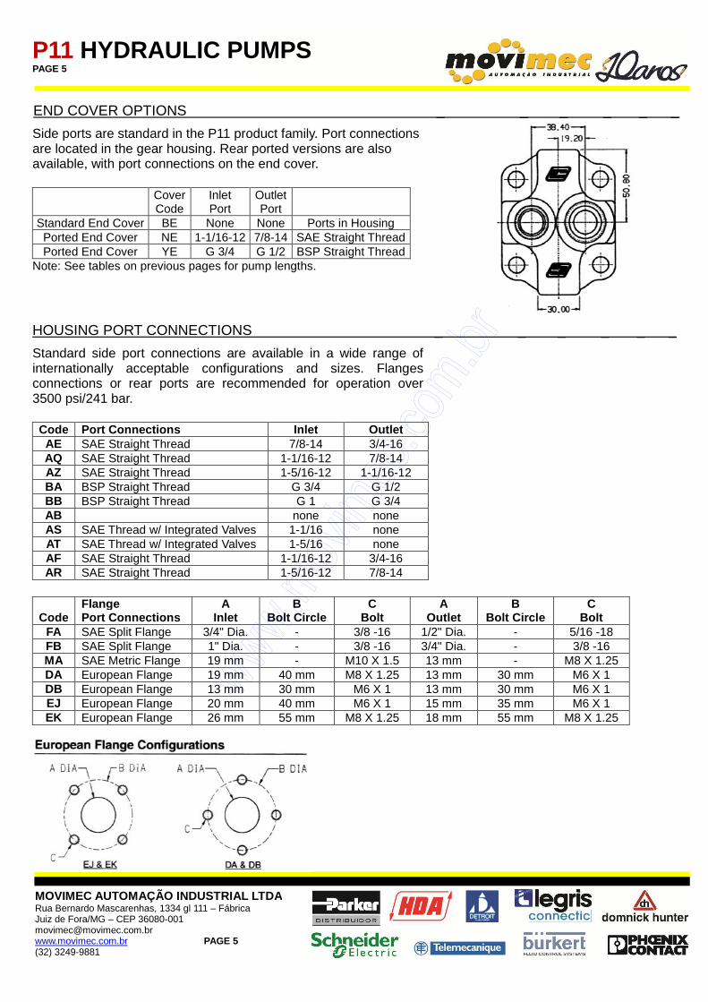
END COVER OPTIONS _ _ _ _ _ _
Side ports are standard in the P11 product family. Port connections are located in the gear housing. Rear ported versions are also available, with port connections on the end cover.
Cover Code
Inlet Port
Outlet Port
Standard End Cover BE None None Ports in Housing Ported End Cover NE 1-1/16-12 7/8-14 SAE Straight Thread Ported End Cover YE G 3/4 G 1/2 BSP Straight Thread
Note: See tables on previous pages for pump lengths. HOUSING PORT CONNECTIONS _ _ _ _ _ _
Standard side port connections are available in a wide range of internationally acceptable configurations and sizes. Flanges connections or rear ports are recommended for operation over 3500 psi/241 bar. Code Port Connections Inlet Outlet AE SAE Straight Thread 7/8-14 3/4-16 AQ SAE Straight Thread 1-1/16-12 7/8-14 AZ SAE Straight Thread 1-5/16-12 1-1/16-12 BA BSP Straight Thread G 3/4 G 1/2 BB BSP Straight Thread G 1 G 3/4 AB none none AS SAE Thread w/ Integrated Valves 1-1/16 none AT SAE Thread w/ Integrated Valves 1-5/16 none AF SAE Straight Thread 1-1/16-12 3/4-16 AR SAE Straight Thread 1-5/16-12 7/8-14
Code Flange Port Connections
A Inlet
B Bolt Circle
C Bolt
A Outlet
B Bolt Circle
C Bolt
FA SAE Split Flange 3/4" Dia. - 3/8 -16 1/2" Dia. - 5/16 -18 FB SAE Split Flange 1" Dia. - 3/8 -16 3/4" Dia. - 3/8 -16 MA SAE Metric Flange 19 mm - M10 X 1.5 13 mm - M8 X 1.25 DA European Flange 19 mm 40 mm M8 X 1.25 13 mm 30 mm M6 X 1 DB European Flange 13 mm 30 mm M6 X 1 13 mm 30 mm M6 X 1 EJ European Flange 20 mm 40 mm M6 X 1 15 mm 35 mm M6 X 1 EK European Flange 26 mm 55 mm M8 X 1.25 18 mm 55 mm M8 X 1.25
P11 HYDRAULIC PUMPS PAGE 6
MOVIMEC AUTOMAÇÃO INDUSTRIAL LTDA Rua Bernardo Mascarenhas, 1334 gl 111 – Fábrica Juiz de Fora/MG – CEP 36080-001 [email protected] www.movimec.com.br PAGE 6 (32) 3249-9881
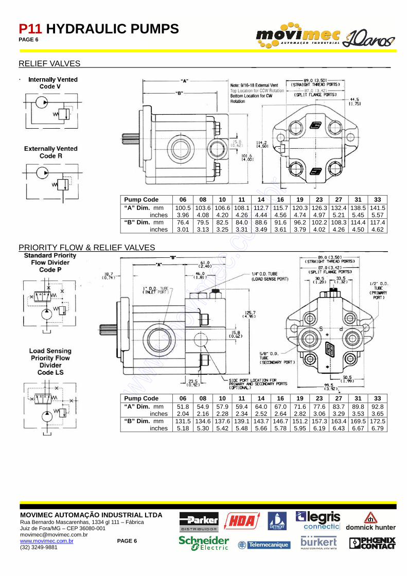
RELIEF VALVES _ _ _ _ _ _
.
Pump Code 06 08 10 11 14 16 19 23 27 31 33 “A” Dim. mm inches
100.5 3.96
103.6 4.08
106.6 4.20
108.1 4.26
112.7 4.44
115.7 4.56
120.3 4.74
126.3 4.97
132.4 5.21
138.5 5.45
141.5 5.57
“B” Dim. mm inches
76.4 3.01
79.5 3.13
82.5 3.25
84.0 3.31
88.6 3.49
91.6 3.61
96.2 3.79
102.2 4.02
108.3 4.26
114.4 4.50
117.4 4.62
PRIORITY FLOW & RELIEF VALVES _ _ _ _
Pump Code 06 08 10 11 14 16 19 23 27 31 33 “A” Dim. mm inches
51.8 2.04
54.9 2.16
57.9 2.28
59.4 2.34
64.0 2.52
67.0 2.64
71.6 2.82
77.6 3.06
83.7 3.29
89.8 3.53
92.8 3.65
“B” Dim. mm inches
131.5 5.18
134.6 5.30
137.6 5.42
139.1 5.48
143.7 5.66
146.7 5.78
151.2 5.95
157.3 6.19
163.4 6.43
169.5 6.67
172.5 6.79
P11 HYDRAULIC PUMPS PAGE 7
MOVIMEC AUTOMAÇÃO INDUSTRIAL LTDA Rua Bernardo Mascarenhas, 1334 gl 111 – Fábrica Juiz de Fora/MG – CEP 36080-001 [email protected] www.movimec.com.br PAGE 7 (32) 3249-9881
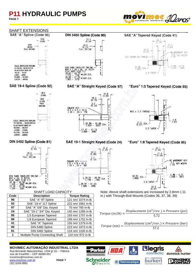
SHAFT EXTENSIONS _ _ _ _
SHAFT LOAD CAPACITY
Code Description Torque Rating 96 SAE “A” 9T Spline 121 nm/ 1074 in-lb 92 SAE “19-4” 11T Spline 222 nm/ 1961 in-lb 97 SAE “A” 5/8” Dia. Keyed 75 nm/ 765 in-lb 24 SAE “19-1” 3/4” Dia. Keyed 145 nm/ 1285 in-lb 85 1:5 European Tapered 193 nm/ 1707 in-lb 86 1:8 European Tapered 198 nm/ 1752 in-lb 41 SAE “A” Tapered 156 nm/ 1379 in-lb 80 DIN 5480 Spline 223 nm/ 1973 in-lb 81 DIN 5482 Spline 124 nm/ 1100 in-lb 1 Multiple Pump Connecting Shaft 110 nm/ 972 in-lb
Note: Above shaft extensions are increased by 2.8mm (.11 in.) with Through-Bolt Mounts (Codes 36, 37, 38, 39)
������(/� ) =����������(�/���. ) × ��������(��)
5.72
������(�) =����������(��³/���. ) × ��������( ��)
57.2
P11 HYDRAULIC PUMPS PAGE 8
MOVIMEC AUTOMAÇÃO INDUSTRIAL LTDA Rua Bernardo Mascarenhas, 1334 gl 111 – Fábrica Juiz de Fora/MG – CEP 36080-001 [email protected] www.movimec.com.br PAGE 8 (32) 3249-9881
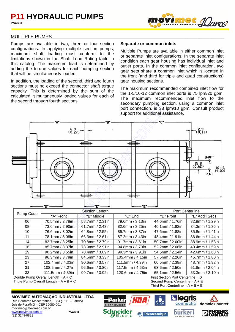
MULTIPLE PUMPS_ _ _ _ _
Pumps are available in two, three or four section configurations. In applying multiple section pumps, maximum shaft loading must conform to the limitations shown in the Shaft Load Rating table in this catalog. The maximum load is determined by adding the torque values for each pumping section that will be simultaneously loaded.
In addition, the loading of the second, third and fourth sections must no exceed the connector shaft torque capacity. This is determined by the sum of the calculated, simultaneously loaded values for each of the second through fourth sections.
Separate or common inlets
Multiple Pumps are available in either common inlet or separate inlet configurations. In the separate inlet condition each gear housing has individual inlet and outlet ports. In the common inlet configuration, two gear sets share a common inlet which is located in the front (and third for triple and quad constructions) gear housing sections.
The maximum recommended combined inlet flow for the 1-5/16-12 common inlet ports is 75 lpm/20 gpm. The maximum recommended inlet flow to the secondary pumping section, using a common inlet port connection, is 38 lpm/10 gpm. Consult product support for additional assistance.
Pump Code
Section Length Port Centerline “A” Front “B” Middle “C” End “D” Front “E” Add’l Secs.
06 70.5mm / 2.78in 58.7mm / 2.31in 79.6mm / 3.13in 44.6mm / 1.76in 32.8mm / 1.29in 08 73.6mm / 2.90in 61.7mm / 2.43in 82.6mm / 3.25in 46.1mm / 1.82in 34.3mm / 1.35in 10 76.6mm / 3.02in 64.8mm / 2.55in 85.7mm / 3.37in 47.6mm / 1.88in 35.8mm / 1.41in 11 78.1mm / 3.08in 66.3mm / 2.61in 87.2mm / 3.43in 48.4mm / 1.91in 36.6mm / 1.44in 14 82.7mm / 3.25in 70.8mm / 2.79in 91.7mm / 3.61in 50.7mm / 2.00in 38.9mm / 1.53in 16 85.7mm / 3.37in 73.9mm / 2.91in 94.8mm / 3.73in 52.2mm / 2.06in 40.4mm / 1.59in 19 90.2mm / 3.55in 78.4mm / 3.09in 99.3mm / 3.91in 54.5mm / 2.14in 42.6mm / 1.68in 23 96.3mm / 3.79in 84.5mm / 3.33in 105.4mm / 4.15in 57.5mm / 2.26in 45.7mm / 1.80in 27 102.4mm / 4.03in 90.6mm / 3.57in 111.5mm / 4.39in 60.5mm / 2.38in 48.7mm / 1.92in 31 108.5mm / 4.27in 96.6mm / 3.80in 117.5mm / 4.63in 63.6mm / 2.50in 51.8mm / 2.04in 33 111.5mm / 4.39in 99.7mm / 3.92in 120.6mm / 4.75in 65.1mm / 2.56in 53.3mm / 2.10in
Double Pump Overall Length = A + C First Section Port Centerline = D Triple Pump Overall Length = A + B + C Second Pump Centerline = A + E
Third Port Centerline = A + B + E
P11 HYDRAULIC PUMPS PAGE 9
MOVIMEC AUTOMAÇÃO INDUSTRIAL LTDA Rua Bernardo Mascarenhas, 1334 gl 111 – Fábrica Juiz de Fora/MG – CEP 36080-001 [email protected] www.movimec.com.br PAGE 9 (32) 3249-9881
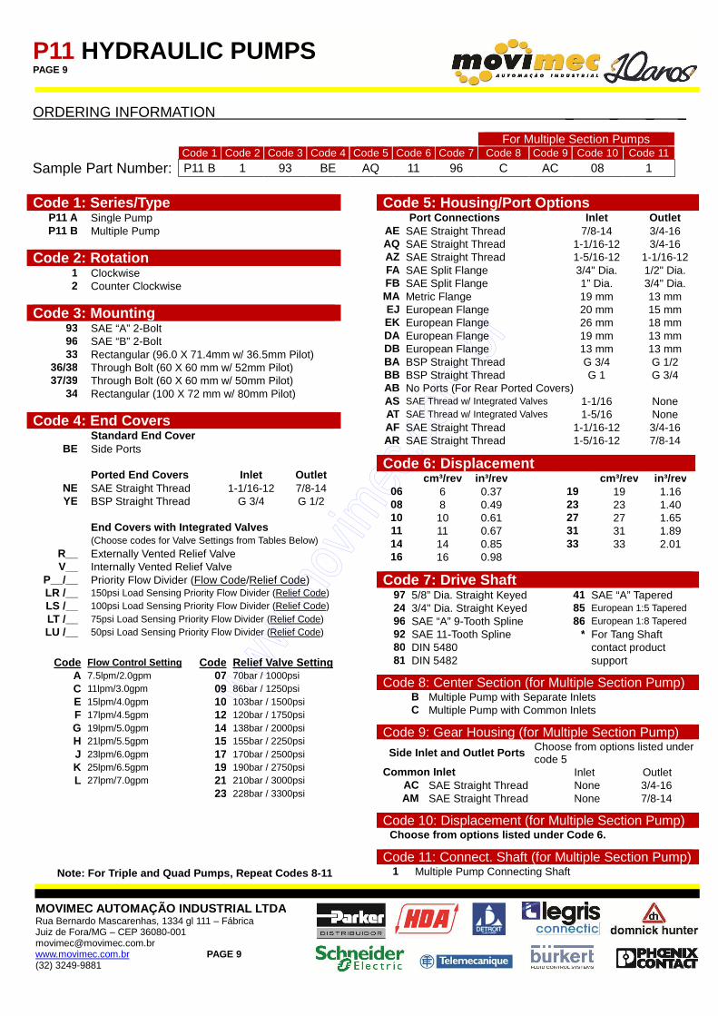
ORDERING INFORMATION _ _ _ _
For Multiple Section Pumps Code 1 Code 2 Code 3 Code 4 Code 5 Code 6 Code 7 Code 8 Code 9 Code 10 Code 11
Sample Part Number: P11 B 1 93 BE AQ 11 96 C AC 08 1
Code 1: Series/Type
P11 A Single Pump P11 B Multiple Pump
Code 2: Rotation 1 Clockwise 2 Counter Clockwise
Code 3: Mounting 93 SAE “A” 2-Bolt 96 SAE “B” 2-Bolt 33 Rectangular (96.0 X 71.4mm w/ 36.5mm Pilot)
36/38 Through Bolt (60 X 60 mm w/ 52mm Pilot) 37/39 Through Bolt (60 X 60 mm w/ 50mm Pilot)
34 Rectangular (100 X 72 mm w/ 80mm Pilot)
Code 4: End Covers Standard End Cover
BE Side Ports Ported End Covers Inlet Outlet
NE SAE Straight Thread 1-1/16-12 7/8-14 YE BSP Straight Thread G 3/4 G 1/2
End Cover s with Integrated Valves (Choose codes for Valve Settings from Tables Below)
R__ Externally Vented Relief Valve V__ Internally Vented Relief Valve
P__/__ Priority Flow Divider (Flow Code/Relief Code) LR /__ 150psi Load Sensing Priority Flow Divider (Relief Code) LS /__ 100psi Load Sensing Priority Flow Divider (Relief Code) LT /__ 75psi Load Sensing Priority Flow Divider (Relief Code) LU /__ 50psi Load Sensing Priority Flow Divider (Relief Code)
Code Flow Control Setting Code Relief Valve Setting
A 7.5lpm/2.0gpm 07 70bar / 1000psi C 11lpm/3.0gpm 09 86bar / 1250psi E 15lpm/4.0gpm 10 103bar / 1500psi F 17lpm/4.5gpm 12 120bar / 1750psi G 19lpm/5.0gpm 14 138bar / 2000psi H 21lpm/5.5gpm 15 155bar / 2250psi J 23lpm/6.0gpm 17 170bar / 2500psi K 25lpm/6.5gpm 19 190bar / 2750psi L 27lpm/7.0gpm 21 210bar / 3000psi
23 228bar / 3300psi
Note: For Triple and Quad Pumps, Repeat Codes 8-11
Code 5: Housing /Port Options Port Connections Inlet Outlet
AE SAE Straight Thread 7/8-14 3/4-16 AQ SAE Straight Thread 1-1/16-12 3/4-16 AZ SAE Straight Thread 1-5/16-12 1-1/16-12 FA SAE Split Flange 3/4" Dia. 1/2" Dia. FB SAE Split Flange 1” Dia. 3/4" Dia. MA Metric Flange 19 mm 13 mm EJ European Flange 20 mm 15 mm EK European Flange 26 mm 18 mm DA European Flange 19 mm 13 mm DB European Flange 13 mm 13 mm BA BSP Straight Thread G 3/4 G 1/2 BB BSP Straight Thread G 1 G 3/4 AB No Ports (For Rear Ported Covers) AS SAE Thread w/ Integrated Valves 1-1/16 None AT SAE Thread w/ Integrated Valves 1-5/16 None AF SAE Straight Thread 1-1/16-12 3/4-16 AR SAE Straight Thread 1-5/16-12 7/8-14
Code 6: Displacement cm³/rev in³/rev cm³/rev in³/rev
06 6 0.37 19 19 1.16 08 8 0.49 23 23 1.40 10 10 0.61 27 27 1.65 11 11 0.67 31 31 1.89 14 14 0.85 33 33 2.01 16 16 0.98
Code 7: Drive Shaft 97 5/8” Dia. Straight Keyed 41 SAE “A” Tapered 24 3/4" Dia. Straight Keyed 85 European 1:5 Tapered 96 SAE “A” 9-Tooth Spline 86 European 1:8 Tapered 92 SAE 11-Tooth Spline * For Tang Shaft 80 DIN 5480 contact product 81 DIN 5482 support
Code 8: Center Section (for Multiple Section Pump) B Multiple Pump with Separate Inlets C Multiple Pump with Common Inlets
Code 9: Gear Housing (for Multiple Section Pump)
Side Inlet and Outlet Ports Choose from options listed under code 5
Common Inlet Inlet Outlet AC SAE Straight Thread None 3/4-16 AM SAE Straight Thread None 7/8-14
Code 10: Displacement (for Multiple Section Pump) Choose from options listed under Code 6.
Code 11: Connect. Shaft (for Multiple Section Pump) 1 Multiple Pump Connecting Shaft