oyster creek generating station - technical specification ... · general electric stability...
TRANSCRIPT

AmerGen, AmerGen Energy Company, LLC www exeloncorp com An Exelon/British Energy Company 200 Exelon Way
Suite 345
Kennett Square, PA 19348
10 CFR 50.90
April 26, 2002 2130-02-20080
U.S. Nuclear Regulatory Commission ATTN: Document Control Desk Washington, DC 20555-0001
Subject: Technical Specification Change Request No. 308 General Electric Stability Analysis Methodology
Oyster Creek Generating Station Facility Operating License No. DPR- 16 NRC Docket No. 50-219
In accordance with 10 CFR 50.4(b)(1), enclosed is Technical Specification Change Request No. 308.
The purpose of this Technical Specification Change Request is to revise Oyster Creek Technical Specifications to incorporate the BWR Owner's Group (BWROG) defined stability Option II solution methodology to assure that coupled neutronic/thermal-hydraulic instabilities are adequately detected and suppressed. The Option II solution is documented in NEDO-32465-A, "Reactor Stability Detect and Suppress Solutions Licensing Basis Methodology for Reload Applications," August 1996, which has been previously reviewed and approved by the NRC. The Option II solution demonstrates that existing quadrant-based Average Power Range Monitor (APRM) trip systems will initiate a reactor scram for a postulated reactor instability and avoid violating the Minimum Critical Power Ratio (MCPR) safety limit. The Oyster Creek plantspecific analysis using the Option II solution is provided in Enclosure 3, NEDC-33065P, Revision 0, "Application of Stability Long-Term Solution Option II To Oyster Creek," April 2002. Enclosure 3 provides proprietary information as defined in 10 CFR 2.790(a)(4). Accordingly, it is requested that Enclosure 3 be withheld from public disclosure. An affidavit certifying the basis for this application for withholding as required by 10 CFR 2.790(b)(1) is also enclosed with this letter. Enclosure 4 provides a non-proprietary version of NEDC-33065P, Rev. 0.

2130-02-20080 April 26, 2002 Page 2
In addition, changes are proposed which will increase the APRM flow biased neutron flux scram and control rod block settings to allow plant operation in the previously approved Extended Load Line Limit Analysis (ELLLA) region. Oyster Creek is currently restricted from full use of the ELLLA region of the power/flow map because of the flow biased rod block setpoints. This revision will modify the APRM Neutron Flux, Scram and Neutron Flux, Control Rod Block Limiting Safety System Settings contained in Technical Specifications 2.3.A. I and 2.3.B, respectively. The revised Limiting Safety System Settings will improve plant operations by allowing full utilization of the previously licensed Oyster Creek core power-flow operating domain, without compromising plant safety. Operation in the ELLLA region was approved by Oyster Creek Amendment No. 111, dated October 27, 1986.
Using the standards in 10 CFR 50.92, AmerGen Energy Company, LLC (AmerGen) has concluded that these proposed changes do not constitute a significant hazards consideration, as described in the enclosed analysis performed in accordance with 10 CFR 50.91 (a)(1). Pursuant to 10 CFR 50.91 (b)(1), a copy of this Technical Specification Change Request is provided to the designated official of the State of New Jersey, Bureau of Nuclear Engineering, as well as the Chief Executive of the township in which the facility is located.
This proposed change to the Technical Specifications has undergone a safety review in accordance with Section 6.5 of the Oyster Creek Technical Specifications. No new regulatory commitments are established by this submittal.
NRC approval of this change is requested by September 30, 2002. This requested approval date is to allow sufficient time to update the affected plant procedures and provide appropriate training prior to Cycle 19 startup. Implementation of this change for Cycle 19 initial startup after the 19R refueling outage will: (1) incorporate a more conservative stability analysis solution appropriate for the use of GE 1 fuel in Cycle 19, and (2) improve operational flexibility, reducing the number and/or magnitude of reactor maneuvers and thereby improving capacity factor and reducing fuel, human and equipment challenges. Additionally, the availability of lower core flow rates will enhance spectral shift operation and thus reduce fuel costs. Once approved, the amendment shall be implemented within 30 days.
If any additional information is needed, please contact David J. Distel at (610) 765-5517.

2130-02-20080 April 26, 2002 Page 3
I declare under penalty of perjury that the foregoing is true and correct.
Sincerely,
Michael P. Gallagher Director, Licensing & Regulatory Affairs Mid-Atlantic Regional Operating Group
Enclosures: (1) Oyster Creek Technical Specification Change Request No. 308 Evaluation of Proposed Changes
(2) Oyster Creek Technical Specification Change Request No. 308 Markup of Proposed Technical Specification Page Changes
(3) NEDC-33065P, Rev. 0, "Application of Stability Long-Term Solution Option II To Oyster Creek," April 2002, Proprietary Version
(4) NEDC-33065, Rev. 0, "Application of Stability Long-Term Solution Option II To Oyster Creek," April 2002, Non-Proprietary Version
(5) General Electric Company Affidavit Certifying Request For Withholding From Public Disclosure
cc: H. J. Miller, Administrator, USNRC Region I P. S. Tam, USNRC Senior Project Manager, Oyster Creek L. A. Dudes, USNRC Senior Resident Inspector, Oyster Creek File No. 02033
zi -_ Z6-0 2. Executed On

United States of America Nuclear Regulatory Commission
In the Matter of ) Docket No. 50-219
AmerGen Energy Company, LLC )
Certificate of Service
This is to certify that a copy of Technical Specification Change Request No. 308 for the Oyster Creek Generating Station Operating License, filed with the U.S. Nuclear Regulatory Commission on April 26, 2002, has this 26th day of April 2002 been served on the State of New Jersey Bureau of Nuclear Engineering, as well as the Chief Executive of the township in which the facility is located, by deposit in the United States mail, addressed as follows:
The Honorable Louis Amato Mayor of Lacey Township
818 West Lacey Road Forked River, NJ 08731
Mr. Kent Tosch, Director Bureau of Nuclear Engineering
Department of Environmental Protection CN 415
Trenton, NJ 08628
By: _ _ _ _ _ _ _ " Michael P. Gallagher Director, Licensing & Regulatory Affairs

ENCLOSURE 1
Oyster Creek Technical Specification Change Request No. 308
Evaluation of Proposed Changes

Enclosure 1 2130-02-20080 Page 1
1.0 INTRODUCTION
This letter is a request to amend Operating License No. DPR-16.
The proposed changes would revise the Operating License to: (1) incorporate the BWR Owner's Group (BWROG) defined stability Option II solution methodology to assure that coupled neutronic/thermal-hydraulic instabilities are adequately detected and suppressed, and (2) increase the APRM flow biased neutron flux scram and control rod block settings to allow plant operation in the previously approved Extended Load Line Limit Analysis (ELLLA) region. This change supports Cycle 19 operation. NRC approval of this change is requested by September 30, 2002 in order to allow sufficient time to update the affected plant procedures and provide appropriate training prior to Cycle 19 startup.
AmerGen Energy Company, LLC (AmerGen) requests that the following changed replacement pages be inserted into the existing Technical Specifications:
Revised Technical Specification Pages: 2.3-1, 2.3-2, 2.3-4, 2.3-5, 2.3-6, 3.1-1, 3.1-7, 3.10-2, 3.10-3, and 3.10-4.
The marked up pages showing the requested changes are provided in Enclosure 2.
2.0 DESCRIPTION OF PROPOSED AMENDMENT
The Oyster Creek Cycle 19 core design will utilize GEl 1 fuel which has a 9x9 fuel rod array. General Electric Corporation (GE) has recommended that Oyster Creek transition to the Generic BWROG Long Term Stability Solution Option II for operating Cycle 19. The Generic BWROG Long Term Stability Solution Option II is the same methodology approved by the NRC for Nine Mile Point Unit 1 (Facility Operating License No. DPR63) in Amendment No. 168, dated September 21, 1999.
The BWR Owners' Group (BWROG) defined several stability long-term solutions which meet the requirements of 10 CFR 50, Appendix A, General Design Criteria (GDC) 10 and 12. The Option II solution proposed for use at Oyster Creek demonstrates that existing quadrant-based Average Power Range Monitor (APRM) trip systems will initiate a reactor scram for a postulated reactor instability and avoid violating the Minimum Critical Power Ratio (MCPR) safety limit. The quadrant-based APRM system is unique to BWR/2 (e.g., Oyster Creek) designs in that Local Power Range Monitor (LPRM) instrument assignments to the APRMs are arranged in separate quadrants of the reactor. Thus, BWR/2s would have a substantial APRM response to a postulated reactor

Enclosure 1 2130-02-20080 Page 2
instability, which oscillates in either an in-phase (core wide) or out-of-phase (regional) oscillation mode. Plant-specific analysis for Oyster Creek Cycle 19 using the Option II solution (NEDC-33065P, Rev. 0) indicated that changes to the Technical Specification 2.3.A. 1 APRM flow biased neutron flux scram settings would be required. The changes are required to limit the oscillation magnitude at reactor trip, thereby limiting the associated Critical Power Ratio (CPR) change and, in conjunction with MCPR operating limits, assure compliance with the MCPR safety limit. Accordingly, AmerGen has proposed changes to the Oyster Creek Technical Specification APRM flow biased neutron flux scram setpoint to limit the oscillation magnitude consistent with NEDC33065P, Rev. 0. Also, changes to the Technical Specification 2.3.B APRM flow biased rod block settings are proposed to be consistent with the scram setpoint changes.
Oyster Creek also proposes to revise the APRM Neutron Flux, Scram and Neutron Flux, Control Rod Block Limiting Safety System Settings contained in Technical Specifications 2.3.A. I and 2.3.B, respectively, to allow full utilization of the currently analyzed and licensed Oyster Creek core power-flow operating domain. The existing APRM Neutron Flux, Scram and Neutron Flux, Control Rod Block Limiting Safety System Settings were instituted in the Oyster Creek Technical Specifications in Amendment No. 111, dated October 27, 1986. This amendment supported the Oyster Creek Operating Cycle 11 Reload, and implemented the Oyster Creek Extended Load Line Limit Analysis (ELLLA) (GE Report MDE-63-0386, "Extended Load Line Limit Analysis for Oyster Creek Nuclear Generating Station Cycle 10", March, 1986). The Extended Load Line Limit Analysis justified operation in an extended region above the 100% rod line, thereby expanding the licensed Oyster Creek power-flow operating domain. The extended region includes a "flow window" (85% core flow to 100% core flow) in which full power operation is allowed. However, the actual implementation of ELLLA, as established by the existing APRM Neutron Flux, Scram and Neutron Flux, Control Rod Block Limiting Safety System Settings, does not permit full utilization of the previously licensed power-flow operating domain since the effective "flow window" is limited to a minimum core flow of approximately 93% of rated flow at full reactor power.
The revised Limiting Safety System Settings will improve plant operations by allowing full utilization of the licensed Oyster Creek core power-flow operating domain. Full power operation, with core flow as low as the minimum licensed value (85% of rated), will be achievable. The resulting increased "flow window" will improve operational flexibility, reducing the number and/or magnitude of reactor maneuvers and thereby improving capacity factor and reducing fuel, human and equipment challenges.

Enclosure 1 2130-02-20080 Page 3
In addition, the ability to operate at reduced core flow rates can improve fuel utilization. The availability of lower core flow rates will enhance flow spectral shift operation, thereby reducing fuel costs and providing an additional economic benefit.
In summary, this change revises Oyster Creek Technical Specifications to incorporate the BWR Owner's Group defined stability Option II solution methodology to assure that coupled neutronic/thermal-hydraulic instabilities are adequately detected and suppressed. The Option II solution is documented in NEDO-32465-A, "Reactor Stability Detect and Suppress Solutions Licensing Basis Methodology for Reload Applications," August 1996, which has been previously reviewed and approved by the NRC. The Option II solution demonstrates that existing quadrant-based Average Power Range Monitor (APRM) trip systems will initiate a reactor scram for a postulated reactor instability and avoid violating the Minimum Critical Power Ratio (MCPR) safety limit. In addition, changes are proposed which will increase the APRM flow biased neutron flux scram and control rod block settings to allow plant operation in the previously approved Extended Load Line Limit Analysis (ELLLA) region. The revised Limiting Safety System Settings will improve plant operations by allowing full utilization of the previously licensed Oyster Creek core power-flow operating domain, without compromising plant safety.
Technical Specification 2.3 Bases contained on pages 2.3-4, 2.3-5 and 2.3-6 are revised to reflect the proposed changes to the limiting safety system settings described above. In addition, Technical Specification 2.3 Bases contained on pages 2.3-4 and 2.3-5 are being revised to correct typographical errors. These revisions of the Bases are purely administrative changes.
Technical Specifications 3.1.B.3 and 3.10.C, and associated Bases on pages 3.1-7, 3.10-3, and 3.10-4, are revised to reflect the proposed change from the current OC long term stability solution to the Generic BWROG Long Term Stability Solution Option II.
3.0 BACKGROUND
The Oyster Creek APRM System consists of eight (8) identical channels. Each channel is provided with eight (8) inputs from the LPRM System to enable it to compute an accurate quadrant average thermal neutron flux. The averaging and trip circuits of the APRMs receive the total recirculation flow signals and use them to cause the output trip level setpoints to vary in accordance with a specific relationship between quadrant average power and total recirculation flow. The trip signal outputs of the APRMs are utilized in the Reactor Protection System (scram) and the Reactor Manual Control System (control rod block). The current Oyster Creek long-term stability solution is based on BWROG

Enclosure 1 2130-02-20080 Page 4
stability analyses and methodologies reported in NEDO-31708 and relies on the existing flow referenced APRM Neutron Flux Scram setpoint to provide fuel protection. The analyses reported in NEDO-31708 are based on fuel designs with an 8x8 fuel rod array (e.g., GE8, GE9 fuel). General Electric Corporation (GE) has recommended that Oyster Creek transition to the Generic BWROG Long Term Stability Solution Option II for use of GEl 1 fuel in operating Cycle 19.
In addition to the changes supporting Oyster Creek's stability solution, changes are proposed which will increase the APRM flow biased neutron flux scram and control rod block settings to allow plant operation in the ELLLA region. The revision consists of an increase in the value of the setpoints at rated flow while retaining the slope of the flow referenced setpoints. This change will increase the Rod Block and Flux Scram setpoint values. Operation of Oyster Creek in the extended operating region is currently analyzed (GE Report MDE-63-0386, "Extended Load Line Limit Analysis for Oyster Creek Nuclear Generating Station," March 1986), and licensed in Oyster Creek Technical Specification Amendment No. 11, dated October 27, 1986. The existing flow referenced APRM Rod Block setpoint line also acts to administer the "maximum licensed power line" (upper boundary of the extended operating domain) identified in the ELLLA report. The proposed setpoint revisions do not change the "maximum licensed power line."
4.0 REGULATORY REQUIREMENTS & GUIDANCE
10 CFR 50, Appendix A, General Design Criteria (GDC) 10 requires that the reactor core and associated coolant, control, and protective systems be designed with appropriate margin to assure that specified acceptable fuel design limits are not exceeded during any condition of normal operation, including the effects of anticipated occurrences. 10 CFR 50, Appendix A, GDC 12, requires that the reactor core and associated coolant, control, and protection systems be designed to assure that power oscillations which can result in conditions exceeding specified acceptable fuel design limits are not possible or can be reliably and readily detected and suppressed.
Under certain conditions, Boiling Water Reactors (BWRs) may be susceptible to coupled neutronic/thermal-hydraulic instabilities. These instabilities are characterized by periodic power and flow oscillations and result in density waves (i.e., regions of highly voided coolant periodically sweeping through the core). If the flow and power oscillations become large enough, and the density wave contains a sufficiently high void fraction, then the fuel cladding integrity safety limit could be challenged. The current Oyster Creek long-term stability solution was approved by the NRC (OC Amendment 176, December 1994). This solution is based on BWROG stability analyses and methodologies reported in NEDO-31708 and relies on the existing flow referenced APRM Neutron Flux Scram setpoint to provide fuel protection. The analyses reported in NEDO-31708 are based on fuel designs with an 8x8 fuel rod array (e.g., GE8, GE9 fuel).

Enclosure 1 2130-02-20080 Page 5
Operation of Oyster Creek in the extended operating region is currently analyzed (GE Report MDE-63-0386, "Extended Load Line Limit Analysis for Oyster Creek Nuclear Generating Station," March 1986) and licensed in Oyster Creek Technical Specification Amendment No. 111, dated October 27, 1986. The existing flow referenced APRM Rod Block setpoint line also acts to administer the "maximum licensed power line" (upper boundary of the extended operating domain) identified in the ELLLA report. The proposed revision to the flow referenced APRM Rod Block setpoint line can no longer function to administer the "maximum licensed power line." However, the proposed setpoint revisions do not change the "maximum licensed power line." Operation within the upper boundary of the extended operating region as established in the previously licensed ELLL analysis will be controlled by administrative core monitoring requirements for Cycle 19 and future cycles to ensure that the "maximum licensed power line" is not exceeded. This method of administering the "maximum licensed power line" is consistent with that utilized by other BWRs operating with ELLLA or Maximum Extended Load Line Limit Analysis (MELLLA).
5.0 TECHNICAL ANALYSIS
Current Flow Biased APRM Scram and Rod Block Trip Technical Specification
Existing Oyster Creek Technical Specification 2.3, Limiting Safety System Settings, applies to trip settings on automatic protective devices related to variables on which fuel safety limits have been placed. Technical Specification 2.3.A. I and 2.3.B delineate the relationships that establish the flow biased APRM scram and rod block trip settings. The maximum values of the scram and rod block trip settings are currently 115.7% and 108%, respectively. Analyses demonstrate that none of the postulated accidents results in violating the established criteria with a 115.7% scram trip setting.
Reactor power level may be varied by moving control rods or by varying the recirculation flow rate. The APRM system provides a control rod block to prevent rod withdrawal beyond a given point at a constant recirculation flow rate. This rod block trip setting, which is automatically varied with recirculation flow rate, prevents an increase in the reactor power level to excessive values due to control rod withdrawal. The flow variable trip setting provides substantial margin from fuel damage, assuming steady-state operation at the trip setting, over the entire recirculation flow range. The margin to the safety limit increases as the flow decreases for the specified trip setting versus flow relationship; therefore, the worst case MCPR which could occur during steady-state

Enclosure 1 2130-02-20080 Page 6
operation is at 108% of rated thermal power because of the APRM rod block trip setting. The actual power distribution in the core is established by specified control rod sequences and is monitored continuously by the in-core LPRM System. As with the APRM scram trip setting, the APRM rod block trip setting is adjusted downward if the core maximum fraction of limiting power density exceeds the fraction of rated thermal power, thus, preserving the APRM rod block safety margin.
The current Oyster Creek long-term stability solution is based on BWROG stability analyses and methodologies reported in NEDO-31708 and relies on the existing flow referenced APRM Neutron Flux Scram setpoint to provide fuel protection. The current stability analysis assumes an APRM neutron flux scram setpoint of 78% at 30% core flow (the existing Technical Specification value at 30% core flow is 77.3%).
Changes to the APRM Flow Biased Neutron Flux Scram and Control Rod Block Settings for Stability Protection
The BWR Owners' Group (BWROG) defined several stability long-term solutions which meet the GDC's stated above. The Option II solution proposed for use at Oyster Creek demonstrates that existing quadrant-based Average Power Range Monitor (APRM) trip systems will initiate a reactor scram for a postulated reactor instability and avoid violating the Minimum Critical Power Ratio (MCPR) safety limit. However, at Oyster Creek, the Technical Specification flow biased APRM flux trip setting must be modified for Option II implementation. This change is required to limit the oscillation magnitude at reactor trip, thereby limiting the associated CPR change and, in conjunction with MCPR operating limits, ensures protection of the MCPR Safety Limit. Accordingly, AmerGen has proposed changes to the Oyster Creek Technical Specification APRM flow biased neutron flux scram setpoint to limit the oscillation magnitude consistent with NEDC-33065P. Also, changes to the APRM flow biased rod block settings are proposed to be consistent with the scram setting changes. To implement this Technical Specification setting change, the eight (8) analog APRM Flow Bias Trip Units will be replaced with digital APRM Flow Control Trip Reference (FCTR) cards. With the FCTR cards in place, a scram setpoint can be established that will meet GDC 12 criterion for fuel design limit protection.
NEDC-33065P, "Application of Stability Long-Term Solution Option II to Oyster Creek" (Enclosure 3) provides a demonstration of the application of Option II methodology at Oyster Creek for Cycle 19. As indicated in NEDC-33065P, detect and suppress calculations are performed for two points along the rated rod line consistent with the BWROG detect and suppress methodology (BWR Owners' Group Reactor Stability Detect and Suppress Solutions Licensing Basis Methodology for Reload Applications, NEDO-32465), which was issued in May 1995. The accepted version, NEDO-32465-A was issued in August 1996. The two conditions start at MCPR operating limits along the rated rod line for (1) a five recirculation pump trip to natural circulation (i.e., 22.0% rated core flow) and (2) steady-state operation at 45% core flow.

Enclosure 1 2130-02-20080 Page 7
The five recirculation pump trip conservatively represents flow runback transients, including operation with one or two isolated recirculation loops, and the 45% core flow case conservatively represents plant startup conditions. In addition, NEDC-33065P documented the calculation of a revised Restricted Region boundary to be implemented at Oyster Creek.
The detect and suppress methodology applied to Oyster Creek is a conservative simplification of the BWROG detect and suppress methodology (NEDO-32465-A, August 1996). The Oyster Creek application analysis used a combination of bounding and representative inputs to demonstrate with a deterministic calculation that the final MCPR value at oscillation suppression is greater than the MCPR safety limit. The inputs and assumptions used in the analysis to demonstrate MCPR safety limit protection resulted in restrictions on Oyster Creek APRM scram trip setpoints and MCPR operating limits for stability Option II implementation. As indicated in NEDC-33065P, the specific restrictions are:
"* APRM trip analytical limit at 22.0% flow < 54.6% power "* APRM trip analytical limit at 45.0% flow:< 68.4% power
The proposed change to the APRM flow biased neutron flux scram and rod block Technical Specification setpoints (Technical Specification 2.3.A. 1 and 2.3.B) implements the required settings. The proposed changes will revise the Technical Specification APRM flow biased trip setpoint to be consistent with NEDC-33065P. The margin between the APRM flow biased neutron flux scram and the APRM flow biased control rod block in this region of the power/flow map (7.3%) is based on an evaluation and recommendation by GE. MCPR operating limits will be reviewed each reload which will assure the setpoint derived in NEDC-33065P will prevent the MCPR safety limit from being exceeded. The MCPR operating limits will be maintained in the Core Operating Limits Report.
The current Oyster Creek long-term stability solution was approved as Amendment 176 to the Oyster Creek Technical Specifications, dated December 29, 1994. Under Amendment 176, Technical Specification 3.1 .B.3 was added to Technical Specification 3.1, Protective Instrumentation. Technical Specification 3.1 .B.3 added requirements for LPRM operability associated with the Oyster Creek stability solution. The BWR Owner's Group (BWROG) defined stability Option II solution methodology addresses LPRM operability in a different manner and does not require these operability constraints. Thus, under the proposed change, Technical Specification 3.1 .B.3 is deleted consistent with NEDC-33065P. In addition, Technical Specification 3.1 Bases contained on page 3.1-7 are changed to reflect the proposed change above.
Amendment 176 to the Oyster Creek Technical Specifications also introduced changes to Technical Specification 3.10, Core Limits. Specifically, a minimum MCPR limit for

Enclosure 1 2130-02-20080 Page 8
each cycle was specified consistent with the Oyster Creek stability solution. The BWR Owner's Group (BWROG) defined stability Option II solution methodology addresses cycle specific MCPR limits in a different manner. As previously stated above, MCPR operating limits will be reviewed each reload which will assure the setpoint derived in NEDC-33065P will prevent the MCPR safety limits from being exceeded. The MCPR operating limits will be maintained in the Core Operating Limits Report. Thus, under the proposed change, Technical Specification 3.1 0.C is revised consistent with NEDC33065P. In addition, Technical Specification 3.10 Bases contained on page 3.10-3 are changed to reflect the proposed change above.
The BWR Owner's Group (BWROG) defined stability Option II solution methodology relies, in part, on the Oyster Creek MCPR flow multiplier, kf, to limit MCPR when operating at low flow conditions. Thus, under the proposed change, Technical Specification 3.10 Bases contained on page 3.10-4 are changed to reflect the association of the Oyster Creek MCPR flow multiplier, kf, with the stability solution consistent with NEDC-33065P.
New digital FCTR cards are being installed under 10 CFR 50.59 prior to Cycle 19 startup and will support implementation of Stability Solution Option II. The new digital FCTR cards are being designed to meet appropriate environmental qualification parameters which envelope plant-specific environmental conditions (temperature, humidity, pressure, seismic, and electromagnetic compatibility).
A bum-in process prior to installation and a "shakedown" period for the new digital FCTR cards is planned at the end of Cycle 18 operation to identify any plant-specific revisions that may be required to prevent spurious trips and alarms.
Technical Specification Section 6.9.1.f, Core Operating Limits Report, Subsection 2, lists those documents which describe the analytical methods used to determine the core operating limits and which have been previously reviewed and approved by the NRC. NEDO-32465-A, "Reactor Stability Detect and Suppress Solutions Licensing Basis Methodology for Reload Applications," August 1996, has been previously reviewed and approved by the NRC and is incorporated into NEDE-2401 1-P-A, General Electric Standard Application for Reactor Fuel (GESTAR-II). GESTAR-II is an existing reference in Oyster Creek Technical Specification Section 6.9.1 .f.
In summary, the revised Technical Specification settings implemented by the FCTR cards will provide more restrictive flow biased scram and rod block trip settings in the lower flow regions of the power/flow operating map and limit the magnitude of oscillations at reactor trip.

Enclosure 1 2130-02-20080 Page 9
Changes to Increase APRM Flow Biased Neutron Flux Scram and Control Rod Block Settings for Transient Protection
As previously discussed, Technical Specification 2.3, Limiting Safety System Settings, applies to trip settings on automatic protective devices related to variables on which fuel safety limits have been placed. This includes the APRM flow biased scram and rod block trip settings. In addition to the changes to the settings to support Oyster Creek's stability solution, changes are proposed which will increase the APRM flow biased neutron flux scram and control rod block settings to allow plant operation in the ELLLA region. The revision consists of a increase in the value of the setpoints at rated flow while retaining the slope of the flow referenced setpoints. This change will increase the Rod Block and Flux Scram setpoint values. The setpoints will be revised as follows:
Rod Block Scram
Current Setpoint: 0.90E-6*W(lb/hr) + 53.1 0.90E-6*W(lb/hr) + 60.8
Revised Setpoint: 0.90E-6*W(lb/hr) + 60.1 0.90E-6*W(lb/hr) + 65.1
The proposed revisions will increase the APRM Neutron Flux Scram and Rod Block setpoints and allow full reactor power operation at core flow as low as 85% of rated. Previously applied conservatisms in the actual setpoints to account for instrument drift, uncertainties, and typical APRM process noise are maintained. Operation of Oyster Creek in the extended operating region is currently analyzed (GE Report MDE-63-0386, "Extended Load Line Limit Analysis for Oyster Creek Nuclear Generating Station," March 1986), and licensed in Oyster Creek Technical Specification Amendment No. 111, dated October 27, 1986. The existing flow referenced APRM Rod Block setpoint line also acts to administer the "maximum licensed power line" (upper boundary of the extended operating domain) identified in the ELLLA report. The proposed revision to the flow referenced APRM Rod Block setpoint line can no longer function to administer the "maximum licensed power line." However, the proposed setpoint revisions do not change the "maximum licensed power line." Operation within the upper boundary of the extended operating region as established in the previously licensed ELLL analysis will be controlled by administrative core monitoring requirements for Cycle 19 and future cycles to ensure that the "maximum licensed power line" is not exceeded. This method of administering the "maximum licensed power line" is consistent with that utilized by other BWRs operating with ELLLA or Maximum Extended Load Line Limit Analysis (MELLLA).

Enclosure 1 2130-02-20080 Page 10
Attachment 1 provides a schematic showing the Extended Load Line Limit Analysis (ELLLA) region of the power/flow map as well as the current APRM flow biased neutron flux scram and rod block settings and stability restriction region. The current maximum values of the APRM flow biased neutron flux scram and rod block settings are 115.7% and 108%, respectively.
Analysis performed supports a 4.3% increase in the APRM flow biased scram analytical limit. Accordingly, a new maximum scram limit of 120% is proposed. The margin between the APRM flow biased neutron flux scram and the APRM flow biased control rod block in this region of the power/flow map (5%) is based on an evaluation and recommendation by GE (i.e., 120%-5%=1 15% control rod block limit). Analysis demonstrated that the 115% control rod block limit is acceptable. The proposed control rod block setting of 115% represents a 7% increase from the current value of 108%.
In the low flow region of the power/flow map, more conservative Technical Specification APRM flow biased scram and control rod block setpoints were proposed. The scram value calculated will limit the oscillation magnitude assuring that the plant MCPR safety limit value is not exceeded.
Attachment 2 provides a schematic showing the proposed APRM flow biased neutron flux scram and rod block settings and stability restriction region. The proposed maximum values of the APRM flow biased neutron flux scram and rod block settings are 120.0% and 115%, respectively (i.e., a 5% margin between the scram and rod block settings).
A review of the Oyster Creek Updated Final Safety Analysis Report (UFSAR) was performed to identify any design and licensing basis transient and/or accident events that may be impacted by the increased setpoints.
With the exception of the Control Rod Drop Accident (CRDA) described in UFSAR 15.4.9, the identified design basis accidents do not rely on, nor credit, the function of the APRM Neutron Flux Scram or Rod Block functions to mitigate consequences. The CRDA event results are based on generic evaluations which assume a nominal 120% APRM Neutron Flux Scram setpoint which is consistent with the proposed change. Thus, these events are not impacted by the revised Technical Specification flow referenced APRM Neutron Flux Rod Block and Scram setpoints.
The UFSAR review identified the following transient events that are impacted by the proposed change:
1. Rod Withdrawal Event (UFSAR 15.4.2) 2. Loss of Feedwater Heating (UFSAR 15.1.1) 3. MSIV Closure (UFSAR 15.2.4) 4. Startup of an Inactive Loop at an Incorrect Temperature (UFSAR 15.4.4)

Enclosure 1 2130-02-20080 Page 11
Evaluations were performed to determine the potential impact of the proposed change on the identified transient events. These evaluations are based on the existing operating Cycle 18 reload analyses, generic (non-cycle specific) safety analyses, and/or UFSAR event descriptions, as applicable.
I1. Rod Withdrawal Event (RWE)
The RWE (UFSAR 15.4.2) is limiting at full power conditions. The existing RWE analysis basis assumes an APRM Rod Block setpoint of 110%, which is conservative relative to the Technical Specification value of 108%. To evaluate the effect of the revised Rod Block setpoint at full power (115%), an additional analysis was performed assuming a Rod Block setpoint of 117% (115% + 2% conservatism). The results of the reanalysis indicate that the impact of the revised Rod Block setpoint change is negligible and that the existing safety analysis remains bounding. No fuel thermal limits or other acceptance criteria are violated.
2. Loss of Feedwater Heating (LOFH)
The existing LOFH analysis basis (UFSAR 15.1.1) arbitrarily assumes that reactor power increases to an APRM Flux Scram setpoint of 116.7% of rated power, which is conservative relative to the Technical Specification value of 115.7%. To evaluate the effect of the revised APRM Flux Scram setpoint (120%), an additional analysis was performed to calculate the actual reactor power increase associated with a 100 IF LOFH event. This reanalysis demonstrated that the actual maximum reactor power for this event is approximately 111% of rated power. Thus, the existing analysis is based on a conservative power level and remains bounding for the revised Flux Scram setpoint.
3. MSIV Closure (MSIVC)
The MSIVC analysis basis (UFSAR 15.2.4) assumes that a reactor scram occurs on a high APRM neutron flux. The current Technical Specification APRM Flux Scram setpoint at full power is 115.7%. However, the existing MSIVC analysis utilizes an APRM Flux Scram setpoint of 120.0% of rated power. This setpoint is consistent with the proposed revised setpoint, but does not include the 1% conservatism assumed for other transient events. An evaluation of the MSIVC results indicates that a higher APRM Flux Scram setpoint (i.e., 121%) would delay the calculated scram time by a small amount. This small delay would result in a small increase in the calculated peak reactor pressure, but well within the available pressure margin in the analysis. Thus, the existing analysis remains bounding for the revised APRM Flux Scram setpoint.

Enclosure 1 2130-02-20080 Page 12
4. Startup of an Inactive Loop at an Incorrect Temperature
The Startup of an Inactive (recirculation) Loop analysis basis (UFSAR 15.4.4) assumes that a reactor scram occurs when the APRM Flux Scram setpoint is reached. The current Technical Specification APRM Flux Scram setpoint, and analysis assumption, is 115.7%. To evaluate the effect of the revised APRM Flux Scram setpoint, an evaluation was performed to demonstrate the acceptability of the Startup of an Inactive Loop event results. The analysis assumptions for this event are extremely conservative. These assumptions include:
1. Water in the inactive loop is at 100 'F (Technical Specification 3.3.C.2 requires no more than a 50 'F AT between inactive loop temperature and reactor coolant temperature)
2. Operator opens loop suction and bypass valves coincident with pump start (plant procedures require these valves to be open prior to start of pump)
3. Operator opens loop discharge valve immediately after pump start (plant procedures require this valve to be shut prior to start of pump and open only after 30% pump speed is attained)
4. Pump starts and quickly goes to full speed (plant procedures control rate of pump speed increase)
The consequences of a Startup of an Inactive Loop event are not severe and are significantly bounded by other limiting transient events (e.g., Turbine Trip With Bypass Failure). The revised APRM Flux Scram setpoint will increase the ACPR consequences of this event slightly. Assuming a linear scaling of the worst case results (full power case, 0.09 ACPR) based on the revised vs. current APRM Flux Scram setpoint {(121%-1 00%)/(l 16%- 100%)}, the revised consequence of this event is a ACPR of 0.12. This value remains significantly bounded by the limiting event. The acceptance criterion that the Safety Limit MCPR is not violated is maintained. A linear scaling approach is reasonable due to the quasisteady state characteristics of this event. Thus, the Startup of an Inactive Loop event remains bounded for the revised APRM Flux Scram setpoint.
For the above transient events, the evaluations concluded that the impact of the proposed change was bounded by the existing reload analyses and would not adversely impact the existing core thermal operating limits as described in the Core Operating Limits Report (COLR). For the accident events, the evaluations concluded that the proposed change did not impact the existing safety analyses and thus would not adversely affect any accident acceptance criteria. In addition, the ATWS event was evaluated and determined not to be affected by the proposed change. The combined results of these evaluations demonstrate that the proposed change is acceptable since no fuel thermal limits or other licensing basis acceptance criteria are adversely affected.

Enclosure 1 2130-02-20080 Page 13
The proposed change will be implemented at the beginning of operating Cycle 19. The reload safety analyses for operating Cycle 19 and future cycles will be performed utilizing the revised setpoints. This will ensure that all operating fuel thermal limits and other fuel related acceptance criteria are satisfied.
The proposed editorial changes to the Technical Specification Bases are considered administrative only and do not adversely affect nuclear safety or safe plant operations.
Conclusion
The proposed changes to implement the BWROG Stability Analysis Solution Option II will provide MCPR safety limit protection in compliance with GDC 10 and GDC 12. The proposed changes to increase the analytical limit of the APRM flow biased flux scram and the APRM flow biased rod block setpoints to allow utilization of the previously licensed ELLLA power/flow operating domain has negligible impact on previously evaluated transients or accidents. Consequently, the proposed Technical Specification changes will not adversely affect nuclear safety or safe plant operations.
6.0 REGULATORY ANALYSIS
The proposed change to the APRM flow biased neutron flux scram and rod block Technical Specification setpoints (Technical Specification 2.3.A.1 and 2.3.B) implements the required settings. The proposed changes will revise the Technical Specification APRM flow biased trip setpoint to be consistent with NEDC-33065P. The margins between the APRM flow biased neutron flux scram and the APRM flow biased control rod block are based on an evaluation and recommendation by GE. MCPR operating limits will be reviewed each reload which will assure the setpoint derived in NEDC33065P will prevent the MCPR safety limits from being exceeded. The MCPR operating limits will be maintained in the Core Operating Limits Report. The revised Technical Specification settings will provide more restrictive flow biased scram and rod block trip settings in the lower flow regions of the power/flow operating map and limit the magnitude of oscillations at reactor trip. The revised Technical Specification settings incorporate the BWR Owner's Group (BWROG) defined stability Option II solution methodology to assure that coupled neutronic/thermal-hydraulic instabilities are adequately detected and suppressed. The Option II solution is documented in NEDO32465-A, "Reactor Stability Detect and Suppress Solutions Licensing Basis Methodology for Reload Applications," August 1996, which has been previously reviewed and approved by the NRC. The Option II solution demonstrates that existing quadrant-based Average Power Range Monitor (APRM) trip systems will initiate a reactor scram for a postulated reactor instability and avoid violating the Minimum Critical Power Ratio (MCPR) safety limit in accordance with the requirements of 10 CFR 50, Appendix B, General Design Criteria 10 and 12.

Enclosure 1 2130-02-20080 Page 14
Operation within the upper boundary of the extended operating region as established in the previously licensed ELLL analysis will be controlled by administrative core monitoring requirements for Cycle 19 and future cycles to ensure that the "maximum licensed power line" is not exceeded. This method of administering the "maximum licensed power line" is consistent with that utilized by other BWRs operating with ELLLA or Maximum Extended Load Line Limit Analysis (MELLLA).
In conclusion, based on the considerations discussed above, (1) there is reasonable assurance that the health and safety of the public will not be endangered by operation in the proposed manner, (2) such activities will be conducted in compliance with the Commission's regulations, and (3) the issuance of the amendment will not be inimical to the common defense and security or to the health and safety of the public.
7.0 NO SIGNIFICANT HAZARDS CONSIDERATION
AmerGen has evaluated whether or not a significant hazards consideration is involved with the proposed amendment by focusing on the three standards set forth in 10 CFR 50.92, "Issuance of amendment," as discussed below:
1. Does the proposed change involve a significant increase in the probability or consequences of an accident previously evaluated ?
Response: No.
The APRM neutron monitoring system is not an initiator or a precursor to an accident. The neutron monitoring system monitors the power level of the reactor core and provides automatic core protection signals in the event of a power transient. A Restricted Region will be maintained such that the probability of a stability event is not increased. Therefore, the proposed Technical Specification changes cannot increase the probability of a previously evaluated accident.
The proposed changes will revise the APRM flow biased neutron flux scram Technical Specification setting to provide automatic protection to assure that anticipated coupled neutronic/thermal-hydraulic instabilities will not compromise established fuel safety limits. The proposed changes will result in a more restrictive APRM flow biased scram trip setting in the low flow regions of the power/flow operating map (i.e., operational conditions where reactor instabilities are most probable). In other words, the new settings will provide a scram sooner (at a lower power level) than the existing settings. The associated control rod block setting will also be revised. The margins between the control rod block and flux scram are based on an evaluation and recommendation by GE.
Enclosure 1 2130-02-20080 Page 15
The proposed change will also revise the APRM flow biased neutron flux scram and control rod block Technical Specification settings to provide an increase above the current values in operating conditions not susceptible to reactor instabilities. Evaluations were performed to determine the potential impact of the proposed change on the design and licensing basis transient and accident events. The combined results of these evaluations demonstrate that the proposed change is acceptable since no fuel thermal limits or other licensing basis acceptance criteria are adversely affected. Furthermore, changes to the Limiting Safety System Settings do not physically modify or change the function, or system interfaces, of the APRM Neutron Flux, Scram and Neutron Flux, Control Rod Block systems or components. Thus, the probability of any accident previously evaluated will not change. The proposed editorial changes to the Technical Specification Bases are considered administrative only and do not adversely affect nuclear safety or safe plant operations.
Therefore, the proposed change does not involve a significant increase in the probability or consequences of an accident previously evaluated.
2. Does the proposed change create the possibility of a new or different kind of accident from any accident previously evaluated ?
Response: No.
The proposed change will revise the APRM flow biased neutron flux scram Technical Specification settings to assure anticipated coupled neutronic/thermalhydraulic instabilities will not compromise established fuel safety limits in the low flow regions of the power/flow operating map as well as revise the associated control rod block settings. These changes also revise the APRM flow biased neutron flux scram and control rod block Technical Specification settings to provide an increase above the current values in operating conditions not susceptible to reactor instabilities. These changes have been evaluated for their impact on the design and operation of plant structures, systems, and components. These changes do not introduce any new accident precursors and do not involve any alterations to plant configurations which could initiate a new or different kind of accident. The proposed changes do not affect the intended function of the APRM system nor do they affect the operation of the system in a way which would create a new or different kind of accident. The proposed editorial changes to the Technical Specification Bases are considered administrative only and do not adversely affect nuclear safety or safe plant operations.
Therefore, the proposed change does not create the possibility of a new or different kind of accident from any accident previously evaluated.

Enclosure 1 2130-02-20080 Page 16
3. Does the proposed change involve a significant reduction in a margin of safety ?
Response: No.
More conservative APRM flow biased neutron flux scram and control rod block settings will be implemented in the low flow regions of the power/flow operating map. The scram setting change will assure that anticipated coupled neutronic/thermal-hydraulic instabilities will not compromise established fuel safety limits. These changes also revise the APRM flow biased neutron flux scram and control rod block Technical Specification settings to provide an increase above the current values in operating conditions not susceptible to reactor instabilities. Evaluations demonstrate that these proposed increases have negligible impact on the transient events or accident results for Oyster Creek. The combined results of these evaluations demonstrate that the proposed change is acceptable since no fuel thermal limits or other design and licensing basis acceptance criteria are adversely affected. The impacted transient events are either not the limiting MCPR event or the peak response to the event is significantly below the high neutron flux scram analytical limit. No other events are adversely affected. The margin of safety, as defined in the Technical Specifications, for all events is maintained. The proposed editorial changes to the Technical Specification Bases are considered administrative only and do not adversely affect nuclear safety or safe plant operations
Therefore, the proposed change does not involve a significant reduction in a margin of safety.
Based on the above, AmerGen Energy Company, LLC (AmerGen) concludes that the proposed amendment presents no significant hazards consideration under the standards set forth in 10 CFR 50.92(c), and, accordingly, a finding of"no significant hazards consideration" is justified.
8.0 ENVIRONMENTAL CONSIDERATION
A review has determined that the proposed amendment would change a requirement with respect to installation or use of a facility component located within the restricted area, as defined in 10 CFR 20, or would change an inspection or surveillance requirement. However, the proposed amendment does not involve (i) a significant hazards consideration, (ii) a significant change in the types or significant increase in the amounts

Enclosure 1 2130-02-20080 Page 17
of any effluent that may be released offsite, or (iii) a significant increase in individual or cumulative occupational radiation exposure. Accordingly, the proposed amendment meets the eligibility criterion for categorical exclusion set forth in 10 CFR 51.22(c)(9). Therefore, pursuant to 10 CFR 51.22(b), no environmental impact statement or environmental assessment need be prepared in connection with the proposed amendment.
9.0 PRECEDENT
The Oyster Creek Cycle 19 core design will utilize GE 11 fuel which has a 9x9 fuel rod array. General Electric Corporation (GE) has recommended that Oyster Creek transition to the Generic BWROG Long Term Stability Solution Option II for operating Cycle 19. The Generic BWROG Long Term Stability Solution Option II is the same methodology approved for Nine Mile Point Unit 1 Amendment No. 168, dated September 21, 1999.
Operation of Oyster Creek in the extended operating region is currently analyzed (GE Report MDE-63-0386, "Extended Load Line Limit Analysis for Oyster Creek Nuclear Generating Station," March 1986) and licensed in Oyster Creek Technical Specification Amendment No. 111, dated October 27, 1986. Operation within the upper boundary of the extended operating region as established in the previously licensed ELLL analysis will be controlled by administrative core monitoring requirements for Cycle 19 and future cycles to ensure that the "maximum licensed power line" is not exceeded. This method of administering the "maximum licensed power line" is consistent with that utilized by other BWRs operating with ELLLA or Maximum Extended Load Line Limit Analysis (MELLLA).
10.0 REFERENCES
a) NEDC-33065P, Rev. 0, "Application of Stability Long-Term Solution Option II to Oyster Creek," dated April 2002.
b) GE Report MDE-63-0386, "Extended Load Line Limit Analysis for Oyster Creek Nuclear Generating Station," March, 1986.
c) Oyster Creek Technical Specification Amendment No. 111, dated October 27, 1986.
d) NEDO-32465-A, "Reactor Stability Detect and Suppress Solutions Licensing Basis Methodology for Reload Applications," August 1996.
e) NEDO-31708, "Fuel Thermal Margin During Core Thermal Hydraulic Oscillations In A Boiling Water Reactor," June 1989.

Enclosure 1 2130-02-20080 Page 18
f) Oyster Creek Technical Specification Amendment No. 176, dated December 29, 1994.
g) NEDE-240 11-P-A, "General Electric Standard Application for Reload Fuel (GESTAR-JI)."

Attachment 1
Current Oyster Creek Technical Specification Scram and Rod Block Setpoints

Com Powerj%)
10.
Cl) 0
to10
Co 0
o
z 0
0 0 ;a 0
3 LD 0
0
C-61

Attachment 2
Proposed Oyster Creek Technical Specification Scram and Rod Block Setpoints

Core Power (.0
00
00
-4w0
< c
0 0 C5.
CA 00
C, S
0 C
ENCLOSURE 2
Oyster Creek Technical Specification Change Request No. 308
Markup of Proposed Technical Specification Page Changes
Revised TS Pages
2.3-1 2.3-2 2.3-4 2.3-5 2.3-6 3.1-1 3.1-7
3.10-2 3.10-3 3.10-4

2.3 LIMITING SAFETY SYSTEM SETTINGS
Applicability:
Obiective:
* Applies to trip settings on automatic protective devices related to variables on which
safety limits have been placed.
To provide automatic corrective action to prevent the safety limits from being
exceeded.
Specification: Limiting safety system settings shall be as follows:
LIMITING SAFETY SYSTEM SETTINGS
A. Neutron-Flux, Scram
A. I APRM
For W ý,7SXto1/ti
. s _01 o) tq-
When the reactor mode switch- is in the Run position,
the APRM flux scram setting shall be +ke_ vninnm•I." 0.4 "
For W._O. O106 10r o FRP
S < [(0.90 x 10⁻⁶) W + 6@9] MFLPD ; or
with a maximum setpoint of'F'5-r./o for core flow equal
to 61 x 106 lb/hr and greater,
where:
S = setting in percent of rated power
W = recirculation flow (lb/hr)
FRP fraction of rated thermal power is the ratio of core thermal power to rated thermal power
MFLPD = maximum fraction of limiting power density where the
limiting power density for each bundle is the design
linear heat generation rate for that bundle.
The ratio of FRPIMFLPD shall be set equal to 1.0 unless
the actual operating value is less than 1.0 in which case
the actual operating value will be used.
This adjustment may be accomplished by increasing the
APRM gain and thus reducing the flow reference APRM
High Flux Scram Curve b1y the reciprocal of the APRM
gain change.
A.2 IRM
A.3 APRM Downscale
OYSTER CREEK Amendment No.: 74,75, 41-", -ý26'
< 38.4 percent of rated neutron flux
> 2% Rated Thermal Power coincident with IRM Upscale (high
high) or Inoperative
2.3-1
FUNCTION
1

LIMITING SAFETY SYSTEM SETTINGS
B. Neutron Flux, Control Rod Block
-g5 (-It X 14xo- A ) w+ 3.t.
The Rod Block setting shall be "Ae- r,:n,,i,,, o0f
or w_> o.o xI6or iR •oI FRP
S < [(0.90 x 10⁶) W +-1] [MFLPD] j o"
with a maximum setpoint of+&-0/o for core flow equal to 61 x 106 lb/hr and greater.
.. The-definitions-ofS, W,,FRP, and MELPD..used above for the APRM scram trip apply.
The ratio of FRP to MFLPD shall be set equal to 1.0 unless the actual operating value is less than 1.0, in which case the actual operating value will be used.
This adjustment may be accomplished by increasing the
APRM gain and thus reducing the flow referenced APRM rod block curve by the reciprocal of the APRM gain change.
C. Reactor High Pressure, Scram
D. Reactor High Pressure, Relief Valves Initiation
E. Reactor High Pressure, Isolation Condenser Initiation
F. Reactor High Pressure, Safety Valve Initiation
G. Low Pressure Main Steam MSIV Closure
H. Main Steam Line Isolation Valve Closure, Scram
OYSTER CREEK Amendment No. 74,7-5,1-:,1-&0,-64, -,
<1060 psig
2 @:5 1085 psig 3 @•5 1105 psig
•1060 psig with time delay •3 seconds
4@ 1212psig ±12 psi 5 @ 1221 psig ±12 psi
> 825 psig (initiated in IRM Line, range 10)
•10% Valve Closure from full open
2.3-2
FUNCTION

A
2.3 LIMITING SAFETY SYSTEM SETTINGS
Bases:
Safety limits have been established in Specifications 2.1 and 2.2 to protect the integrity of the fuel cladding and reactor coolant system barriers, respectively. Automatic protective devices have been provided in the plant design for corrective actions to prevent the safety limits from being exceeded in normal operation or operational transients caused by reasonably expected single operator error or equipment malfunction. This Specification establishes the trip settings for these automatic protection devices.
The Average Power Range Monitor, APRM( I ), trip setting has been established to assure never reaching the fuel cladding integrity safety limit. The APRM system responds to changes in neutron flux. However, near the rated thermal power, the APRM is calibrated using a plant heat balance, so that the neutron flux that is sensed is read out as percent of the rated thermal power. For slow maneuvers, such as those where core thermal power, surface heat flux, and the power transferred to the water follow the neutron flux, the APRM will read reactor thermal power. For fast transients, the neutron flux will lead the power transferred from the cladding to the water due to the effect of the fuel time constant. Therefore, when the neuron flux increases to the scram setting, the percent increase in heat flux and power transferred to the water will be less than the percent increase in neutron flux.
The APRM trip setting will be varie rautomatically w*h recirculation flow, with the trip setting at the rated flow of 61.0 x 10⁶ lb/hr ,-greater being /0 of rated neutron flux. Based on a complete evaluation of the reactor dynamic performance during normal operation as well as expected maneuvers and the various mechanical failures, it was concluded that sufficient protection is provided by the simple fixed scram setting (2,3). However, in response to expressed beliefs (4) that variation of APRM flux scram with recirculation flow is a prudent measure to ensure safe plant operation, the scram setting will be varied with recirculation flow.
An increase in the APRM scram trip setting would decrease the margin present before the fuel cladding integrity safety limit is reached. The APRM scram trip setting was determined by an analysis of margins required to provide a reasonable range for maneuvering during operation. Reducing this operating margin would increase the frequency of spurious scrams, which could have an adverse effect on reactor safety because of the resulting thermal stresses and the unnecessary challenge to the operators. Thus, the APRM scram trip setting was selected because it provides adequate margin for the fuel cladding integrity safety limit-and yet allows operating margin that reduces the possibility of unnecessary scrams.
The scram trip setting must be adjusted to ensure that the LHGR transient peak is not increased for any combination of maximum fraction of limiting power density (MFLPD) and reactor core thermal power. The scram setting is adjusted in accordance with the formula in Specification 2.3.A, when the MFLPD is greater than the fraction of the rated power (FRP). the adjustment may be accomplished by increasing the APRM gain and thus reducing the flow referenced APRM High Flux Scram Curve by the reciprocal of the APRM gain change.
OYSTER CREEK Amendment No. 71, 5-,C,
2.3-4

The low pressure isolation of the main steam line at 825 psig was provided to give protection against fast reactor depressurization and the resulting rapid cool-down of the vessel. The low-pressure isolation protection is enabled with entry into IRM range 10 or the RUN mode. In addition, a scram on 10% main steam isolation valve (MSIV) closure anticipates the pressure and flux transients which occur during normal or inadvertent isolation valve closure. Bypass of the MSIV closure scram function below 600 psig is permitted to provide sealing steam and allow the establishment of condenser vacuum. Advantage is taken of the MSIV scram feature to provide protection for the low-pressure portion of the fuel cladding integrity safety limit. To continue operation beyond 12% of rated power, the IRM's must be transferred into range 10. Reactor pressure must be above 825 psig to successfully transfer the IRM's into range 10. Entry into range 10 at less than 825 psig will result in main steam line isolation valve closure and MSIV closure scram. This provides automatic scram protection for the fuel cladding integrity safety limit which allows a maximum power of 25% of rated at pressures below 800 psia. Below 600 psig, when the MSIV closure scram is bypassed, scram protection is provided by the IRMs.
Operation of the reactor at pressure lower than 825 psig requires that the mode switch be in the STARTUP position and the IRMs be in range 9 or lower. The protection for the fuel clad integrity safety limit is provided by the IRM high neutron flux scram in each IRM range. The IRM range 9 high flux scram setting at 12% of rated power provides adequate thermal margin to the safety limit of 25% of rated power. There are few possible significant sources of rapid reactivity input to the system through IRM range 9: effects of increasing pressure at zero and low void content are minor; reactivity excursions from colder makeup water, will cause an IRM high flux trip; and the control rod sequences are constrained by operating procedures backed up by the rod worth minimizer. In the unlikely event of a rapid or uncontrolled increase in reactivity, the IRM system would be more than adequate to ensure a scram before power could exceed the safety limit. Furthermore, a mechanical stop on the IRM range switch requires an operator to pull up on the switch handle to pass through the stop and enter range 10. This provides protection against an inadvertent entry into range 10 at low pressures. The IRM scram remains active until the mode switch is placed in the RUN position at which time the trip becomes a coincident IRM upscale, APRM downscale scram.
The adequacy of the IRM cram was determined by comparing the scram level on the IRM range 10 to the scram level on the A s at 30% of rated flow. The IRM scram is at 38.4% of rated power while the APRM scram is at o A of rated power. The minimum flow for Oyster Creek is at 30% of rated
"feweOr.and this would be the lowest APRM scram point. The increased recirculalion flow to 65% of flow will provide additional margin to CPR Limits. The APRM scram at 65% of rateflow is of rated
power, while the IRM range 10 scram remains at 38.4% of rated power. Therefore, transients requiring a scram based on flux excursion will be terminated sooner with a IRM range 10 scram than with an APRM scram. The transients requiring a scram by nuclear instrumentation are the loss of feedwater heating and the improper startup of an idle recirculation loop. The loss of feedwater heating transient is not affected by the range 10 IRM since the feedwater heaters will not be put into service until after the LPRM downscales have cleared, thus insuring the operability of the APRM system. This will be administratively controlled. The improper startup of an idle recirculation loop becomes less severe at lower power level and the IRM scram would be adequate to terminate the flux excursion.
OYSTER CREEK 2.3-5 Amendment No.:471, 2608, 21-

The Rod Worth Minimizer is not required beyond 10% of rated power. The ability of the IRMs to
terminate a rod withdrawal transient is limited due to the number and location of IRM detectors. An
evaluation was performed that showed by maintaining a minimum recirculation flow of 39.65xl0 6 lb/hr
in range 10 a complete rod withdrawal initiated at 35% of rated power or less would not result in
violating the fuel cladding safety limit. Therefore, a rod block on the IRMs at less than 35% of rated
power would be adequate protection against a rod withdrawal transient.
Reactor power level may be varied by moving control rods or by varying the recirculation flow rate. The
APRM system provides a control rod block to prevent gross rod withdrawal at constant recirculation
flow rate to protect against grossly exceeding the MCPR Fuel Cladding Integrity Safety Limit. This rod
block trip setting, which is automatically varied with recirculation loop flow rate, prevents an increase in
the reactor power level to excessive values due to control rod withdrawal. The flow variable trip setting
provides substantial margin from fuel damage, assuming a steady-state operation at the trip setting, over
the entire recirculation flow range. The margin to the safety limit increases as the flow decreases for the
specified trip setting versus flow relationship. Therefore, the worst-case MCPR, which could occu
during steady-state operation, is at 4f/o of the rated thermal power because of the APRM rod block trip
setting. The actual power distribution in the core is established by specified control rod sequences and is
monitored continuously by the incore LPRM system. As with APRM scram trip setting, the APRM rod
block trip setting is adjusted downward if the maximum fraction of limiting power density exceeds the
fraction of the rated power, thus preserving the APRM rod block safety margin. As with the scram
setting, this may be accomplished by adjusting the APRM gains.
The settings on the reactor high pressure scram, anticipatory scrams, reactor coolant system relief valves
and isolation condenser have been established to assure never reaching the reactor coolant system
pressure safety limit as well as assuring the system pressure does not-exceed the range of the fuel
cladding integrity safety limit. In addition, the APRM neutron flux scram and the turbine bypass system
also provide protection for these safety limits, e.g., turbine trip and loss of electrical load transients (5).
In addition to preventing power operation above 1060 psig, the pressure scram backs up the other scrams
for these transients and other steam line isolation type transients. Actuation of the isolation condenser
during these transients removes the reactor decay heat without further loss of reactor coolant thus
protecting the reactor water level safety limit.
The reactor coolant system safety valves offer yet another protective feature for the reactor coolant system
pressure safety limit since these valves are sized assuming no credit for other pressure relieving devices. In
compliance with Section I of the ASME Boiler and Pressure Vessel Code, the safety valve must be set to
open at a pressure no higher than 103% of design pressure, and they must limit the reactor pressure to no
more than 110% of design pressure. The safety valves are sized according to the Code for a condition of
main steam isolation valve closure while operating at 1930 MWt, followed by (1) a reactor scram on high
neutron flux, (2) failure of the recirculation pump trip on high pressure, (3) failure of the turbine bypass
valves to open, and (4) failure of the isolation condensers and relief valves to operate. Under these
conditions, a total of 9 safety valves are required to turn the pressure transient. The ASME B&PV Code
allows a ±1% of working pressure (1250 psig) variation in the lift point of the valves. This variation is
recognized in Specification 4.3.
OYSTER CREEK 2.3-6 Amendment No.: 71, 75, 11, 1.., 208, 2,_1

3.1 PROTECTIVE INSTRUMENTATION
Applicability: Applies to the operating status of plant instrumentation which performs a protective function.
Objective: To assure the OPERABILITY of protective instrumentation.
Specifications: A. The following operating requirements for plant protective instrumentation are given in Table 3.1.1:
1. The reactor mode in which a specified function must be OPERABLE including allowable bypass conditions.
2. The minimum number of OPERABLE instrument channels per OPERABLE trip system.
3. The trip settings which initiate automatic protective action.
4. The action required when the limiting conditions for operation are not satisfied.
B. 1. Failure of four chambers assigned to any one APRM shall make the APRM inoperable.
2. Failure of two chambers from one radial core location in any one APRM shall make that APRM inoperable.
Amendment No.:-171,176
"3 Except during the performance of Technical Specification required LPRM/APRM surveillance, reac r p er shall be reduced below the 80% rod line or e cor ponding RPS trip system shall be placedfi the trippe ondition, whenever all three of t following condition xist:
1. Reac power is greater an 35%
2. More than one detector is bypassed or failed in t A le or the B level assigned o a single M channel
3 The diagonally opposite quadrant ntains a single APRM channel with. more than bypassed or failed LPRM detector on th same axial level as the bypassed or faile detectors ispeci f ied i n (2) above.
OYSTER CREEK 3.1-1
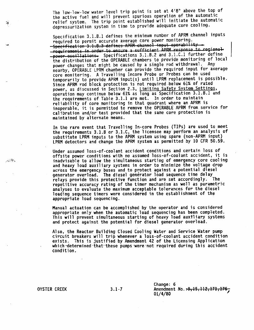
The low-low-low water level trip point is set at 4'8" above the top of
the active fuel and will prevent spurious operation of the automatic
relief system. The trip point established will initiate the automatic
depressurization system in time to provide adequate core cooling.
Specification 3.1.B.1 defines the minimum number of APRM channel inputs
required to permit accurate average core power monitoring.
Speefietien 34.B..3 defines APRM ehanncl input operability regLiremlnts in order to ....r. a su.ffirien. APPM . eso. .. to reqiona4.
power occi!!atiaeA Specifications 3.1.B.2 and 3.1.C.1 further define
the distribution of the OPERABLE chambers to provide monitoring of local
power changes that might be caused by a single rod withdrawal. Any
nearby, OPERABLE LPRM chamber can provide the required input for average
core monitoring. A Travelling Incore Probe or Probes can be used temporarily to provide APRM input(s) until LPRM replacement is possible. Since APRM rod block protection is not required below 61% of rated power, as discussed in Section 2.3, Limiting Safety System Settings, operation may continue below 61% as long as Specification 3.1.B.1 and the requirements of Table 3.1.1 are met. In order to maintain reliability of core monitoring in that quadrant where an APRM is inoperable, it is permitted to remove the OPERABLE APRM from service for calibration and/or test provided that the same core protection is maintained by alternate means.
In the rare event that Travelling In-core Probes (TIPs) are used to meet the requirements 3.1.B or 3.1.C, the licensee may perform an analysis of substitute LPRM inputs to the APRM system using spare (non-APRM input) LPRM detectors and change the APRM system as permitted by 10 CFR 50.59.
Under assumed loss-of-coolant accident conditions and certain loss of offsite power conditions with no assumed loss-of-coolant accident, it is inadvisable to allow the simultaneous starting of emergency core cooling and heavy load auxiliary systems in order to minimize the voltagedrop across the emergency buses and to protect against a potential diesel generator overload. The diesel generator load sequence time delay relays provide this protective function and are set accordingly. The repetitive accuracy rating of the timer mechanism as well as parametric analyses to evaluate the maximum acceptable tolerances for the diesel loading sequence timers were considered in the establishment of the appropriate load sequencing.
Manual actuation can be accomplished by the operator and is considered appropriate only when the automatic load sequencing has been completed. This will prevent simultaneous start.ing of heavy load auxiliary systems and protect against the potential for diesel generator overload.
Also, the Reactor Building Closed Cooling Water and Service Water pump circuit breakers will trip whenever a loss-of-coolant accident condition exists. This is justified by Amendment 42 of the Licensing Application which-determined that--these pumpswere-not required during this accident condition.
Change: 6 OYSTER CREEK 3.1-7 Amendment No.- 9,15,112,171,1 6
01/4/80

C.
...- d...t ,,..it ter I3 t ., . "c.7 C _., .i....t... in the k.AJLP. shall be greta er -ea l i......
When APRM status changes due to instrument failure (APRM or LPRM input failure), the MCPR requirement for the degraded condition shall be met within a time interval of eight (8) hours, provided that the control rod block is placed in operation during this interval.
For core flows other than rated, the nominal value for MCPR shall be increased by a factor of kf, where kf is as shown in the COLR.
If at any time during POWER OPERATION it is determined bynormal surveillance that the limiting value for MCPR is being exceeded for reasons other than instrument failure, action shall be initiated to restore operation to within the prescribed limits. If the steady state MCPR is not returned to within the prescribed limits within two [2] hours, action shall be initiated to bring the reactor to the COLD SHUTDOWN CONDITION within 36 hours. During this period, surveillance and corresponding action shall continue until reactor operation is within the prescribed limit at which time POWER OPERATION may be continued.
OYSTER CREEK Amendment No.: 48,75,111,129,1-,176j 29212
3.10-2
Minimum CRITICAL POWER RATIO (MCPR)
During steady state POWER OPERATION the minimum CRITICAL POWER RATIO (MCPR) shall be equal to or greater than the MCPR limit as specified in the COLR.
• • .oJ•" 1l * .| f"a,,'%T ar•a ! |• | S..... •L - I} • t hf%
o -

Bases:
The Specification for AVERAGE PLANAR LHGR assures that the peak cladding temperature following the postulated design basis loss-of-coolant accident will not exceed the 2200*F limit specified in 10 CFR 50.46. The analytical methods and assumptions used in evaluating the fuel design limits are presented in FSAR Chapter 4.
LOCA analyses are performed for each fuel design at selected exposure points to determine APLHGR limits that meet the PCT and maximum oxidation limits of 10 CFR 50.46. The analysis is performed using GE calculational models which are consistent with the requirements of 10 CFR 50, Appendix K.
The PCT following a postulated LOCA is primarily a function of the average heat generation rate of all the rods of a fuel assembly at any axial location and is not strongly influenced by the rod to rod power distribution within an assembly. Since expected location variations in power distribution within a fuel assembly affect the calculated peak clad temperature by less than + 20°F relative to the peak temperature for a typical fuel design, the limit on the average linear heat generation rate is sufficient to assure that calculated temperatures are below the limits specified in 10 CFR 50.46.
The maximum AVERAGE PLANAR LHGR limits for the various fuel types currently being used are provided in the COLR. The COLR includes MAPLHGR limits for five loop operation. Additional limits on MAPLHGR for operations with less than five loops are given in Specification 3.3.F.2.
Fuel design evaluations are performed to demonstrate that the cladding 1% plastic strain and other fuel design limits are not exceeded during anticipated operational occurrences for operation with LHGRs up to the operating limit LHGR.
The analytical methods and assumptions used in evaluating the anticipated operational occurrences to establish the operating limit MCPR are presented in the FSAR, Chapters 4, 6 and 15 and in Technical Specification 6.9.1 .f. To assure that the Safety Limit MCPR is not exceeded during any moderate frequency transient event, limiting transients have been analyzed to determine the largest reduction in CRITICAL POWER RATIO (CPR). The types of transients evaluated are pressurization, positive reactivity insertion and coolant temperature decrease. The operational MCPR limit is selected to provide margin to accommodate transients and uncertainties in monitoring the core operating state, manufacturing, and in the critical power correlation itself. This limit is derived by addition of the CPR for the most limiting transient to the safety limit MCPR designated in Specification 2. 1.
A o 1.49 has been established for the operating limit MCPR value to rovid ent margin to the MCPR sale~t-y- . .~~b event of reactor thermal-h ility. The 1.49 limit will be considered against the minimum operatin ed on reload transient and accident analysis. The higher of core stabili ransient and accident det'ermine ilb sdt eemn Sthe cycle imit.
OYSTER CREEK 3.10-3 Amendment No.: 48,75,1 11,i29,144, .,6,192, 212,
r

The APRM response is used to predict when the rod block occurs in the analysis of the rod withdrawal
error transient. The transient rod position at the rod block and corresponding MCPR can be determined.
The MCPR has been evaluated for different APRM responses which would result from changes in the
APRM status as a consequence of bypassed APRM channel and/or failed/bypassed LPRM inputs. The
steady state MCPR required to protect the minimum transient CPR for the worst case APRM status
condition (APRM Status 1) is determined in the rod withdrawal error transient analysis. The steady
state MCPR values for APRM status conditions 1, 2, and 3 will be evaluated each cycle. For those cycles where the rod withdrawal error transient is not the most severe transient the MCPR value for APRM status conditions 1, 2, and 3 will be the same and be equal to the limiting transient MCPR value.
The time interval of Eight (8) hours to adjust the steady state of MCPR to account for a degradation in the APRM status is justified on the basis of instituting a control rod block which precludes the possibility of experiencing a rod withdrawal error transient since rod withdrawal is physically prevented. This time interval is adequate to allow the operator to either increase the MCPR to the appiopriate value or to upgrade the status of the APRM system while in a condition which prevents the possibility of this transient occurring.
Transients analyzed each fuel cycle will be evaluated with respect to the operational MCPR limit specified in the COLR.
The purpose of the kr factor is to define operating limits at other than rated flow conditions. At less than 100% flow the required MCPR is the product of the operating limit MCPR and the kf factor. Specifically, the kf factor provides the required thermal margin to protect against a flow increase transient.
The kf factor curves, as shown in the COLR, were developed generically using the flow control line corresponding to rated thermal power at rated core flow. For the manual flow control mode, the kf factors were calculated such that at the maximum flow state (as limited by the pump scoop tube set point) and the corresponding core power (along.the rated flow control line), the limiting bundle's relative power was adjusted until the MCPR was slightly above the-Safety Limit. Using this relative bundle power, the MCPR's were calculated at different points along the rated flow control line corresponding to different core flows. The ratio of the MCPR calculated at a given point of core flow, divided by the operating limit MCPR determines the value of kf.
TAe fAmfra~ rv-e *e re, Io;,c -H ed f& n --oto s ael( a~c4 Alst rmcfor~ +ke.%1di#%a~c jrif~Jtst Ih4j ,T71k k., Ad,,Cfr
O4i, 1Xerai./ 4 r,(Ja~/c (A rf- -c" ~r
tlichZ ssfe-t L- ; LA,ý,Cji &x tl nt 4e e)C-ce
OYSTER CREEK 3.10-4 Amendment No.: 75, 129, 147, 176,192,.2,-