owner’smwith installation instructionsanual - banks...
TRANSCRIPT
109/20/12 PN 96448 v.12.0
Banks Six-Gun®
Diesel Tuner 2003-2004 (235 HP, 250 HP and 305 HP) Dodge 5.9L Cummins (24-valve) ISB Pickup Trucks THIS MANUAL IS FOR USE WITH SYSTEMS 49525, 49526, 49527, 49528, 49530 , 49531, 62977 & 62978
Gale Banks Engineering 546 Duggan Avenue • Azusa, cA 91702 (626) 969-9600 • Fax (626) 334-1743
Product Information & Sales: (888) 635-4565customer Support: (888) 839-5600 Installation Support: (888) 839-2700
bankspower.com
©2012 Gale Banks Engineering
Owner’sManualwith Installation instructions
2 96448 v.12.0
Banks iQ System(P/N 61148-61149)Note: Must upgrade Six-Gun tuner to 63726 to use with Banks iQ.
- 5” touchscreen interface that can control the Banks Diesel Tuner on the fly.
- Interchangable gauge display, read and clear codes, monitor engine diagnostics, log data, time your vehicles runs and much more.
Banks Monster® Exhaust SystemSingle (P/N 48640-48643, 48700, 48701, 48708) Duals (P/N 48702-48707, 48709) Sport (P/N 48777-48780)
- Increases exhaust flow, cuts backpressure, lowers exhaust gas temperatures (EGTs) and increases power.
Banks Ram-Air Intake System(P/N 42145)
- Increases your airflow over stock. - Adds power, improves fuel economy, lowers EGTs and reduces smoke.
Banks Ram-Air Intake Super-Scoop(P/N 42190-42191)
- Adds cooler denser air to the Ram-Air Intake housing, further increasing fuel economy, reducing smoke and lowers EGTs.
Banks Monster-Ram(P/N 42765-42766)
- Increased flow from intercooler- Raises boost without increasing
backpressure at the turbine
Big Hoss Intake Manifold System(P/N 42747)
- Increases flow and provides more uniform air distribution to the engine for more available power at a given boost level.
Banks Exhaust Brake (P/N 55222-55229)
- Increases the stopping power of your truck and extends the service life of your brakes
Banks SmartLock(P/N 55270)
- Reduces wear on transmission - Locks Torque converter and raises
trans-line pressure- Works with Banks Exhaust Brake
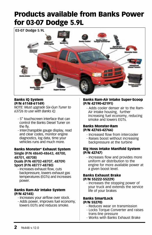
Products available from Banks Power for 03-07 Dodge 5.9L03-07 Dodge 5.9L
96448 v.12.0 3
Boost and Pyro Gauges (P/N 64507)
- Keep your engine safe by monitoring vital engine parameters.
Banks Billet Torque Converter(P/N 72515)
- Higher torque capacity over stock- Lockup clutch is slip-resistant so transmission fluids stay cooler and transmission life is prolonged.
Banks Bullet(P/N 66522-66523)
- Adds power safely to your vehicle- Displays critical engine functions- Engine safeguards- change power levels on-the-fly
Banks Techni-Cooler® System(P/N 25980-25981)
- Provides increased air flow to the engine by increasing air density for more increased power, lower EGTs and improved fuel economy.
Thermocouple- Add a temperature limiting function to your Diesel Tuner.
Banks BigHead® Actuator(P/N 24331)
- Achieves a higher peak boost over stock and gives you precise boost control that gives you crisp acceleration and more mid-range pulling power.
Banks Stinger Systems(P/N 49692-49699, 49708-49711, 49716-49721)Contains:
- Ram-Air Intake system- Monster Exhaust (single or dual)- EconoMind Tuner w/ Banks iQ- Big Head Wastegate Actuator
Banks PowerPack Systems(P/N 49700-49707, 49712-49715, 49722-49727)Contains:
- Ram-Air Intake system- Monster Exhaust (single or dual)- EconoMind Tuner w/ Banks iQ- Big Head Wastegate Actuator- Monster-Ram- Techni-cooler System
Banks Six-Gun Bundle(P/N 49728-49735, 49744-49747, 49752-49757)Contains:
- Ram-Air Intake system- Monster Exhaust (single or dual)- Six-Gun Tuner w/ Banks iQ- Big Head Wastegate Actuator
Banks Big Hoss Bundle(P/N 49736-49743, 49748-49751, 49758-49763)Contains:
- Ram-Air Intake system- Monster Exhaust (single or dual)- Six-Gun Tuner w/ Banks iQ- Big Head Wastegate Actuator- Monster-Ram- Techni-cooler System
For More Information please call (888) 635-4565or Visit us online @ www.bankspower.com
4 96448 v.12.0
THIS IS A HIGH PERFORMANCE PRODUCT. USE AT YOUR OWN RISK.
Do not use this product until you have carefully read the following agreement.
This sets forth the terms and conditions for the use of this product. The installation of this product indicates that the BUYER has read and understands this agreement and accepts its terms and conditions.
DISCLAIMER OF LIABILITYGale Banks Engineering Inc., and its distributors, employees, and dealers (hereafter “SELLER”) shall in no way be responsible for the product’s proper use and service. The BUYER hereby waives all liability claims.
The BUYER acknowledges that he/she is not relying on the SELLER’s skill or judgment to select or furnish goods suitable for any particular purpose and that there are no liabilities which extended beyond the description on the face hereof and the BUYER hereby waives all remedies or liabilities, expressed or implied, arising by law or otherwise, (including without any obligations of the SELLER with respect to fitness, merchantability, and consequential damages) whether or not occasioned by the SELLER’s negligence.
The BUYER is responsible to fully understand the capability and limitations of his/her vehicle according to manufacturer specifications and agrees to hold the SELLER harmless from any damage resulting from the failure to adhere to such specifications.
The SELLER disclaims any warranty and expressly disclaims any liability for personal injury or damages. The BUYER acknowledges and agrees that the disclaimer of any liability for personal injury is a material term for this agreement and the BUYER aggress to indemnify the SELLER and to hold the SELLER harmless from any claim related to the item of the equipment purchased. Under no circumstances will the SELLER be liable for any damages or expenses by reason of the use or sale of any such equipment.
The BUYER is responsible to obey all applicable federal, state, and local laws, statutes, and ordinances when operating his/her vehicle, and the BUYER agrees to hold SELLER harmless from any violation thereof.
The SELLER assumes no liability regarding the improper installation or misapplication of its products. It is the installer’s responsibility to check for proper installation and if in doubt, contact the manufacturer.
The BUYER is solely responsible for all warranty issues from the automotive manufacturer.
LIMITATION OF WARRANTYGale Banks Engineering Inc., (hereafter “SELLER”) gives Limited Warranty as to description, quality, merchantability, fitness for any particular purpose, productiveness, or any other matter of SELLER’s product sold herewith. The SELLER shall be in no way responsible for the product’s open use and service and the BUYER hereby waives all rights except those expressly written herein. This Warranty shall not be extended or varied except by written instrument signed by SELLER and BUYER.
Disclaimer of Liability & Warranty
96448 v.12.0 5
The Warranty is Limited to two (2) years from the date of sale and is limited solely to the parts contained within the product’s kit. All products that are in question of Warranty must be returned shipping prepaid to the SELLER and must be accompanied by a dated proof of purchase receipt. All Warranty claims are subject to approval by Gale Banks Engineering Inc.
Under no circumstance shall the SELLER be liable for any labor charged or travel time incurred in diagnosis for defects, removal, or reinstallation of this product, or any other contingent expense.
Under no circumstances will the SELLER be liable for any damage or expenses incurred by reason of the use or sale of any such equipment.
IN THE EVENT THAT THE BUYER DOES NOT AGREE WITH THIS AGREEMENT: THE BUYER MAY PROMPTLY RETURN THIS PRODUCT, IN A NEW AND UNUSED CONDITION, WITH A DATED PROOF OF PURCHASE, TO THE PLACE OF PURCHASE WITHIN THIRTY (30) DAYS FROM DATE OF PURCHASE FOR A FULL REFUND.
THE INSTALLATION OF THIS PRODUCT INDICATES THAT THE BUYER HAS READ AND UNDERSTANDS THIS AGREEMENT AND ACCEPTS ITS TERMS AND CONDITIONS.
Table of ContentsDisclaimer of Liability . . . . . . . . . . . 4& Warranty
General Installation Practices . . . . 6
Section 1 . . . . . . . . . . . . . . . . . . . . . . 9 Six-Gun Diesel Tuner Installation
Section 2 . . . . . . . . . . . . . . . . . . . . 20 Installation of the Six-Gun Power Level Selector Switch
Section 3 . . . . . . . . . . . . . . . . . . . . 23 Optional Thermocouple installation
Section 4 . . . . . . . . . . . . . . . . . . . . 25 Performing Transmission Learning Procedure
Section 5 . . . . . . . . . . . . . . . . . . . . 27 Engine Power Rating Learning Procedure
Section 6 . . . . . . . . . . . . . . . . . . . . 29 checking Engine Performance
Section 7 . . . . . . . . . . . . . . . . . . . . 30 Mounting the Six-Gun Module
Section 8 . . . . . . . . . . . . . . . . . . . . 31 Troubleshooting
Section 9 . . . . . . . . . . . . . . . . . . . . 33 clearing Learned Transmission Procedure
6 96448 v.12.0
The Banks Six-Gun Diesel Tuner has six power levels adjustable by the supplied Six-Gun switch.
Level 1 is stock . Each additional higher level adds approximately 20% of the available power increase.
To prevent damage to the factory transmission, Banks recommends that both automatic and manual transmission vehicles do not exceed Level 4 while the vehicle is experiencing load (towing, climbing a steep grade, carrying a load, etc.).
To use the higher levels of the Six-Gun Diesel Tuner while towing or climbing, airflow improvements must be made to lower the exhaust gas temperature (EGT) entering the turbo. The EGT should not exceed 1350º F for more than a few seconds. Elevated EGT can damage the turbocharger and the engine.
Also, the factory clutch or torque converter will need to be upgraded to an aftermarket unit that can handle the increased torque and horsepower of the higher levels. Failure to upgrade the clutch or torque converter prior to using the upper levels while the vehicle is loaded may result in damage
to the factory clutch or torque. Banks is NOT responsible for clutch, torque converter and/or transmission damage.
Note: Before proceeding with these instructions, please carefully read the DISCLAIMeR oF LIABILItY and LIMItAtIoN oF WARRANtY statement located on page 4 of this manual.
1. For ease of installation of your Banks Six-Gun, familiarize yourself with the procedures by reading the entire manual before starting work.
2. Disconnect the ground cable from the battery before beginning work. If there are two batteries, disconnect both.
3. Route and tie wires and hoses a minimum of 6 inches away from exhaust heat, moving parts and sharp edges. clearance of 8 inches or more is recommended where possible.
4. When raising the vehicle, support it on properly weight-rated safety stands, ramps or a commercial hoist. Follow the manufacturer’s safety precautions. Take care to balance the vehicle to prevent it from slipping or falling. When using ramps, be sure the front wheels are centered squarely on the topsides; put the transmission in park; set the hand brake; and place blocks behind the rear wheels.
CAUTION! Do not use floor jacks to support the vehicle while working under it. Do not raise the vehicle onto concrete blocks, masonry or any other item not intended specifically for this use.
5. The installation should be performed at a time when the vehicle has been allowed to completely cool. This installation requires the installer to work near surfaces that may remain hot after the vehicle has been run.
General Installation Practices
Dear Customer,
If you have any questions concerning the installation of your Banks Six-Gun Diesel Tuner, please call our Technical Service Hotline at (888) 839-2700 between 7:00 am and 5:00 pm (PT). If you have any questions relating to shipping or billing, please contact our Customer Service Department at (888) 839-5600.
Thank you.
96448 v.12.0 7
Failure to allow the vehicle to cool may result in personal injury.
6. During installation, keep your work area and components clean to avoid possible dirt entry into the engine.
7. Save this Owner’s Manual as a reference for system maintenance and service.
8. Banks recommends that a Pyrometer (EGT) gauge and a Boost gauge be installed with the Six-Gun Diesel Tuner to help monitor performance and exhaust gas temperature of the vehicle (see part numbers below). To further increase engine life by lower EGT’s, Banks also recommends installing the following airflow improvements:
Airflow Improvements:1. Banks Monster Exhaust, 235-, 250- and 305-hp Rated Engines Std. cab Long Bed w/ cat. . . 48640 Quad cab Short Bed w/ cat . 48640 Std. cab Long Bed w/o cat. . 48641 Quad cab Short Bed w/o cat 48641 Quad cab Long Bed w/ cat. . 48642 Quad cab Long Bed w/o cat 48643 2. Banks BigHead® Actuator . . . . . 24331 3. Banks Ram-Air® Filter . . . . . . . . . . . . . . . . . . . . 41028 Service Kit. . . . . . . . . . . . . . . . 90094
Gauges:4. Gauge Assembly Boost and Pyro*. . . . . . . . . . . 64507 5. Thermocouple . . . . . . . . . . . . . . 63042 6. Lead wire . . . . . . . . . . . . . . . . . . 63061 7. Turbine Inlet Gasket*. . . . . . . . . 93033 * also available separately
9. For ease of installation of your Six-Gun Diesel Tuner, refer to the Installation Flow chart on page 8 and the Table of contents on page 5 for the necessary steps involved for your specific application.
Tools Required: These tools are necessary for the installation unless otherwise specified.
• 1⁄4” and 3⁄8” drive ratchets with inch and metric sockets including 5⁄16”, 7⁄16” deep 1⁄4” drive sockets and a 1⁄4” drive extension
• Inch and metric combination or open-end wrenches
• Standard and Phillips head screwdrivers
• Standard and needle-nose pliers
• Pocket or X-Acto knife
• Clean shop towels or rags
• Drill motor
• 1⁄8” and 3⁄8” drill bits
• Wire crimping/stripping tool
Tools Required for Optional Speed-Loader Installation:
• 7⁄16” drill bit
• Tap Handle
• 1⁄4” NPT tap
• 12mm, 12-point socket & wrench
Highly recommended tools and supplies:
• Multimeter or 12-volt test light
• Heat gun
8 96448 v.12.0
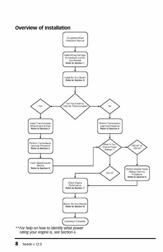
Overview of Installation
** For help on how to identify what power rating your engine is, see Section 6
96448 v.12.0 9
SECTION 1SIx-GUN DIESEL TUNER INSTaLLaTION
For 2003 vehicles, start from Step 1. For 2004 vehicles, start from Step 2.
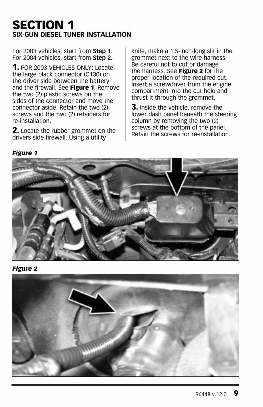
1. FOR 2003 VEHIcLES ONLY: Locate the large black connector (c130) on the driver side between the battery and the firewall. See Figure 1. Remove the two (2) plastic screws on the sides of the connector and move the connector aside. Retain the two (2) screws and the two (2) retainers for re-installation.
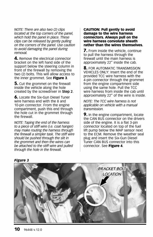
2. Locate the rubber grommet on the drivers side firewall. Using a utility
knife, make a 1.5-inch-long slit in the grommet next to the wire harness. Be careful not to cut or damage the harness. See Figure 2 for the proper location of the required cut. Insert a screwdriver from the engine compartment into the cut hole and thrust it through the grommet.
3. Inside the vehicle, remove the lower dash panel beneath the steering column by removing the two (2) screws at the bottom of the panel. Retain the screws for re-installation.
Figure 1
Figure 2
10 96448 v.12.0
Note: there are also two (2) clips located at the top corners of the panel, which hold the panel in place. these clips can be released by gently pulling on the corners of the panel. Use caution to avoid damaging the panel during removal.
4. Remove the electrical connector bracket on the left hand side of the support below the steering column in front of the firewall by removing the two (2) bolts. This will allow access to the inner grommet. See Figure 3.
5. cut the grommet on the firewall inside the vehicle along the hole created by the screwdriver in Step 2.
6. Locate the Six-Gun Diesel Tuner wire harness end with the 8 and 10-pin connector. From the engine compartment, push this end through the hole cut in the grommet through the firewall.
Note: taping the end of the harness to a piece of stiff wire (i.e. coat hanger) may make routing the harness through the firewall a simpler task. the stiff wire should be pushed through the slit in the grommet and then the wires can be attached to the stiff wire and pulled through the hole in the firewall.
CAUTION: Pull gently to avoid damage to the wire harness connectors. Always pull on the wire harness convolute sheath rather than the wires themselves.
7. From inside the vehicle, continue to pull the harness through the firewall until the main harness is approximately 22” inside the cab.
8. FOR AUTOMATIc TRANSMISSION VEHIcLES ONLY: Insert the end of the provided Tcc wire harness with the 4-pin connector through the grommet from the engine compartment side using the same hole. Pull the Tcc wire harness from inside the cab until approximately 22” of the wire is inside.
Note: the tCC wire harness is not applicable on vehicle with a manual transmission.
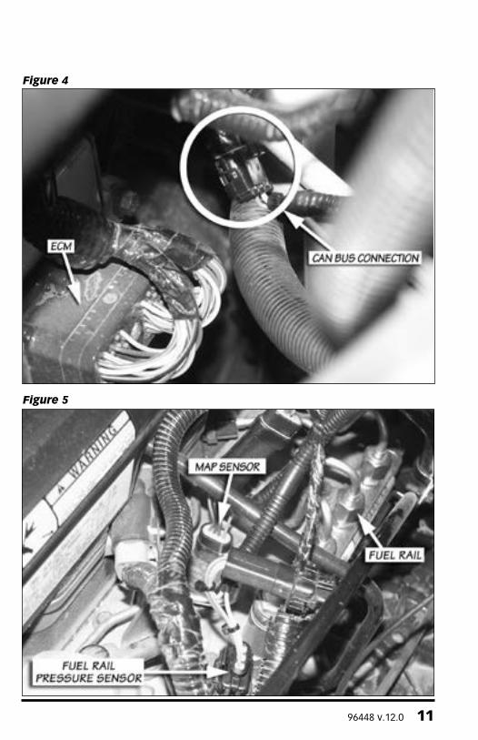
9. In the engine compartment, locate the cAN BUS connector on the drivers side of the engine. It is a flat 3-pin connector located on top of the fuel lift pump below the MAP sensor next to the EcM. Remove the weather seal plug and insert the Six-Gun Diesel Tuner cAN BUS connector into this connector. See Figure 4.
Figure 3
96448 v.12.0 11
Figure 4
Figure 5
12 96448 v.12.0
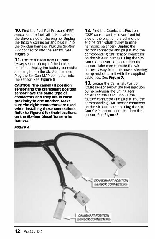
10. Find the Fuel Rail Pressure (FRP) sensor on the fuel rail. It is located on the drivers side of the engine. Unplug the factory connector and plug it into the Six-Gun harness. Plug the Six-Gun FRP connector into the sensor. See Figure 5.
11. Locate the Manifold Pressure (MAP) sensor on top of the intake manifold. Unplug the factory connector and plug it into the Six-Gun harness. Plug the Six-Gun MAP connector into the sensor. See Figure 5.
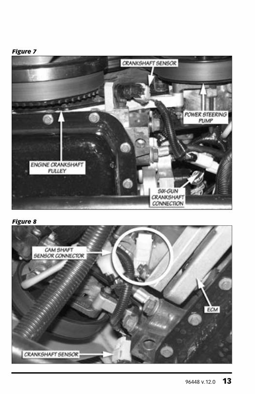
CAUTION: The camshaft position sensor and the crankshaft position sensor have the same type of connectors and they are in close proximity to one another. Make sure the right connectors are used when installing these connections. Refer to Figure 6 for their locations on the Six-Gun Diesel Tuner wire harness.
12. Find the crankshaft Position (cKP) sensor on the lower front left side of the engine. It is behind the engine crankshaft pulley (engine harmonic balancer). Unplug the factory connector and plug it into the corresponding cKP sensor connector on the Six-Gun harness. Plug the Six-Gun cKP sensor connector into the sensor. Take care to route the wire harness away from the power steering pump and secure it with the supplied cable ties. See Figure 7.
13. Locate the camshaft Position (cMP) sensor below the fuel injection pump between the timing gear cover and the EcM. Unplug the factory connector and plug it into the corresponding cMP sensor connector on the Six-Gun harness. Plug the Six-Gun cMP sensor connector into the sensor. See Figure 8.
Figure 6
96448 v.12.0 13
Figure 7
Figure 8
14 96448 v.12.0
Figure 9
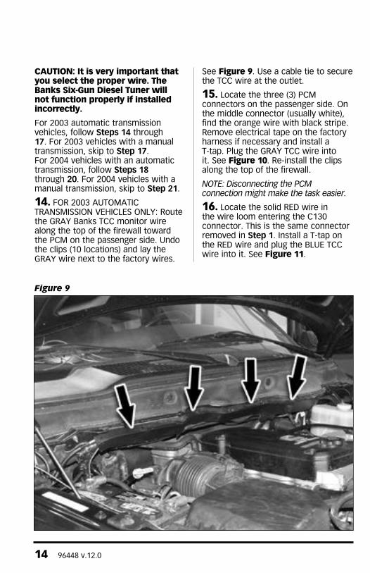
CAUTION: It is very important that you select the proper wire. The Banks Six-Gun Diesel Tuner will not function properly if installed incorrectly.
For 2003 automatic transmission vehicles, follow Steps 14 through 17. For 2003 vehicles with a manual transmission, skip to Step 17. For 2004 vehicles with an automatic transmission, follow Steps 18 through 20. For 2004 vehicles with a manual transmission, skip to Step 21.
14. FOR 2003 AUTOMATIc TRANSMISSION VEHIcLES ONLY: Route the GRAY Banks Tcc monitor wire along the top of the firewall toward the PcM on the passenger side. Undo the clips (10 locations) and lay the GRAY wire next to the factory wires.
See Figure 9. Use a cable tie to secure the Tcc wire at the outlet.
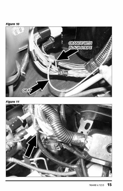
15. Locate the three (3) PcM connectors on the passenger side. On the middle connector (usually white), find the orange wire with black stripe. Remove electrical tape on the factory harness if necessary and install a T-tap. Plug the GRAY Tcc wire into it. See Figure 10. Re-install the clips along the top of the firewall.
Note: Disconnecting the PCM connection might make the task easier.
16. Locate the solid RED wire in the wire loom entering the c130 connector. This is the same connector removed in Step 1. Install a T-tap on the RED wire and plug the BLUE Tcc wire into it. See Figure 11.
96448 v.12.0 15
Figure 11
Figure 10
16 96448 v.12.0
Figure 12
Figure 13A
96448 v.12.0 17
17. FOR ALL 2003 VEHIcLES ONLY: Locate the LIGHT GREEN wire with BLAcK stripe in the wire loom entering the c130 connector. This is the same connector removed in Step 1. Install a T-tap on this wire. Plug the red Six-Gun Diesel Tuner wire into this T-tap. Tie the excess RED wire to the wire harness using the supplied cable ties. Skip to Step 22.
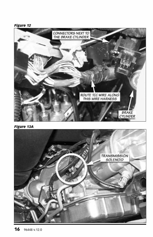
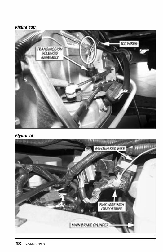
18. FOR 2004 AUTOMATIc TRANSMISSION VEHIcLES ONLY: Plug the TCC extension into the BLUE Tcc wire. Using the wire harness on the two (2) connectors next to the main brake cylinder as a guide (see Figure 12), route the BLUE and gray Tcc wires toward the transmission solenoid assembly that is sitting on the transmission. It is located underneath the drivers side of the vehicle. See Figure 13A. Secure the wire using cable ties along the way.
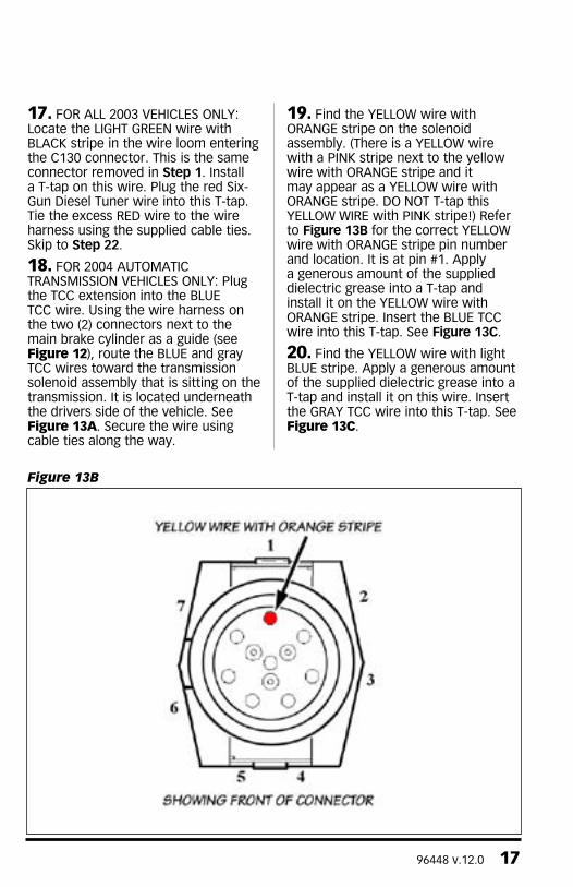
19. Find the YELLOW wire with ORANGE stripe on the solenoid assembly. (There is a YELLOW wire with a PINK stripe next to the yellow wire with ORANGE stripe and it may appear as a YELLOW wire with ORANGE stripe. DO NOT T-tap this YELLOW WIRE with PINK stripe!) Refer to Figure 13B for the correct YELLOW wire with ORANGE stripe pin number and location. It is at pin #1. Apply a generous amount of the supplied dielectric grease into a T-tap and install it on the YELLOW wire with ORANGE stripe. Insert the BLUE Tcc wire into this T-tap. See Figure 13C.
20. Find the YELLOW wire with light BLUE stripe. Apply a generous amount of the supplied dielectric grease into a T-tap and install it on this wire. Insert the GRAY Tcc wire into this T-tap. See Figure 13C.
Figure 13B
18 96448 v.12.0
Figure 13C
Figure 14
96448 v.12.0 19
21. FOR ALL 2004 VEHIcLES ONLY: Locate the two (2) electrical connectors next to the main brake cylinder. Find the pink wire with gray stripe on the connector closest to the brake cylinder. Install a T-tap on this wire. Plug the Six-Gun Diesel Tuner red wire into the T-tap. See Figure 14.
22. Inside the cab, plug the main 8- and 10-pin connectors from the wire loom into the front of the Six-Gun Diesel Tuner box. On vehicles with automatic transmissions, plug the 4-pin Tcc wire harness connector into the rear of the Six-Gun Diesel Tuner box.
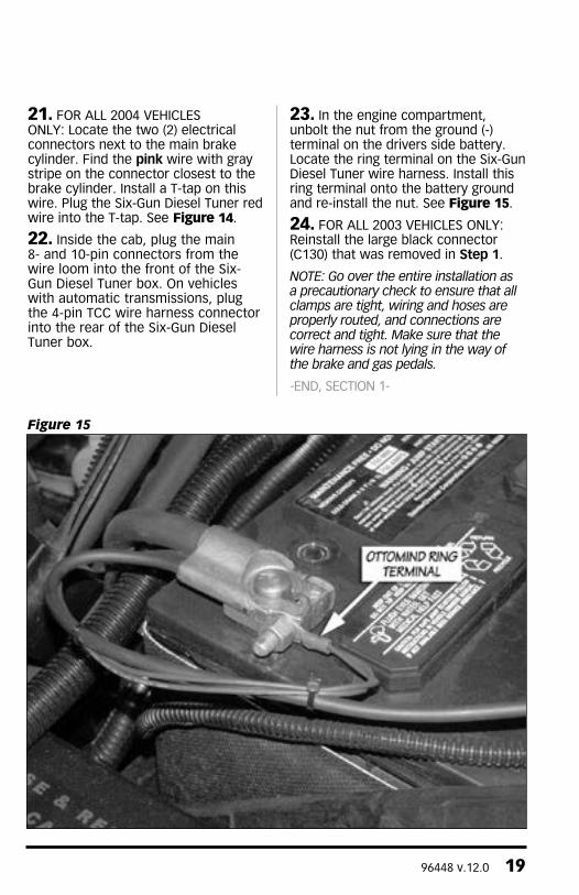
23. In the engine compartment, unbolt the nut from the ground (-) terminal on the drivers side battery. Locate the ring terminal on the Six-Gun Diesel Tuner wire harness. Install this ring terminal onto the battery ground and re-install the nut. See Figure 15.
24. FOR ALL 2003 VEHIcLES ONLY: Reinstall the large black connector (c130) that was removed in Step 1.
Note: Go over the entire installation as a precautionary check to ensure that all clamps are tight, wiring and hoses are properly routed, and connections are correct and tight. Make sure that the wire harness is not lying in the way of the brake and gas pedals.
-END, SEcTION 1-
Figure 15
20 96448 v.12.0
CAUTION: Do not use force when working on plastic parts. Permanent damage to the part might result.
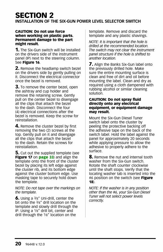
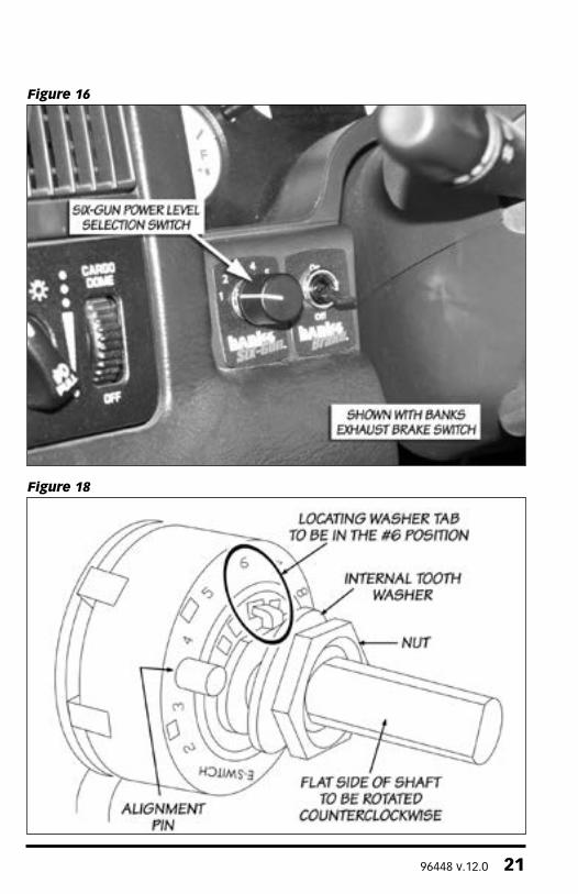
1. The Six-Gun switch will be installed on the drivers side of the instrument panel (IP) next to the steering column. See Figure 16.
2. Remove the headlamp switch bezel on the drivers side by gently pulling on it. Disconnect the electrical connector once the bezel is removed.
3. To remove the center bezel, open the ashtray and cup holder and remove the retaining screw. Gently pull on the center bezel to disengage all the clips that attach the bezel to the dash. Disconnect the four (4) electrical connections after the bezel is removed. Keep the screw for reinstallation.
4. Remove the cluster bezel by first removing the two (2) screws at the top. Gently pull on it and disengage all the clips that attach the bezel to the dash. Retain the screws for reinstallation.
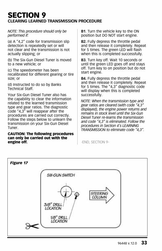
5. cut out the supplied template (see Figure 17 on page 33) and align the template onto the front of the cluster bezel by placing its left edge against the cluster rib, and its bottom edge against the cluster bottom edge. Use masking tape to securely hold down the template.
Note: Do not tape over the markings on the template.
6. Using a 3⁄8” Uni-drill, center the bit onto the 3⁄8” drill location on the template and slowly drill through the IP. Using a 1⁄8” drill bit, center and drill through the 1⁄8” location on the
template. Remove and discard the template and any plastic shavings.
Note: It is important that the hole is drilled at the recommended location. the switch may not clear the instrument panel structure if the hole is shifted to another location.
7. Align the Banks Six-Gun label onto the previously drilled hole. Make sure the entire mounting surface is clean and free of dirt and oil before mounting the label. clean and dry as required using a cloth dampened with rubbing alcohol or similar cleaning solution.
CAUTION: Do not spray fluid directly onto any electrical equipment, or equipment damage may result.
Mount the Six-Gun Diesel Tuner switch label onto the cluster by peeling the protective backing off the adhesive tape on the back of the switch label. Hold the label against the panel for approximately 20 seconds while applying pressure to allow the adhesive to properly adhere to the surface.
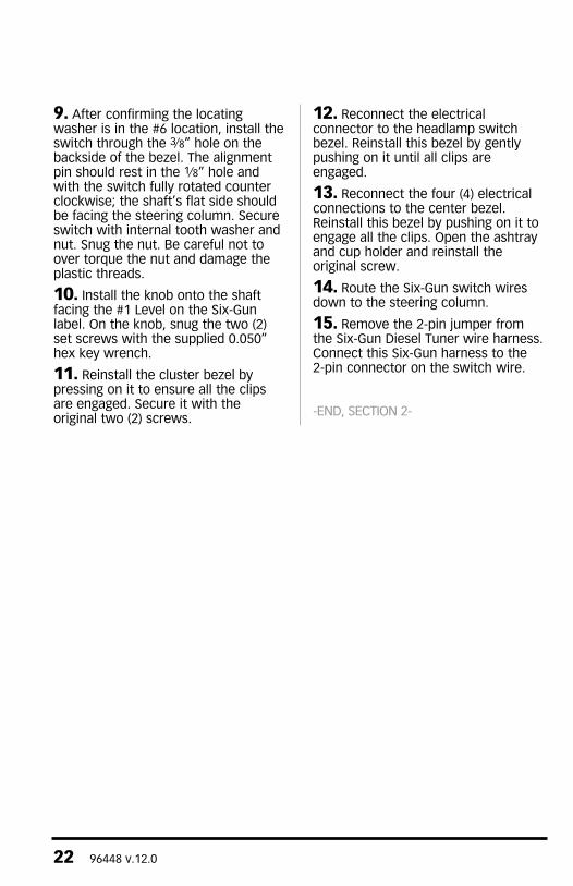
8. Remove the nut and internal tooth washer from the Six-Gun switch. Rotate the shaft counter clockwise until the shaft stops. Verify that the locating washer tab is inserted into the #6 position on the switch (see Figure 18).
Note: If the washer is in any position other than the #6, your Six-Gun Diesel tuner will not select power levels correctly.
SECTION 2INSTaLLaTION OF THE SIx-GUN POWER LEVEL SELECTOR SWITCH
96448 v.12.0 21
Figure 16
Figure 18
22 96448 v.12.0
9. After confirming the locating washer is in the #6 location, install the switch through the 3⁄8” hole on the backside of the bezel. The alignment pin should rest in the 1⁄8” hole and with the switch fully rotated counter clockwise; the shaft’s flat side should be facing the steering column. Secure switch with internal tooth washer and nut. Snug the nut. Be careful not to over torque the nut and damage the plastic threads.
10. Install the knob onto the shaft facing the #1 Level on the Six-Gun label. On the knob, snug the two (2) set screws with the supplied 0.050” hex key wrench.
11. Reinstall the cluster bezel by pressing on it to ensure all the clips are engaged. Secure it with the original two (2) screws.
12. Reconnect the electrical connector to the headlamp switch bezel. Reinstall this bezel by gently pushing on it until all clips are engaged.
13. Reconnect the four (4) electrical connections to the center bezel. Reinstall this bezel by pushing on it to engage all the clips. Open the ashtray and cup holder and reinstall the original screw.
14. Route the Six-Gun switch wires down to the steering column.
15. Remove the 2-pin jumper from the Six-Gun Diesel Tuner wire harness. Connect this Six-Gun harness to the 2-pin connector on the switch wire.
-END, SEcTION 2-
96448 v.12.0 23
If the thermocouple is not being installed, skip to Section 4, tRANSMISSIoN LeARNING PRoCeDURe on page 25.
Note: the thermocouple is not required to operate the Six-Gun.
1. The thermocouple monitors the temperature of the exhaust gases entering the turbocharger at the turbine housing. Installation requires that the exhaust manifold be drilled near the outlet of the manifold adjacent to the turbine housing. For this reason it is essential that the turbocharger be removed from the engine in order to clean out any metal chips from drilling that could cause turbine blade damage.
The cummins ISB engine uses a divided exhaust manifold. The thermocouple may be installed to sample exhaust temperature in either exhaust passage. We recommend the rear passage (toward the firewall).
2. Loosen the clamps that attach the air inlet tube to the air filter housing and to the turbocharger, and remove the air inlet tube from the vehicle. Remove the air filter housing from the vehicle. This will allow easier access to the turbocharger.
3. Loosen the upper hose clamp on the turbocharger oil drain-tube hose that is located between the two sections of the oil drain tube.
4. Disconnect the oil supply hose at the turbocharger. Disconnect the compressor outlet hose that goes to the intercooler.
5. Remove the turbine outlet pipe by loosening the V-band. Save V-band for re-installation.
6. Remove the turbocharger mounting nuts/bolts and the turbocharger from the exhaust manifold. Clean and inspect the exhaust flange mounting surfaces on the exhaust manifold. Make
sure the surface is clean and dry.
CAUTION: Anytime the turbocharger is removed from the engine, take care that no foreign objects enter any of the turbocharger connections on the engine or the turbocharger. Foreign objects entering air, exhaust, or oil connections may cause major damage to the engine and/or turbocharger and is not covered under any warranty. Cover the open end of the intercooler pipe with a clean rag, as this pipe is very suscep-tible to foreign object entry.
7. Stuff clean shop towels into the compressor outlet and inlet hoses to prevent contamination from entering the pipes. cover the turbo oil drain pipe to avoid contamination.
8. Stuff a small clean shop towel or rag 4 to 5 inches into the rear exhaust manifold passage through the turbocharger mounting flange. This is to prevent chips from entering the manifold while drilling and tapping.
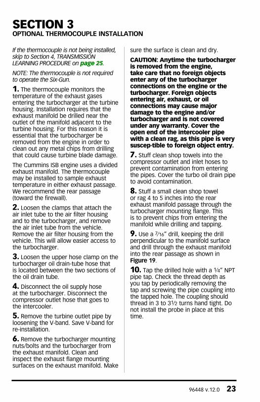
9. Use a 7⁄16” drill, keeping the drill perpendicular to the manifold surface and drill through the exhaust manifold into the rear passage as shown in Figure 19.
10. Tap the drilled hole with a 1⁄4” NPT pipe tap. check the thread depth as you tap by periodically removing the tap and screwing the pipe coupling into the tapped hole. The coupling should thread in 3 to 31⁄2 turns hand tight. Do not install the probe in place at this time.
SECTION 3OPTIONaL THERMOCOUPLE INSTaLLaTION
24 96448 v.12.0
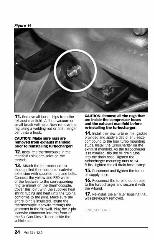
11. Remove all loose chips from the exhaust manifold. A shop vacuum or small brush will help. Now remove the rag using a welding rod or coat hanger bent into a hook.
CAUTION! Make sure rags are removed from exhaust manifold prior to reinstalling turbocharger!
12. Install the thermocouple in the manifold using anti-seize on the threads.
13. Attach the thermocouple to the supplied thermocouple leadwire extension with supplied nuts and bolts. connect the yellow and RED wires of the leadwire to the corresponding ring terminals on the thermocouple. cover this joint with the supplied heat shrink tubing and heat until the tubing conforms to the joint. Make sure the entire joint is insulated. Route the thermocouple leadwire through the grommet in the firewall. Plug the 2-pin leadwire connector into the front of the Six-Gun Diesel Tuner inside the vehicle cab.
CAUTION: Remove all the rags that are inside the compressor hoses and the exhaust manifold before re-installing the turbocharger.
14. Install the new turbine inlet gasket provided and apply a dab of anti-seize compound to the four turbo mounting studs. Install the turbocharger on the exhaust manifold. As the turbocharger is reinstalled, slip the oil drain tube into the drain hose. Tighten the turbocharger mounting nuts to 24 ft-lbs. Tighten the oil drain hose clamp.
15. Reconnect and tighten the turbo oil supply hose.
16. Reconnect the turbine outlet pipe to the turbocharger and secure it with the V-band.
17. Re-install the air filter housing that was previously removed.
-END, SEcTION 3-
Figure 19
96448 v.12.0 25
Your Six-Gun Diesel Tuner displays the “4,3” diagnostic code (refer to TROUBLESHOOTING in Section 9 on how to read codes) when it needs to learn your transmission configurations. This always occurs when the Six-Gun Diesel Tuner is first installed on the truck.
Banks Six-Gun Diesel Tuner is equipped with advanced safety features to preserve your automatic transmission. One of them is the capability to detect the occurrence of transmission slip, and it will automatically de-rate the engine output power accordingly. Before this safety feature can take effect, the Six-Gun Diesel Tuner needs to learn that your truck is equipped with an automatic transmission. (Please read the “Disclaimer of Liability” on page 4.)
1. Reconnect all battery terminals.
The following driving test shall be performed in an area where speeds of this nature are safe and traffic is light. For vehicle with a manual transmission, follow Steps 2 through 3. For vehicle with automatic transmission, follow Steps 4 through 6.
While driving, listen for any exhaust leaks or rattles, or intake boost leaks. After the engine cools, re-tighten clamps and hoses if leaks are detected.
2. To teach the Six-Gun Diesel Tuner that your truck is equipped with a manual transmission, drive the truck at a vehicle speed of over 50 mph for at least 2 minutes. The “4,3” diagnostic code will be eliminated.
3. If a Speed-Loader is being installed, go to Section 5, “SPEED-LOADER MODULE INSTALLATION” on page 26 and follow the procedure; otherwise proceed to Section 6, “ENGINE POWER RATING LEARNING PROcEDURE” on page 27. Repeat Step 2 if necessary to eliminate code.
4. To teach the Six-Gun Diesel Tuner that your truck is equipped with an automatic transmission, drive your truck under light load with overdrive turned on (4th gear). Obtain a vehicle speed of over 60 mph until torque converter is locked (the torque converter is usually locked at speeds over 60 mph). Maintain this speed steadily with the torque converter locked for at least 30 seconds.
5. continue to drive. Slow down and turn off overdrive and obtain vehicle speed of over 50 mph until torque converter is locked (with overdrive off the torque converter is usually locked at speeds over 50 mph). Maintain the speed steadily with the torque converter locked for at least 30 seconds.
6. Once the transmission is learned, the “4,3” diagnostic code will be eliminated. If a Speed-Loader is being installed, go to Section 5, “SPEED-LOADER MODULE INSTALLATION” on page 26 and follow the procedure, otherwise proceed to Section 6, “LEARNING ENGINE POWER RATING” on page 27. If the code is not eliminated, repeat Steps 4 to 5.
-END, SEcTION 4-
SECTION 4TRaNSMISSION LEaRNING PROCEDURE

26 96448 v.12.0
LEFT INTENTIONALLY BLANK
96448 v.12.0 27
To be performed on part number 62977 only. If installing part number 62979, skip to section 7 on page 29.
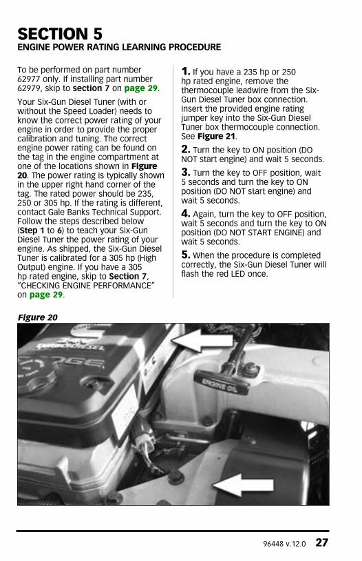
Your Six-Gun Diesel Tuner (with or without the Speed Loader) needs to know the correct power rating of your engine in order to provide the proper calibration and tuning. The correct engine power rating can be found on the tag in the engine compartment at one of the locations shown in Figure 20. The power rating is typically shown in the upper right hand corner of the tag. The rated power should be 235, 250 or 305 hp. If the rating is different, contact Gale Banks Technical Support. Follow the steps described below (Step 1 to 6) to teach your Six-Gun Diesel Tuner the power rating of your engine. As shipped, the Six-Gun Diesel Tuner is calibrated for a 305 hp (High Output) engine. If you have a 305 hp rated engine, skip to Section 7, “cHEcKING ENGINE PERFORMANcE” on page 29.
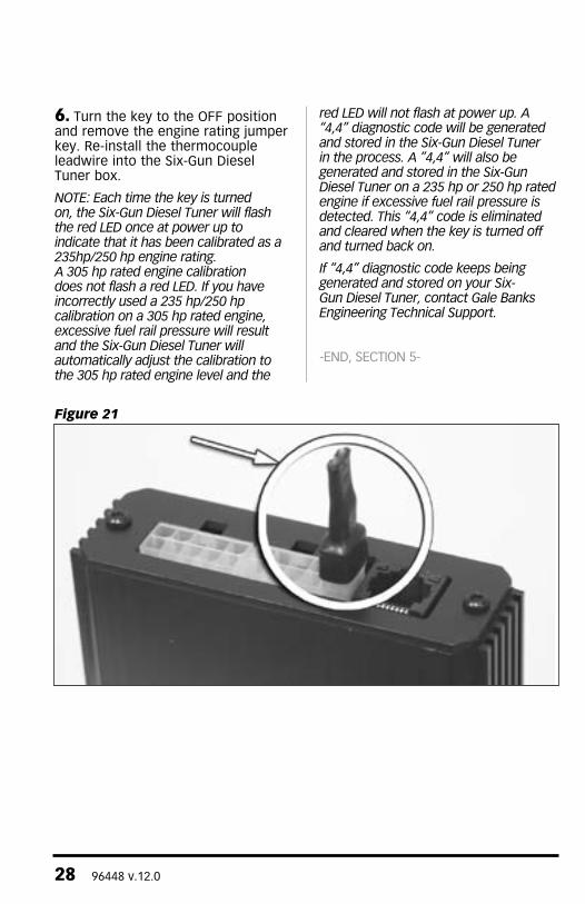
1. If you have a 235 hp or 250 hp rated engine, remove the thermocouple leadwire from the Six-Gun Diesel Tuner box connection. Insert the provided engine rating jumper key into the Six-Gun Diesel Tuner box thermocouple connection. See Figure 21.
2. Turn the key to ON position (DO NOT start engine) and wait 5 seconds.
3. Turn the key to OFF position, wait 5 seconds and turn the key to ON position (DO NOT start engine) and wait 5 seconds.
4. Again, turn the key to OFF position, wait 5 seconds and turn the key to ON position (DO NOT START ENGINE) and wait 5 seconds.
5. When the procedure is completed correctly, the Six-Gun Diesel Tuner will flash the red LED once.
SECTION 5ENGINE POWER RaTING LEaRNING PROCEDURE
Figure 20
28 96448 v.12.0
6. Turn the key to the OFF position and remove the engine rating jumper key. Re-install the thermocouple leadwire into the Six-Gun Diesel Tuner box.
Note: each time the key is turned on, the Six-Gun Diesel tuner will flash the red LeD once at power up to indicate that it has been calibrated as a 235hp/250 hp engine rating. A 305 hp rated engine calibration does not flash a red LeD. If you have incorrectly used a 235 hp/250 hp calibration on a 305 hp rated engine, excessive fuel rail pressure will result and the Six-Gun Diesel tuner will automatically adjust the calibration to the 305 hp rated engine level and the
red LeD will not flash at power up. A “4,4” diagnostic code will be generated and stored in the Six-Gun Diesel tuner in the process. A ”4,4” will also be generated and stored in the Six-Gun Diesel tuner on a 235 hp or 250 hp rated engine if excessive fuel rail pressure is detected. this “4,4” code is eliminated and cleared when the key is turned off and turned back on.
If “4,4” diagnostic code keeps being generated and stored on your Six-Gun Diesel tuner, contact Gale Banks engineering technical Support.
-END, SEcTION 5-
Figure 21
96448 v.12.0 29
Note: the Six-Gun Diesel tuner requires the engine coolant temperature (eCt) to be above 125º before it will add fuel.
Note: this verification of proper performance should be performed prior to permanent mounting of the Six-Gun Diesel tuner as illustrated in Section 8.
If DynaFact® gauges are installed, observe the operation of the boost and pyrometer gauges while driving under varying conditions. Turbocharger boost pressure will increase as a function of load and engine RPM, thus the engine will produce little boost while cruising at light throttle, with maximum boost while climbing hills heavily loaded during acceleration.
Note: the boost level seen during hard acceleration with a given load. If performance seems to have deteriorated sometime in the future, the maximum boost figures may be compared to see if boost has dropped off. Lower boost may be caused by turbo ducting leaks, a malfunctioning wastegate or fuel injection pump, or dirty air filter. typical maximum boost pressure settings for the Dodge/Cummins diesel will vary considerably with stick or automatic transmission options, year model of vehicle and altitude.
Note: Before key-off, check tuner for error codes.
Use your pyrometer gauge to monitor exhaust gas temperature (EGT) in the engine. At idle, exhaust gas temperature will be very low, perhaps only 300°F. As the engine is accelerated for higher speeds with greater loads, the EGT will rise. The highest EGT will be seen under maximum load at full throttle, such as climbing a steep grade with a heavily laden vehicle. Your pyrometer is color coded to assist in your reading of the gauge. The red zone indicates a dangerous level of temperature. Your engine should not operate in this range for more than a few seconds. The blue zone indicates when it is safe to shut the engine off. To avoid heat damage to various engine components it is recommended that the exhaust gases cool below 400º before the engine is shut down.
Your Six-Gun Diesel Tuner is calibrated to maintain a maximum EGT of 1350°F. You may experience brief excursions slightly above 1350°F under acceleration. This is normal and EGT should return to 1350°F or below within a few seconds. If you find that EGT remains high for any length of time, check for boost leaks or a dirty air filter.
-END, SEcTION 6-
SECTION 6CHECKING ENGINE PERFORMaNCE
30 96448 v.12.0
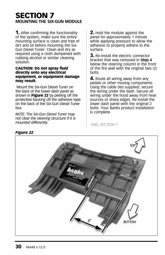
1. After confirming the functionality of the system, make sure the entire mounting surface is clean and free of dirt and oil before mounting the Six-Gun Diesel Tuner. clean and dry as required using a cloth dampened with rubbing alcohol or similar cleaning solution.
CAUTION: Do not spray fluid directly onto any electrical equipment, or equipment damage may result.
Mount the Six-Gun Diesel Tuner on the back of the lower dash panel as shown in Figure 22 by peeling off the protective backing off the adhesive tape on the back of the Six-Gun Diesel Tuner box.
Note: the Six-Gun Diesel tuner may not clear the steering structure if it is mounted differently.
2. Hold the module against the panel for approximately 1 minute while applying pressure to allow the adhesive to properly adhere to the surface.
3. Re-install the electric connector bracket that was removed in Step 4 below the steering column in the front of the fire wall with the original two (2) bolts.
4. Route all wiring away from any pedals or other moving components. Using the cable ties supplied, secure the wiring under the dash. Secure all wiring under the hood away from heat sources or sharp edges. Re-install the lower dash panel with the original 2 bolts. Your Banks product installation is complete.
-END, SEcTION 7-
SECTION 7MOUNTING THE SIx-GUN MODULE
Figure 22
96448 v.12.0 31
SECTION 8TROUBLESHOOTING
Note: the Six-Gun Diesel tuner requires the engine coolant temperature (eCt) to be above 125º before it will add fuel.
If you feel that your Six-Gun Diesel Tuner is not functioning properly, some diagnostics can be performed. Your Six-Gun Diesel Tuner is equipped with diagnostic features that will detect and display certain errors. Remove the Six-Gun Diesel Tuner from its mounting location while keeping all connectors plugged in. Turn vehicle key to ON position. Observe the two LEDs mounted on the upper corners of the black connector on the end of the Six-Gun Diesel Tuner. If all wire connections are correct, a steady green light is illuminated. If the green light is not illuminated when key is on, check power supply hookup and the fuse on the Six-Gun main wire harness. If connection and fuse are okay, contact Banks Technical Service.
If a connection is incorrect or if there is a problem with the system, when the key is on the red LED will flash in sequence to identify a diagnostic code. A Six-Gun Diesel Tuner’s diagnostic code is comprised of 2 digits. Each code is expressed in a sequence of 2 sets of the flashing red LED separated by a brief flashing of the green LED in between. Each set of a number of red LED flashes represents a digit. A longer flashing of the green LED separates the sequences. The LEDs will continue to flash to display all the errors, and then repeat. Table 1 lists some common diagnostic codes.
For example, if a faulty thermocouple is detected (code “2,3”) by the Six-Gun Diesel Tuner, the following red and green LED flashing sequence is observed when the key is on:
(1) Two times flashing RED LED
(2) One time quick flashing GREEN LED
(3) Three times flashing RED LED
(4) One time longer flashing GREEN LED
The above flashing sequence will repeat continuously. When the problem is corrected, the diagnostic code will be eliminated and replaced by a steady green light.
Note: If multiple codes are set, they will be displayed in a series separated by the longer flashing green LeD. When reading codes, make sure to watch the entire series until you see the first code repeat.
Note: the “4,3” code comes on when the Six-Gun Diesel tuner module is first installed on a vehicle. to eliminate this code, follow the instructions described in the “LeARNING tRANSMISSIoN” section.
If problem persists, contact Banks Technical Service.
If the Six-Gun Diesel Tuner should ever need to be removed from the vehicle, the system includes a by-pass plug that must be connected to the white 8-pin connector (next to the 10-pin connector) on the Banks wire harness. Failure to utilize the by-pass plug will result in a “check Engine” light on the dash and a Diagnostic Trouble code being stored in the factory computer and the engine will not start.
-END, SEcTION 8-
32 96448 v.12.0
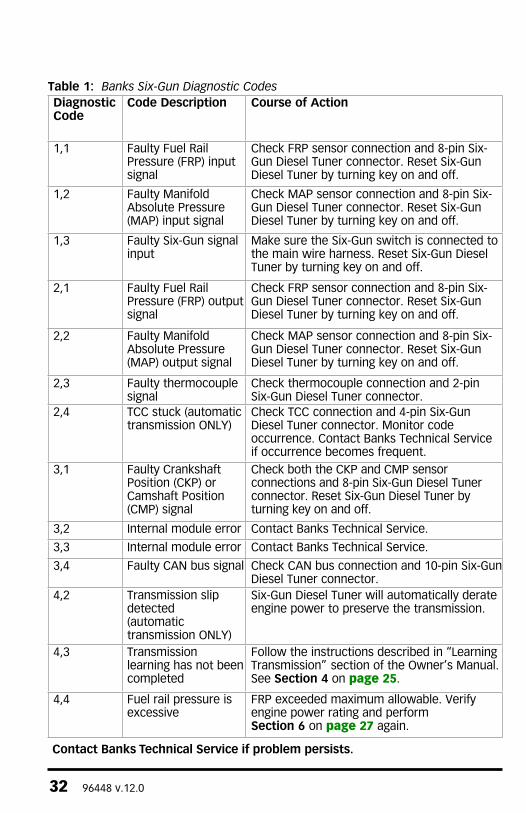
Table 1: Banks Six-Gun Diagnostic CodesDiagnostic Code
Code Description Course of action
1,1 Faulty Fuel Rail Pressure (FRP) input signal
Check FRP sensor connection and 8-pin Six- Gun Diesel Tuner connector. Reset Six-Gun Diesel Tuner by turning key on and off.
1,2 Faulty Manifold Absolute Pressure (MAP) input signal
Check MAP sensor connection and 8-pin Six-Gun Diesel Tuner connector. Reset Six-Gun Diesel Tuner by turning key on and off.
1,3 Faulty Six-Gun signal input
Make sure the Six-Gun switch is connected to the main wire harness. Reset Six-Gun Diesel Tuner by turning key on and off.
2,1 Faulty Fuel Rail Pressure (FRP) output signal
Check FRP sensor connection and 8-pin Six-Gun Diesel Tuner connector. Reset Six-Gun Diesel Tuner by turning key on and off.
2,2 Faulty Manifold Absolute Pressure (MAP) output signal
Check MAP sensor connection and 8-pin Six-Gun Diesel Tuner connector. Reset Six-Gun Diesel Tuner by turning key on and off.
2,3 Faulty thermocouple signal
check thermocouple connection and 2-pin Six-Gun Diesel Tuner connector.
2,4 Tcc stuck (automatic transmission ONLY)
Check TCC connection and 4-pin Six-Gun Diesel Tuner connector. Monitor code occurrence. contact Banks Technical Service if occurrence becomes frequent.
3,1 Faulty crankshaft Position (cKP) or camshaft Position (cMP) signal
check both the cKP and cMP sensor connections and 8-pin Six-Gun Diesel Tuner connector. Reset Six-Gun Diesel Tuner by turning key on and off.
3,2 Internal module error contact Banks Technical Service.
3,3 Internal module error contact Banks Technical Service.
3,4 Faulty cAN bus signal Check CAN bus connection and 10-pin Six-Gun Diesel Tuner connector.
4,2 Transmission slip detected (automatic transmission ONLY)
Six-Gun Diesel Tuner will automatically derate engine power to preserve the transmission.
4,3 Transmission learning has not been completed
Follow the instructions described in “Learning Transmission” section of the Owner’s Manual. See Section 4 on page 25.
4,4 Fuel rail pressure is excessive
FRP exceeded maximum allowable. Verify engine power rating and perform Section 6 on page 27 again.
Contact Banks Technical Service if problem persists.
96448 v.12.0 33
Note: this procedure should only be performed if:
(a) A ”4,2” code for transmission slip detection is repeatedly set or will not clear and the transmission is not actually slipping; or
(b) The Six-Gun Diesel Tuner is moved to a new vehicle; or
(c) The speedometer has been recalibrated for different gearing or tire size; or
(d) Instructed to do so by Banks Technical Staff.
Your Six-Gun Diesel Tuner also has the capability to clear the information related to the learned transmission type and gear ratios. The diagnostic code “4,3” will reappear after the procedures are carried out correctly. Follow the steps below to unlearn the transmission on your Six-Gun Diesel Tuner.
CAUTION: The following procedures can only be carried out with the engine off.
B1. Turn the vehicle key to the ON position but DO NOT start engine.
B2. Fully depress the throttle pedal and then release it completely. Repeat for 5 times. The green LED will flash when this is completed successfully.
B3. Turn key off. Wait 10 seconds or until the green LED goes off and stays off. Turn key to on position but do not start engine.
B4. Fully depress the throttle pedal and then release it completely. Repeat for 5 times. The “4,3” diagnostic code will display when this is completed successfully.
Note: When the transmission type and gear ratios are cleared (with code “4,3” displayed), the engine power returns and remains in stock level until the Six-Gun Diesel tuner re-learns the transmission and code “4,3” is eliminated. Follow the procedures in Section 4’s LeARNING tRANSMISSIoN to eliminate code “4,3”.
-END, SEcTION 9-
SECTION 9CLEaRING LEaRNED TRaNSMISSION PROCEDURE
Figure 17

34 96448 v.12.0
NOTES

96448 v.12.0 35
NOTES

Gale Banks Engineering 546 Duggan Avenue • Azusa, cA 91702 (626) 969-9600 • Fax (626) 334-1743
Product Information & Sales: (888) 635-4565customer Support: (888) 839-5600 Installation Support: (888) 839-2700
bankspower.com