owner’s manual - lawn mower manuals · owner’s manual safety, assembly, ... this manual covers...
TRANSCRIPT

OWNER’S MANUALSafety, Assembly, Operating, and Maintenance Instructions
Model MT (20.0 / 25.0 HP)
(Covers Serial Numbers 95-21329 and on)
Please Read and Save These Instructions Effective Date: 08-14-98For Safety, Read All Safety and Operation P/N 8000-1Instructions Prior to Operating Machine Price $5.00
™

Foreword
Thank you. . .for purchasing a Walker mower. Every effort has been made to provide you with themost reliable mower on the market, and we are sure you will be among our many satisfied custom-ers. If for any reason this product does not perform to your expectations, please contact us at (970)221-5614. Every customer is important to us. Your satisfaction is our goal.
Please. . .read this manual thoroughly! This manual is to be used in conjunction with the enginemanufacturer’s manual for the specific engine on the mower model you have purchased. Before youoperate your new mower, please read this entire manual. Some of the information is crucial for prop-er operation and maintenance of this mower - it will help protect your investment and ensure that themower performs to your satisfaction. Some of the information is important to your safety and mustbe read and understood to help prevent possible injury to the operator or others. If anything in thismanual is confusing or hard to understand, please call our service department, at (970) 221-5614,for clarification before operating or servicing this mower.
This manual covers Model MT with the Kohler Command CH20 (20.0 HP) gasoline engine, or op-tional Kohler Command CH25 (25.0 HP) gasoline engine.
All shields and guards must be in place for the proper and safe operation of this machine.Where they are shown removed in this manual, it is for illustration purposes only. Do not operatethis machine unless all shields and guards are in place.
Specifications given are based on the latest information available at the time this manual was pro-duced.
Walker Mfg. Co. is continually striving to improve the design and performance of its products. Wereserve the right to make changes in specifications and design without thereby incurring any obli-gation relative to previously manufactured products.
Sincerely, WALKER MANUFACTURING COMPANY
Bob Walker, President

Table of Contents
General Information ________________ 1 HIGHLIGHTED INFORMATION _____________ 1 GLOSSARY ____________________________ 1 IDENTIFYING NUMBER LOCATIONS________ 1 ENGINE SERIAL NUMBER LOCATION ______ 2 SERVICING OF ENGINEAND DRIVETRAIN COMPONENTS__________ 2
Specifications _______________________ 3
ENGINE________________________________ 3ELECTRICAL SYSTEM ___________________ 3TRANSMISSION_________________________ 3BLADE DRIVE __________________________ 4 TIRE SIZE ______________________________ 4 TIRE PRESSURE ________________________ 5 DIMENSIONS (Tractor and Mower) _________ 5MOWER DECK __________________________ 5CURB WEIGHT__________________________ 5DRIVE BELTS___________________________ 6 GHS SYSTEM (Optional)__________________ 6 SEAT __________________________________ 6 FRAME/BODY CONSTRUCTION ___________ 6
Component Identification___________ 7
Safety Instructions _________________ 10
BEFORE OPERATING ___________________ 10 OPERATING ___________________________ 11 MAINTENANCE ________________________ 12 SAFETY, CONTROL, AND INSTRUCTION DECALS _____________ 14
Assembly Instructions _____________ 16 SETUP INSTRUCTIONS _________________ 16
Tire Installation (Tractor) _______________ 16 Battery Service_______________________ 16
Wet Battery Service __________________ 16Dry Battery Service___________________ 16 Battery Charging _____________________ 17Battery Installation ___________________ 17
Mower Deck Assembly ________________ 17Deck Caster Wheels Installation _________ 17Deck Discharge Chute Installation _______ 18 Deck Discharge Shield Installation _______ 18PTO Shaft Guard Installation ___________ 18
Mower Deck Installation on Tractor ______ 18 Deck Installation _____________________ 18Deck Leveling _______________________ 20
PREOPERATING CHECKLIST ____________ 21
Operating Instructions_____________ 24
CONTROL IDENTIFICATION, LOCATION, AND FUNCTION _____________ 24
Operating Controls ___________________ 24 Engine Choke_______________________ 24 Engine Throttle ______________________ 25 Forward Speed Control (FSC) __________ 25 Steering Levers _____________________ 25 Blade Clutch (PTO) __________________ 25 Parking Brake_______________________ 25Front Body Latch Release _____________ 26Transmission Lockout Levers___________ 26Cold Start Lever (Jackshaft Drive Belt Release)_ 26
Instrument Panel _____________________ 28 Hourmeter _________________________ 29 Voltmeter __________________________ 29 Oil Pressure Warning Light ____________ 29 Over Temperature Warning Light ________ 29 Ignition Switch ______________________ 29 Light Switch (For Optional Lights) _______ 29 Warning Horn _______________________ 29
STARTING THE ENGINE_________________ 30 ADJUSTING GROUND SPEED AND STEERING _________________ 31 ENGAGING THE MOWER________________ 32STOPPING THE MACHINE _______________ 33 ADJUSTING CUTTING HEIGHT ___________ 34 TRANSMISSION LOCKOUT ______________ 34 RECOMMENDATIONS FOR MOWING ______ 35RECOMMENDATIONS FOR TILT-UP DECKOPERATION/TRANSPORT _______________ 36GRASS HANDLING SYSTEM (GHS) _______ 37
General Information __________________ 38 Clogging Checklist ___________________ 39 Using the Tilt-Up Deck ________________ 40Using the GHS Catcher ________________ 40
Powerfil ® __________________________ 40 “Full” Signal Horn ____________________ 40
Cleaning the GHS Exhaust Screen ______ 40 Dumping the Catcher _________________ 41
Tailgate Dumping ____________________ 41 Using the Dump Bag _________________ 41 Power Dump Option __________________ 42

Table of Contents
Maintenance Instructions __________ 44
MAINTENANCE SCHEDULE CHART _______ 44IMPORTANT TIPS FOR CARE OF THE KOHLER ENGINE _____ 45
Fuel System _________________________ 45 Starting/Stopping _____________________ 45 Cooling System ______________________ 45 Air Cleaner System ___________________ 45 Oil _________________________________ 45
LUBRICATION _________________________ 46 Engine Oil ___________________________ 46
Engine Break-In Oil___________________ 46Checking Engine Crankcase Oil Level ____ 46 Changing Engine Crankcase Oil/Oil Filter _ 46
Grease Fitting and Oil Point Lubrication __ 47Mower Deck Gearbox Lubrication _______ 50DSD52 or DSD62 Mower Deck Lubrication 50Tractor PTO Gearbox Lubrication _______ 51
Checking Gearbox Oil Level ____________ 51 Changing Gearbox Oil ________________ 51
Gear Axle Lubrication _________________ 51 Hydrostatic Transmission Fluid _________ 52
Checking HydrostaticTransmission Fluid Level ______________ 52Changing Hydrostatic Transmission Fluid__ 52
CLEANING ____________________________ 53 Engine Air Cleaner System _____________ 53
Turbine Precleaner ___________________ 54 Donaldson Radialseal™Air Cleaner (Primary) _________________ 54Kohler Air Cleaner (Secondary) _________ 56
Foam Precleaner __________________ 56Paper Element ____________________ 56
Engine Cooling System________________ 57 Air Intake System ____________________ 57Cylinder Head Cooling Fins ____________ 57
Grass Buildup in Mower Housing________ 58 Non-Tilting Decks ____________________ 58Tilt-Up Decks _______________________ 58
GHS Blower _________________________ 59GHS Exhaust Screen __________________ 59Hydrostatic Transmission Cooling Fins __ 60
CHECKING/SERVICING _________________ 60 Security of Air Filtration Components ____ 60 Battery______________________________ 60
Electrolyte Level _____________________ 60 Cleaning the Terminals ________________ 61Charging the Battery __________________ 61
Tire Pressure ________________________ 61Sharpen Mower Blades ________________ 61Drive Belts __________________________ 62Mower Deck Gearbox Oil Seals _________ 63Spark Plugs _________________________ 63
Fuel Lines and Clamps ________________ 63Engine Starter _______________________ 63Blade Brake Action ___________________ 63
REPLACING/REPAIRING ________________ 63 Drive Belts __________________________ 63
Engine PTO Drive Belt ________________ 65 Jackshaft Drive Belt __________________ 66 GHS Blower Drive Belt ________________ 67 Hydrostatic Ground Drive Belt __________ 68
Fuel Filter ___________________________ 69 Blade Overload Shear Bolts ____________ 69 Mower Blades _______________________ 70 Mower Deck Gearbox Replacement______ 70 GHS Blower Assembly ________________ 71
GHS Blower Assembly Removal ________ 71Blower Wheel Removal _______________ 72 Blower Wheel Installation ______________ 72GHS Blower Assembly Installation _______ 72
ADJUSTMENTS________________________ 73 Safety Switches ______________________ 73
Seat Switch ________________________ 73FSC Neutral-Park Switch ______________ 73PTO Switch_________________________ 73
Tail Wheel Bearing Preload_____________ 73 Blade Clutch (PTO) ___________________ 74
Clutch Engagement/Belt Tension ________ 74 Clutch Disengagement/Brake Action _____ 75Stop Block Eccentric Adjustment ________ 76Clutch Idler Pulley Travel Adjustment_____ 76Blade Brake Band Adjustment __________ 76
Transmission Control _________________ 77 Set Forward Travel Limit (Stop) _________ 77 Steering Lever End Play Adjustment _____ 78 Neutral Function Adjustment ___________ 78 Straight Ground Travel Adjustment ______ 79
Forward Speed Control Friction Lock ____ 79Tilt-Up Deck Adjustable Stop ___________ 80Carburetor __________________________ 80
Engine Idle Adjustment _______________ 80 GHS “Full” Signal Horn with Grass-Pak ® Switch _______________ 81
Troubleshooting (When Horn Fails to Operate) __________ 81 Adjustment (When Horn Sounds at the Wrong Time) __ 82
ELECTRICAL SYSTEM __________________ 82Circuit Breakers______________________ 82Wiring Diagram ______________________ 83
Operator’s Notes___________________ 84
Warranty ___________________________ 87
General Information
1
HIGHLIGHTED INFORMATION
Walker Manufacturing recommends that any ser-vice requiring special training or tools be performedby an authorized Walker Mower Dealer. There areseveral general practices to be aware of in the areaof safety. Most accidents associated with the oper-ation or maintenance of a Walker Mower arecaused by disregarding basic safety precautions orspecific warnings. Such accidents, in most cases,can be prevented by being aware of the dangerspresent.
Information of special importance has been high-lighted in bold type in this manual. Refer to SafetyInstructions for the meanings of DANGER, WARN-ING, CAUTION, IMPORTANT, and NOTE.
GLOSSARY
There are many terms that are either unique to thisequipment or that are used as acronyms. The fol-lowing terms and their definitions will help whileusing this manual:
• DECK is the mowing attachment mounted onthe front of the tractor which includes the carrierframe, deck housing, blade drive gearboxes,and cutter blades.
• FORWARD SPEED CONTROL (FSC) con-trols the maximum forward speed of the trac-tor; functioning as a cruise control.
• GRASS HANDLING SYSTEM (GHS) collectsmowed material and deposits it in the catcher.
• GRASS-PAK SWITCH is mounted on thegrass delivery spout (in the catcher) and acti-vates the “full” signal horn when the grasscatcher is full.
• GROUND DRIVE refers to the dual hydrostatictransmissions which drive the main wheels.
• HYDROSTATIC TRANSMISSION transmitsand controls power from the ground drive belt tothe main drive wheel.
• LEFT HAND (LH) refers to the left-hand side ofthe tractor when the operator is seated facingforward in the tractor seat.
• POWER TAKE-OFF (PTO) transmits enginepower to run the cutter blades and GHS blower.
• POWERFIL spreads the mowed materialthroughout the interior of the grass catcher byan oscillating delivery spout.
• RIGHT HAND (RH) refers to the right-hand sideof the tractor when the operator is seated facingforward in the tractor seat.
• SIDE DISCHARGE (SD) mows but does notcollect the mowed material.
• STEERING LEVERS steer the tractor by con-trolling the dual hydrostatic transmissions.
• TRACTOR is the prime mover, including the en-gine, drive train, operator seat, and controls tooperate the mower.
• TRANSMISSION LOCKOUT releases the hy-drostatic transmissions to permit freewheelingthe tractor.
IDENTIFYING NUMBER LOCATIONS
The tractor serial number plate is affixed to the trac-tor body just below the left rear corner of the seat.The mower deck serial number plate is affixedalongside the angle iron framing on the RH side ofthe RH mower blade drive. Model and serial num-bers are helpful when obtaining replacement partsand maintenance assistance. For ready reference,please record these numbers in the space provided.
Fill In By Purchaser
Tractor Model No. _______________________
Tractor Serial No. _______________________
Deck Serial No. _______________________
Engine Model No. _______________________
Engine Serial No. _______________________
Date of Purchase _______________________

General Information
2
Tractor Serial Number Location
Mower Deck Serial Number Location
ENGINE SERIAL NUMBER LOCATION
Refer to the engine manual that accompanies thismanual for the location of the engine serial number.For the mower model covered by this manual, an en-gine manual is available covering the Kohler CH20and CH25 gasoline engines.
Engine Serial Number Location
SERVICING OF ENGINE AND DRIVETRAINCOMPONENTS
The detailed servicing and repair of the engine,hydrostatic transmission, and gearboxes are not cov-ered in this manual. Only routine maintenance andgeneral service instructions are provided. For theservice of these components during the limited war-ranty period, it is important to find a local, authorizedservicing agent of the component manufacturer.Any unauthorized work done on these compo-nents during the warranty period may void the war-ranty. If you have any difficulty finding an authorizedoutlet or obtaining warranty service, please contactour Service Department for assistance:
Walker Manufacturing Company5925 E. Harmony RoadFort Collins, CO 80528
1-970-221-5614
Service manuals are available for each of thesecomponents from their respective manufacturers asfollows:
Kohler Engines Kohler CompanyKohler, WI 53044
Hydrostatic Eaton CorporationTransmissions 15151 Highway 5
Eden Prairie, MN 55344
Gearboxes (Deck) Tecumseh Products Co.900 North StreetGrafton, Wl 53024
Serial Number
Serial Number
Serial Number

Specifications
3
MODEL MT 20.0 HP MT 25.0 HP
ENGINE
Manufacturer/Model Kohler CH20, 2 Cyl.,Gasoline (Air Cooled)
Kohler CH25, 2 Cyl.,Gasoline (Air Cooled)
Displacement 38.1 cu. in. (624 cc) 44.0 cu. in. (725 cc)
HP (@ 3600 RPM) 20.0 25.0
Max. RPM (No Load) 3750 3750
Governed RPM 3600 3600
Max. Torque [ft-lb (N⋅m) @ RPM] 32 (43.4) @ 2500 39.5 (53.6) @ 2400
Idle RPM 1200 ± 75 1200 ± 75
Spark Plug Type Champion RC12YC Champion RC12YC
Spark Plug Gap .030 in. (.76 mm) .030 in. (.76 mm)
Crankcase Capacity 2.1 qts (2.0 liters) 2.1 qts (2.0 liters)
Crankcase Lubricant API SF, SG, or SH Grade Oil Only with 10W-30 Viscosity above 0° F (-18° C), or 5W-20 or 5W-30 Viscosity below 32° F (0° C)
API SF, SG, or SH Grade Oil Only with 10W-30 Viscosity above 0° F (-18° C), or 5W-20 or 5W-30 Viscosity below 32° F (0° C)
Fuel Tank Capacity 4.3 Gallons (16.3 liters) 4.3 Gallons (16.3 liters)
Fuel Regular Grade UnleadedGasoline (87 Octane)
Regular Grade UnleadedGasoline (87 Octane)
Cooling System Capacity Air Cooled Air Cooled
ELECTRICAL SYSTEM
Battery 12 Volt, 35AH, 295 CCA 12 Volt, 35AH, 295 CCA
Charging System Flywheel Alternator Flywheel Alternator
Charging Output 15 Amp DC (Regulated) 15 Amp DC (Regulated)
System Polarity Negative Ground Negative Ground
Ignition Electronic Capacitive Discharge
Electronic Capacitive Discharge
Starter 12 Volt Electric Ring-Gear Type, Solenoid Shift
12 Volt Electric Ring-Gear Type, Solenoid Shift
Interlock Switch Ignition Lockout by Seat Switch, Transmission Neutral and Blade Clutch
Ignition Lockout by Seat Switch, Transmission Neutral and Blade Clutch
Circuit Breaker Manual Reset (30A) Manual Reset (30A)
TRANSMISSION
Manufacturer/Model Dual Hydrostatic, EatonModel 7, Each WheelIndependently Driven
Dual Hydrostatic, EatonModel 7, Each WheelIndependently Driven
Steering Hand Lever Control /Individual Wheel
Hand Lever Control /Individual Wheel
Forward Speed Control Precision Friction Lock Lever,Cruise Control, withNeutral-Park Position
Precision Friction Lock Lever,Cruise Control, withNeutral-Park Position
Specifications
4
MODEL MT 20.0 HP MT 25.0 HP
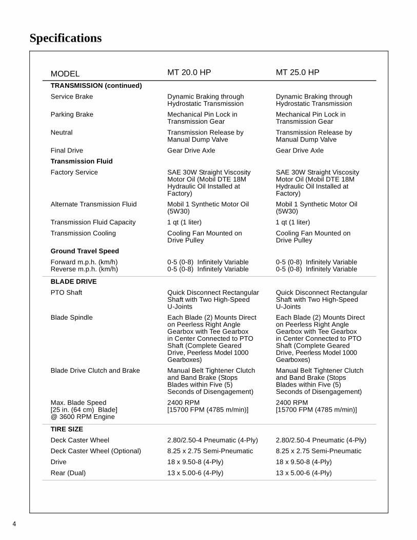
TRANSMISSION (continued)
Service Brake Dynamic Braking throughHydrostatic Transmission
Dynamic Braking throughHydrostatic Transmission
Parking Brake Mechanical Pin Lock inTransmission Gear
Mechanical Pin Lock inTransmission Gear
Neutral Transmission Release byManual Dump Valve
Transmission Release byManual Dump Valve
Final Drive Gear Drive Axle Gear Drive Axle
Transmission Fluid
Factory Service SAE 30W Straight ViscosityMotor Oil (Mobil DTE 18MHydraulic Oil Installed at Factory)
SAE 30W Straight ViscosityMotor Oil (Mobil DTE 18MHydraulic Oil Installed at Factory)
Alternate Transmission Fluid Mobil 1 Synthetic Motor Oil(5W30)
Mobil 1 Synthetic Motor Oil(5W30)
Transmission Fluid Capacity 1 qt (1 liter) 1 qt (1 liter)
Transmission Cooling Cooling Fan Mounted onDrive Pulley
Cooling Fan Mounted onDrive Pulley
Ground Travel Speed
Forward m.p.h. (km/h)Reverse m.p.h. (km/h)
0-5 (0-8) Infinitely Variable 0-5 (0-8) Infinitely Variable
0-5 (0-8) Infinitely Variable 0-5 (0-8) Infinitely Variable
BLADE DRIVE
PTO Shaft Quick Disconnect RectangularShaft with Two High-SpeedU-Joints
Quick Disconnect RectangularShaft with Two High-SpeedU-Joints
Blade Spindle Each Blade (2) Mounts Directon Peerless Right AngleGearbox with Tee Gearboxin Center Connected to PTOShaft (Complete Geared Drive, Peerless Model 1000 Gearboxes)
Each Blade (2) Mounts Directon Peerless Right AngleGearbox with Tee Gearboxin Center Connected to PTOShaft (Complete Geared Drive, Peerless Model 1000 Gearboxes)
Blade Drive Clutch and Brake Manual Belt Tightener Clutchand Band Brake (Stops Blades within Five (5) Seconds of Disengagement)
Manual Belt Tightener Clutchand Band Brake (Stops Blades within Five (5) Seconds of Disengagement)
Max. Blade Speed[25 in. (64 cm) Blade]@ 3600 RPM Engine
2400 RPM[15700 FPM (4785 m/min)]
2400 RPM[15700 FPM (4785 m/min)]
TIRE SIZE
Deck Caster Wheel 2.80/2.50-4 Pneumatic (4-Ply) 2.80/2.50-4 Pneumatic (4-Ply)
Deck Caster Wheel (Optional) 8.25 x 2.75 Semi-Pneumatic 8.25 x 2.75 Semi-Pneumatic
Drive 18 x 9.50-8 (4-Ply) 18 x 9.50-8 (4-Ply)
Rear (Dual) 13 x 5.00-6 (4-Ply) 13 x 5.00-6 (4-Ply)
Specifications
5
MODEL MT 20.0 HP MT 25.0 HP
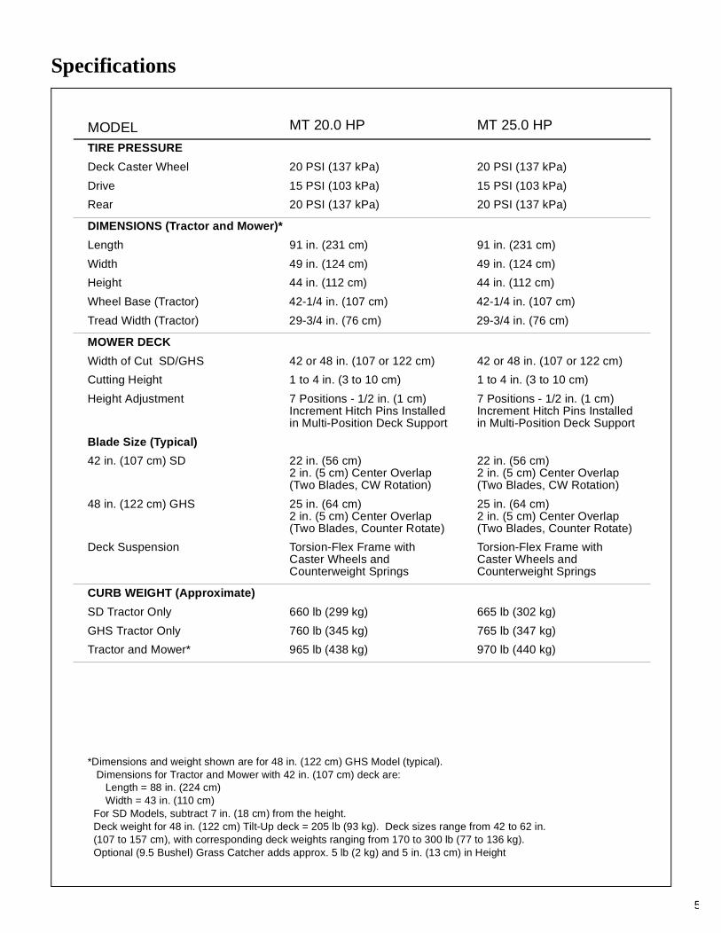
TIRE PRESSURE
Deck Caster Wheel 20 PSI (137 kPa) 20 PSI (137 kPa)
Drive 15 PSI (103 kPa) 15 PSI (103 kPa)
Rear 20 PSI (137 kPa) 20 PSI (137 kPa)
DIMENSIONS (Tractor and Mower)*
Length 91 in. (231 cm) 91 in. (231 cm)
Width 49 in. (124 cm) 49 in. (124 cm)
Height 44 in. (112 cm) 44 in. (112 cm)
Wheel Base (Tractor) 42-1/4 in. (107 cm) 42-1/4 in. (107 cm)
Tread Width (Tractor) 29-3/4 in. (76 cm) 29-3/4 in. (76 cm)
MOWER DECK
Width of Cut SD/GHS 42 or 48 in. (107 or 122 cm) 42 or 48 in. (107 or 122 cm)
Cutting Height 1 to 4 in. (3 to 10 cm) 1 to 4 in. (3 to 10 cm)
Height Adjustment 7 Positions - 1/2 in. (1 cm)Increment Hitch Pins Installedin Multi-Position Deck Support
7 Positions - 1/2 in. (1 cm)Increment Hitch Pins Installedin Multi-Position Deck Support
Blade Size (Typical)
42 in. (107 cm) SD 22 in. (56 cm) 2 in. (5 cm) Center Overlap(Two Blades, CW Rotation)
22 in. (56 cm) 2 in. (5 cm) Center Overlap(Two Blades, CW Rotation)
48 in. (122 cm) GHS 25 in. (64 cm)2 in. (5 cm) Center Overlap(Two Blades, Counter Rotate)
25 in. (64 cm)2 in. (5 cm) Center Overlap(Two Blades, Counter Rotate)
Deck Suspension Torsion-Flex Frame withCaster Wheels andCounterweight Springs
Torsion-Flex Frame withCaster Wheels andCounterweight Springs
CURB WEIGHT (Approximate)
SD Tractor Only 660 lb (299 kg) 665 lb (302 kg)
GHS Tractor Only 760 lb (345 kg) 765 lb (347 kg)
Tractor and Mower* 965 lb (438 kg) 970 lb (440 kg)
*Dimensions and weight shown are for 48 in. (122 cm) GHS Model (typical). Dimensions for Tractor and Mower with 42 in. (107 cm) deck are:
Length = 88 in. (224 cm)Width = 43 in. (110 cm)
For SD Models, subtract 7 in. (18 cm) from the height.Deck weight for 48 in. (122 cm) Tilt-Up deck = 205 lb (93 kg). Deck sizes range from 42 to 62 in. (107 to 157 cm), with corresponding deck weights ranging from 170 to 300 lb (77 to 136 kg).Optional (9.5 Bushel) Grass Catcher adds approx. 5 lb (2 kg) and 5 in. (13 cm) in Height

Specifications
6
MODEL MT 20.0 HP MT 25.0 HP
DRIVE BELTS
Engine PTO Walker P/N 8230 Walker P/N 8230
Jackshaft Drive Gates 3VX355(or Walker P/N 6231)
Gates 3VX355(or Walker P/N 6231)
Ground Drive, Micro-V Walker P/N 7248 Walker P/N 7248
Blower (GHS Model) Gates 3VX280(or Walker P/N 7234)
Gates 3VX280(or Walker P/N 7234)
GHS SYSTEM (Optional)
Blower 4 x 10 x 1/4 in. (10 x 25 x 1 cm) Three-Blade Paddle Wheel (Driven by Mower Engine)
4 x 10 x 1/4 in. (10 x 25 x 1 cm) Three-Blade Paddle Wheel (Driven by Mower Engine)
Blower Brake Band Brake (Works in Combi-nation with PTO Clutch, Stops Blower within Five (5) Seconds of PTO Disengagement)
Band Brake (Works in Combi-nation with PTO Clutch, Stops Blower within Five (5) Seconds of PTO Disengagement)
Max. Blower Speed 3600 RPM 3600 RPM
Grass Catcher Capacity 65 Gallons (246 liters)/7.0 Bushels
65 Gallons (246 liters)/7.0 Bushels
Optional Grass CatcherCapacity
76 Gallons (335 liters)/9.5 Bushels
76 Gallons (335 liters)/9.5 Bushels
Full Signal Oscillating Vane SwitchMounted on Grass DeliverySpout Triggers Horn Signal
Oscillating Vane SwitchMounted on Grass DeliverySpout Triggers Horn Signal
Powerfil ® Oscillating Delivery SpoutDriven by 12 Volt ElectricGearmotor Spreads Materialthroughout Interior of Catcher@ 25 Cycles/Minute
Oscillating Delivery SpoutDriven by 12 Volt ElectricGearmotor Spreads Materialthroughout Interior of Catcher@ 25 Cycles/Minute
SEAT Contour-Molded, with NylonBacked Vinyl Cover andIntegral Foam Cushion
Contour-Molded, with NylonBacked Vinyl Cover andIntegral Foam Cushion
FRAME/BODY CONSTRUCTION
Frame All Welded Unitized SteelChassis
All Welded Unitized SteelChassis
Body 14 Gauge Steel 14 Gauge Steel
Deck 11 Gauge Steel 11 Gauge Steel
GHS Catcher and Chutes Molded Cross-LinkedPolyethylene (UV Stabilized)
Molded Cross-LinkedPolyethylene (UV Stabilized)
NOTE: The manufacturer reserves the right to make changes in specifications shown herein at any time without notice or obligation.

Component Identification
7
Front View and Right Side View
NOTE: Control Identificationshown in OperatingInstructions section.
Grass Handling System7.0 Bushel Catcher
Anti-ScuffRoller
Transmission Control RodAdjustment Nut (RH)
Deck Support Arms
Transmission Control RodAdjustment Nut (LH)
Deck Lift Handle(Cutting Height Adjustment)
DeckCaster Wheels
Tilt-Up HookTilt-Up
Deck Handle
Catcher Lift /Dump Handle
Deck Support Pinsand Height Adjustment
Hitch Pins
Catcher DoorSafety Latch
TurbinePrecleaner
Tilt-UpLatch Spring Clip
Footrests
Counterweight Spring and Protective Cover
Fuel Tankand Cap
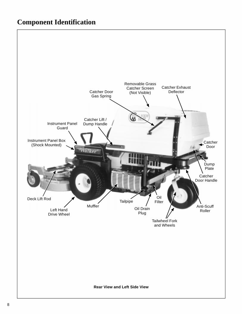
Component Identification
8
Catcher DoorGas Spring
Instrument PanelGuard
Instrument Panel Box(Shock Mounted)
Deck Lift Rod
Left HandDrive Wheel
MufflerTailpipe
Oil DrainPlug
CatcherDoor Handle
DumpPlate
CatcherDoor
Anti-ScuffRoller
OilFilter
Tailwheel Forkand Wheels
Removable GrassCatcher Screen
(Not Visible)Catcher Exhaust
Deflector
Catcher Lift /Dump Handle
Rear View and Left Side View
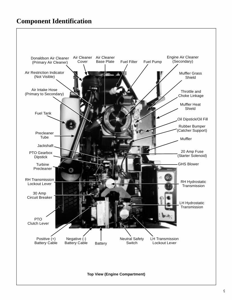
Component Identification
9
Air Restriction Indicator(Not Visible)
Air Intake Hose(Primary to Secondary)
Air CleanerBase Plate Fuel Pump
Engine Air Cleaner(Secondary)
Muffler GrassShield
Throttle and Choke Linkage
Muffler HeatShield
Oil Dipstick/Oil Fill
Rubber Bumper(Catcher Support)
Muffler
20 Amp Fuse(Starter Solenoid)
GHS Blower
RH HydrostaticTransmission
PTO Clutch Lever
30 AmpCircuit Breaker
RH TransmissionLockout Lever
TurbinePrecleaner
PTO GearboxDipstick
Jackshaft
Positive (+)Battery Cable
Negative (-)Battery Cable Battery
Donaldson Air Cleaner(Primary Air Cleaner)
Neutral SafetySwitch
LH TransmissionLockout Lever
LH HydrostaticTransmission
PrecleanerTube
Fuel Tank
Air CleanerCover Fuel Filter
Top View (Engine Compartment)
Safety Instructions
10
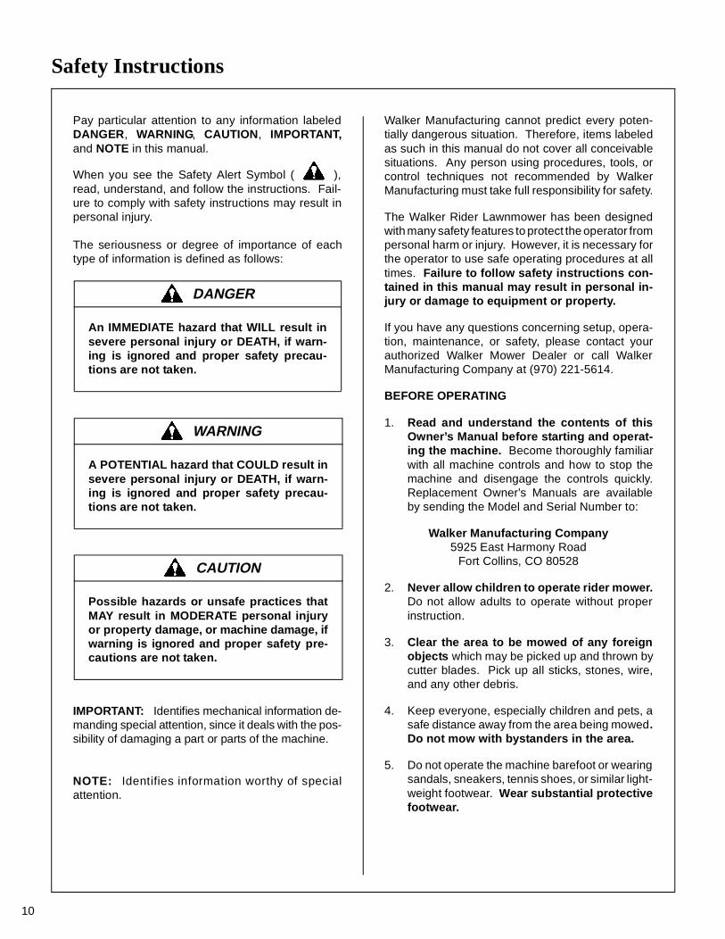
Pay particular attention to any information labeledDANGER, WARNING, CAUTION, IMPORTANT,and NOTE in this manual.
When you see the Safety Alert Symbol ( ),read, understand, and follow the instructions. Fail-ure to comply with safety instructions may result inpersonal injury.
The seriousness or degree of importance of eachtype of information is defined as follows:
IMPORTANT: Identifies mechanical information de-manding special attention, since it deals with the pos-sibility of damaging a part or parts of the machine.
NOTE: Identifies information worthy of specialattention.
Walker Manufacturing cannot predict every poten-tially dangerous situation. Therefore, items labeledas such in this manual do not cover all conceivablesituations. Any person using procedures, tools, orcontrol techniques not recommended by WalkerManufacturing must take full responsibility for safety.
The Walker Rider Lawnmower has been designedwith many safety features to protect the operator frompersonal harm or injury. However, it is necessary forthe operator to use safe operating procedures at alltimes. Failure to follow safety instructions con-tained in this manual may result in personal in-jury or damage to equipment or property.
If you have any questions concerning setup, opera-tion, maintenance, or safety, please contact yourauthorized Walker Mower Dealer or call WalkerManufacturing Company at (970) 221-5614.
BEFORE OPERATING
1. Read and understand the contents of thisOwner’s Manual before starting and operat-ing the machine. Become thoroughly familiarwith all machine controls and how to stop themachine and disengage the controls quickly.Replacement Owner’s Manuals are availableby sending the Model and Serial Number to:
Walker Manufacturing Company5925 East Harmony Road
Fort Collins, CO 80528
2. Never allow children to operate rider mower.Do not allow adults to operate without properinstruction.
3. Clear the area to be mowed of any foreignobjects which may be picked up and thrown bycutter blades. Pick up all sticks, stones, wire,and any other debris.
4. Keep everyone, especially children and pets, asafe distance away from the area being mowed.Do not mow with bystanders in the area.
5. Do not operate the machine barefoot or wearingsandals, sneakers, tennis shoes, or similar light-weight footwear. Wear substantial protectivefootwear.
DANGER
An IMMEDIATE hazard that WILL result insevere personal injury or DEATH, if warn-ing is ignored and proper safety precau-tions are not taken.
WARNING
A POTENTIAL hazard that COULD result insevere personal injury or DEATH, if warn-ing is ignored and proper safety precau-tions are not taken.
CAUTION
Possible hazards or unsafe practices thatMAY result in MODERATE personal injuryor property damage, or machine damage, ifwarning is ignored and proper safety pre-cautions are not taken.
Safety Instructions
11
6. Do not wear loose fitting clothing that could getcaught in moving parts. Do not operate thismachine while wearing shorts; always wearadequate protective clothing, including longpants. Wearing safety glasses, safety shoes,and a helmet is advisable and required by somelocal ordinances and insurance regulations.
7. Prolonged exposure to loud noise can cause im-pairment or loss of hearing. Operator hearingprotection is recommended; particularly forcontinuous operation of the GHS Model due toblower noise level. Wear a suitable hearing pro-tective device, such as earmuffs or earplugs.
8. Keep all protective shields and safety de-vices in place. If a protective shield, safetydevice, or decal is damaged, unusable, or miss-ing, repair or replace it before operating themachine.
9. Be sure interlock switches are functioningcorrectly, so the engine cannot be started un-less the Forward Speed Control lever is in theNEUTRAL-PARK position, and the PTO clutchis in the DISENGAGED position. Also, the en-gine should stop if the operator lifts off the seatwith the PTO clutch in the ENGAGED position.
10. Handle gasoline with care. Gasoline is highlyflammable and its vapors are explosive:
a. Use an approved fuel container.
b. Never add fuel to a running engine or hotengine (allow hot engine to cool severalminutes).
c. Keep matches, cigarettes, cigars, pipes,open flames, or sparks away from the fueltank and fuel container.
d. Always fill the fuel tank outdoors using care.Fill to about one inch from the top of the tank.Use a funnel or spout to prevent spilling.
e. Replace the machine fuel cap and containercap securely and clean up any spilled fuelbefore starting the engine.
11. Never attempt to make any adjustmentswhile the engine is running, except where spe-cifically instructed to do so.
12. The electrical system battery contains sulfuricacid. Avoid any contact with skin, eyes, andclothing. Keep the battery and acid out of reachof children.
OPERATING
1. Operate the mower only in daylight or ingood artificial light with good visibility of the areabeing mowed.
2. Sit on the seat when starting the engine andoperating the machine. Keep feet on the deckfootrests at all times when the tractor is movingand/or mower blades are operating.
3. For a beginning operator, learn to steer (ma-neuver) the tractor with a slow engine speedbefore attempting any mowing operation. Beaware that, with the front mounted mower con-figuration, the back of the tractor swings to theoutside during turns.
4. Remember, for an emergency stop, the forwardmotion of the tractor can always be stopped bypulling the Forward Speed Control (FSC) intothe NEUTRAL-PARK position.
5. Disengage the blade clutch and put the FSC inthe NEUTRAL-PARK position before startingthe engine (an ignition interlock switch normallyprevents starting of the machine if these con-trols are in the OPERATING position).
6. Do not run the engine in a confined area with-out adequate ventilation. Exhaust fumes arehazardous and can be deadly.
7. Do not carry passengers - maximum seatingcapacity is one (1) person.
8. Watch for holes, rocks, and roots in the terrainand for other hidden hazards. When mowing tallgrass, mow higher than desired to expose anyhidden obstacles. Then, clean the area andmow to the desired height.
9. Avoid sudden starts or stops. Before backingthe machine up, look to the rear to be sure noone is behind the machine. Watch carefully fortraffic when crossing or working near roadways.

Safety Instructions
12
10. Disengage the blade drive when transportingthe machine across drives, sidewalks, etc. Ne-ver raise the mower deck while blades arerotating.
11. The maximum recommended side slope op-erating angle is 20 degrees or 33% grade.When operating the machine on a slope, reducespeed and use caution to start, stop, and ma-neuver. To prevent tipping or loss of control ofthe machine, avoid sharp turns or suddenchanges in direction.
12. Never adjust cutting height with the enginerunning. Before adjusting cutting height or ser-vicing, disengage the blade clutch (PTO), stopthe engine, and remove the ignition key. Waitfor all movement to stop before getting off theseat.
NOTE: A blade/blower brake should normallystop drive line rotation within five (5) seconds ofdisengaging the PTO clutch.
13. For side discharge mower decks, do not oper-ate with the grass deflector chute removed.Keep the deflector in the lowest possible posi-tion.
14. For tractors equipped with tilt-up deck, observethe following recommendations:
a. Do not move tractor with deck in tilt-up po-sition.
b. Never tilt body forward with deck in tilt-upposition.
15. For GHS equipped models, do not operate themachine with the grass catcher in the DUMPposition or with the back door OPEN. Dan-gerous projectiles may be thrown out of the dis-charge chute or the back of the grass catcher.
16. For GHS equipped models, use care whenclosing the grass catcher door. Keep fingersand hands away from the hinge and pinchpoints when the door is being closed. Also,keep fingers and hands clear of the door frame.The door is held closed with springs and thedoor may slam shut with considerable force.
17. In case of a clogged or plugged mower deckor GHS catching system:
a. Disengage the blade clutch (PTO) and turnthe engine off before leaving the seat.
b. LOOK to make sure blade drive shaft andblower drive pulley movement has stoppedbefore trying to unclog the system.
c. Disconnect the spark plug wires.
d. Never place hands under the deck or in theGHS blower - use a stick or similar tool toremove clogged material.
18. If the cutting blades strike a solid object or themachine begins to vibrate abnormally, immedi-ately disengage the blade clutch (PTO), stopthe engine, and wait for all moving parts tostop. To prevent accidental starting, discon-nect the spark plug wires. Thoroughly inspectthe mower and repair any damage before re-starting the engine and operating the mower.Make sure cutter blades are in good conditionand blade nuts are torqued to 60 ft-lb (81.3 N⋅m).
19. Do not touch the engine or muffler while theengine is running or immediately after stoppingthe engine. These areas may be hot enough tocause serious burns.
20. When leaving the machine unattended, dis-engage the blade clutch (PTO), stop the en-gine, and remove the key.
MAINTENANCE
1. To prevent accidental starting of the enginewhen servicing or adjusting the machine, re-move the key from the ignition switch and dis-connect the spark plug wires.
2. To reduce fire hazards, keep the engine free ofgrass, leaves, excessive grease, and dirt.
3. Keep all nuts, bolts, and screws tight to ensurethe machine is in a safe, working condition.Check the blade mounting nuts frequently, mak-ing sure they are tight.
Safety Instructions
13
4. Perform only maintenance instructions de-scribed in this manual. Unauthorized main-tenance operations or machine modificationsmay result in unsafe operating conditions.
5. If the engine must be running to perform a main-tenance adjustment, keep hands, feet, andclothing away from moving parts. Do not wearjewelry or loose clothing.
6. Always use the proper engine service man-ual when working on the engine. Unautho-rized maintenance operations or modificationsto the engine may result in unsafe operatingconditions.
7. Altering the equipment or engine in any mannerwhich adversely affects its operation, perfor-mance, durability, or use will VOID the warran-ty and may cause hazardous conditions.
8. Never attempt to disconnect any safety devicesor defeat the purpose of these safety devices.
9. Do not change the engine governor settings oroverspeed the engine. The governor has beenfactory-set for maximum-safe engine operatingspeed.
10. Use genuine factory replacement parts.Substitute parts may result in product malfunc-tion and possible injury to the operator and/orothers.
11. Use care when charging the battery or per-forming maintenance on the battery and electri-cal system:
a. Make sure the battery charger is unpluggedbefore connecting or disconnecting cablesto the battery.
b. Charge the battery in a well-ventilatedspace, so gases produced while chargingcan dissipate. Make sure the battery ventsin the caps are open.
c. Keep sparks, flames, and smoking materi-als away from the battery at all times. Toavoid sparks, use care when removing bat-tery cables from posts.
d. Disconnect both battery cables beforeunplugging any wiring connectors or mak-ing repairs on the electrical system.
IMPORTANT: Keep all applicable manualsimmediately accessible to anyone who mayoperate or service this machine.

Safety Instructions
14
Adjacent to Blower Discharge Chutethrough Body (5804)
SD Deck Discharge Shield (5848)Front Body Adjacent to
RH Steering Lever (7818)
Hydrostat OilReservoir (5810)
On Body Adjacent to ClutchControl Lever (5806)
Right Side of Front Body, BelowFront Body Latch Release (7820)
Rear Cross Member of Front Body (8825)
Rear of Grass Catcher Exhaust Screen (5869)
Engine Shroud (5855)
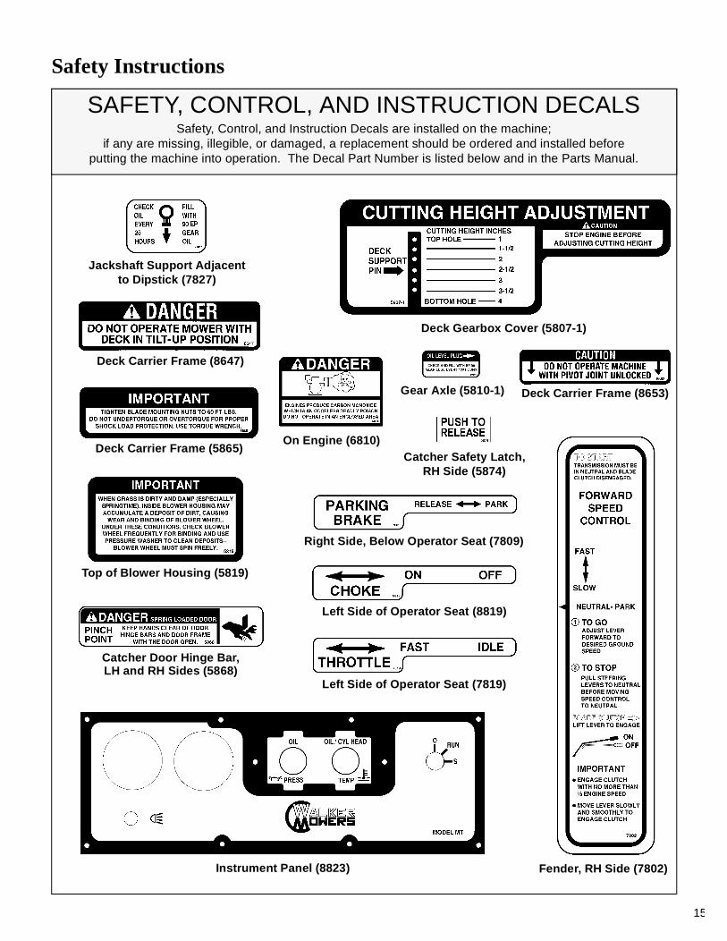
SAFETY, CONTROL, AND INSTRUCTION DECALSSafety, Control, and Instruction Decals are installed on the machine;
if any are missing, illegible, or damaged, a replacement should be ordered and installed beforeputting the machine into operation. The Decal Part Number is listed below and in the Parts Manual.
Each End of Mower Deck (5808)
Safety Instructions
15
Instrument Panel (8823) Fender, RH Side (7802)
Catcher Door Hinge Bar,LH and RH Sides (5868)
Left Side of Operator Seat (7819)
Right Side, Below Operator Seat (7809)
Top of Blower Housing (5819)
Deck Carrier Frame (8653)
Jackshaft Support Adjacentto Dipstick (7827)
Gear Axle (5810-1)
Deck Gearbox Cover (5807-1)
On Engine (6810)
Left Side of Operator Seat (8819)
SAFETY, CONTROL, AND INSTRUCTION DECALSSafety, Control, and Instruction Decals are installed on the machine;
if any are missing, illegible, or damaged, a replacement should be ordered and installed beforeputting the machine into operation. The Decal Part Number is listed below and in the Parts Manual.
Catcher Safety Latch,RH Side (5874)
Deck Carrier Frame (5865)
Deck Carrier Frame (8647)
Assembly Instructions
16
SETUP INSTRUCTIONS
Walker Mowers are shipped partially assembled.After uncrating the tractor and mower deck, initialsetup is required.
NOTE: During the process of unpacking, any dam-aged or missing parts should be noted and reportedto the delivering carrier immediately (put in writingwithin 15 days). The carrier will provide directionsfor proceeding with a claim to receive compensationfor damage.
Tire Installation (Tractor)
• Install the drive tires using the eight (8) lug boltsthat are supplied with the owner’s packet of mater-ials. Drive tires are 18 x 9.50-8, 4-ply; rear tires are13 x 5.00-6, 4-ply.
• Check and adjust the inflation of the tires. Thetire inflation recommendations are:
Drive = 15 PSI (103 kPa)Rear = 20 PSI (137 kPa)
Battery Service
Raise front mower body up for battery access (referto Front Body Latch Release in Operating Instruc-tions). Check the battery for electrolyte level andcharge. The electrolyte level should be at the bot-tom of the vent wells [1/4 to 1/2 in. (6 to 13 mm)above plates]. If the specific gravity is less than1.225, the battery needs charging. If the batteryhas been shipped dry, or is wet but needs service,refer to the following instructions.
Wet Battery Service
If the battery has been shipped wet, but the electro-lyte level is low or the battery needs to be chargedthen:
1. Fill each battery cell with drinking water to thebottom of the vent wells.
2. Charge battery. Refer to Battery Charging inthis section.
Dry Battery Service
To fill (activate) battery with electrolyte (if battery hasbeen shipped dry):
1. Remove the battery hold down bar, disconnectthe battery cables and lift the battery out of thetray.
IMPORTANT: Battery must be removed fromthe mower before filling with electrolyte.
IMPORTANT: Obtain and use only batterygrade sulfuric acid electrolyte with a 1.265 spe-cific gravity to activate the battery. DO NOT usewater or any other liquid during initial activation.
2. Remove the filler caps and carefully fill each celluntil the electrolyte is just above the plates.
DANGER
Activating a battery can be dangerous.The battery should be taken to a reliableservice station, battery store, or powerequipment dealer where a trained techni-cian can activate the battery safely. DONOT attempt to activate the battery unlessyou are experienced in battery servicework. The following activation and charg-ing instructions are provided for use by atrained battery technician.
DANGER
Battery electrolyte is a poisonous and cor-rosive sulfuric acid solution.
• Avoid spillage and contact with skin,eyes, and clothing - causes severe burns.
• To prevent accidents, wear safety gog-gles and rubber gloves when working withelectrolyte.
• Neutralize acid spills with baking sodaand water solution.
Assembly Instructions
17
3. After the battery is filled with electrolyte, replacethe filler caps and charge the battery. Refer toBattery Charging.
Battery Charging
1. Charge the battery at 15 amps for 10 minutes.DO NOT exceed 20 amps maximum recom-mended charging rate. Charge until specificgravity is at least 1.250. Total charging timeshould not exceed one (1) hour.
2. After charging the battery, adjust the electrolytelevel to the bottom of the vent wells [1/4 to 1/2 in.(6 to 13 mm) above the plates].
IMPORTANT: DO NOT overfill the battery.Electrolyte will overflow through the vented capsonto parts of the machine and WILL result insevere corrosion.
3. Install battery.
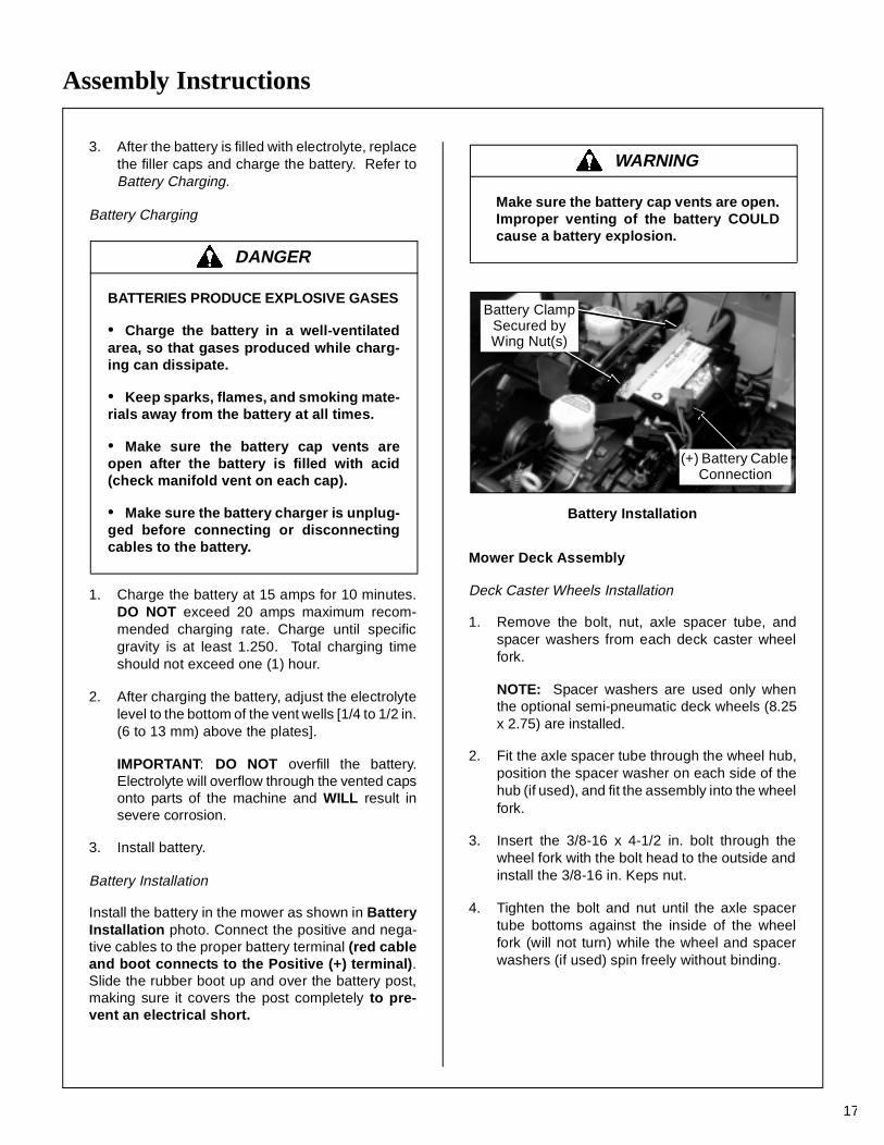
Battery Installation
Install the battery in the mower as shown in BatteryInstallation photo. Connect the positive and nega-tive cables to the proper battery terminal (red cableand boot connects to the Positive (+) terminal).Slide the rubber boot up and over the battery post,making sure it covers the post completely to pre-vent an electrical short.
Battery Installation
Mower Deck Assembly
Deck Caster Wheels Installation
1. Remove the bolt, nut, axle spacer tube, andspacer washers from each deck caster wheelfork.
NOTE: Spacer washers are used only whenthe optional semi-pneumatic deck wheels (8.25x 2.75) are installed.
2. Fit the axle spacer tube through the wheel hub,position the spacer washer on each side of thehub (if used), and fit the assembly into the wheelfork.
3. Insert the 3/8-16 x 4-1/2 in. bolt through thewheel fork with the bolt head to the outside andinstall the 3/8-16 in. Keps nut.
4. Tighten the bolt and nut until the axle spacertube bottoms against the inside of the wheelfork (will not turn) while the wheel and spacerwashers (if used) spin freely without binding.
DANGER
BATTERIES PRODUCE EXPLOSIVE GASES
• Charge the battery in a well-ventilatedarea, so that gases produced while charg-ing can dissipate.
• Keep sparks, flames, and smoking mate-rials away from the battery at all times.
• Make sure the battery cap vents areopen after the battery is filled with acid(check manifold vent on each cap).
• Make sure the battery charger is unplug-ged before connecting or disconnectingcables to the battery.
WARNING
Make sure the battery cap vents are open.Improper venting of the battery COULDcause a battery explosion.
Battery ClampSecured byWing Nut(s)
(+) Battery Cable Connection
Assembly Instructions
18
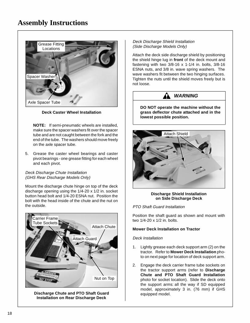
Deck Caster Wheel Installation
NOTE: If semi-pneumatic wheels are installed,make sure the spacer washers fit over the spacertube and are not caught between the fork and theend of the tube. The washers should move freelyon the axle spacer tube.
5. Grease the caster wheel bearings and casterpivot bearings - one grease fitting for each wheeland each pivot.
Deck Discharge Chute Installation(GHS Rear Discharge Models Only)
Mount the discharge chute hinge on top of the deckdischarge opening using the 1/4-20 x 1/2 in. socketbutton head bolt and 1/4-20 ESNA nut. Position thebolt with the head inside of the chute and the nut onthe outside.
Discharge Chute and PTO Shaft GuardInstallation on Rear Discharge Deck
Deck Discharge Shield Installation(Side Discharge Models Only)
Attach the deck side discharge shield by positioningthe shield hinge lug in front of the deck mount andfastening with two 3/8-16 x 1-1/4 in. bolts, 3/8-16ESNA nuts, and 3/8 in. wave spring washers. Thewave washers fit between the two hinging surfaces.Tighten the nuts until the shield moves freely but isnot loose.
Discharge Shield Installationon Side Discharge Deck
PTO Shaft Guard Installation
Position the shaft guard as shown and mount withtwo 1/4-20 x 1/2 in. bolts.
Mower Deck lnstallation on Tractor
Deck Installation
1. Lightly grease each deck support arm (2) on thetractor. Refer to Mower Deck Installation pho-to on next page for location of deck support arm.
2. Engage the deck carrier frame tube sockets onthe tractor support arms (refer to DischargeChute and PTO Shaft Guard Installationphoto for socket location). Slide the deck ontothe support arms: all the way if SD equippedmodel, approximately 3 in. (76 mm) if GHSequipped model.
Spacer Washer
Axle Spacer Tube
Grease FittingLocations
Carrier FrameTube Sockets
Attach Chute
Attach Guard
Nut on Top
WARNING
DO NOT operate the machine without thegrass deflector chute attached and in thelowest possible position.
Attach Shield
Assembly Instructions
19
NOTE: When installing the DSD52 or DSD62Mower deck, make sure to retract the dollywheel after mounting the deck on the tractor.
3. If the deck is rear discharge (GHS equippedmodel), the rear discharge chute will need to bealigned and connected to the blower inlet dur-ing the last 2 in. (51 mm) of slide action on thesupport arms.
NOTE: Raising the mower body may be help-ful in fitting and guiding the deck chute into theblower.
4. Install the hitch pin through the hole on the endof each support arm to lock the deck in place(refer to Deck Counterweight Spring Installa-tion photo). Two (2) hitch pins are included inthe owner’s packet of materials.
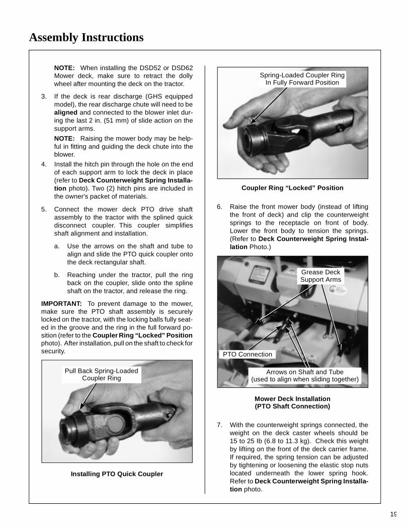
5. Connect the mower deck PTO drive shaftassembly to the tractor with the splined quickdisconnect coupler. This coupler simplifiesshaft alignment and installation.
a. Use the arrows on the shaft and tube toalign and slide the PTO quick coupler ontothe deck rectangular shaft.
b. Reaching under the tractor, pull the ringback on the coupler, slide onto the splineshaft on the tractor, and release the ring.
IMPORTANT: To prevent damage to the mower,make sure the PTO shaft assembly is securelylocked on the tractor, with the locking balls fully seat-ed in the groove and the ring in the full forward po-sition (refer to the Coupler Ring “Locked” Positionphoto). After installation, pull on the shaft to check forsecurity.
Installing PTO Quick Coupler
Coupler Ring “Locked” Position
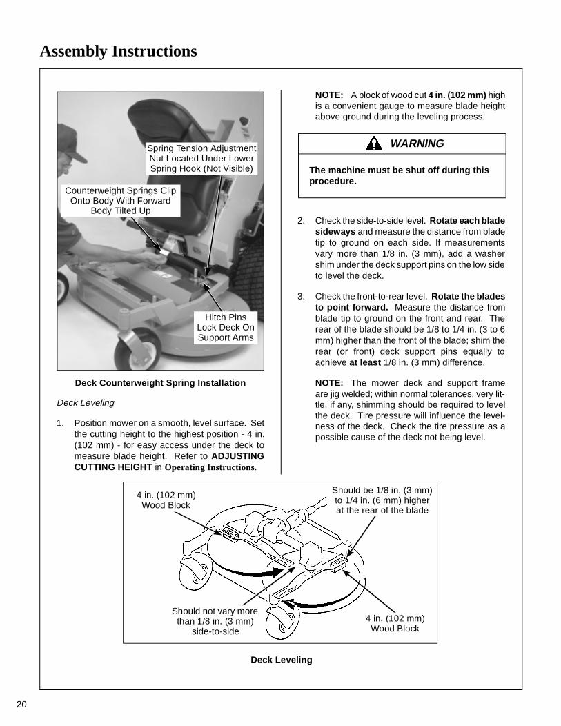
6. Raise the front mower body (instead of liftingthe front of deck) and clip the counterweightsprings to the receptacle on front of body.Lower the front body to tension the springs.(Refer to Deck Counterweight Spring Instal-lation Photo.)
Mower Deck Installation (PTO Shaft Connection)
7. With the counterweight springs connected, theweight on the deck caster wheels should be15 to 25 Ib (6.8 to 11.3 kg). Check this weightby lifting on the front of the deck carrier frame.If required, the spring tension can be adjustedby tightening or loosening the elastic stop nutslocated underneath the lower spring hook.Refer to Deck Counterweight Spring Installa-tion photo.
Pull Back Spring-LoadedCoupler Ring
Spring-Loaded Coupler RingIn Fully Forward Position
Grease DeckSupport Arms
PTO Connection
Arrows on Shaft and Tube(used to align when sliding together)
Assembly Instructions
20
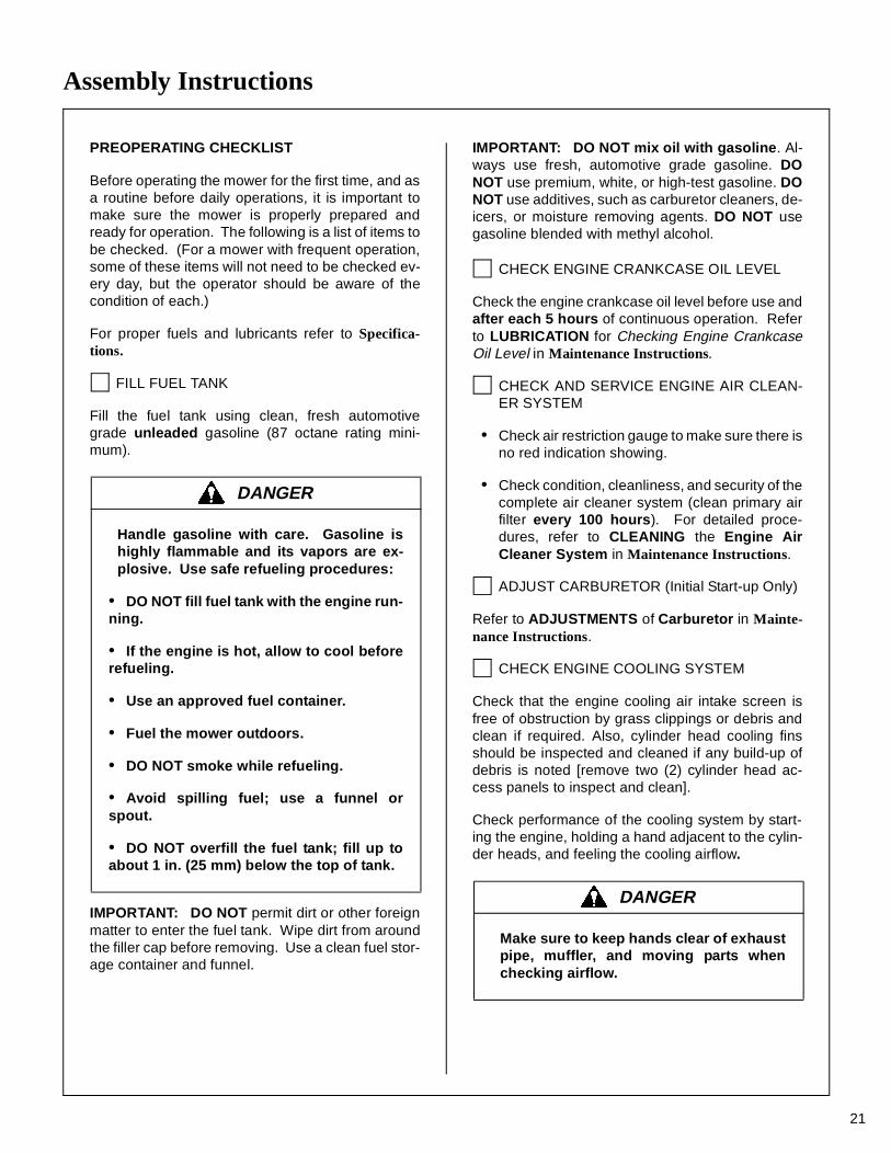
Deck Counterweight Spring Installation
Deck Leveling
1. Position mower on a smooth, level surface. Setthe cutting height to the highest position - 4 in.(102 mm) - for easy access under the deck tomeasure blade height. Refer to ADJUSTINGCUTTING HEIGHT in Operating Instructions.
NOTE: A block of wood cut 4 in. (102 mm) highis a convenient gauge to measure blade heightabove ground during the leveling process.
2. Check the side-to-side level. Rotate each bladesideways and measure the distance from bladetip to ground on each side. If measurementsvary more than 1/8 in. (3 mm), add a washershim under the deck support pins on the low sideto level the deck.
3. Check the front-to-rear level. Rotate the bladesto point forward. Measure the distance fromblade tip to ground on the front and rear. Therear of the blade should be 1/8 to 1/4 in. (3 to 6mm) higher than the front of the blade; shim therear (or front) deck support pins equally toachieve at least 1/8 in. (3 mm) difference.
NOTE: The mower deck and support frameare jig welded; within normal tolerances, very lit-tle, if any, shimming should be required to levelthe deck. Tire pressure will influence the level-ness of the deck. Check the tire pressure as apossible cause of the deck not being level.
Hitch PinsLock Deck OnSupport Arms
Counterweight Springs ClipOnto Body With Forward
Body Tilted Up
Spring Tension AdjustmentNut Located Under LowerSpring Hook (Not Visible)
WARNING
The machine must be shut off during this procedure.
Should be 1/8 in. (3 mm) to 1/4 in. (6 mm) higher at the rear of the blade
4 in. (102 mm)Wood Block
4 in. (102 mm)Wood Block
Should not vary more than 1/8 in. (3 mm)
side-to-side
Deck Leveling
Assembly Instructions
21
PREOPERATING CHECKLIST
Before operating the mower for the first time, and asa routine before daily operations, it is important tomake sure the mower is properly prepared andready for operation. The following is a list of items tobe checked. (For a mower with frequent operation,some of these items will not need to be checked ev-ery day, but the operator should be aware of thecondition of each.)
For proper fuels and lubricants refer to Specifica-tions.
FILL FUEL TANK
Fill the fuel tank using clean, fresh automotivegrade unleaded gasoline (87 octane rating mini-mum).
IMPORTANT: DO NOT permit dirt or other foreignmatter to enter the fuel tank. Wipe dirt from aroundthe filler cap before removing. Use a clean fuel stor-age container and funnel.
IMPORTANT: DO NOT mix oil with gasoline. Al-ways use fresh, automotive grade gasoline. DONOT use premium, white, or high-test gasoline. DONOT use additives, such as carburetor cleaners, de-icers, or moisture removing agents. DO NOT usegasoline blended with methyl alcohol.
CHECK ENGINE CRANKCASE OIL LEVEL
Check the engine crankcase oil level before use andafter each 5 hours of continuous operation. Referto LUBRICATION for Checking Engine CrankcaseOil Level in Maintenance Instructions.
CHECK AND SERVICE ENGINE AIR CLEAN-ER SYSTEM
• Check air restriction gauge to make sure there isno red indication showing.
• Check condition, cleanliness, and security of thecomplete air cleaner system (clean primary airfilter every 100 hours). For detailed proce-dures, refer to CLEANING the Engine AirCleaner System in Maintenance Instructions.
ADJUST CARBURETOR (Initial Start-up Only)
Refer to ADJUSTMENTS of Carburetor in Mainte-nance Instructions.
CHECK ENGINE COOLING SYSTEM
Check that the engine cooling air intake screen isfree of obstruction by grass clippings or debris andclean if required. Also, cylinder head cooling finsshould be inspected and cleaned if any build-up ofdebris is noted [remove two (2) cylinder head ac-cess panels to inspect and clean].
Check performance of the cooling system by start-ing the engine, holding a hand adjacent to the cylin-der heads, and feeling the cooling airflow.
DANGER
Handle gasoline with care. Gasoline ishighly flammable and its vapors are ex-plosive. Use safe refueling procedures:
• DO NOT fill fuel tank with the engine run-ning.
• If the engine is hot, allow to cool beforerefueling.
• Use an approved fuel container.
• Fuel the mower outdoors.
• DO NOT smoke while refueling.
• Avoid spilling fuel; use a funnel orspout.
• DO NOT overfill the fuel tank; fill up toabout 1 in. (25 mm) below the top of tank.
DANGER
Make sure to keep hands clear of exhaustpipe, muffler, and moving parts whenchecking airflow.
Assembly Instructions
22
CHECK GEAR AXLE OIL LEVEL
Refer to Gear Axle Lubrication in Maintenance In-structions.
INSPECT FOUR (4) DRIVE BELTS
Engine PTO Drive, Jackshaft Drive, HydrostaticGround Drive, and GHS Blower Drive (if equipped).
CHECK HYDROSTATIC TRANSMISSION OILLEVEL
Refer to LUBRICATION for Checking HydrostaticTransmission Fluid Level in Maintenance Instruc-tions.
CHECK BATTERY ELECTROLYTE LEVEL
Refer to CHECKING/SERVICING the Battery inMaintenance Instructions.
CHECK FUNCTIONS OF INSTRUMENT PANELAND WARNING HORN
Turn the ignition key to the RUN position. Voltmeter,Oil Pressure Light, and Warning Horn should all op-erate, indicating normal function.
CHECK TIRE PRESSURE
Deck Caster Wheel = 20 PSI (137 kPa)Drive = 15 PSI (103 kPa)Rear = 20 PSI (137 kPa)
CHECK AND CLEAN GRASS BUILDUP UN-DERNEATH MOWER DECK (and inside GHSblower, if equipped)
Refer to CLEANING the GHS Blower in Mainte-nance Instructions for blower cleaning information.
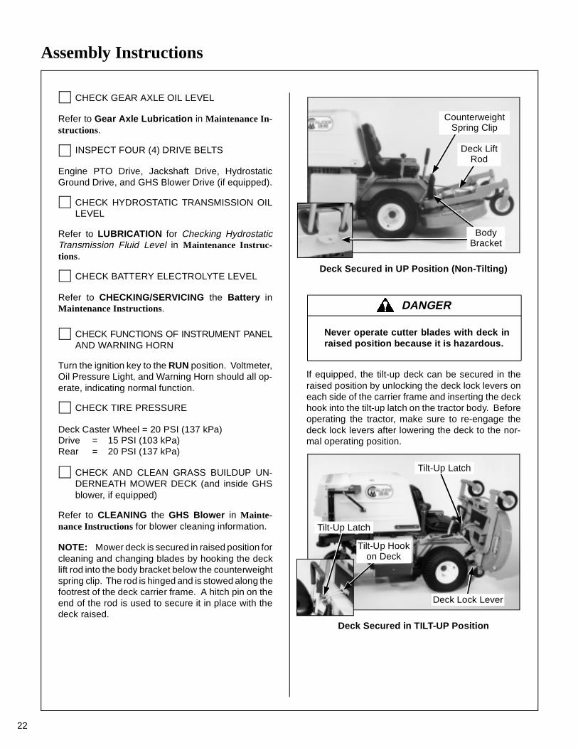
NOTE: Mower deck is secured in raised position forcleaning and changing blades by hooking the decklift rod into the body bracket below the counterweightspring clip. The rod is hinged and is stowed along thefootrest of the deck carrier frame. A hitch pin on theend of the rod is used to secure it in place with thedeck raised.
Deck Secured in UP Position (Non-Tilting)
If equipped, the tilt-up deck can be secured in theraised position by unlocking the deck lock levers oneach side of the carrier frame and inserting the deckhook into the tilt-up latch on the tractor body. Beforeoperating the tractor, make sure to re-engage thedeck lock levers after lowering the deck to the nor-mal operating position.
Deck Secured in TILT-UP Position
DANGER
Never operate cutter blades with deck inraised position because it is hazardous.
BodyBracket
CounterweightSpring Clip
Deck LiftRod
Deck Lock Lever
Tilt-Up Latch
Tilt-Up Latch
Tilt-Up Hookon Deck
Assembly Instructions
CHECK MOWER BLADE CONDITION, SHARP-NESS, AND SECURITY OF MOUNTING
The blade mounting nut should be tightened to60 ft-lb (81.3 N⋅m). If blade sharpening is required,refer to CHECKING/SERVICING for SharpenMower Blades in Maintenance Instructions.
ADJUST MOWER CUTTING HEIGHT, IF RE-QUIRED
Position the hitch pins in the four deck support pins.Refer to the “Cutting Height Adjustment” decal onthe deck gearbox cover.
PERFORM ANY ADDITIONAL PROCEDUREScalled for on the MAINTENANCE SCHEDULECHART in Maintenance Instructions.
CAUTION
Do not operate machine with deck tilt-uppivot joint unlocked.
DANGER
Do not operate the mower with deck in tilt-up position. Do not move the tractor withthe deck in the tilt-up position.
23
Operating Instructions
24
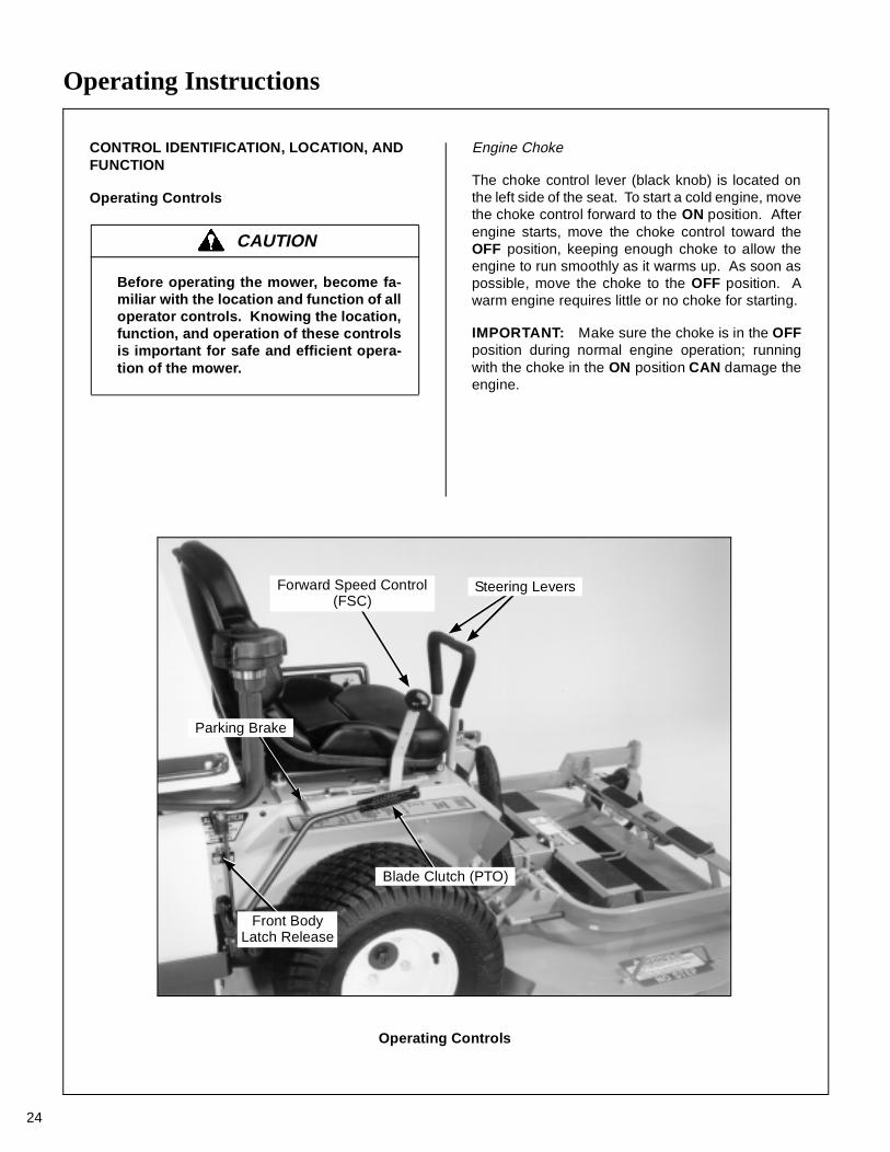
CONTROL IDENTIFICATION, LOCATION, AND FUNCTION
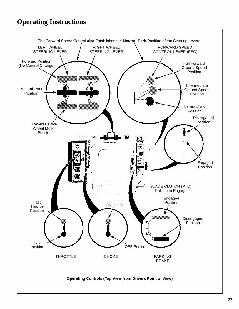
Operating Controls
Engine Choke
The choke control lever (black knob) is located onthe left side of the seat. To start a cold engine, movethe choke control forward to the ON position. Afterengine starts, move the choke control toward theOFF position, keeping enough choke to allow theengine to run smoothly as it warms up. As soon aspossible, move the choke to the OFF position. Awarm engine requires little or no choke for starting.
IMPORTANT: Make sure the choke is in the OFFposition during normal engine operation; runningwith the choke in the ON position CAN damage theengine.
CAUTION
Before operating the mower, become fa-miliar with the location and function of alloperator controls. Knowing the location,function, and operation of these controlsis important for safe and efficient opera-tion of the mower.
Operating Controls
Forward Speed Control(FSC)
Steering Levers
Parking Brake
Front BodyLatch Release
Blade Clutch (PTO)
Operating Instructions
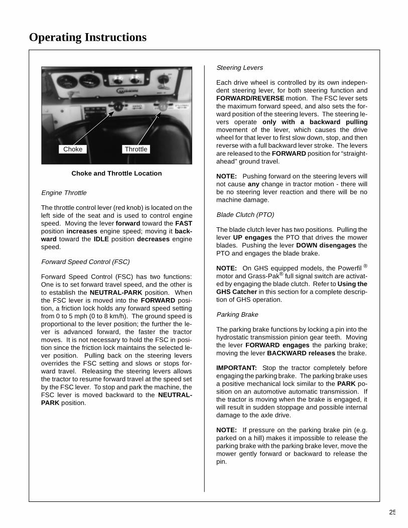
25
Choke and Throttle Location
Engine Throttle
The throttle control lever (red knob) is located on theleft side of the seat and is used to control enginespeed. Moving the lever forward toward the FASTposition increases engine speed; moving it back-ward toward the IDLE position decreases enginespeed.
Forward Speed Control (FSC)
Forward Speed Control (FSC) has two functions:One is to set forward travel speed, and the other isto establish the NEUTRAL-PARK position. Whenthe FSC lever is moved into the FORWARD posi-tion, a friction lock holds any forward speed settingfrom 0 to 5 mph (0 to 8 km/h). The ground speed isproportional to the lever position; the further the le-ver is advanced forward, the faster the tractormoves. It is not necessary to hold the FSC in posi-tion since the friction lock maintains the selected le-ver position. Pulling back on the steering leversoverrides the FSC setting and slows or stops for-ward travel. Releasing the steering levers allowsthe tractor to resume forward travel at the speed setby the FSC lever. To stop and park the machine, theFSC lever is moved backward to the NEUTRAL-PARK position.
Steering Levers
Each drive wheel is controlled by its own indepen-dent steering lever, for both steering function andFORWARD/REVERSE motion. The FSC lever setsthe maximum forward speed, and also sets the for-ward position of the steering levers. The steering le-vers operate only with a backward pullingmovement of the lever, which causes the drivewheel for that lever to first slow down, stop, and thenreverse with a full backward lever stroke. The leversare released to the FORWARD position for “straight-ahead” ground travel.
NOTE: Pushing forward on the steering levers willnot cause any change in tractor motion - there willbe no steering lever reaction and there will be nomachine damage.
Blade Clutch (PTO)
The blade clutch lever has two positions. Pulling thelever UP engages the PTO that drives the mowerblades. Pushing the lever DOWN disengages thePTO and engages the blade brake.
NOTE: On GHS equipped models, the Powerfil ®
motor and Grass-Pak® full signal switch are activat-ed by engaging the blade clutch. Refer to Using theGHS Catcher in this section for a complete descrip-tion of GHS operation.
Parking Brake
The parking brake functions by locking a pin into thehydrostatic transmission pinion gear teeth. Movingthe lever FORWARD engages the parking brake;moving the lever BACKWARD releases the brake.
IMPORTANT: Stop the tractor completely beforeengaging the parking brake. The parking brake usesa positive mechanical lock similar to the PARK po-sition on an automotive automatic transmission. Ifthe tractor is moving when the brake is engaged, itwill result in sudden stoppage and possible internaldamage to the axle drive.
NOTE: If pressure on the parking brake pin (e.g.parked on a hill) makes it impossible to release theparking brake with the parking brake lever, move themower gently forward or backward to release thepin.
Choke Throttle
Operating Instructions
26
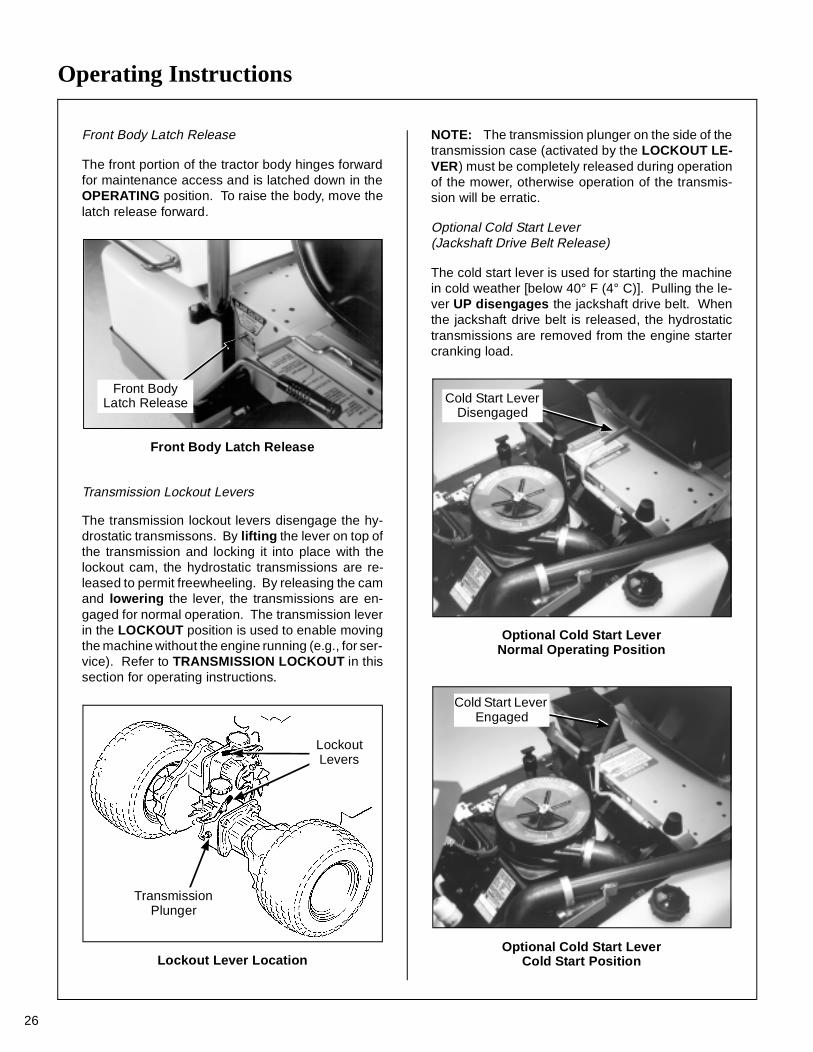
Front Body Latch Release
The front portion of the tractor body hinges forwardfor maintenance access and is latched down in theOPERATING position. To raise the body, move thelatch release forward.
Front Body Latch Release
Transmission Lockout Levers
The transmission lockout levers disengage the hy-drostatic transmissons. By lifting the lever on top ofthe transmission and locking it into place with thelockout cam, the hydrostatic transmissions are re-leased to permit freewheeling. By releasing the camand lowering the lever, the transmissions are en-gaged for normal operation. The transmission leverin the LOCKOUT position is used to enable movingthe machine without the engine running (e.g., for ser-vice). Refer to TRANSMISSION LOCKOUT in thissection for operating instructions.
Lockout Lever Location
NOTE: The transmission plunger on the side of thetransmission case (activated by the LOCKOUT LE-VER) must be completely released during operationof the mower, otherwise operation of the transmis-sion will be erratic.
Optional Cold Start Lever (Jackshaft Drive Belt Release)
The cold start lever is used for starting the machinein cold weather [below 40° F (4° C)]. Pulling the le-ver UP disengages the jackshaft drive belt. Whenthe jackshaft drive belt is released, the hydrostatictransmissions are removed from the engine startercranking load.
Optional Cold Start LeverNormal Operating Position
Optional Cold Start LeverCold Start Position
Front BodyLatch Release
TransmissionPlunger
LockoutLevers
Cold Start Lever Disengaged
Cold Start Lever Engaged
Operating Instructions
27
CHOKETHROTTLE
BLADE CLUTCH (PTO)Pull Up to Engage
PARKINGBRAKE
IntermediateGround Speed
Position
The Forward Speed Control also Establishes the Neutral-Park Position of the Steering Levers
LEFT WHEELSTEERING LEVER
RIGHT WHEELSTEERING LEVER
Reverse DriveWheel Motion
Position
FORWARD SPEEDCONTROL LEVER (FSC)
Full ForwardGround Speed
Position
Neutral-ParkPosition
DisengagedPosition
EngagedPosition
EngagedPosition
DisengagedPosition
OFF Position
ON Position
IdlePosition
FastThrottlePosition
Operating Controls (Top View from Drivers Point of View)
Neutral-ParkPosition
Forward Position(No Control Change)
Operating Instructions
28
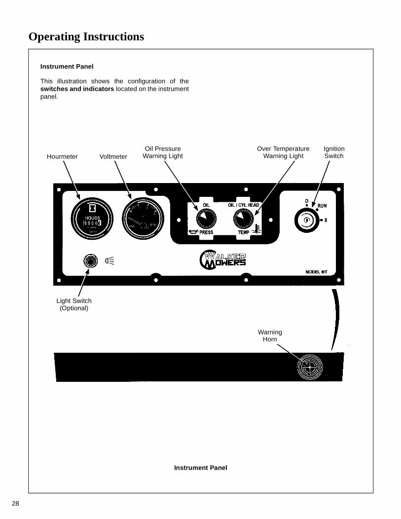
Instrument Panel
Instrument Panel
This illustration shows the configuration of theswitches and indicators located on the instrumentpanel.
Hourmeter VoltmeterOil Pressure
Warning LightOver Temperature
Warning LightIgnitionSwitch
Light Switch(Optional)
WarningHorn
Operating Instructions
29
Hourmeter
The hourmeter displays operating time accumu-lated while the ignition switch is in the ON position.
Voltmeter
The voltmeter displays battery and charging systemvoltage. An indication of low or high voltage (below11.5 volts or above 15.5 volts) indicates an electri-cal system failure. The cause of the failure shouldbe determined and corrected.
Oil Pressure Warning Light
The oil pressure warning light indicates that engineoil pressure is below the safe operating range [below3 to 5 PSI (21 to 34 kPa)]. This light (and warninghorn) will come on when the ignition is turned ON, butshould go off after the engine is started. If the lightfails to come on when the ignition switch is turned ON,it could indicate a burned out bulb. If the light comeson during engine operation, stop the engine imme-diately and correct the source of the problem beforefurther engine operation.
IMPORTANT: Continued operation of the enginewith an illuminated oil pressure warning light MAYcause severe engine damage (if a low oil pressurecondition exists).
Over Temperature Warning Light
The over temperature warning light indicates thatengine oil temperature and/or cylinder head temper-ature are above the safe operating limit and the en-gine is overheating [above 305° F (152° C) oil or450° F (232° C) cylinder head]. If this light comeson, there may be a problem with:
• Engine cooling system (material packed into cyl-inder head cooling fins, clogged air intake screen)
• Low oil level in crankcase
Stop the engine and correct the source of the prob-lem before further operation.
IMPORTANT: Continued operation of the enginewith an illuminated over temperature warning lightMAY cause severe engine damage (if a high oil tem-perature or head temperature condition exists).
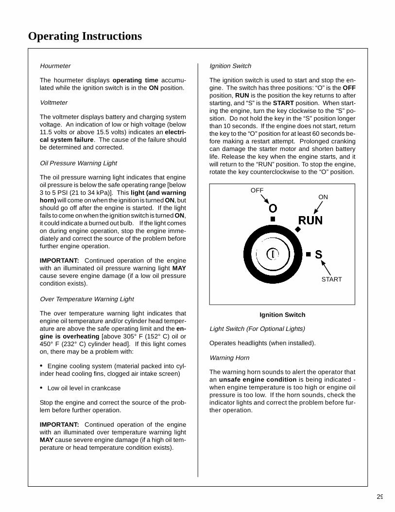
Ignition Switch
The ignition switch is used to start and stop the en-gine. The switch has three positions: “O” is the OFFposition, RUN is the position the key returns to afterstarting, and “S” is the START position. When start-ing the engine, turn the key clockwise to the “S” po-sition. Do not hold the key in the “S” position longerthan 10 seconds. If the engine does not start, returnthe key to the “O” position for at least 60 seconds be-fore making a restart attempt. Prolonged crankingcan damage the starter motor and shorten batterylife. Release the key when the engine starts, and itwill return to the “RUN” position. To stop the engine,rotate the key counterclockwise to the “O” position.
Ignition Switch
Light Switch (For Optional Lights)
Operates headlights (when installed).
Warning Horn
The warning horn sounds to alert the operator thatan unsafe engine condition is being indicated -when engine temperature is too high or engine oilpressure is too low. If the horn sounds, check theindicator lights and correct the problem before fur-ther operation.
ONOFF
START
Operating Instructions
30
STARTING THE ENGINE
1. Before attempting to start the engine, makesure the operator is in the seat, the ForwardSpeed Control is in NEUTRAL-PARK position,and the blade clutch and parking brake areDISENGAGED.
NOTE: Release parking brake to prevent extraload on the starter if the transmission neutral isslightly out of adjustment.
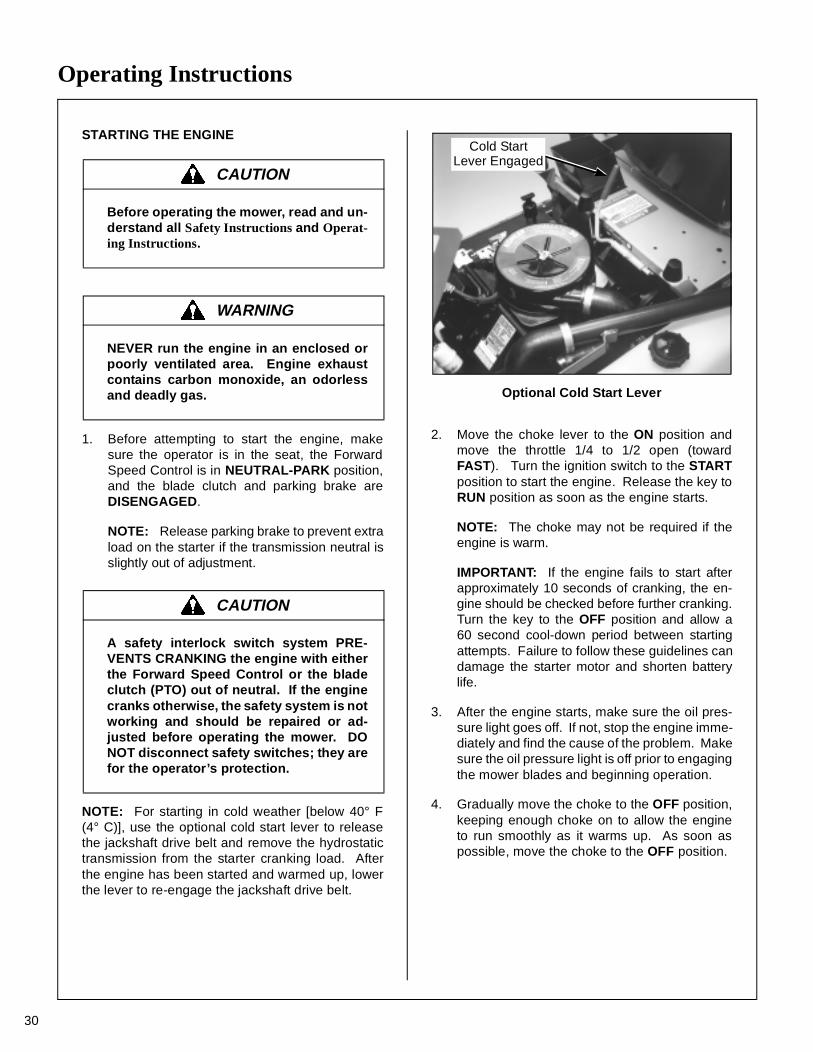
NOTE: For starting in cold weather [below 40° F(4° C)], use the optional cold start lever to releasethe jackshaft drive belt and remove the hydrostatictransmission from the starter cranking load. Afterthe engine has been started and warmed up, lowerthe lever to re-engage the jackshaft drive belt.
Optional Cold Start Lever
2. Move the choke lever to the ON position andmove the throttle 1/4 to 1/2 open (towardFAST). Turn the ignition switch to the STARTposition to start the engine. Release the key toRUN position as soon as the engine starts.
NOTE: The choke may not be required if theengine is warm.
IMPORTANT: If the engine fails to start afterapproximately 10 seconds of cranking, the en-gine should be checked before further cranking.Turn the key to the OFF position and allow a60 second cool-down period between startingattempts. Failure to follow these guidelines candamage the starter motor and shorten batterylife.
3. After the engine starts, make sure the oil pres-sure light goes off. If not, stop the engine imme-diately and find the cause of the problem. Makesure the oil pressure light is off prior to engagingthe mower blades and beginning operation.
4. Gradually move the choke to the OFF position,keeping enough choke on to allow the engineto run smoothly as it warms up. As soon aspossible, move the choke to the OFF position.
CAUTION
Before operating the mower, read and un-derstand all Safety Instructions and Operat-ing Instructions.
WARNING
NEVER run the engine in an enclosed orpoorly ventilated area. Engine exhaustcontains carbon monoxide, an odorlessand deadly gas.
CAUTION
A safety interlock switch system PRE-VENTS CRANKING the engine with eitherthe Forward Speed Control or the bladeclutch (PTO) out of neutral. If the enginecranks otherwise, the safety system is notworking and should be repaired or ad-justed before operating the mower. DONOT disconnect safety switches; they arefor the operator’s protection.
Cold StartLever Engaged

Operating Instructions
31
IMPORTANT: Make sure the choke is in the OFFposition during normal engine operation; runningwith the choke in the ON position CAN damage theengine.
ADJUSTING GROUND SPEED AND STEERING
IMPORTANT: If the DSD52 or DSD62 Mowerdeck is installed on the tractor, make sure the dollywheel is retracted BEFORE moving.
1. Move the FSC out of NEUTRAL-PARK positionto the desired forward speed. DO NOT hold for-ward on steering levers. It is not necessary tohold the FSC lever in position since a frictionlock maintains the selected lever position (andforward travel speed).
NOTE: If the FSC lever will not stay in theselected position, the friction lock needs to beadjusted. Refer to ADJUSTMENTS of ForwardSpeed Control Friction Lock in MaintenanceInstructions.
2. Steer by pulling the lever on the side of desireddirection of turn, e.g., pull the LH lever to turnleft. To minimize the possibility of overcontrol,use only one hand on both steering levers.
CAUTION
Learn to START, STOP, and MANEUVERthe mower in a large, open area.
If the operator has not operated a ma-chine with LEVER STEERING OR DUALHYDROSTATIC TRANSMISSIONS, steer-ing and ground operation should belearned and practiced until the operator iscompletely comfortable handling the ma-chine BEFORE ATTEMPTING TO MOW.
DANGER
Keep feet on footrests all times when themachine is moving.
Beginning Recommendations are:
♦ Learn operation of the mower in an openarea away from buildings, fences, and ob-structions. Learn operation on flat groundBEFORE operating on slopes.
♦ Start maneuvering the mower with SLOWengine speed and SLOW Forward SpeedControl setting until familiar with all operat-ing characteristics.
♦ Remember it is not necessary to hold thesteering levers forward (a unique Walkerfeature); always PULL on the levers forsteering or for reverse motion of the mower.
♦ Learn to operate the mower with your lefthand on the steering levers and right handon Forward Speed Control. The use of twohands on the steering levers tends to causeovercontrol.
♦ Learn to operate the steering levers withsmooth action. Jerky movements are hardon the transmission and lawn. For sharpturns, do not allow the inside wheel to stopand twist on the grass. Pull the steering le-ver controlling the inside wheel into reversefor a smooth “rolling” turn (one wheel roll-ing forward while the other rolls backward).
♦ Practice maneuvering the mower untilyou can make it go exactly where you areaiming.
♦ Remember, for an emergency stop, or incase of loss of control, machine movementcan always be stopped quickly by pullingthe Forward Speed Control into the NEU-TRAL-PARK position.
Operating Instructions
32
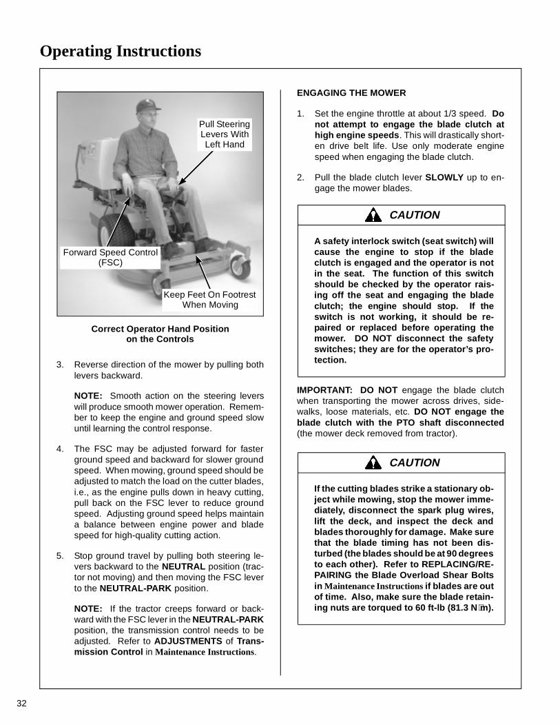
Correct Operator Hand Positionon the Controls
3. Reverse direction of the mower by pulling bothlevers backward.
NOTE: Smooth action on the steering leverswill produce smooth mower operation. Remem-ber to keep the engine and ground speed slowuntil learning the control response.
4. The FSC may be adjusted forward for fasterground speed and backward for slower groundspeed. When mowing, ground speed should beadjusted to match the load on the cutter blades,i.e., as the engine pulls down in heavy cutting,pull back on the FSC lever to reduce groundspeed. Adjusting ground speed helps maintaina balance between engine power and bladespeed for high-quality cutting action.
5. Stop ground travel by pulling both steering le-vers backward to the NEUTRAL position (trac-tor not moving) and then moving the FSC leverto the NEUTRAL-PARK position.
NOTE: If the tractor creeps forward or back-ward with the FSC lever in the NEUTRAL-PARKposition, the transmission control needs to beadjusted. Refer to ADJUSTMENTS of Trans-mission Control in Maintenance Instructions.
ENGAGING THE MOWER
1. Set the engine throttle at about 1/3 speed. Donot attempt to engage the blade clutch athigh engine speeds. This will drastically short-en drive belt life. Use only moderate enginespeed when engaging the blade clutch.
2. Pull the blade clutch lever SLOWLY up to en-gage the mower blades.
IMPORTANT: DO NOT engage the blade clutchwhen transporting the mower across drives, side-walks, loose materials, etc. DO NOT engage theblade clutch with the PTO shaft disconnected(the mower deck removed from tractor).
Pull Steering Levers With Left Hand
Forward Speed Control (FSC)
Keep Feet On Footrest When Moving
CAUTION
A safety interlock switch (seat switch) willcause the engine to stop if the bladeclutch is engaged and the operator is notin the seat. The function of this switchshould be checked by the operator rais-ing off the seat and engaging the bladeclutch; the engine should stop. If theswitch is not working, it should be re-paired or replaced before operating themower. DO NOT disconnect the safetyswitches; they are for the operator’s pro-tection.
CAUTION
If the cutting blades strike a stationary ob-ject while mowing, stop the mower imme-diately, disconnect the spark plug wires,lift the deck, and inspect the deck andblades thoroughly for damage. Make surethat the blade timing has not been dis-turbed (the blades should be at 90 degreesto each other). Refer to REPLACING/RE-PAIRING the Blade Overload Shear Boltsin Maintenance Instructions if blades are outof time. Also, make sure the blade retain-ing nuts are torqued to 60 ft-lb (81.3 N⋅m).
Operating Instructions
33
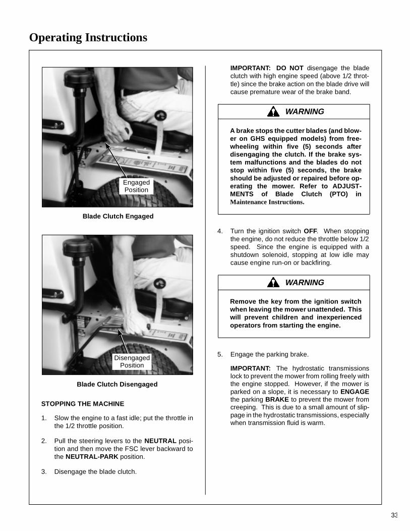
Blade Clutch Engaged
Blade Clutch Disengaged
STOPPING THE MACHINE
1. Slow the engine to a fast idle; put the throttle inthe 1/2 throttle position.
2. Pull the steering levers to the NEUTRAL posi-tion and then move the FSC lever backward tothe NEUTRAL-PARK position.
3. Disengage the blade clutch.
IMPORTANT: DO NOT disengage the bladeclutch with high engine speed (above 1/2 throt-tle) since the brake action on the blade drive willcause premature wear of the brake band.
4. Turn the ignition switch OFF. When stoppingthe engine, do not reduce the throttle below 1/2speed. Since the engine is equipped with ashutdown solenoid, stopping at low idle maycause engine run-on or backfiring.
5. Engage the parking brake.
IMPORTANT: The hydrostatic transmissionslock to prevent the mower from rolling freely withthe engine stopped. However, if the mower isparked on a slope, it is necessary to ENGAGEthe parking BRAKE to prevent the mower fromcreeping. This is due to a small amount of slip-page in the hydrostatic transmissions, especiallywhen transmission fluid is warm.
EngagedPosition
DisengagedPosition
WARNING
A brake stops the cutter blades (and blow-er on GHS equipped models) from free-wheeling within five (5) seconds afterdisengaging the clutch. If the brake sys-tem malfunctions and the blades do notstop within five (5) seconds, the brakeshould be adjusted or repaired before op-erating the mower. Refer to ADJUST-MENTS of Blade Clutch (PTO) inMaintenance Instructions.
WARNING
Remove the key from the ignition switchwhen leaving the mower unattended. Thiswill prevent children and inexperiencedoperators from starting the engine.
Operating Instructions
34
ADJUSTING CUTTING HEIGHT
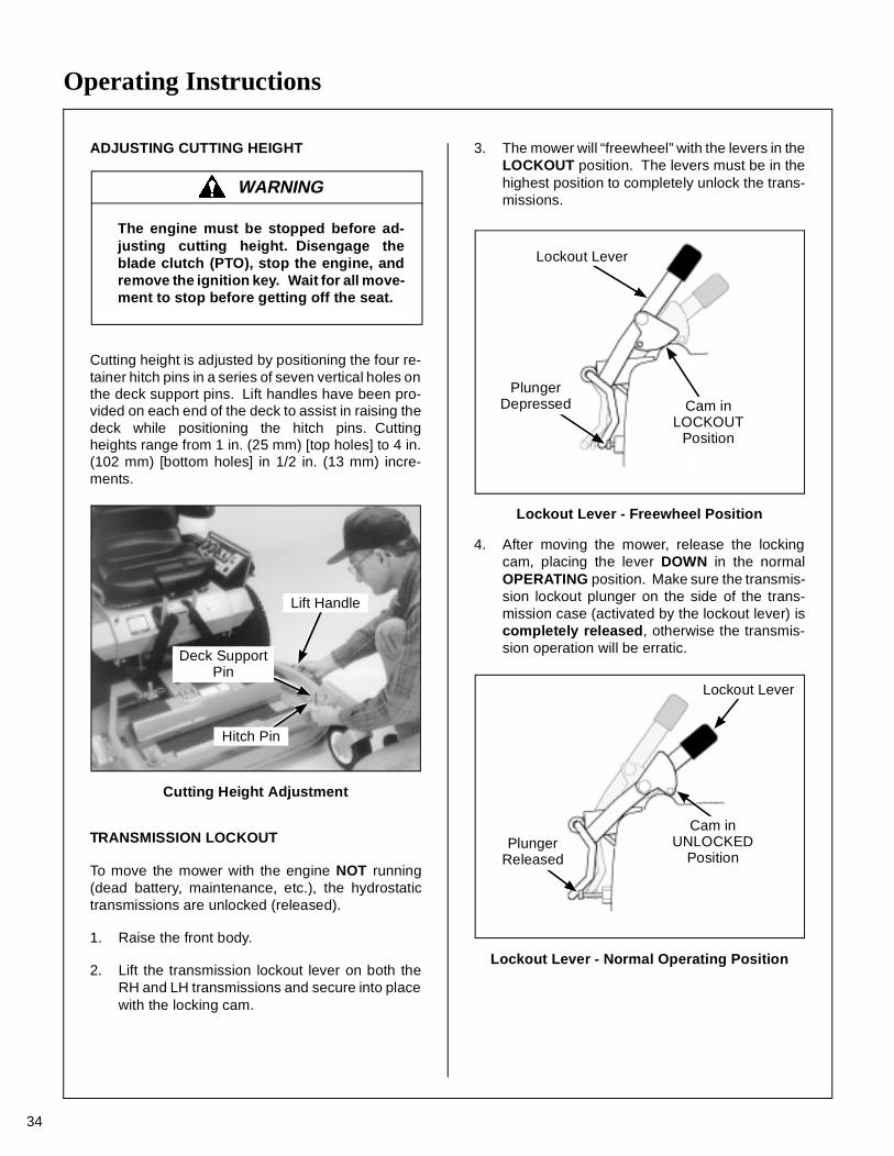
Cutting height is adjusted by positioning the four re-tainer hitch pins in a series of seven vertical holes onthe deck support pins. Lift handles have been pro-vided on each end of the deck to assist in raising thedeck while positioning the hitch pins. Cuttingheights range from 1 in. (25 mm) [top holes] to 4 in.(102 mm) [bottom holes] in 1/2 in. (13 mm) incre-ments.
Cutting Height Adjustment
TRANSMISSION LOCKOUT
To move the mower with the engine NOT running(dead battery, maintenance, etc.), the hydrostatictransmissions are unlocked (released).
1. Raise the front body.
2. Lift the transmission lockout lever on both theRH and LH transmissions and secure into placewith the locking cam.
3. The mower will “freewheel” with the levers in theLOCKOUT position. The levers must be in thehighest position to completely unlock the trans-missions.
Lockout Lever - Freewheel Position
4. After moving the mower, release the lockingcam, placing the lever DOWN in the normalOPERATING position. Make sure the transmis-sion lockout plunger on the side of the trans-mission case (activated by the lockout lever) iscompletely released, otherwise the transmis-sion operation will be erratic.
Lockout Lever - Normal Operating Position
WARNING
The engine must be stopped before ad-justing cutting height. Disengage theblade clutch (PTO), stop the engine, andremove the ignition key. Wait for all move-ment to stop before getting off the seat.
Lift Handle
Deck SupportPin
Hitch Pin
Cam inLOCKOUT
Position
PlungerDepressed
Lockout Lever
Cam inUNLOCKED
Position
Lockout Lever
PlungerReleased
Operating Instructions
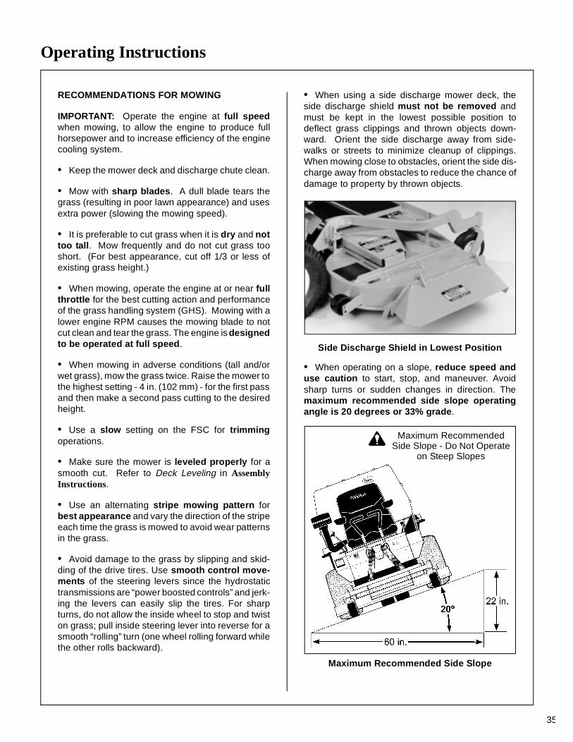
RECOMMENDATIONS FOR MOWING
IMPORTANT: Operate the engine at full speedwhen mowing, to allow the engine to produce fullhorsepower and to increase efficiency of the enginecooling system.
• Keep the mower deck and discharge chute clean.
• Mow with sharp blades. A dull blade tears thegrass (resulting in poor lawn appearance) and usesextra power (slowing the mowing speed).
• It is preferable to cut grass when it is dry and nottoo tall. Mow frequently and do not cut grass tooshort. (For best appearance, cut off 1/3 or less ofexisting grass height.)
• When mowing, operate the engine at or near fullthrottle for the best cutting action and performanceof the grass handling system (GHS). Mowing with alower engine RPM causes the mowing blade to notcut clean and tear the grass. The engine is designedto be operated at full speed.
• When mowing in adverse conditions (tall and/orwet grass), mow the grass twice. Raise the mower tothe highest setting - 4 in. (102 mm) - for the first passand then make a second pass cutting to the desiredheight.
• Use a slow setting on the FSC for trimmingoperations.
• Make sure the mower is leveled properly for asmooth cut. Refer to Deck Leveling in AssemblyInstructions.
• Use an alternating stripe mowing pattern forbest appearance and vary the direction of the stripeeach time the grass is mowed to avoid wear patternsin the grass.
• Avoid damage to the grass by slipping and skid-ding of the drive tires. Use smooth control move-ments of the steering levers since the hydrostatictransmissions are “power boosted controls” and jerk-ing the levers can easily slip the tires. For sharpturns, do not allow the inside wheel to stop and twiston grass; pull inside steering lever into reverse for asmooth “rolling” turn (one wheel rolling forward whilethe other rolls backward).
• When using a side discharge mower deck, theside discharge shield must not be removed andmust be kept in the lowest possible position todeflect grass clippings and thrown objects down-ward. Orient the side discharge away from side-walks or streets to minimize cleanup of clippings.When mowing close to obstacles, orient the side dis-charge away from obstacles to reduce the chance ofdamage to property by thrown objects.
Side Discharge Shield in Lowest Position
• When operating on a slope, reduce speed anduse caution to start, stop, and maneuver. Avoidsharp turns or sudden changes in direction. Themaximum recommended side slope operatingangle is 20 degrees or 33% grade.
Maximum Recommended Side Slope
Maximum RecommendedSide Slope - Do Not Operate
on Steep Slopes
35
Operating Instructions
36
RECOMMENDATIONS FOR TILT-UP DECK OPERATION/TRANSPORT
To avoid potential deck and/or tractor damage whileusing the tilt-up deck, the following recommenda-tions are offered:
• Do not move the tractor with the deck in the tilt-up position since both the roller wheels (on the backof the deck) and the GHS discharge chute may bedamaged by moving the tractor. The tilt-up configu-ration should only be used when the tractor isparked.
• The tractor body should never be tilted for-ward with the deck in the tilt-up position. This cancause the deck to unhook from the tractor and fallwith considerable force, potentially causing deck ortractor damage and/or bodily injury.
• When transporting a tractor with the deck in thetilt-up position (on a truck or trailer), the deckshould be secured to the vehicle with a strap orrope (stop vertical movement). This will prevent thedeck from bouncing on the rear roller wheels (caus-ing breakage). This will also prevent the deck fromunhooking from the tractor and falling, potentiallycausing deck or tractor damage. Damage to otheritems parked in front of the deck may also occur.
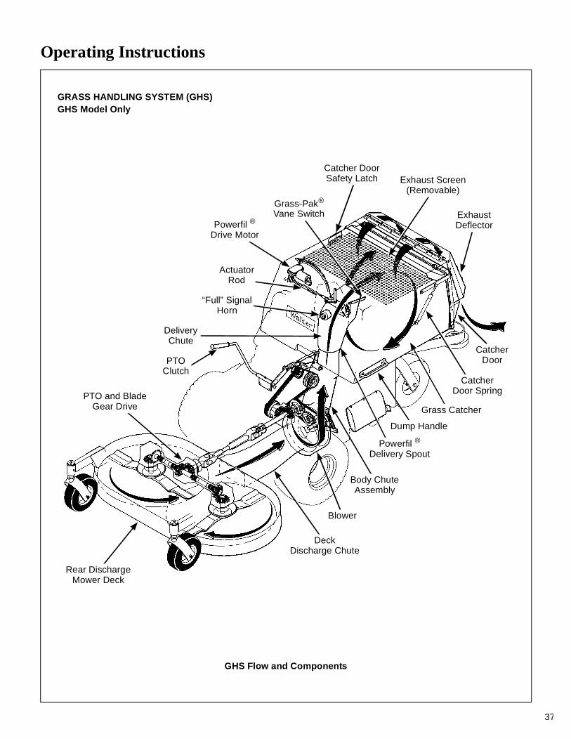
Operating Instructions
37
GRASS HANDLING SYSTEM (GHS)GHS Model Only
GHS Flow and Components
PTO and BladeGear Drive
PTOClutch
Rear DischargeMower Deck
DeckDischarge Chute
Blower
Body ChuteAssembly
Powerfil ®
Delivery Spout
Grass Catcher
CatcherDoor Spring
CatcherDoor
ExhaustDeflector
Exhaust Screen(Removable)
Catcher DoorSafety Latch
Grass-Pak®
Vane Switch
DeliveryChute
“Full” SignalHorn
ActuatorRod
Powerfil ®
Drive Motor
Dump Handle
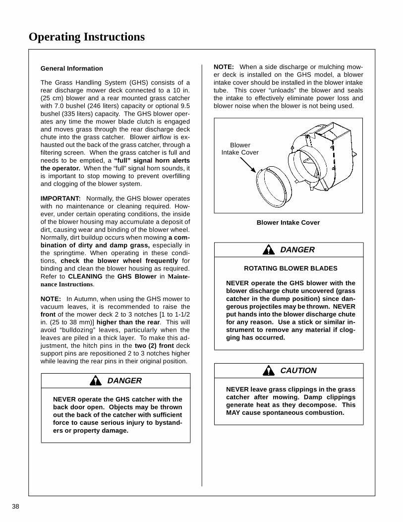
Operating Instructions
38
General Information
The Grass Handling System (GHS) consists of arear discharge mower deck connected to a 10 in.(25 cm) blower and a rear mounted grass catcherwith 7.0 bushel (246 liters) capacity or optional 9.5bushel (335 liters) capacity. The GHS blower oper-ates any time the mower blade clutch is engagedand moves grass through the rear discharge deckchute into the grass catcher. Blower airflow is ex-hausted out the back of the grass catcher, through afiltering screen. When the grass catcher is full andneeds to be emptied, a “full” signal horn alertsthe operator. When the “full” signal horn sounds, itis important to stop mowing to prevent overfillingand clogging of the blower system.
IMPORTANT: Normally, the GHS blower operateswith no maintenance or cleaning required. How-ever, under certain operating conditions, the insideof the blower housing may accumulate a deposit ofdirt, causing wear and binding of the blower wheel.Normally, dirt buildup occurs when mowing a com-bination of dirty and damp grass, especially inthe springtime. When operating in these condi-tions, check the blower wheel frequently forbinding and clean the blower housing as required.Refer to CLEANING the GHS Blower in Mainte-nance Instructions.
NOTE: In Autumn, when using the GHS mower tovacuum leaves, it is recommended to raise thefront of the mower deck 2 to 3 notches [1 to 1-1/2in. (25 to 38 mm)] higher than the rear. This willavoid “bulldozing” leaves, particularly when theleaves are piled in a thick layer. To make this ad-justment, the hitch pins in the two (2) front decksupport pins are repositioned 2 to 3 notches higherwhile leaving the rear pins in their original position.
NOTE: When a side discharge or mulching mow-er deck is installed on the GHS model, a blowerintake cover should be installed in the blower intaketube. This cover “unloads” the blower and sealsthe intake to effectively eliminate power loss andblower noise when the blower is not being used.
Blower Intake Cover
DANGER
NEVER operate the GHS catcher with theback door open. Objects may be thrownout the back of the catcher with sufficientforce to cause serious injury to bystand-ers or property damage.
DANGER
ROTATING BLOWER BLADES
NEVER operate the GHS blower with theblower discharge chute uncovered (grasscatcher in the dump position) since dan-gerous projectiles may be thrown. NEVERput hands into the blower discharge chutefor any reason. Use a stick or similar in-strument to remove any material if clog-ging has occurred.
CAUTION
NEVER leave grass clippings in the grasscatcher after mowing. Damp clippingsgenerate heat as they decompose. ThisMAY cause spontaneous combustion.
BlowerIntake Cover
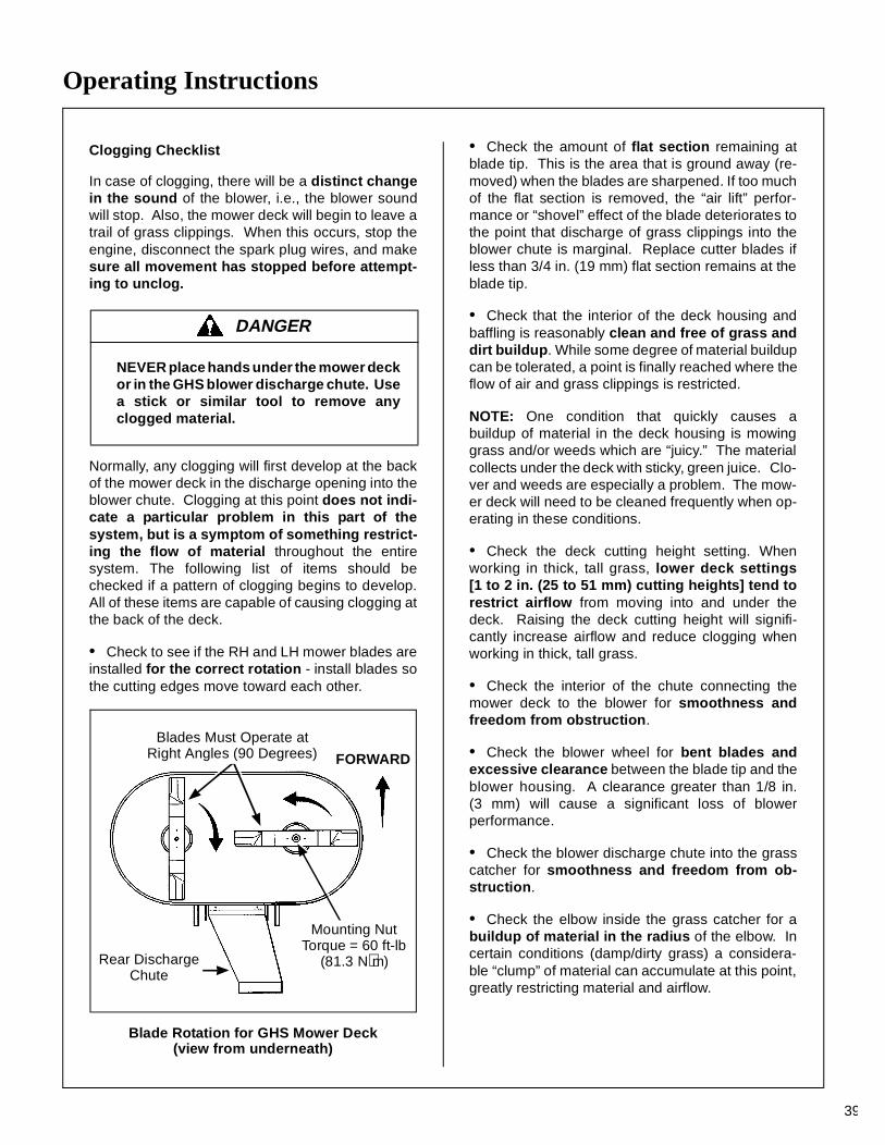
Operating Instructions
39
Clogging Checklist
In case of clogging, there will be a distinct changein the sound of the blower, i.e., the blower soundwill stop. Also, the mower deck will begin to leave atrail of grass clippings. When this occurs, stop theengine, disconnect the spark plug wires, and makesure all movement has stopped before attempt-ing to unclog.
Normally, any clogging will first develop at the backof the mower deck in the discharge opening into theblower chute. Clogging at this point does not indi-cate a particular problem in this part of thesystem, but is a symptom of something restrict-ing the flow of material throughout the entiresystem. The following list of items should bechecked if a pattern of clogging begins to develop.All of these items are capable of causing clogging atthe back of the deck.
• Check to see if the RH and LH mower blades areinstalled for the correct rotation - install blades sothe cutting edges move toward each other.
Blade Rotation for GHS Mower Deck(view from underneath)
• Check the amount of flat section remaining atblade tip. This is the area that is ground away (re-moved) when the blades are sharpened. If too muchof the flat section is removed, the “air lift” perfor-mance or “shovel” effect of the blade deteriorates tothe point that discharge of grass clippings into theblower chute is marginal. Replace cutter blades ifless than 3/4 in. (19 mm) flat section remains at theblade tip.
• Check that the interior of the deck housing andbaffling is reasonably clean and free of grass anddirt buildup. While some degree of material buildupcan be tolerated, a point is finally reached where theflow of air and grass clippings is restricted.
NOTE: One condition that quickly causes abuildup of material in the deck housing is mowinggrass and/or weeds which are “juicy.” The materialcollects under the deck with sticky, green juice. Clo-ver and weeds are especially a problem. The mow-er deck will need to be cleaned frequently when op-erating in these conditions.
• Check the deck cutting height setting. Whenworking in thick, tall grass, lower deck settings[1 to 2 in. (25 to 51 mm) cutting heights] tend torestrict airflow from moving into and under thedeck. Raising the deck cutting height will signifi-cantly increase airflow and reduce clogging whenworking in thick, tall grass.
• Check the interior of the chute connecting themower deck to the blower for smoothness andfreedom from obstruction.
• Check the blower wheel for bent blades andexcessive clearance between the blade tip and theblower housing. A clearance greater than 1/8 in.(3 mm) will cause a significant loss of blowerperformance.
• Check the blower discharge chute into the grasscatcher for smoothness and freedom from ob-struction.
• Check the elbow inside the grass catcher for abuildup of material in the radius of the elbow. Incertain conditions (damp/dirty grass) a considera-ble “clump” of material can accumulate at this point,greatly restricting material and airflow.
DANGER
NEVER place hands under the mower deckor in the GHS blower discharge chute. Usea stick or similar tool to remove anyclogged material.
FORWARD
Blades Must Operate atRight Angles (90 Degrees)
Mounting NutTorque = 60 ft-lb
(81.3 N⋅m)Rear DischargeChute
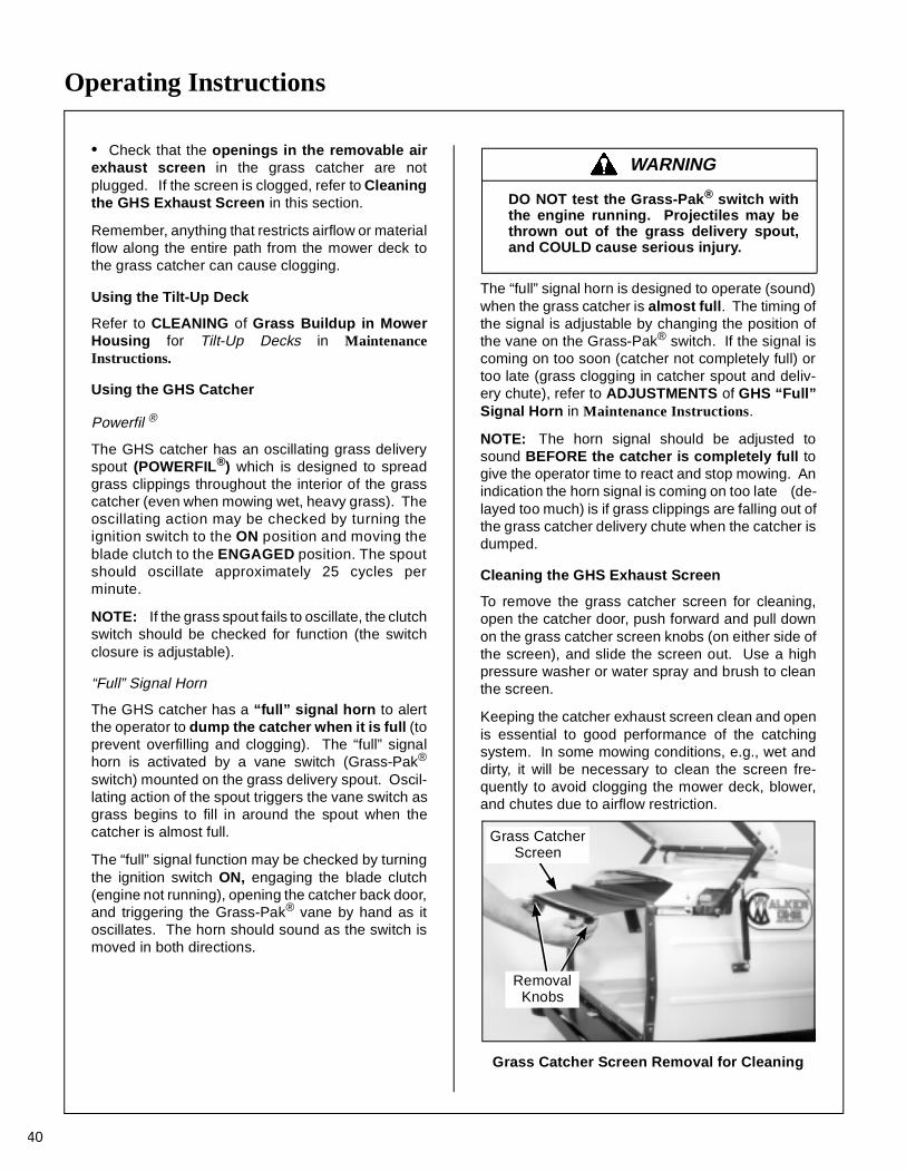
Operating Instructions
40
• Check that the openings in the removable airexhaust screen in the grass catcher are notplugged. If the screen is clogged, refer to Cleaningthe GHS Exhaust Screen in this section.
Remember, anything that restricts airflow or materialflow along the entire path from the mower deck tothe grass catcher can cause clogging.
Using the Tilt-Up Deck
Refer to CLEANING of Grass Buildup in MowerHousing for Tilt-Up Decks in MaintenanceInstructions.
Using the GHS Catcher
Powerfil ®
The GHS catcher has an oscillating grass deliveryspout (POWERFIL®) which is designed to spreadgrass clippings throughout the interior of the grasscatcher (even when mowing wet, heavy grass). Theoscillating action may be checked by turning theignition switch to the ON position and moving theblade clutch to the ENGAGED position. The spoutshould oscillate approximately 25 cycles perminute.
NOTE: If the grass spout fails to oscillate, the clutchswitch should be checked for function (the switchclosure is adjustable).
“Full” Signal Horn
The GHS catcher has a “full” signal horn to alertthe operator to dump the catcher when it is full (toprevent overfilling and clogging). The “full” signalhorn is activated by a vane switch (Grass-Pak®
switch) mounted on the grass delivery spout. Oscil-lating action of the spout triggers the vane switch asgrass begins to fill in around the spout when thecatcher is almost full.
The “full” signal function may be checked by turningthe ignition switch ON, engaging the blade clutch(engine not running), opening the catcher back door,and triggering the Grass-Pak® vane by hand as itoscillates. The horn should sound as the switch ismoved in both directions.
The “full” signal horn is designed to operate (sound)when the grass catcher is almost full. The timing ofthe signal is adjustable by changing the position ofthe vane on the Grass-Pak® switch. If the signal iscoming on too soon (catcher not completely full) ortoo late (grass clogging in catcher spout and deliv-ery chute), refer to ADJUSTMENTS of GHS “Full”Signal Horn in Maintenance Instructions.
NOTE: The horn signal should be adjusted tosound BEFORE the catcher is completely full togive the operator time to react and stop mowing. Anindication the horn signal is coming on too late (de-layed too much) is if grass clippings are falling out ofthe grass catcher delivery chute when the catcher isdumped.
Cleaning the GHS Exhaust Screen
To remove the grass catcher screen for cleaning,open the catcher door, push forward and pull downon the grass catcher screen knobs (on either side ofthe screen), and slide the screen out. Use a highpressure washer or water spray and brush to cleanthe screen.
Keeping the catcher exhaust screen clean and openis essential to good performance of the catchingsystem. In some mowing conditions, e.g., wet anddirty, it will be necessary to clean the screen fre-quently to avoid clogging the mower deck, blower,and chutes due to airflow restriction.
Grass Catcher Screen Removal for Cleaning
WARNING
DO NOT test the Grass-Pak ® switch withthe engine running. Projectiles may bethrown out of the grass delivery spout,and COULD cause serious injury.
Grass CatcherScreen
RemovalKnobs
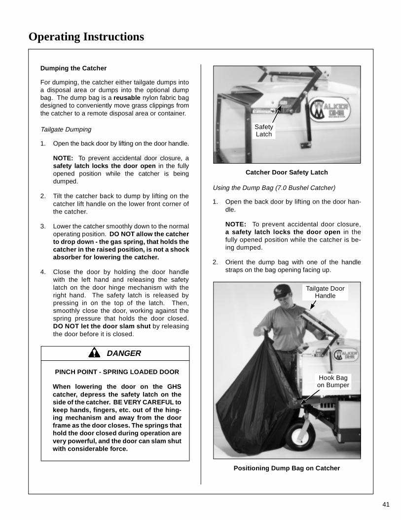
Operating Instructions
41
Dumping the Catcher
For dumping, the catcher either tailgate dumps intoa disposal area or dumps into the optional dumpbag. The dump bag is a reusable nylon fabric bagdesigned to conveniently move grass clippings fromthe catcher to a remote disposal area or container.
Tailgate Dumping
1. Open the back door by lifting on the door handle.
NOTE: To prevent accidental door closure, asafety latch locks the door open in the fullyopened position while the catcher is beingdumped.
2. Tilt the catcher back to dump by lifting on thecatcher lift handle on the lower front corner ofthe catcher.
3. Lower the catcher smoothly down to the normaloperating position. DO NOT allow the catcherto drop down - the gas spring, that holds thecatcher in the raised position, is not a shockabsorber for lowering the catcher.
4. Close the door by holding the door handlewith the left hand and releasing the safetylatch on the door hinge mechanism with theright hand. The safety latch is released bypressing in on the top of the latch. Then,smoothly close the door, working against thespring pressure that holds the door closed.DO NOT let the door slam shut by releasingthe door before it is closed.
Catcher Door Safety Latch
Using the Dump Bag (7.0 Bushel Catcher)
1. Open the back door by lifting on the door han-dle.
NOTE: To prevent accidental door closure,a safety latch locks the door open in thefully opened position while the catcher is be-ing dumped.
2. Orient the dump bag with one of the handlestraps on the bag opening facing up.
Positioning Dump Bag on Catcher
DANGER
PINCH POINT - SPRING LOADED DOOR
When lowering the door on the GHScatcher, depress the safety latch on theside of the catcher. BE VERY CAREFUL tokeep hands, fingers, etc. out of the hing-ing mechanism and away from the doorframe as the door closes. The springs thathold the door closed during operation arevery powerful, and the door can slam shutwith considerable force.
SafetyLatch
Hook Bagon Bumper
Tailgate DoorHandle
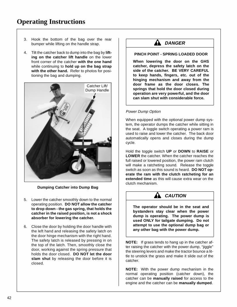
Operating Instructions
42
3. Hook the bottom of the bag over the rearbumper while lifting on the handle strap.
4. Tilt the catcher back to dump into the bag by lift-ing on the catcher lift handle on the lowerfront corner of the catcher with the one handwhile continuing to hold up on the bag strapwith the other hand. Refer to photos for posi-tioning the bag and dumping.
Dumping Catcher into Dump Bag
5. Lower the catcher smoothly down to the normaloperating position. DO NOT allow the catcherto drop down - the gas spring, that holds thecatcher in the raised position, is not a shockabsorber for lowering the catcher.
6. Close the door by holding the door handle withthe left hand and releasing the safety latch onthe door hinge mechanism with the right hand.The safety latch is released by pressing in onthe top of the latch. Then, smoothly close thedoor, working against the spring pressure thatholds the door closed. DO NOT let the doorslam shut by releasing the door before it isclosed.
Power Dump Option
When equipped with the optional power dump sys-tem, the operator dumps the catcher while sitting inthe seat. A toggle switch operating a power ram isused to raise and lower the catcher. The back doorautomatically opens and closes during the dumpcycle.
Hold the toggle switch UP or DOWN to RAISE orLOWER the catcher. When the catcher reaches thefull raised or lowered position, the power ram clutchwill make a ratcheting sound. Release the toggleswitch as soon as this sound is heard. DO NOT op-erate the ram with the clutch ratcheting for anextended time as this will cause extra wear on theclutch mechanism.
NOTE: If grass tends to hang up in the catcher af-ter raising the catcher with the power dump, “jiggle”the steering levers and make the tractor bounce a lit-tle to unstick the grass and make it slide out of thecatcher.
NOTE: With the power dump mechanism in thenormal operating position (catcher down), thecatcher can be manually raised for access to theengine and the catcher can be manually dumped.
Catcher Lift/Dump Handle
DANGER
PINCH POINT - SPRING LOADED DOOR
When lowering the door on the GHScatcher, depress the safety latch on theside of the catcher. BE VERY CAREFULto keep hands, fingers, etc. out of thehinging mechanism and away from thedoor frame as the door closes. Thesprings that hold the door closed duringoperation are very powerful, and the doorcan slam shut with considerable force.
CAUTION
The operator should be in the seat andbystanders stay clear when the powerdump is operating. The power dump isused ONLY for tailgate dumping. Do notattempt to use the optional dump bag orany other bag with the power dump.
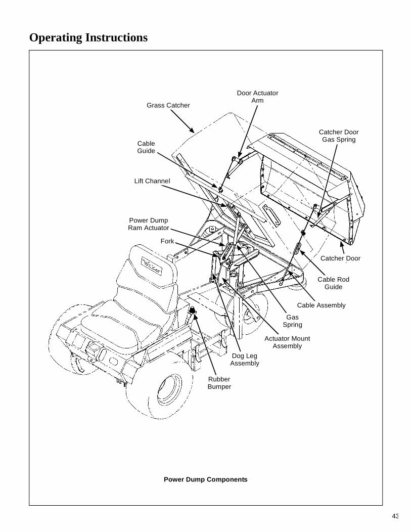
Operating Instructions
43
Power Dump Components
Grass Catcher
CableGuide
Catcher DoorGas Spring
Catcher Door
Cable RodGuide
Cable Assembly
Actuator MountAssembly
Dog LegAssembly
Fork
Lift Channel
Door ActuatorArm
GasSpring
RubberBumper
Power DumpRam Actuator

Maintenance Instructions
44
MAINTENANCE SCHEDULE CHART - RECOMMENDED SERVICE INTERVALS - MODEL MT
Service Item Daily25
Hours100
Hours200
Hours YearlyEvery 2Years
Ref.Page
Check Engine Crankcase Oil Level x 46Check/Clean Engine Air Cooling System* x 57Check Security of Air Filtration Components x 60Check Air Filter Restriction Gauge x 54Clean Grass Buildup Under Deck x 58Clean GHS Exhaust Screen* x 40Clean GHS Blower* x 59Service Mower Blades x 61Check Functions of Instrument Panel and Warning Horn x 22
Lubricate Grease Fittings and Oil Points* x 47Check PTO Gearbox Oil Level** x 51Check Battery Electrolyte Level x 60Check Hydrostatic Transmission Fluid x 52Check Tire Pressure x 61Check Drive Belts (Jackshaft, Engine PTO, GHS Blower, Ground Drive) x 62
Check Gearbox Oil Seals x 63Check Turbine Precleaner* x 54Check/Clean Primary Air Filter Element ∆ x 54Change Engine Crankcase Oil ∆∆ x 46Check/Adjust Blade Clutch (PTO)/Brake Action x 74
Check Oil Level in Gear Axle x 51Clean Hydrostatic Transmission Cooling Fins x 60Clean Engine Cooling Fins x 57Check/Regap Spark Plugs x 63Change Engine Oil Filter x 46Check Fuel Lines and Clamps x 63Check/Clean Secondary Air Filter Element and Foam Precleaner ∆ x 56
Replace Primary Air Filter Element and Vacuator™ Valve ∆ x 54
Replace Fuel Filter x 69Service Battery x 60Check/Adjust FSC Friction Lock x 79Service Solenoid Shift Starter x 63Change Gear Axle Oil ∆∆∆ x 51Change Hydrostatic Transmission Fluid ∆∆∆ x 52Replace Fuel Lines and Clamps x 63
∗ More often in extremely dusty or dirty conditions (refer to notes about air cleaner element inIMPORTANT TIPS FOR CARE OF KOHLER ENGINE)
∗∗ Change PTO gearbox oil after first 100 hours of operation (break-in period)∆ Primary air cleaner is remote mounted Donaldson Radialseal™ unit, secondary air cleaner is
standard Kohler engine mounted unit, replace primary filter every year or after 6 cleanings∆∆ Change engine oil and filter after first 5 hours of operation of a new engine (break-in period)
∆∆∆ Change every 2 years or 1000 hours
CAUTION
Maintenance procedures requiring special training ortools should be performed by a trained technician.
Maintenance Instructions KOHLER TIPS
45
IMPORTANT TIPS FOR CARE OF THE KOHLER ENGINE
Fuel System
• Fuel must be clean - free from water, dirt, and or-ganic material.
• Change fuel filter on a regular basis and whencontamination is suspected or found in the fuel.
Starting/Stopping
• For starting in cold weather [below 40° F (4° C)],use the optional cold start lever to release the hydro-static transmissions from the starter cranking load.
• Start engine with the throttle advanced off idle(1/4 to 1/2 throttle). This will aid starting, especiallyin cold weather.
• Keep the battery fully charged.
• Match crankcase oil viscosity to the ambient tem-perature, allowing the engine to crank faster andstart easier.
• Use fast idle for stopping engine to avoid run-onor backfiring.
Cooling System
• Keep engine air intake screen and cylinder headfins free of grass clippings, chaff, and dirt. Inspectintake screen and cooling fins for cleanliness and nodamage.
• Periodically remove two access panels in the en-gine shroud to inspect and clean cylinder head cool-ing fins.
• Check performance of the cooling system bystarting the engine, holding a hand adjacent to thecylinder head, and feeling the cooling airflow.
• Operate the engine at full speed when mowing.This allows the engine to produce full horsepowerand move more cooling air through the engine cool-ing fins.
Air Cleaner System
• Use only Kohler and Donaldson air cleaner ele-ments. Aftermarket elements may not seal in the aircleaner housing, allowing dirt to enter the engine. Al-so, aftermarket filters often skimp on the filtrationmedia and require more frequent cleaning and re-placement (see following instructions).
• Use the air flow restriction gauge to indicate theneed to service the primary air filter.
• Do frequently check the Turbine Precleaner forfree movement of the internal fan.
• DO NOT overservice or frequently “disturb” ei-ther the primary or the secondary air filter. A dirtyair filter actually cleans better than a new one.Changing and cleaning the air filter too often can ac-tually reduce filter efficiency and increase the oppor-tunity for traces of dust to enter the engine. For theprimary filter, wait until the element really needs ser-vicing as indicated by the air flow restriction gauge.The secondary air filter should be serviced yearly orif there are indications that the primary filter hasfailed.
• When the primary air filter element is removed orreplaced, make sure all dust is cleaned out of theair cleaner housing and hose. Use a damp clothand wipe the interior of the canister and hose clean(a little dirt left here will be sucked into the engineand reduce engine life). When the filter is rein-stalled, make sure the element is held tight andstraight in the canister for proper seating andsealing.
• Periodically check the air intake hose for cuts,nicks, etc., and the hose clamps for tightness.
Oil
• Use only multi-viscosity oils as specified with theviscosity matching ambient temperatures for the en-gine operating conditions. This will aid starting incold weather and assure proper lubrication in hotweather.
• Use only Kohler oil filters. Aftermarket filtersmay not seal properly and/or have the incorrectpressure relief valve for proper lubrication.
DANGER
Make sure to keep hands clear of exhaustpipe, muffler, and moving parts whenchecking airflow.
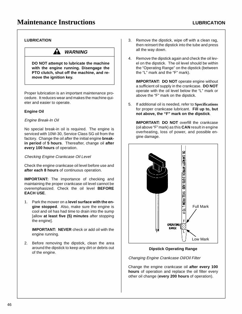
Maintenance Instructions LUBRICATION
46
LUBRICATION
Proper lubrication is an important maintenance pro-cedure. It reduces wear and makes the machine qui-eter and easier to operate.
Engine Oil
Engine Break-In Oil
No special break-in oil is required. The engine isserviced with 10W-30, Service Class SG oil from thefactory. Change the oil after the initial engine break-in period of 5 hours. Thereafter, change oil afterevery 100 hours of operation.
Checking Engine Crankcase Oil Level
Check the engine crankcase oil level before use andafter each 8 hours of continuous operation.
IMPORTANT: The importance of checking andmaintaining the proper crankcase oil level cannot beoveremphasized. Check the oil level BEFOREEACH USE.
1. Park the mower on a level surface with the en-gine stopped. Also, make sure the engine iscool and oil has had time to drain into the sump[allow at least five (5) minutes after stoppingthe engine].
IMPORTANT: NEVER check or add oil with theengine running.
2. Before removing the dipstick, clean the areaaround the dipstick to keep any dirt or debris outof the engine.
3. Remove the dipstick, wipe off with a clean rag,then reinsert the dipstick into the tube and pressall the way down.
4. Remove the dipstick again and check the oil lev-el on the dipstick. The oil level should be withinthe “Operating Range” on the dipstick (betweenthe “L” mark and the “F” mark).
IMPORTANT: DO NOT operate engine withouta sufficient oil supply in the crankcase. DO NOToperate with the oil level below the “L” mark orabove the “F” mark on the dipstick.
5. If additional oil is needed, refer to Specificationsfor proper crankcase lubricant. Fill up to, butnot above, the “F” mark on the dipstick .
IMPORTANT: DO NOT overfill the crankcase(oil above “F” mark) as this CAN result in engineoverheating, loss of power, and possible en-gine damage.
Dipstick Operating Range
Changing Engine Crankcase Oil/Oil Filter
Change the engine crankcase oil after every 100hours of operation and replace the oil filter everyother oil change (every 200 hours of operation).
WARNING
DO NOT attempt to lubricate the machinewith the engine running. Disengage thePTO clutch, shut off the machine, and re-move the ignition key.
Full Mark
Low Mark
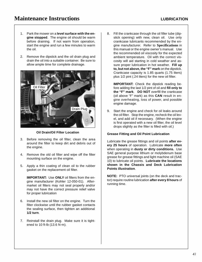
Maintenance Instructions LUBRICATION
47
1. Park the mower on a level surface with the en-gine stopped. The engine oil should be warmbefore draining. If not warm from operation,start the engine and run a few minutes to warmthe oil.
2. Remove the dipstick and the oil drain plug anddrain the oil into a suitable container. Be sure toallow ample time for complete drainage.
Oil Drain/Oil Filter Location
3. Before removing the oil filter, clean the areaaround the filter to keep dirt and debris out ofthe engine.
4. Remove the old oil filter and wipe off the filtermounting surface on the engine.
5. Apply a thin coating of clean oil to the rubbergasket on the replacement oil filter.
IMPORTANT: Use ONLY oil filters from the en-gine manufacturer (Kohler 12-050-01). After-market oil filters may not seal properly and/ormay not have the correct pressure relief valvefor proper lubrication
6. Install the new oil filter on the engine. Turn thefilter clockwise until the rubber gasket contactsthe sealing surface, then tighten an additional1/2 turn.
7. Reinstall the drain plug. Make sure it is tight-ened to 10 ft-lb (13.6 N·m).
8. Fill the crankcase through the oil filler tube (dip-stick opening) with new, clean oil. Use onlycrankcase lubricants recommended by the en-gine manufacturer. Refer to Specifications inthis manual or the engine owner’s manual. Usethe recommended oil viscosity for the expectedambient temperature. Oil with the correct vis-cosity will aid starting in cold weather and as-sure proper lubrication in hot weather. Fill upto, but not above, the “F” mark on the dipstick.Crankcase capacity is 1.85 quarts (1.75 liters)plus 1/2 pint (.24 liters) for the new oil filter.
IMPORTANT: Check the dipstick reading be-fore adding the last 1/2 pint of oil and fill only tothe “F” mark . DO NOT overfill the crankcase(oil above “F” mark) as this CAN result in en-gine overheating, loss of power, and possibleengine damage.
9. Start the engine and check for oil leaks aroundthe oil filter. Stop the engine, recheck the oil lev-el, and add oil if necessary. (When the engineis first operated with a new oil filter, the oil leveldrops slightly as the filter is filled with oil.)
Grease Fitting and Oil Point Lubrication
Lubricate the grease fittings and oil points after ev-ery 25 hours of operation. Lubricate more oftenwhen operating in dusty or dirty conditions. UseSAE general purpose lithium or molybdenum basegrease for grease fittings and light machine oil (SAE10) to lubricate oil points. Lubricate the locationsshown in the Chassis and Deck LubricationPoints illustration.
NOTE: PTO universal joints (on the deck and trac-tor) require routine lubrication after every 8 hours ofrunning time.
Oil Filter
Drain Plug
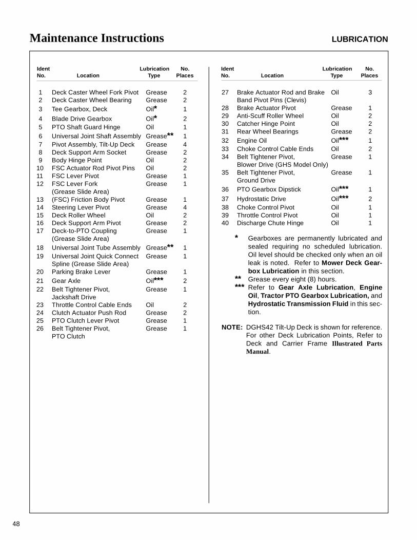
Maintenance Instructions LUBRICATION
48
Ident Lubrication No.No. Location Type Places
Ident Lubrication No.No. Location Type Places
1 Deck Caster Wheel Fork Pivot Grease 22 Deck Caster Wheel Bearing Grease 23 Tee Gearbox, Deck Oil* 1
4 Blade Drive Gearbox Oil* 25 PTO Shaft Guard Hinge Oil 16 Universal Joint Shaft Assembly Grease** 17 Pivot Assembly, Tilt-Up Deck Grease 48 Deck Support Arm Socket Grease 29 Body Hinge Point Oil 2
10 FSC Actuator Rod Pivot Pins Oil 211 FSC Lever Pivot Grease 112 FSC Lever Fork Grease 1
(Grease Slide Area)13 (FSC) Friction Body Pivot Grease 114 Steering Lever Pivot Grease 415 Deck Roller Wheel Oil 216 Deck Support Arm Pivot Grease 217 Deck-to-PTO Coupling Grease 1
(Grease Slide Area)18 Universal Joint Tube Assembly Grease** 119 Universal Joint Quick Connect Grease 1
Spline (Grease Slide Area)20 Parking Brake Lever Grease 121 Gear Axle Oil*** 222 Belt Tightener Pivot, Grease 1
Jackshaft Drive23 Throttle Control Cable Ends Oil 224 Clutch Actuator Push Rod Grease 225 PTO Clutch Lever Pivot Grease 126 Belt Tightener Pivot, Grease 1
PTO Clutch
27 Brake Actuator Rod and Brake Oil 3Band Pivot Pins (Clevis)
28 Brake Actuator Pivot Grease 129 Anti-Scuff Roller Wheel Oil 230 Catcher Hinge Point Oil 231 Rear Wheel Bearings Grease 232 Engine Oil Oil*** 133 Choke Control Cable Ends Oil 234 Belt Tightener Pivot, Grease 1
Blower Drive (GHS Model Only)35 Belt Tightener Pivot, Grease 1
Ground Drive36 PTO Gearbox Dipstick Oil*** 1
37 Hydrostatic Drive Oil*** 238 Choke Control Pivot Oil 139 Throttle Control Pivot Oil 140 Discharge Chute Hinge Oil 1
* Gearboxes are permanently lubricated andsealed requiring no scheduled lubrication.Oil level should be checked only when an oilleak is noted. Refer to Mower Deck Gear-box Lubrication in this section.
** Grease every eight (8) hours.*** Refer to Gear Axle Lubrication, Engine
Oil, Tractor PTO Gearbox Lubrication, andHydrostatic Transmission Fluid in this sec-tion.
NOTE: DGHS42 Tilt-Up Deck is shown for reference.For other Deck Lubrication Points, Refer toDeck and Carrier Frame Illustrated PartsManual.
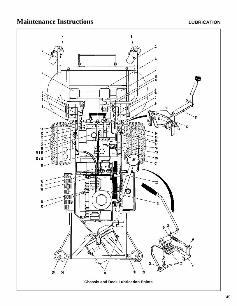
Maintenance Instructions LUBRICATION
49
Chassis and Deck Lubrication Points
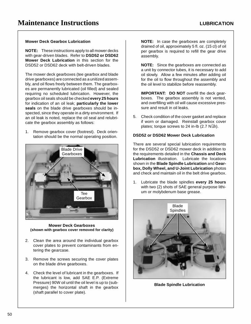
Maintenance Instructions LUBRICATION
50
Mower Deck Gearbox Lubrication
NOTE: These instructions apply to all mower deckswith gear-driven blades. Refer to DSD52 or DSD62Mower Deck Lubrication in this section for theDSD52 or DSD62 deck with belt-driven blades.
The mower deck gearboxes (tee gearbox and bladedrive gearboxes) are connected as a unitized assem-bly, and oil flows freely between them. The gearbox-es are permanently lubricated (oil filled) and sealedrequiring no scheduled lubrication. However, thegearbox oil seals should be checked every 25 hoursfor indication of an oil leak; particularly the lowerseals on the blade drive gearboxes should be in-spected, since they operate in a dirty environment. Ifan oil leak is noted, replace the oil seal and relubri-cate the gearbox assembly as follows:
1. Remove gearbox cover (footrest). Deck orien-tation should be the normal operating position.
Mower Deck Gearboxes(shown with gearbox cover removed for clarity)
2. Clean the area around the individual gearboxcover plates to prevent contaminants from en-tering the gearcase.
3. Remove the screws securing the cover plateson the blade drive gearboxes.
4. Check the level of lubricant in the gearboxes. Ifthe lubricant is low, add SAE E.P. (ExtremePressure) 90W oil until the oil level is up to (sub-merges) the horizontal shaft in the gearbox(shaft parallel to cover plate).
NOTE: In case the gearboxes are completelydrained of oil, approximately 5 fl. oz. (15 cl) of oilper gearbox is required to refill the gear driveassembly.
NOTE: Since the gearboxes are connected asa unit by connector tubes, it is necessary to addoil slowly. Allow a few minutes after adding oilfor the oil to flow throughout the assembly andthe oil level to stabilize before reassembly.
IMPORTANT: DO NOT overfill the deck gear-boxes. The gearbox assembly is not vented,and overfilling with oil will cause excessive pres-sure and result in oil leaks.
5. Check condition of the cover gasket and replaceif worn or damaged. Reinstall gearbox coverplates; torque screws to 24 in-lb (2.7 N⋅m).
DSD52 or DSD62 Mower Deck Lubrication
There are several special lubrication requirementsfor the DSD52 or DSD62 mower deck in addition tothe requirements detailed in the Chassis and DeckLubrication illustration. Lubricate the locationsshown in the Blade Spindle Lubrication and Gear-box, Dolly Wheel, and U-Joint Lubrication photosand check and maintain oil in the belt drive gearbox.
1. Lubricate the blade spindles every 25 hourswith two (2) shots of SAE general purpose lithi-um or molybdenum base grease.
Blade Spindle Lubrication
Blade DriveGearboxes
TeeGearbox
BladeSpindles
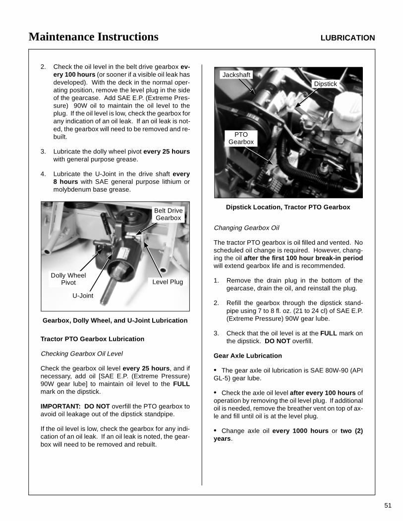
Maintenance Instructions LUBRICATION
51
2. Check the oil level in the belt drive gearbox ev-ery 100 hours (or sooner if a visible oil leak hasdeveloped). With the deck in the normal oper-ating position, remove the level plug in the sideof the gearcase. Add SAE E.P. (Extreme Pres-sure) 90W oil to maintain the oil level to theplug. If the oil level is low, check the gearbox forany indication of an oil leak. If an oil leak is not-ed, the gearbox will need to be removed and re-built.
3. Lubricate the dolly wheel pivot every 25 hourswith general purpose grease.
4. Lubricate the U-Joint in the drive shaft every8 hours with SAE general purpose lithium ormolybdenum base grease.
Gearbox, Dolly Wheel, and U-Joint Lubrication
Tractor PTO Gearbox Lubrication
Checking Gearbox Oil Level
Check the gearbox oil level every 25 hours, and ifnecessary, add oil [SAE E.P. (Extreme Pressure)90W gear lube] to maintain oil level to the FULLmark on the dipstick.
IMPORTANT: DO NOT overfill the PTO gearbox toavoid oil leakage out of the dipstick standpipe.
If the oil level is low, check the gearbox for any indi-cation of an oil leak. If an oil leak is noted, the gear-box will need to be removed and rebuilt.
Dipstick Location, Tractor PTO Gearbox
Changing Gearbox Oil
The tractor PTO gearbox is oil filled and vented. Noscheduled oil change is required. However, chang-ing the oil after the first 100 hour break-in periodwill extend gearbox life and is recommended.
1. Remove the drain plug in the bottom of thegearcase, drain the oil, and reinstall the plug.
2. Refill the gearbox through the dipstick stand-pipe using 7 to 8 fl. oz. (21 to 24 cl) of SAE E.P.(Extreme Pressure) 90W gear lube.
3. Check that the oil level is at the FULL mark onthe dipstick. DO NOT overfill.
Gear Axle Lubrication
• The gear axle oil lubrication is SAE 80W-90 (APIGL-5) gear lube.
• Check the axle oil level after every 100 hours ofoperation by removing the oil level plug. If additionaloil is needed, remove the breather vent on top of ax-le and fill until oil is at the level plug.
• Change axle oil every 1000 hours or two (2)years.
Dolly WheelPivot
U-Joint
Level Plug
Belt DriveGearbox
PTOGearbox
JackshaftDipstick
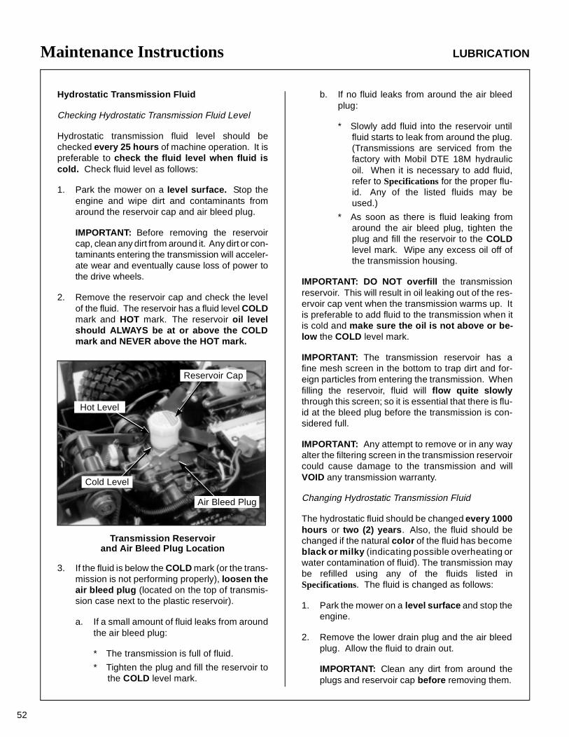
Maintenance Instructions LUBRICATION
52
Hydrostatic Transmission Fluid
Checking Hydrostatic Transmission Fluid Level
Hydrostatic transmission fluid level should bechecked every 25 hours of machine operation. It ispreferable to check the fluid level when fluid iscold. Check fluid level as follows:
1. Park the mower on a level surface. Stop theengine and wipe dirt and contaminants fromaround the reservoir cap and air bleed plug.
IMPORTANT: Before removing the reservoircap, clean any dirt from around it. Any dirt or con-taminants entering the transmission will acceler-ate wear and eventually cause loss of power tothe drive wheels.
2. Remove the reservoir cap and check the levelof the fluid. The reservoir has a fluid level COLDmark and HOT mark. The reservoir oil levelshould ALWAYS be at or above the COLDmark and NEVER above the HOT mark.
Transmission Reservoirand Air Bleed Plug Location
3. If the fluid is below the COLD mark (or the trans-mission is not performing properly), loosen theair bleed plug (located on the top of transmis-sion case next to the plastic reservoir).
a. If a small amount of fluid leaks from aroundthe air bleed plug:
* The transmission is full of fluid.
* Tighten the plug and fill the reservoir tothe COLD level mark.
b. If no fluid leaks from around the air bleedplug:
* Slowly add fluid into the reservoir untilfluid starts to leak from around the plug.(Transmissions are serviced from thefactory with Mobil DTE 18M hydraulicoil. When it is necessary to add fluid,refer to Specifications for the proper flu-id. Any of the listed fluids may beused.)
* As soon as there is fluid leaking fromaround the air bleed plug, tighten theplug and fill the reservoir to the COLDlevel mark. Wipe any excess oil off ofthe transmission housing.
IMPORTANT: DO NOT overfill the transmissionreservoir. This will result in oil leaking out of the res-ervoir cap vent when the transmission warms up. Itis preferable to add fluid to the transmission when itis cold and make sure the oil is not above or be-low the COLD level mark.
IMPORTANT: The transmission reservoir has afine mesh screen in the bottom to trap dirt and for-eign particles from entering the transmission. Whenfilling the reservoir, fluid will flow quite slowlythrough this screen; so it is essential that there is flu-id at the bleed plug before the transmission is con-sidered full.
IMPORTANT: Any attempt to remove or in any wayalter the filtering screen in the transmission reservoircould cause damage to the transmission and willVOID any transmission warranty.
Changing Hydrostatic Transmission Fluid
The hydrostatic fluid should be changed every 1000hours or two (2) years. Also, the fluid should bechanged if the natural color of the fluid has becomeblack or milky (indicating possible overheating orwater contamination of fluid). The transmission maybe refilled using any of the fluids listed inSpecifications. The fluid is changed as follows:
1. Park the mower on a level surface and stop theengine.
2. Remove the lower drain plug and the air bleedplug. Allow the fluid to drain out.
IMPORTANT: Clean any dirt from around theplugs and reservoir cap before removing them.
Cold Level
Reservoir Cap
Hot Level
Air Bleed Plug
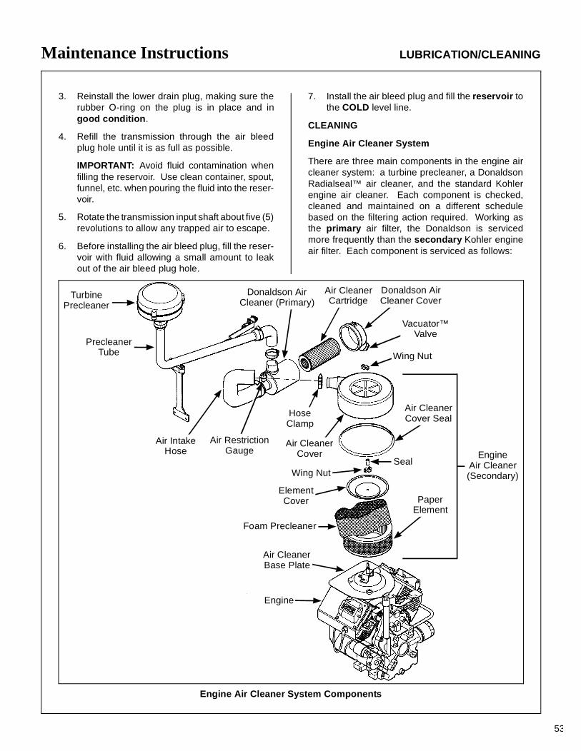
Maintenance Instructions LUBRICATION/CLEANING
53
3. Reinstall the lower drain plug, making sure therubber O-ring on the plug is in place and ingood condition.
4. Refill the transmission through the air bleedplug hole until it is as full as possible.
IMPORTANT: Avoid fluid contamination whenfilling the reservoir. Use clean container, spout,funnel, etc. when pouring the fluid into the reser-voir.
5. Rotate the transmission input shaft about five (5)revolutions to allow any trapped air to escape.
6. Before installing the air bleed plug, fill the reser-voir with fluid allowing a small amount to leakout of the air bleed plug hole.
7. Install the air bleed plug and fill the reservoir tothe COLD level line.
CLEANING
Engine Air Cleaner System
There are three main components in the engine aircleaner system: a turbine precleaner, a DonaldsonRadialseal™ air cleaner, and the standard Kohlerengine air cleaner. Each component is checked,cleaned and maintained on a different schedulebased on the filtering action required. Working asthe primary air filter, the Donaldson is servicedmore frequently than the secondary Kohler engineair filter. Each component is serviced as follows:
TurbinePrecleaner
PrecleanerTube
HoseClamp
Air CleanerCover
Air IntakeHose
Engine
Air CleanerBase Plate
Air RestrictionGauge
Donaldson AirCleaner (Primary)
Air CleanerCartridge
Donaldson AirCleaner Cover
Vacuator™Valve
Wing Nut
Air CleanerCover Seal
Seal
ElementCover
Wing Nut
EngineAir Cleaner(Secondary)
PaperElement
Foam Precleaner
Engine Air Cleaner System Components
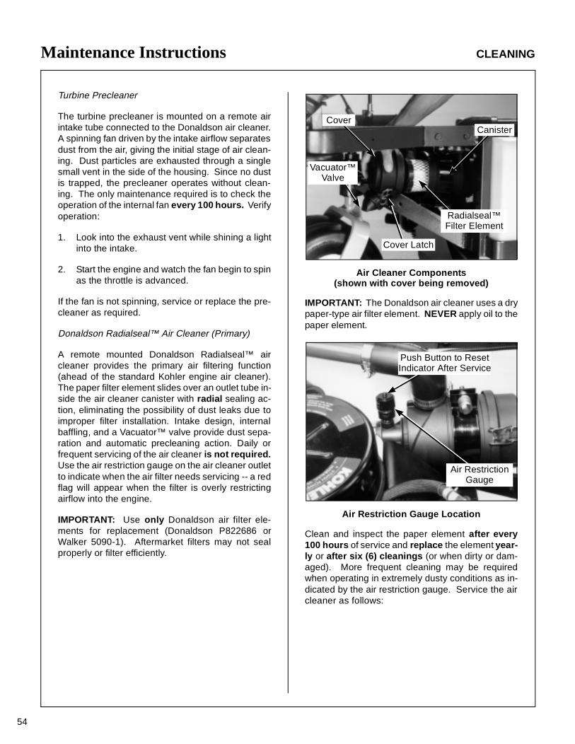
Maintenance Instructions CLEANING
54
Turbine Precleaner
The turbine precleaner is mounted on a remote airintake tube connected to the Donaldson air cleaner.A spinning fan driven by the intake airflow separatesdust from the air, giving the initial stage of air clean-ing. Dust particles are exhausted through a singlesmall vent in the side of the housing. Since no dustis trapped, the precleaner operates without clean-ing. The only maintenance required is to check theoperation of the internal fan every 100 hours. Verifyoperation:
1. Look into the exhaust vent while shining a lightinto the intake.
2. Start the engine and watch the fan begin to spinas the throttle is advanced.
If the fan is not spinning, service or replace the pre-cleaner as required.
Donaldson Radialseal™ Air Cleaner (Primary)
A remote mounted Donaldson Radialseal™ aircleaner provides the primary air filtering function(ahead of the standard Kohler engine air cleaner).The paper filter element slides over an outlet tube in-side the air cleaner canister with radial sealing ac-tion, eliminating the possibility of dust leaks due toimproper filter installation. Intake design, internalbaffling, and a Vacuator™ valve provide dust sepa-ration and automatic precleaning action. Daily orfrequent servicing of the air cleaner is not required.Use the air restriction gauge on the air cleaner outletto indicate when the air filter needs servicing -- a redflag will appear when the filter is overly restrictingairflow into the engine.
IMPORTANT: Use only Donaldson air filter ele-ments for replacement (Donaldson P822686 orWalker 5090-1). Aftermarket filters may not sealproperly or filter efficiently.
Air Cleaner Components(shown with cover being removed)
IMPORTANT: The Donaldson air cleaner uses a drypaper-type air filter element. NEVER apply oil to thepaper element.
Air Restriction Gauge Location
Clean and inspect the paper element after every100 hours of service and replace the element year-ly or after six (6) cleanings (or when dirty or dam-aged). More frequent cleaning may be requiredwhen operating in extremely dusty conditions as in-dicated by the air restriction gauge. Service the aircleaner as follows:
CanisterCover
Vacuator™Valve
Cover Latch
Radialseal™Filter Element
Push Button to ResetIndicator After Service
Air RestrictionGauge
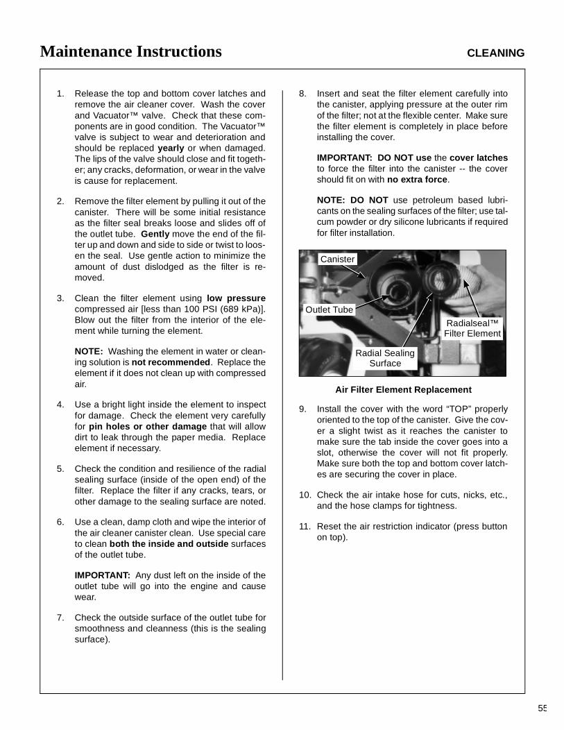
Maintenance Instructions CLEANING
55
1. Release the top and bottom cover latches andremove the air cleaner cover. Wash the coverand Vacuator™ valve. Check that these com-ponents are in good condition. The Vacuator™valve is subject to wear and deterioration andshould be replaced yearly or when damaged.The lips of the valve should close and fit togeth-er; any cracks, deformation, or wear in the valveis cause for replacement.
2. Remove the filter element by pulling it out of thecanister. There will be some initial resistanceas the filter seal breaks loose and slides off ofthe outlet tube. Gently move the end of the fil-ter up and down and side to side or twist to loos-en the seal. Use gentle action to minimize theamount of dust dislodged as the filter is re-moved.
3. Clean the filter element using low pressurecompressed air [less than 100 PSI (689 kPa)].Blow out the filter from the interior of the ele-ment while turning the element.
NOTE: Washing the element in water or clean-ing solution is not recommended. Replace theelement if it does not clean up with compressedair.
4. Use a bright light inside the element to inspectfor damage. Check the element very carefullyfor pin holes or other damage that will allowdirt to leak through the paper media. Replaceelement if necessary.
5. Check the condition and resilience of the radialsealing surface (inside of the open end) of thefilter. Replace the filter if any cracks, tears, orother damage to the sealing surface are noted.
6. Use a clean, damp cloth and wipe the interior ofthe air cleaner canister clean. Use special careto clean both the inside and outside surfacesof the outlet tube.
IMPORTANT: Any dust left on the inside of theoutlet tube will go into the engine and causewear.
7. Check the outside surface of the outlet tube forsmoothness and cleanness (this is the sealingsurface).
8. Insert and seat the filter element carefully intothe canister, applying pressure at the outer rimof the filter; not at the flexible center. Make surethe filter element is completely in place beforeinstalling the cover.
IMPORTANT: DO NOT use the cover latchesto force the filter into the canister -- the covershould fit on with no extra force.
NOTE: DO NOT use petroleum based lubri-cants on the sealing surfaces of the filter; use tal-cum powder or dry silicone lubricants if requiredfor filter installation.
Air Filter Element Replacement
9. Install the cover with the word “TOP” properlyoriented to the top of the canister. Give the cov-er a slight twist as it reaches the canister tomake sure the tab inside the cover goes into aslot, otherwise the cover will not fit properly.Make sure both the top and bottom cover latch-es are securing the cover in place.
10. Check the air intake hose for cuts, nicks, etc.,and the hose clamps for tightness.
11. Reset the air restriction indicator (press buttonon top).
Canister
Radialseal™Filter Element
Radial SealingSurface
Outlet Tube
Maintenance Instructions CLEANING
56
Kohler Air Cleaner (Secondary)
NOTE: The Kohler Air Cleaner should only be ser-viced more often than a yearly interval if there areindications that the Donaldson Radialseal (prima-ry) has failed.
• Foam Precleaner
An oiled, foam precleaner surrounds the paper ele-ment of the Kohler engine air cleaner system. Cleanand re-oil the foam precleaner yearly or more oftenin dusty or dirty conditions.
1. Unscrew the air cleaner cover mounting nut andremove the air cleaner cover.
2. Remove the foam precleaner by sliding it off thepaper element.
IMPORTANT: Replace the foam precleaner ifnecessary. Use ONLY Kohler replacement part#24-083-02.
3. Wash the foam precleaner in warm water withdetergent. Rinse thoroughly and squeeze outexcess water (do not wring). Allow the preclean-er to air dry.
4. Saturate the foam with clean engine oil.Squeeze to distribute and remove excess oil.
5. Reinstall the precleaner by sliding it over the pa-per element.
6. Reinstall the air cleaner cover and mounting nut.
• Paper Element
The Kohler engine uses a dry, high density paper airfilter element. Check the element (located under thefoam precleaner) yearly or more often in dusty ordirty conditions. Replace the element if it is dirty,bent, or damaged.
IMPORTANT: Use ONLY Kohler part #47-083-03.Aftermarket filters may not seal properly or filter ef-ficiently.
IMPORTANT: Kohler does not recommend clean-ing the paper element and reinstalling. DO NOTwash the element or use pressurized air to clean asthis will damage the element. NEVER apply oil tothe paper element.
1. Unscrew the air cleaner cover mounting nut andremove the air cleaner cover and rubber seal onthe air cleaner stud.
2. Remove the foam precleaner from the paper el-ement. Replace if necessary.
3. Unscrew the element cover mounting nut andremove the element cover and the paper ele-ment.
4. Use a bright light and inspect the inside of theelement for dirt or damage. Check very careful-ly for pin holes or other damage that will allowdirt to leak through the paper. Replace the ele-ment if necessary.
5. Check the condition and resilience of the ele-ment gaskets. If the gaskets have hardened orcracked or if there is evidence of a gasket notseating evenly, replace the element.
6. Check the air cleaner base plate. Make sure it issecure and not bent or damaged. Check thecondition of the rubber seal on the air cleanerstud. Also, check the element cover for dam-age. Replace any damaged components.
7. Reinstall the paper element, cover, mountingnut, and foam precleaner. Tighten, but do notovertighten, the mounting nut (tighten 1/2 to 1turn after contacting the cover).
NOTE: A light coating of grease on the filtergaskets is recommended to enhance sealingand prevent dust leaks.
8. Check the security of the element. Make surethe element is positioned properly and sealedtightly against the air cleaner base plate and el-ement cover.
9. Reinstall the rubber seal on the stud, the aircleaner cover, and mounting nut.
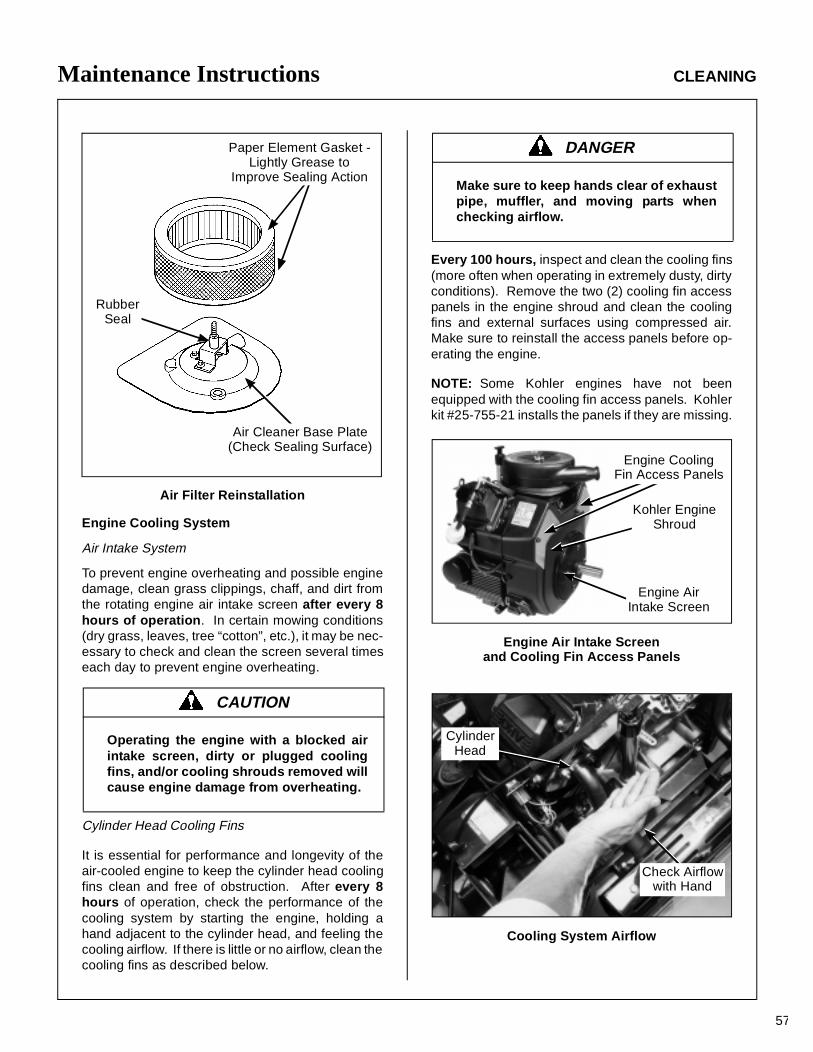
Maintenance Instructions CLEANING
57
Air Filter Reinstallation
Engine Cooling System
Air Intake System
To prevent engine overheating and possible enginedamage, clean grass clippings, chaff, and dirt fromthe rotating engine air intake screen after every 8hours of operation. In certain mowing conditions(dry grass, leaves, tree “cotton”, etc.), it may be nec-essary to check and clean the screen several timeseach day to prevent engine overheating.
Cylinder Head Cooling Fins
It is essential for performance and longevity of theair-cooled engine to keep the cylinder head coolingfins clean and free of obstruction. After every 8hours of operation, check the performance of thecooling system by starting the engine, holding ahand adjacent to the cylinder head, and feeling thecooling airflow. If there is little or no airflow, clean thecooling fins as described below.
Every 100 hours, inspect and clean the cooling fins(more often when operating in extremely dusty, dirtyconditions). Remove the two (2) cooling fin accesspanels in the engine shroud and clean the coolingfins and external surfaces using compressed air.Make sure to reinstall the access panels before op-erating the engine.
NOTE: Some Kohler engines have not beenequipped with the cooling fin access panels. Kohlerkit #25-755-21 installs the panels if they are missing.
Engine Air Intake Screenand Cooling Fin Access Panels
Cooling System Airflow
CAUTION
Operating the engine with a blocked airintake screen, dirty or plugged coolingfins, and/or cooling shrouds removed willcause engine damage from overheating.
Paper Element Gasket -Lightly Grease to
Improve Sealing Action
Air Cleaner Base Plate(Check Sealing Surface)
RubberSeal
DANGER
Make sure to keep hands clear of exhaustpipe, muffler, and moving parts whenchecking airflow.
Engine AirIntake Screen
Kohler EngineShroud
Engine CoolingFin Access Panels
CylinderHead
Check Airflowwith Hand
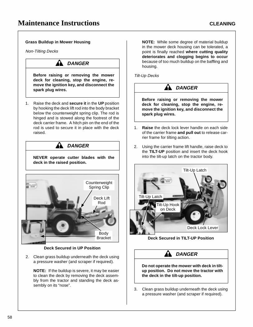
Maintenance Instructions CLEANING
58
Grass Buildup in Mower Housing
Non-Tilting Decks
1. Raise the deck and secure it in the UP positionby hooking the deck lift rod into the body bracketbelow the counterweight spring clip. The rod ishinged and is stowed along the footrest of thedeck carrier frame. A hitch pin on the end of therod is used to secure it in place with the deckraised.
Deck Secured in UP Position
-2. Clean grass buildup underneath the deck usinga pressure washer (and scraper if required).
NOTE: If the buildup is severe, it may be easierto clean the deck by removing the deck assem-bly from the tractor and standing the deck as-sembly on its “nose”.
NOTE: While some degree of material buildupin the mower deck housing can be tolerated, apoint is finally reached where cutting qualitydeteriorates and clogging begins to occurbecause of too much buildup on the baffling andhousing.
Tilt-Up Decks
1. Raise the deck lock lever handle on each sideof the carrier frame and pull out to release car-rier frame for tilting action.
2. Using the carrier frame lift handle, raise deck tothe TILT-UP position and insert the deck hookinto the tilt-up latch on the tractor body.
Deck Secured in TILT-UP Position
3. Clean grass buildup underneath the deck usinga pressure washer (and scraper if required).
DANGER
Before raising or removing the mowerdeck for cleaning, stop the engine, re-move the ignition key, and disconnect thespark plug wires.
DANGER
NEVER operate cutter blades with thedeck in the raised position.
CounterweightSpring Clip
Deck LiftRod
BodyBracket
DANGER
Before raising or removing the mowerdeck for cleaning, stop the engine, re-move the ignition key, and disconnect thespark plug wires.
DANGER
Do not operate the mower with deck in tilt-up position. Do not move the tractor withthe deck in the tilt-up position.
Tilt-Up Latch
Deck Lock Lever
Tilt-Up Latch
Tilt-Up Hookon Deck
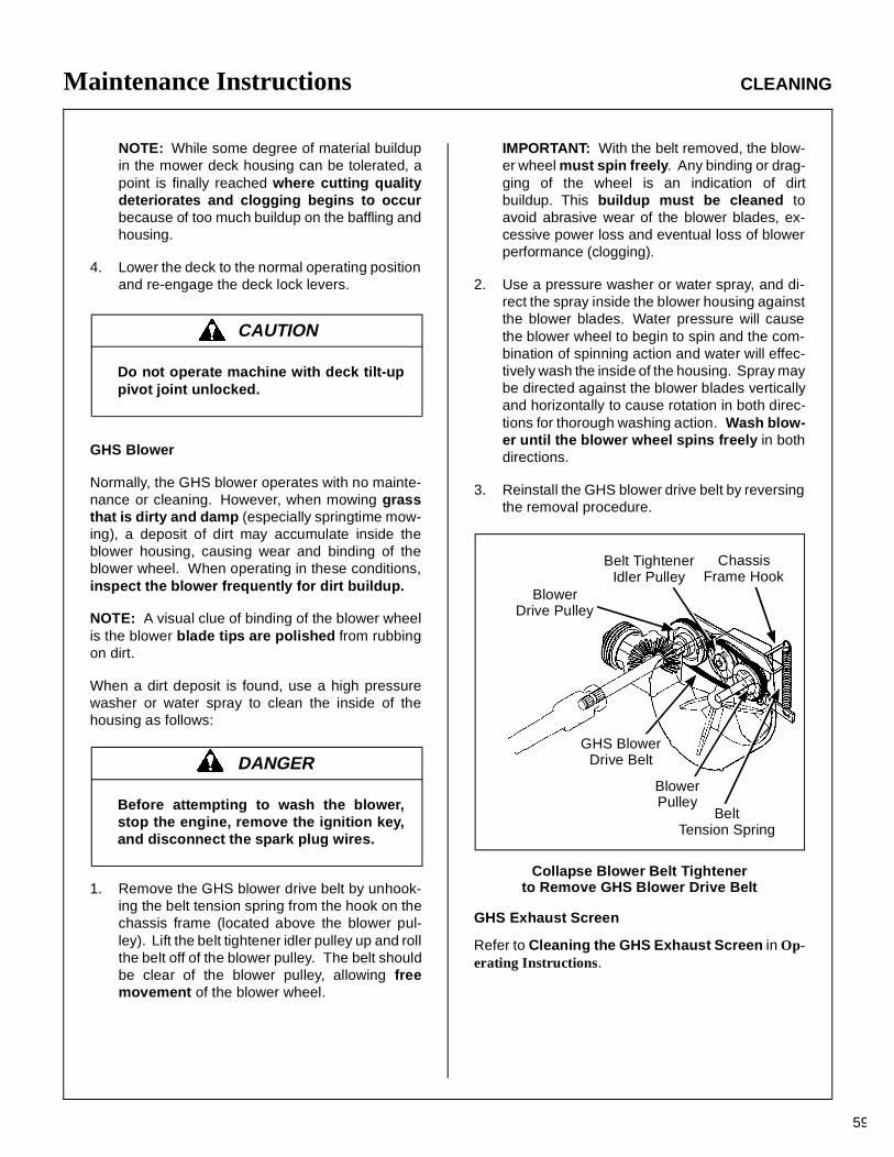
Maintenance Instructions CLEANING
59
NOTE: While some degree of material buildupin the mower deck housing can be tolerated, apoint is finally reached where cutting qualitydeteriorates and clogging begins to occurbecause of too much buildup on the baffling andhousing.
4. Lower the deck to the normal operating positionand re-engage the deck lock levers.
GHS Blower
Normally, the GHS blower operates with no mainte-nance or cleaning. However, when mowing grassthat is dirty and damp (especially springtime mow-ing), a deposit of dirt may accumulate inside theblower housing, causing wear and binding of theblower wheel. When operating in these conditions,inspect the blower frequently for dirt buildup.
NOTE: A visual clue of binding of the blower wheelis the blower blade tips are polished from rubbingon dirt.
When a dirt deposit is found, use a high pressurewasher or water spray to clean the inside of thehousing as follows:
1. Remove the GHS blower drive belt by unhook-ing the belt tension spring from the hook on thechassis frame (located above the blower pul-ley). Lift the belt tightener idler pulley up and rollthe belt off of the blower pulley. The belt shouldbe clear of the blower pulley, allowing freemovement of the blower wheel.
IMPORTANT: With the belt removed, the blow-er wheel must spin freely. Any binding or drag-ging of the wheel is an indication of dirtbuildup. This buildup must be cleaned toavoid abrasive wear of the blower blades, ex-cessive power loss and eventual loss of blowerperformance (clogging).
2. Use a pressure washer or water spray, and di-rect the spray inside the blower housing againstthe blower blades. Water pressure will causethe blower wheel to begin to spin and the com-bination of spinning action and water will effec-tively wash the inside of the housing. Spray maybe directed against the blower blades verticallyand horizontally to cause rotation in both direc-tions for thorough washing action. Wash blow-er until the blower wheel spins freely in bothdirections.
3. Reinstall the GHS blower drive belt by reversingthe removal procedure.
Collapse Blower Belt Tightenerto Remove GHS Blower Drive Belt
GHS Exhaust Screen
Refer to Cleaning the GHS Exhaust Screen in Op-erating Instructions.
CAUTION
Do not operate machine with deck tilt-uppivot joint unlocked.
DANGER
Before attempting to wash the blower,stop the engine, remove the ignition key,and disconnect the spark plug wires.
BeltTension Spring
ChassisFrame Hook
Belt TightenerIdler Pulley
GHS BlowerDrive Belt
BlowerPulley
BlowerDrive Pulley
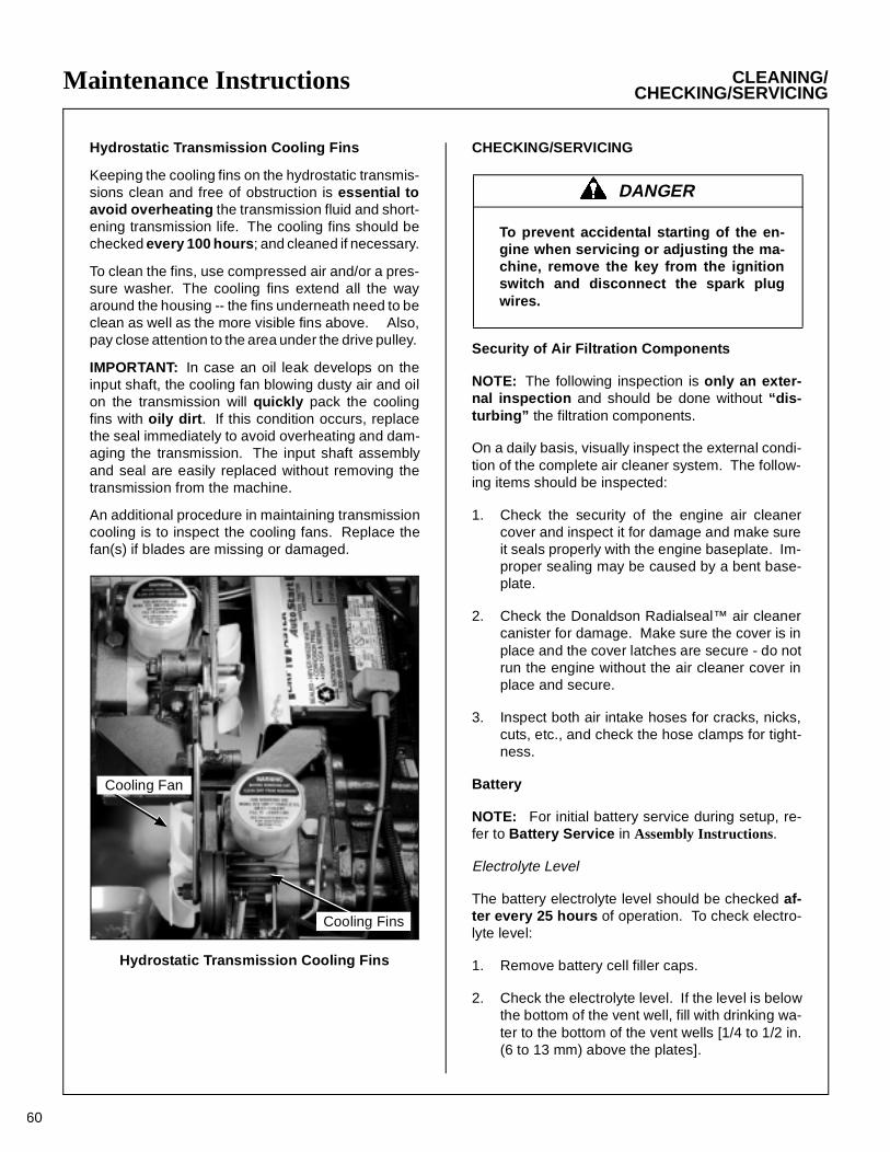
60
Maintenance Instructions CLEANING/CHECKING/SERVICING
Hydrostatic Transmission Cooling Fins
Keeping the cooling fins on the hydrostatic transmis-sions clean and free of obstruction is essential toavoid overheating the transmission fluid and short-ening transmission life. The cooling fins should bechecked every 100 hours; and cleaned if necessary.
To clean the fins, use compressed air and/or a pres-sure washer. The cooling fins extend all the wayaround the housing -- the fins underneath need to beclean as well as the more visible fins above. Also,pay close attention to the area under the drive pulley.
IMPORTANT: In case an oil leak develops on theinput shaft, the cooling fan blowing dusty air and oilon the transmission will quickly pack the coolingfins with oily dirt. If this condition occurs, replacethe seal immediately to avoid overheating and dam-aging the transmission. The input shaft assemblyand seal are easily replaced without removing thetransmission from the machine.
An additional procedure in maintaining transmissioncooling is to inspect the cooling fans. Replace thefan(s) if blades are missing or damaged.
Hydrostatic Transmission Cooling Fins
CHECKING/SERVICING
Security of Air Filtration Components
NOTE: The following inspection is only an exter-nal inspection and should be done without “dis-turbing” the filtration components.
On a daily basis, visually inspect the external condi-tion of the complete air cleaner system. The follow-ing items should be inspected:
1. Check the security of the engine air cleanercover and inspect it for damage and make sureit seals properly with the engine baseplate. Im-proper sealing may be caused by a bent base-plate.
2. Check the Donaldson Radialseal™ air cleanercanister for damage. Make sure the cover is inplace and the cover latches are secure - do notrun the engine without the air cleaner cover inplace and secure.
3. Inspect both air intake hoses for cracks, nicks,cuts, etc., and check the hose clamps for tight-ness.
Battery
NOTE: For initial battery service during setup, re-fer to Battery Service in Assembly Instructions.
Electrolyte Level
The battery electrolyte level should be checked af-ter every 25 hours of operation. To check electro-lyte level:
1. Remove battery cell filler caps.
2. Check the electrolyte level. If the level is belowthe bottom of the vent well, fill with drinking wa-ter to the bottom of the vent wells [1/4 to 1/2 in.(6 to 13 mm) above the plates].
Cooling Fins
Cooling Fan
DANGER
To prevent accidental starting of the en-gine when servicing or adjusting the ma-chine, remove the key from the ignitionswitch and disconnect the spark plugwires.
61
Maintenance Instructions CHECKING/SERVICING
3. Replace filler caps.
IMPORTANT: DO NOT overfill the battery. Electro-lyte will overflow through the vented caps onto partsof the machine and WILL result in severe corrosion.
Cleaning the Terminals
If battery terminals are corroded, remove batteryfrom the mower. Using a wire brush, remove corro-sion with a solution of one part baking soda andfour parts water. Rinse with clean water. Coat theterminals with petroleum jelly or terminal protectorspray to retard further corrosion.
Charging the Battery
Check the battery charge by measuring the specificgravity of electrolyte; if specific gravity is less than1.225, the battery will need to be charged as follows:
1. Charge the battery at 15 amps for 10 minutes.DO NOT exceed 20 amps maximum recom-mended charging rate. Charge until specificgravity is at least 1.250. Total charging timeshould not exceed one (1) hour.
2. After charging the battery, use drinking water toadjust the electrolyte level to the bottom of thevent wells [1/4 to 1/2 in. (6 to 13 mm) above theplates].
Tire Pressure
Inflate tires to pressures shown below:
Deck Caster Wheel = 20 PSI (137 kPa)Drive = 15 PSI (103 kPa)Rear = 20 PSI (137 kPa)
Sharpen Mower Blades
Check mower blade(s) for straightness, sharp-ness, condition of the cutting edge, and balanceevery 10 hours of operation (or more often whenmowing abrasive type grass or operating on sandysoils). Replace blades if worn, bent, cracked, orotherwise damaged (refer to REPLACING/RE-PAIRING the Mower Blades in this section). Use thefollowing procedure to check and sharpen blades:
NOTE: Keep blades sharp - cutting with dullblades not only yields a poor mowing job but slowsthe cutting speed of the mower and causes extrawear on the engine and blade drive by pulling hard.
1. Stop the engine, remove ignition key, and dis-connect the spark plug wires before raising themower deck to service blades.
2. Raise the deck and secure it in either the UP po-sition using the deck lift rod (non-tilt deck) or inthe TILT-UP position. Refer to CLEANING theGrass Buildup in Mower Housing in this sec-tion for deck raising instructions.
3. Check the blades for straightness by markingthe blade tip position inside the deck housing,and then rotating the opposite end of the bladeto the same position and comparing. If the dif-ference in blade tip track is more than 1/8 in.(3 mm), the blade is bent and should be re-placed.
DANGER
BATTERIES PRODUCE EXPLOSIVE GASES
• Charge the battery in a well-ventilatedarea, so that gases produced while charg-ing can dissipate.
• Keep sparks, flames, and smoking ma-terials away from the battery at all times.
• Make sure the battery cap vents are open(check manifold vent on each cap).
• Make sure the battery charger is un-plugged before connecting or discon-necting cables to the battery.
DANGER
NEVER operate cutter blades with thedeck in the raised position.
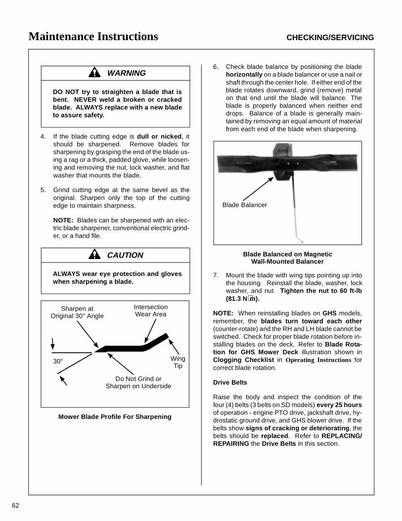
Maintenance Instructions CHECKING/SERVICING
62
4. If the blade cutting edge is dull or nicked, itshould be sharpened. Remove blades forsharpening by grasping the end of the blade us-ing a rag or a thick, padded glove, while loosen-ing and removing the nut, lock washer, and flatwasher that mounts the blade.
5. Grind cutting edge at the same bevel as theoriginal. Sharpen only the top of the cuttingedge to maintain sharpness.
NOTE: Blades can be sharpened with an elec-tric blade sharpener, conventional electric grind-er, or a hand file.
Mower Blade Profile For Sharpening
6. Check blade balance by positioning the bladehorizontally on a blade balancer or use a nail orshaft through the center hole. If either end of theblade rotates downward, grind (remove) metalon that end until the blade will balance. Theblade is properly balanced when neither enddrops. Balance of a blade is generally main-tained by removing an equal amount of materialfrom each end of the blade when sharpening.
Blade Balanced on MagneticWall-Mounted Balancer
7. Mount the blade with wing tips pointing up intothe housing. Reinstall the blade, washer, lockwasher, and nut. Tighten the nut to 60 ft-lb(81.3 N⋅m).
NOTE: When reinstalling blades on GHS models,remember, the blades turn toward each other(counter-rotate) and the RH and LH blade cannot beswitched. Check for proper blade rotation before in-stalling blades on the deck. Refer to Blade Rota-tion for GHS Mower Deck illustration shown inClogging Checklist in Operating Instructions forcorrect blade rotation.
Drive Belts
Raise the body and inspect the condition of thefour (4) belts (3 belts on SD models) every 25 hoursof operation - engine PTO drive, jackshaft drive, hy-drostatic ground drive, and GHS blower drive. If thebelts show signs of cracking or deteriorating, thebelts should be replaced. Refer to REPLACING/REPAIRING the Drive Belts in this section.
WARNING
DO NOT try to straighten a blade that isbent. NEVER weld a broken or crackedblade. ALWAYS replace with a new bladeto assure safety.
CAUTION
ALWAYS wear eye protection and gloveswhen sharpening a blade.
30°
Do Not Grind orSharpen on Underside
Sharpen atOriginal 30° Angle
IntersectionWear Area
WingTip
Blade Balancer
63
Maintenance Instructions CHECKING/SERVICING/REPLACING/REPAIRING
Mower Deck Gearbox Oil Seals
The mower deck gearbox seals should be inspectedevery 25 hours for evidence of oil leaking; particu-larly the lower oil seal on the blade drive gear-box. This seal is protected by the trash guard on theblade hub and seal protector plate on the housing,but is still vulnerable to seal damage due to operat-ing in an adverse environment. The mower blademust be removed for inspection of the seal, so it isrecommended to inspect the gearbox seals whenblades are removed for sharpening. If an oil leakis noted, the seal should be replaced and the gear-box assembly relubricated. Refer to Mower DeckGearbox Lubrication in this section.
Spark Plugs
Every 200 hours of operation, remove the sparkplugs, inspect, clean, and reset the gap (or replacewith new plugs). Before removing the spark plugs,clean the area around the base of the plugs to keepdirt and debris out of the engine. Clean spark plugswith a wire brush. DO NOT use an abrasive grit typecleaner. If the electrodes are burned short or pitted,replace plugs with Champion type RC12YC (orequivalent). Check spark plug gap with a wire-typefeeler gauge and set the gap at 0.030 in. (.76 mm).Reinstall and tighten to between 18 and 22 ft-lb(24.4 to 29.8 N⋅m).
Fuel Lines and Clamps
Every year, inspect the fuel supply line from the tankto engine for deterioration or damage. Also, inspectthe fuel line clamps for tightness. Good preventivemaintenance calls for complete replace-ment of fuellines and clamps every two (2) years.
Engine Starter
Yearly or every 500 hours disassemble and cleanthe solenoid shift starter. Refer to the Kohler ServiceManual for this procedure or contact an authorizedKohler engine dealer to perform this service.
Blade Brake Action
Check the function of the cutter blade brake (andblower brake on GHS models) by engaging the bladeclutch (PTO), operating the engine at full throttle, thendisengaging the clutch and measuring how quicklythe blades stop. Watch the rotation of the blade driveshaft and blower pulley as a visual indication thatmovement has stopped. If the brake is workingproperly, all rotation will stop five (5) seconds af-ter disengagement of the clutch. If the brake sys-tem malfunctions - blades do not stop in five (5)seconds - adjust or repair the brake before operatingthe mower. Refer to ADJUSTMENTS of BladeClutch (PTO) in this section.
REPLACING/REPAIRING
IMPORTANT: ALWAYS use genuine factory re-placement parts. Substitute parts CAN result inproduct malfunction and possible injury to the oper-ator and/or others.
Drive Belts
There are four (4) individual belts on GHS modelsor three (3) belts on SD models:
• Jackshaft Drive Belt
• Engine PTO Drive Belt (3 Groove Power Band)
• GHS Blower Drive Belt (GHS Model Only)
• Hydrostatic Ground Drive Belt
The belts may be removed and replaced using theprocedures described on the following pages.
WARNING
It is important to check and maintain bladebrake action for safe operation of the ma-chine.
DANGER
To prevent accidental starting of the en-gine when replacing parts or repairing themachine, remove the key from the ignitionswitch and disconnect the spark plugwires.
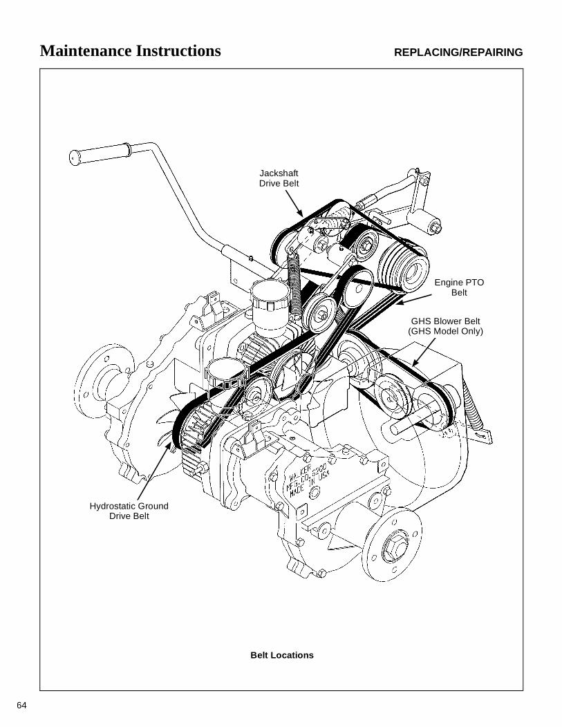
Maintenance Instructions REPLACING/REPAIRING
64
JackshaftDrive Belt
Engine PTOBelt
GHS Blower Belt(GHS Model Only)
Hydrostatic GroundDrive Belt
Belt Locations
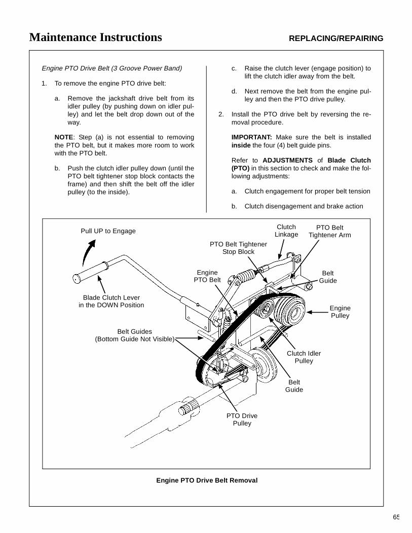
Maintenance Instructions REPLACING/REPAIRING
65
Engine PTO Drive Belt (3 Groove Power Band)
1. To remove the engine PTO drive belt:
a. Remove the jackshaft drive belt from itsidler pulley (by pushing down on idler pul-ley) and let the belt drop down out of theway.
NOTE: Step (a) is not essential to removingthe PTO belt, but it makes more room to workwith the PTO belt.
b. Push the clutch idler pulley down (until thePTO belt tightener stop block contacts theframe) and then shift the belt off the idlerpulley (to the inside).
c. Raise the clutch lever (engage position) tolift the clutch idler away from the belt.
d. Next remove the belt from the engine pul-ley and then the PTO drive pulley.
2. Install the PTO drive belt by reversing the re-moval procedure.
IMPORTANT: Make sure the belt is installedinside the four (4) belt guide pins.
Refer to ADJUSTMENTS of Blade Clutch(PTO) in this section to check and make the fol-lowing adjustments:
a. Clutch engagement for proper belt tension
b. Clutch disengagement and brake action
Engine PTO Drive Belt Removal
Pull UP to Engage
EnginePTO Belt
ClutchLinkage
PTO BeltTightener Arm
EnginePulley
Clutch IdlerPulley
BeltGuide
Belt Guides(Bottom Guide Not Visible)
Blade Clutch Leverin the DOWN Position
PTO DrivePulley
BeltGuide
PTO Belt TightenerStop Block
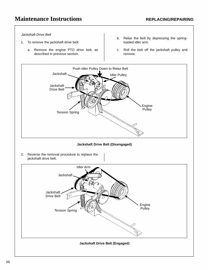
Maintenance Instructions REPLACING/REPAIRING
66
Jackshaft Drive Belt
1. To remove the jackshaft drive belt:
a. Remove the engine PTO drive belt, asdescribed in previous section.
Jackshaft Drive Belt (Engaged)
Jackshaft Drive Belt (Disengaged)
Push Idler Pulley Down to Relax Belt
Idler Pulley
EnginePulley
Tension Spring
Jackshaft
JackshaftDrive Belt
b. Relax the belt by depressing the spring-loaded idler arm.
c. Roll the belt off the jackshaft pulley andremove.
2. Reverse the removal procedure to replace thejackshaft drive belt.
Idler Arm
Jackshaft
JackshaftDrive Belt
Tension Spring
EnginePulley
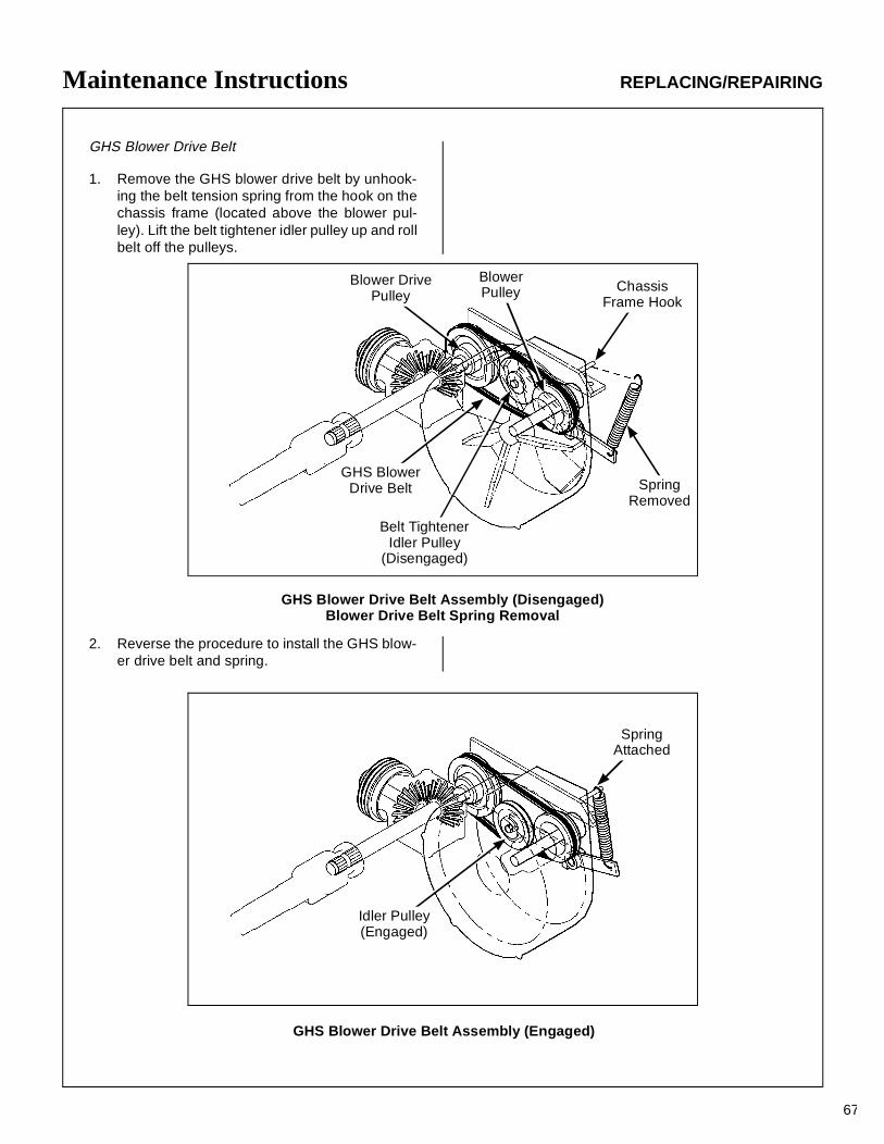
Maintenance Instructions REPLACING/REPAIRING
67
GHS Blower Drive Belt
1. Remove the GHS blower drive belt by unhook-ing the belt tension spring from the hook on thechassis frame (located above the blower pul-ley). Lift the belt tightener idler pulley up and rollbelt off the pulleys.
ChassisFrame Hook
BlowerPulley
Belt TightenerIdler Pulley
(Disengaged)
Blower DrivePulley
SpringRemoved
GHS BlowerDrive Belt
SpringAttached
Idler Pulley(Engaged)
GHS Blower Drive Belt Assembly (Disengaged)Blower Drive Belt Spring Removal
2. Reverse the procedure to install the GHS blow-er drive belt and spring.
GHS Blower Drive Belt Assembly (Engaged)
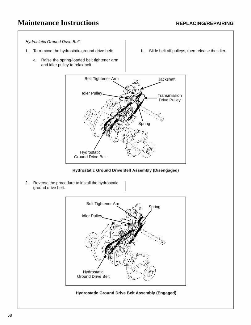
Maintenance Instructions REPLACING/REPAIRING
68
Hydrostatic Ground Drive Belt
1. To remove the hydrostatic ground drive belt:
a. Raise the spring-loaded belt tightener armand idler pulley to relax belt.
b. Slide belt off pulleys, then release the idler.
HydrostaticGround Drive Belt
Idler Pulley
Belt Tightener Arm Jackshaft
TransmissionDrive Pulley
Spring
Hydrostatic Ground Drive Belt Assembly (Disengaged)
2. Reverse the procedure to install the hydrostaticground drive belt.
Belt Tightener Arm
Idler Pulley
HydrostaticGround Drive Belt
Spring
Hydrostatic Ground Drive Belt Assembly (Engaged)
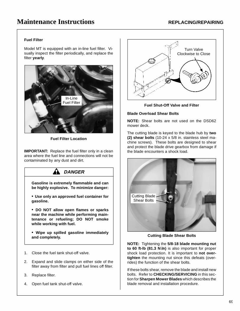
Maintenance Instructions REPLACING/REPAIRING
69
Fuel Filter
Model MT is equipped with an in-line fuel filter. Vi-sually inspect the filter periodically, and replace thefilter yearly.
Fuel Filter Location
IMPORTANT: Replace the fuel filter only in a cleanarea where the fuel line and connections will not becontaminated by any dust and dirt.
1. Close the fuel tank shut-off valve.
2. Expand and slide clamps on either side of thefilter away from filter and pull fuel lines off filter.
3. Replace filter.
4. Open fuel tank shut-off valve.
Fuel Shut-Off Valve and Filter
Blade Overload Shear Bolts
NOTE: Shear bolts are not used on the DSD62mower deck.
The cutting blade is keyed to the blade hub by two(2) shear bolts (10-24 x 5/8 in. stainless steel ma-chine screws). These bolts are designed to shearand protect the blade drive gearbox from damage ifthe blade encounters a shock load.
Cutting Blade Shear Bolts
NOTE: Tightening the 5/8-18 blade mounting nutto 60 ft-lb (81.3 N⋅m) is also important for propershock load protection. It is important to not over-tighten the mounting nut since this defeats (over-rides) the function of the shear bolts.
If these bolts shear, remove the blade and install newbolts. Refer to CHECKING/SERVICING in this sec-tion for Sharpen Mower Blades which describes theblade removal and installation procedure.
DANGER
Gasoline is extremely flammable and canbe highly explosive. To minimize danger:
• Use only an approved fuel container forgasoline.
• DO NOT allow open flames or sparksnear the machine while performing main-tenance or refueling; DO NOT smokewhile working with fuel.
• Wipe up spilled gasoline immediatelyand completely.
In-LineFuel Filter
Turn Valve Clockwise to Close
Cutting BladeShear Bolts
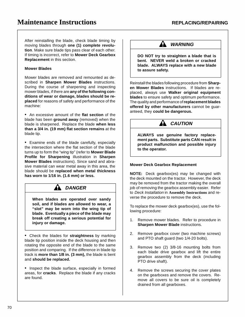
Maintenance Instructions REPLACING/REPAIRING
70
After reinstalling the blade, check blade timing bymoving blades through one (1) complete revolu-tion. Make sure blade tips pass clear of each other.If timing is incorrect, refer to Mower Deck GearboxReplacement in this section.
Mower Blades
Mower blades are removed and remounted as de-scribed in Sharpen Mower Blades instructions.During the course of sharpening and inspectingmower blades, if there are any of the following con-ditions of wear or damage, blades should be re-placed for reasons of safety and performance of themachine:
• An excessive amount of the flat section of theblade has been ground away (removed) when theblade is sharpened. Replace the blade when lessthan a 3/4 in. (19 mm) flat section remains at theblade tip.
• Examine ends of the blade carefully, especiallythe intersection where the flat section of the bladeturns up to form the “wing tip” (refer to Mower BladeProfile for Sharpening illustration in SharpenMower Blades instructions). Since sand and abra-sive material can wear metal away in this area, theblade should be replaced when metal thicknesshas worn to 1/16 in. (1.6 mm) or less.
• Check the blades for straightness by markingblade tip position inside the deck housing and thenrotating the opposite end of the blade to the sameposition and comparing. If the difference in blade tiptrack is more than 1/8 in. (3 mm), the blade is bentand should be replaced.
• Inspect the blade surface, especially in formedareas, for cracks. Replace the blade if any cracksare found.
Reinstall the blades following procedure from Sharp-en Mower Blades instructions. If blades are re-placed, always use Walker original equipmentblades to ensure safety and optimum performance.The quality and performance of replacement bladesoffered by other manufacturers cannot be guar-anteed, they could be dangerous.
Mower Deck Gearbox Replacement
NOTE: Deck gearbox(es) may be changed withthe deck mounted on the tractor. However, the deckmay be removed from the tractor making the overalljob of removing the gearbox assembly easier. Referto Deck Installation in Assembly Instructions and re-verse the procedure to remove the deck.
To replace the mower deck gearbox(es), use the fol-lowing procedure:
1. Remove mower blades. Refer to procedure inSharpen Mower Blade instructions.
2. Remove gearbox cover (two machine screws)and PTO shaft guard (two 1/4-20 bolts).
3. Remove two (2) 3/8-16 mounting bolts fromeach blade drive gearbox and lift the entiregearbox assembly from the deck (includingPTO drive shaft).
4. Remove the screws securing the cover plateson the gearboxes and remove the covers. Re-move all covers to be sure oil is completelydrained from all gearboxes.
DANGER
When blades are operated over sandysoil, and if blades are allowed to wear, a“slot” may be worn into the wing tip ofblade. Eventually a piece of the blade maybreak off creating a serious potential forinjury or damage.
WARNING
DO NOT try to straighten a blade that isbent. NEVER weld a broken or crackedblade. ALWAYS replace with a new bladeto assure safety.
CAUTION
ALWAYS use genuine factory replace-ment parts. Substitute parts CAN result inproduct malfunction and possible injuryto the operator.
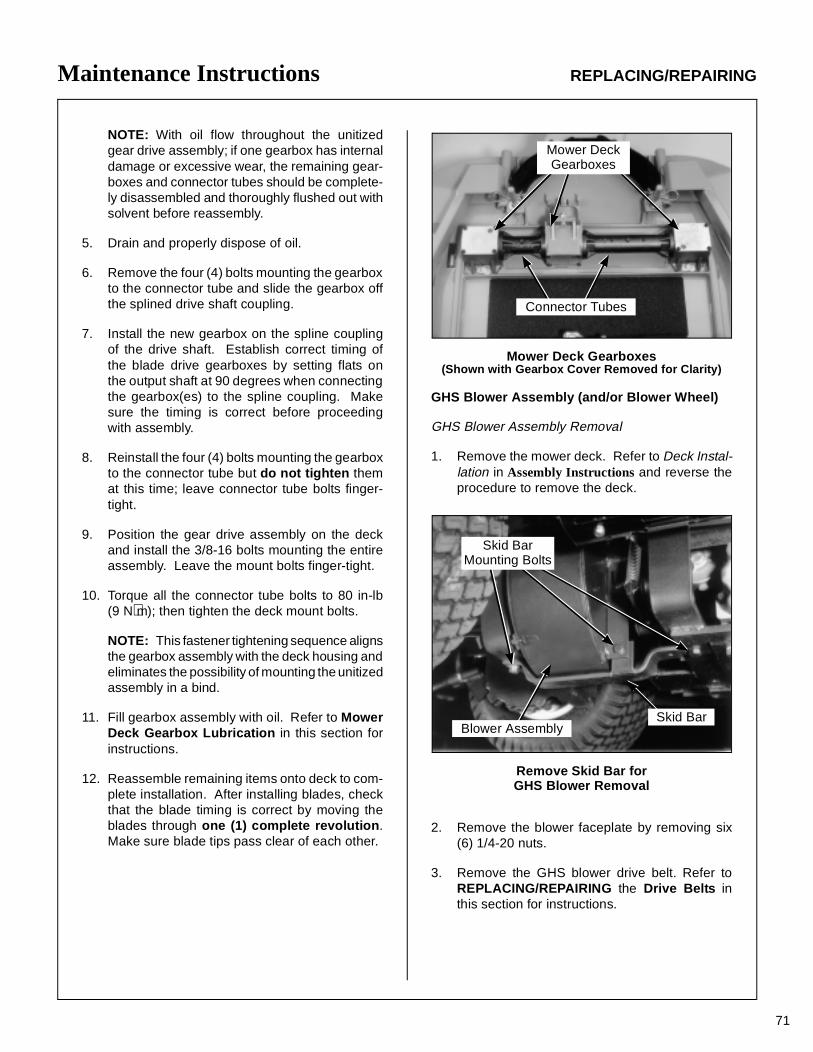
Maintenance Instructions REPLACING/REPAIRING
71
NOTE: With oil flow throughout the unitizedgear drive assembly; if one gearbox has internaldamage or excessive wear, the remaining gear-boxes and connector tubes should be complete-ly disassembled and thoroughly flushed out withsolvent before reassembly.
5. Drain and properly dispose of oil.
6. Remove the four (4) bolts mounting the gearboxto the connector tube and slide the gearbox offthe splined drive shaft coupling.
7. Install the new gearbox on the spline couplingof the drive shaft. Establish correct timing ofthe blade drive gearboxes by setting flats onthe output shaft at 90 degrees when connectingthe gearbox(es) to the spline coupling. Makesure the timing is correct before proceedingwith assembly.
8. Reinstall the four (4) bolts mounting the gearboxto the connector tube but do not tighten themat this time; leave connector tube bolts finger-tight.
9. Position the gear drive assembly on the deckand install the 3/8-16 bolts mounting the entireassembly. Leave the mount bolts finger-tight.
10. Torque all the connector tube bolts to 80 in-lb(9 N⋅m); then tighten the deck mount bolts.
NOTE: This fastener tightening sequence alignsthe gearbox assembly with the deck housing andeliminates the possibility of mounting the unitizedassembly in a bind.
11. Fill gearbox assembly with oil. Refer to MowerDeck Gearbox Lubrication in this section forinstructions.
12. Reassemble remaining items onto deck to com-plete installation. After installing blades, checkthat the blade timing is correct by moving theblades through one (1) complete revolution.Make sure blade tips pass clear of each other.
Mower Deck Gearboxes(Shown with Gearbox Cover Removed for Clarity)
GHS Blower Assembly (and/or Blower Wheel)
GHS Blower Assembly Removal
1. Remove the mower deck. Refer to Deck Instal-lation in Assembly Instructions and reverse theprocedure to remove the deck.
Remove Skid Bar forGHS Blower Removal
2. Remove the blower faceplate by removing six(6) 1/4-20 nuts.
3. Remove the GHS blower drive belt. Refer toREPLACING/REPAIRING the Drive Belts inthis section for instructions.
Mower DeckGearboxes
Connector Tubes
Skid BarMounting Bolts
Blower AssemblySkid Bar
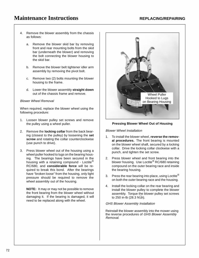
Maintenance Instructions REPLACING/REPAIRING
72
4. Remove the blower assembly from the chassisas follows:
a. Remove the blower skid bar by removingfront and rear mounting bolts from the skidbar (underneath the blower) and removingthe bolt connecting the blower housing tothe skid bar.
b. Remove the blower belt tightener idler armassembly by removing the pivot bolt.
c. Remove two (2) bolts mounting the blowerhousing to the frame.
d. Lower the blower assembly straight downout of the chassis frame and remove.
Blower Wheel Removal
When required, replace the blower wheel using thefollowing procedure:
1. Loosen blower pulley set screws and removethe pulley using a wheel puller.
2. Remove the locking collar from the back bear-ing (closest to the pulley) by loosening the setscrew and rotating the collar counterclockwise(use punch to drive).
3. Press blower wheel out of the housing using awheel puller hooked to lugs on the bearing hous-ing. The bearings have been secured in thehousing with a retaining compound - Loctite®
RC/680, and considerable force will be re-quired to break this bond. After the bearingshave “broken loose” from the housing, only lightpressure should be required to remove thewheel assembly out of the housing.
NOTE: It may or may not be possible to removethe front bearing from the blower wheel withoutdamaging it. If the bearing is damaged, it willneed to be replaced along with the wheel.
Pressing Blower Wheel Out of Housing
Blower Wheel Installation
1. To install the blower wheel, reverse the remov-al procedures. The front bearing is mountedon the blower wheel shaft, secured by a lockingcollar. Drive the locking collar clockwise with apunch, and tighten the set screw.
2. Press blower wheel and front bearing into theblower housing. Use Loctite® RC/680 retainingcompound on the outer bearing race and insidethe bearing housing.
3. Press the rear bearing into place, using Loctite®
on both the outer bearing race and the housing.
4. Install the locking collar on the rear bearing andinstall the blower pulley to complete the blowerassembly. Torque the blower pulley set screwsto 250 in-lb (28.3 N⋅m).
GHS Blower Assembly Installation
Reinstall the blower assembly into the mower using the reverse procedures of GHS Blower Assembly Removal.
Wheel PullerHooked to Lugs
on Bearing Housing
73
Maintenance Instructions ADJUSTMENTS
ADJUSTMENTS
Safety Switches
There are three (3) safety interlock switches on thetractor. Use the panel nuts on the switch body to po-sition the switch for proper activation of the switch.The adjustment procedure for each switch is:
Seat Switch
Adjust switch position in body panel to achieve a1/32 to 1/16 in. (.79 mm to 1.59 mm) air gap betweenthe switch plunger and seat frame with no weight onthe seat. Test for proper operation.
FSC Neutral-Park Switch
1. Place the FSC in NEUTRAL-PARK position.
2. Adjust switch to the point where the starter en-gages when the ignition switch is turned to thestart position.
3. Adjust switch position forward an additional 1/2to 1 turn of the panel nuts.
NOTE: If the switch cannot be adjusted forwardenough to achieve proper function, it may benecessary to bend the switch mounting bracketslightly.
PTO Switch
With the PTO engaged, adjust switch to achieve a1/64 to 1/32 in. (.40 mm to .79 mm) gap (plunger ex-tension) between the switch body and the actuatorplate.
Tail Wheel Bearing Preload
Preload the tail wheel bearings by tightening the ax-le nut until the wheel begins to tighten as it turns (notspin freely), then loosen the nut 1/2 to 1 turn. Thewheel should spin freely without excessive end play.Lock the axle nut with the set screw in the nut.
DANGER
If the engine must be running to performa maintenance adjustment, keep hands,feet, and clothing from moving parts. DONOT wear jewelry or loose clothing.
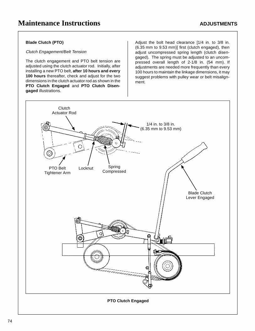
Maintenance Instructions ADJUSTMENTS
74
Blade Clutch (PTO)
Clutch Engagement/Belt Tension
The clutch engagement and PTO belt tension areadjusted using the clutch actuator rod. Initially, afterinstalling a new PTO belt, after 10 hours and every100 hours thereafter, check and adjust for the twodimensions in the clutch actuator rod as shown in thePTO Clutch Engaged and PTO Clutch Disen-gaged illustrations.
Adjust the bolt head clearance [1/4 in. to 3/8 in.(6.35 mm to 9.53 mm)] first (clutch engaged), thenadjust uncompressed spring length (clutch disen-gaged). The spring must be adjusted to an uncom-pressed overall length of 2-1/8 in. (54 mm). Ifadjustments are needed more frequently than every100 hours to maintain the linkage dimensions, it maysuggest problems with pulley wear or belt misalign-ment.
1/4 in. to 3/8 in.(6.35 mm to 9.53 mm)
ClutchActuator Rod
PTO BeltTightener Arm
Blade ClutchLever Engaged
SpringCompressed
Locknut
PTO Clutch Engaged
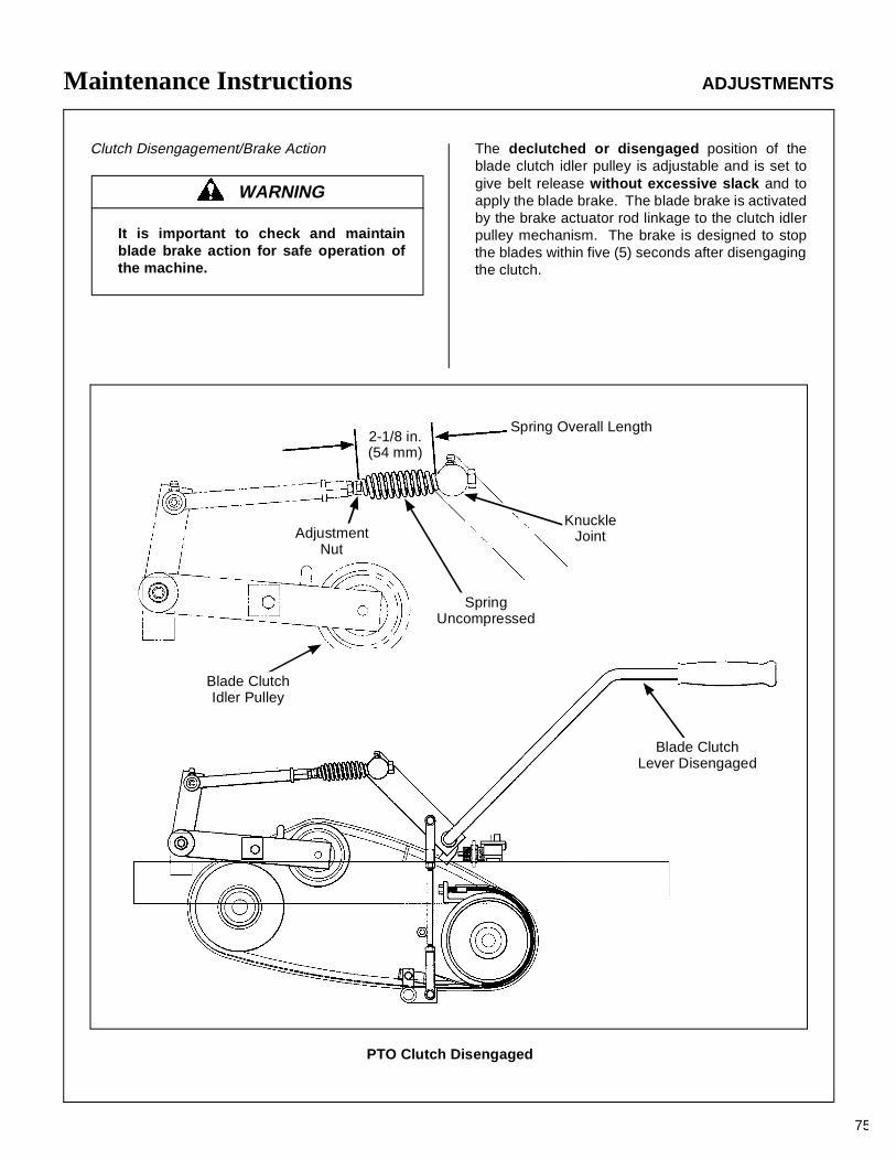
Maintenance Instructions ADJUSTMENTS
75
Clutch Disengagement/Brake Action The declutched or disengaged position of theblade clutch idler pulley is adjustable and is set togive belt release without excessive slack and toapply the blade brake. The blade brake is activatedby the brake actuator rod linkage to the clutch idlerpulley mechanism. The brake is designed to stopthe blades within five (5) seconds after disengagingthe clutch.
WARNING
It is important to check and maintainblade brake action for safe operation ofthe machine.
PTO Clutch Disengaged
Spring Overall Length2-1/8 in.(54 mm)
AdjustmentNut
SpringUncompressed
Blade ClutchIdler Pulley
Blade ClutchLever Disengaged
KnuckleJoint
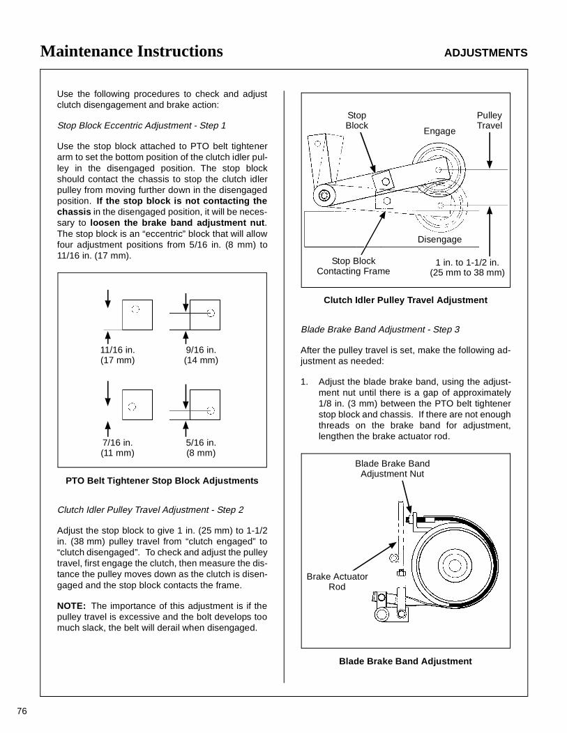
Maintenance Instructions ADJUSTMENTS
76
Use the following procedures to check and adjustclutch disengagement and brake action:
Stop Block Eccentric Adjustment - Step 1
Use the stop block attached to PTO belt tightenerarm to set the bottom position of the clutch idler pul-ley in the disengaged position. The stop blockshould contact the chassis to stop the clutch idlerpulley from moving further down in the disengagedposition. If the stop block is not contacting thechassis in the disengaged position, it will be neces-sary to loosen the brake band adjustment nut.The stop block is an “eccentric” block that will allowfour adjustment positions from 5/16 in. (8 mm) to11/16 in. (17 mm).
PTO Belt Tightener Stop Block Adjustments
Clutch Idler Pulley Travel Adjustment - Step 2
Adjust the stop block to give 1 in. (25 mm) to 1-1/2in. (38 mm) pulley travel from “clutch engaged” to“clutch disengaged”. To check and adjust the pulleytravel, first engage the clutch, then measure the dis-tance the pulley moves down as the clutch is disen-gaged and the stop block contacts the frame.
NOTE: The importance of this adjustment is if thepulley travel is excessive and the bolt develops toomuch slack, the belt will derail when disengaged.
Clutch Idler Pulley Travel Adjustment
Blade Brake Band Adjustment - Step 3
After the pulley travel is set, make the following ad-justment as needed:
1. Adjust the blade brake band, using the adjust-ment nut until there is a gap of approximately1/8 in. (3 mm) between the PTO belt tightenerstop block and chassis. If there are not enoughthreads on the brake band for adjustment,lengthen the brake actuator rod.
Blade Brake Band Adjustment
11/16 in.(17 mm)
9/16 in.(14 mm)
7/16 in.(11 mm)
5/16 in.(8 mm)
Engage
Disengage
PulleyTravel
1 in. to 1-1/2 in.(25 mm to 38 mm)
Stop BlockContacting Frame
StopBlock
Brake ActuatorRod
Blade Brake BandAdjustment Nut
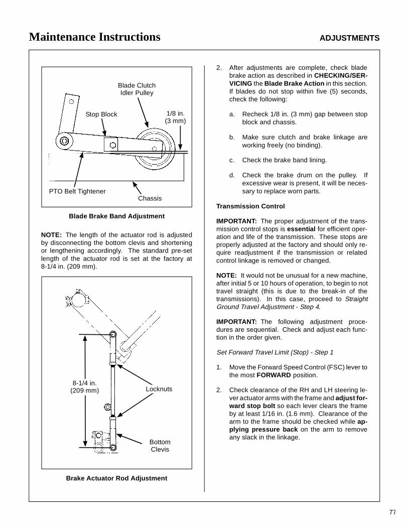
Maintenance Instructions ADJUSTMENTS
77
Blade Brake Band Adjustment
NOTE: The length of the actuator rod is adjustedby disconnecting the bottom clevis and shorteningor lengthening accordingly. The standard pre-setlength of the actuator rod is set at the factory at8-1/4 in. (209 mm).
Brake Actuator Rod Adjustment
2. After adjustments are complete, check bladebrake action as described in CHECKING/SER-VICING the Blade Brake Action in this section.If blades do not stop within five (5) seconds,check the following:
a. Recheck 1/8 in. (3 mm) gap between stopblock and chassis.
b. Make sure clutch and brake linkage areworking freely (no binding).
c. Check the brake band lining.
d. Check the brake drum on the pulley. Ifexcessive wear is present, it will be neces-sary to replace worn parts.
Transmission Control
IMPORTANT: The proper adjustment of the trans-mission control stops is essential for efficient oper-ation and life of the transmission. These stops areproperly adjusted at the factory and should only re-quire readjustment if the transmission or relatedcontrol linkage is removed or changed.
NOTE: It would not be unusual for a new machine,after initial 5 or 10 hours of operation, to begin to nottravel straight (this is due to the break-in of thetransmissions). In this case, proceed to StraightGround Travel Adjustment - Step 4.
IMPORTANT: The following adjustment proce-dures are sequential. Check and adjust each func-tion in the order given.
Set Forward Travel Limit (Stop) - Step 1
1. Move the Forward Speed Control (FSC) lever tothe most FORWARD position.
2. Check clearance of the RH and LH steering le-ver actuator arms with the frame and adjust for-ward stop bolt so each lever clears the frameby at least 1/16 in. (1.6 mm). Clearance of thearm to the frame should be checked while ap-plying pressure back on the arm to removeany slack in the linkage.
Blade ClutchIdler Pulley
1/8 in.(3 mm)
PTO Belt TightenerChassis
Stop Block
8-1/4 in.(209 mm)
BottomClevis
Locknuts
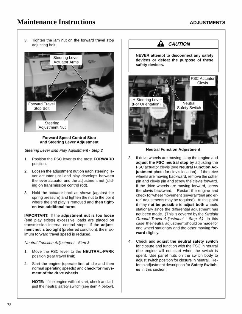
Maintenance Instructions ADJUSTMENTS
78
3. Tighten the jam nut on the forward travel stopadjusting bolt.
Forward Speed Control Stop and Steering Lever Adjustment
Steering Lever End Play Adjustment - Step 2
1. Position the FSC lever to the most FORWARDposition.
2. Loosen the adjustment nut on each steering le-ver actuator until end play develops betweenthe lever actuator and the adjustment nut (slid-ing on transmission control rod).
3. Hold the actuator back as shown (against thespring pressure) and tighten the nut to the pointwhere the end play is removed and then tight-en two additional turns.
IMPORTANT: If the adjustment nut is too loose(end play exists) excessive loads are placed ontransmission internal control stops. If the adjust-ment nut is too tight (preferred condition), the max-imum forward travel speed is reduced.
Neutral Function Adjustment - Step 3
1. Move the FSC lever to the NEUTRAL-PARKposition (rear travel limit).
2. Start the engine (operate first at idle and thennormal operating speeds) and check for move-ment of the drive wheels.
NOTE: If the engine will not start, check and ad-just the neutral safety switch (see item 4 below).
Neutral Function Adjustment
3. If drive wheels are moving, stop the engine andadjust the FSC neutral stop by adjusting theFSC actuator clevis (see Neutral Function Ad-justment photo for clevis location). If the drivewheels are moving backward, remove the cotterpin and clevis pin and screw the clevis forward.If the drive wheels are moving forward, screwthe clevis backward. Restart the engine andcheck for wheel movement (several “trial and er-ror” adjustments may be required). At this pointit may not be possible to adjust both wheelsstationary since the differential adjustment hasnot been made. (This is covered by the StraightGround Travel Adjustment - Step 4.) In thiscase, the neutral adjustment should be made forone wheel stationary and the other moving for-ward slightly.
4. Check and adjust the neutral safety switchfor closure and function with the FSC in neutral(the engine will not start when the switch isopen). Use panel nuts on the switch body toadjust switch position for closure in neutral. Re-fer to adjustment description for Safety Switch-es in this section.
Steering LeverActuator Arms
Forward TravelStop Bolt
SteeringAdjustment Nut
CAUTION
NEVER attempt to disconnect any safetydevices or defeat the purpose of thesesafety devices.
LH Steering Lever(For Orientation) Neutral
Safety Switch
FSC ActuatorClevis
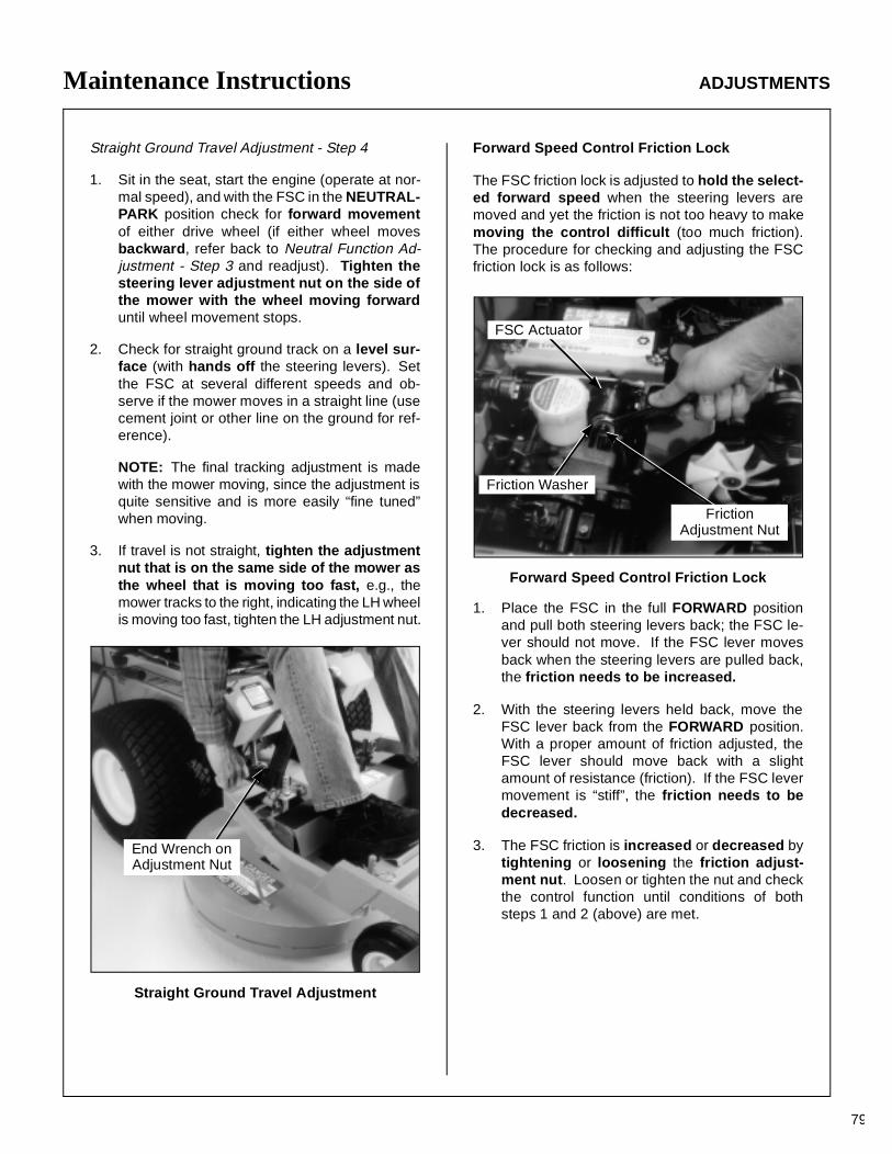
Maintenance Instructions ADJUSTMENTS
79
Straight Ground Travel Adjustment - Step 4
1. Sit in the seat, start the engine (operate at nor-mal speed), and with the FSC in the NEUTRAL-PARK position check for forward movementof either drive wheel (if either wheel movesbackward, refer back to Neutral Function Ad-justment - Step 3 and readjust). Tighten thesteering lever adjustment nut on the side ofthe mower with the wheel moving forwarduntil wheel movement stops.
2. Check for straight ground track on a level sur-face (with hands off the steering levers). Setthe FSC at several different speeds and ob-serve if the mower moves in a straight line (usecement joint or other line on the ground for ref-erence).
NOTE: The final tracking adjustment is madewith the mower moving, since the adjustment isquite sensitive and is more easily “fine tuned”when moving.
3. If travel is not straight, tighten the adjustmentnut that is on the same side of the mower asthe wheel that is moving too fast, e.g., themower tracks to the right, indicating the LH wheelis moving too fast, tighten the LH adjustment nut.
Straight Ground Travel Adjustment
Forward Speed Control Friction Lock
The FSC friction lock is adjusted to hold the select-ed forward speed when the steering levers aremoved and yet the friction is not too heavy to makemoving the control difficult (too much friction).The procedure for checking and adjusting the FSCfriction lock is as follows:
Forward Speed Control Friction Lock
1. Place the FSC in the full FORWARD positionand pull both steering levers back; the FSC le-ver should not move. If the FSC lever movesback when the steering levers are pulled back,the friction needs to be increased.
2. With the steering levers held back, move theFSC lever back from the FORWARD position.With a proper amount of friction adjusted, theFSC lever should move back with a slightamount of resistance (friction). If the FSC levermovement is “stiff”, the friction needs to bedecreased.
3. The FSC friction is increased or decreased bytightening or loosening the friction adjust-ment nut. Loosen or tighten the nut and checkthe control function until conditions of bothsteps 1 and 2 (above) are met.
End Wrench onAdjustment Nut
FSC Actuator
Friction Washer
FrictionAdjustment Nut
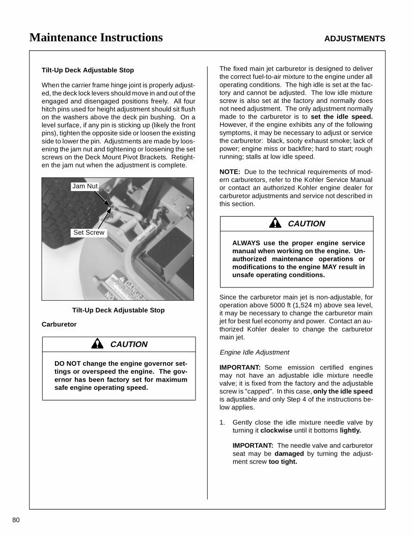
Maintenance Instructions ADJUSTMENTS
80
Tilt-Up Deck Adjustable Stop
When the carrier frame hinge joint is properly adjust-ed, the deck lock levers should move in and out of theengaged and disengaged positions freely. All fourhitch pins used for height adjustment should sit flushon the washers above the deck pin bushing. On alevel surface, if any pin is sticking up (likely the frontpins), tighten the opposite side or loosen the existingside to lower the pin. Adjustments are made by loos-ening the jam nut and tightening or loosening the setscrews on the Deck Mount Pivot Brackets. Retight-en the jam nut when the adjustment is complete.
Tilt-Up Deck Adjustable Stop
Carburetor
The fixed main jet carburetor is designed to deliverthe correct fuel-to-air mixture to the engine under alloperating conditions. The high idle is set at the fac-tory and cannot be adjusted. The low idle mixturescrew is also set at the factory and normally doesnot need adjustment. The only adjustment normallymade to the carburetor is to set the idle speed.However, if the engine exhibits any of the followingsymptoms, it may be necessary to adjust or servicethe carburetor: black, sooty exhaust smoke; lack ofpower; engine miss or backfire; hard to start; roughrunning; stalls at low idle speed.
NOTE: Due to the technical requirements of mod-ern carburetors, refer to the Kohler Service Manualor contact an authorized Kohler engine dealer forcarburetor adjustments and service not described inthis section.
Since the carburetor main jet is non-adjustable, foroperation above 5000 ft (1,524 m) above sea level,it may be necessary to change the carburetor mainjet for best fuel economy and power. Contact an au-thorized Kohler dealer to change the carburetormain jet.
Engine Idle Adjustment
IMPORTANT: Some emission certified enginesmay not have an adjustable idle mixture needlevalve; it is fixed from the factory and the adjustablescrew is "capped". In this case, only the idle speedis adjustable and only Step 4 of the instructions be-low applies.
1. Gently close the idle mixture needle valve byturning it clockwise until it bottoms lightly.
IMPORTANT: The needle valve and carburetorseat may be damaged by turning the adjust-ment screw too tight.
CAUTION
DO NOT change the engine governor set-tings or overspeed the engine. The gov-ernor has been factory set for maximumsafe engine operating speed.
Set Screw
Jam Nut
CAUTION
ALWAYS use the proper engine servicemanual when working on the engine. Un-authorized maintenance operations ormodifications to the engine MAY result inunsafe operating conditions.
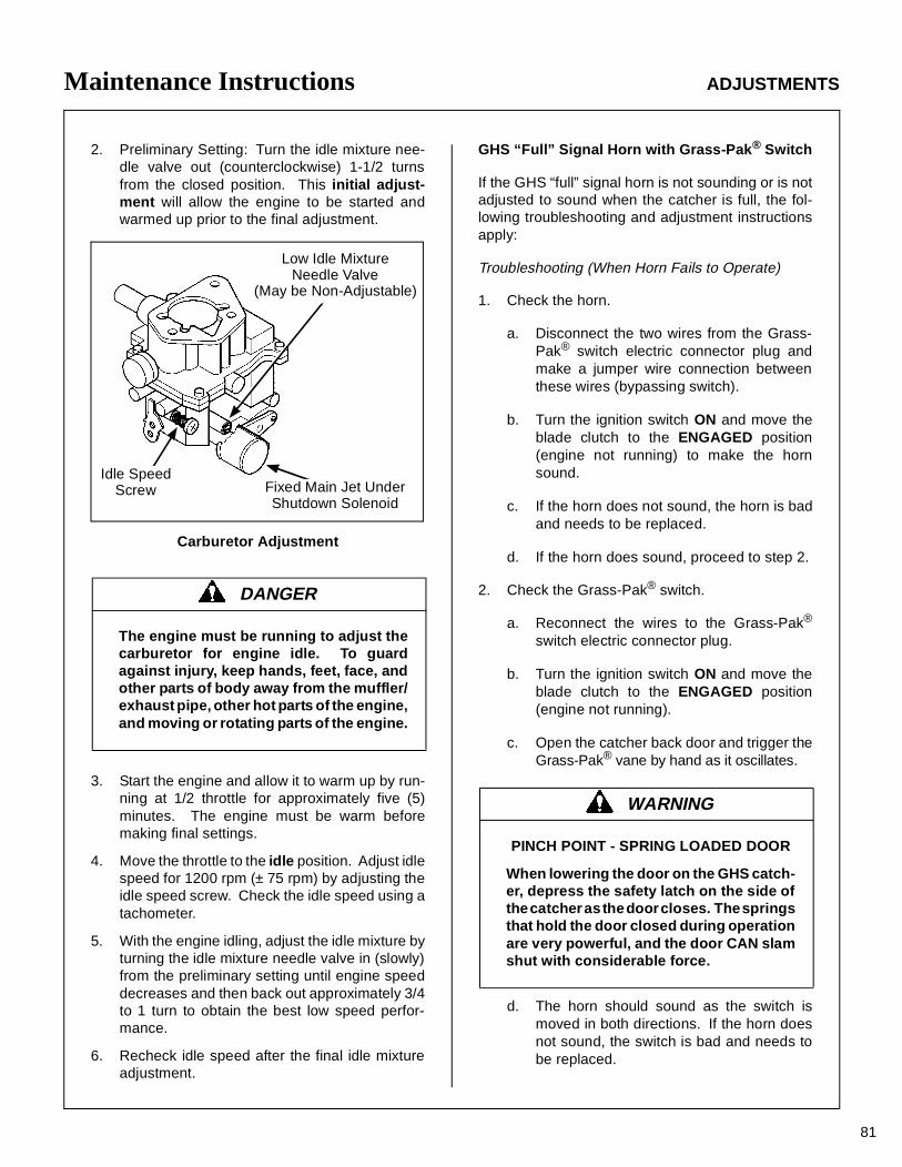
Maintenance Instructions ADJUSTMENTS
81
2. Preliminary Setting: Turn the idle mixture nee-dle valve out (counterclockwise) 1-1/2 turnsfrom the closed position. This initial adjust-ment will allow the engine to be started andwarmed up prior to the final adjustment.
Carburetor Adjustment
3. Start the engine and allow it to warm up by run-ning at 1/2 throttle for approximately five (5)minutes. The engine must be warm beforemaking final settings.
4. Move the throttle to the idle position. Adjust idlespeed for 1200 rpm (± 75 rpm) by adjusting theidle speed screw. Check the idle speed using atachometer.
5. With the engine idling, adjust the idle mixture byturning the idle mixture needle valve in (slowly)from the preliminary setting until engine speeddecreases and then back out approximately 3/4to 1 turn to obtain the best low speed perfor-mance.
6. Recheck idle speed after the final idle mixtureadjustment.
GHS “Full” Signal Horn with Grass-Pak ® Switch
If the GHS “full” signal horn is not sounding or is notadjusted to sound when the catcher is full, the fol-lowing troubleshooting and adjustment instructionsapply:
Troubleshooting (When Horn Fails to Operate)
1. Check the horn.
a. Disconnect the two wires from the Grass-Pak® switch electric connector plug andmake a jumper wire connection betweenthese wires (bypassing switch).
b. Turn the ignition switch ON and move theblade clutch to the ENGAGED position(engine not running) to make the hornsound.
c. If the horn does not sound, the horn is badand needs to be replaced.
d. If the horn does sound, proceed to step 2.
2. Check the Grass-Pak® switch.
a. Reconnect the wires to the Grass-Pak®
switch electric connector plug.
b. Turn the ignition switch ON and move theblade clutch to the ENGAGED position(engine not running).
c. Open the catcher back door and trigger theGrass-Pak® vane by hand as it oscillates.
d. The horn should sound as the switch ismoved in both directions. If the horn doesnot sound, the switch is bad and needs tobe replaced.
DANGER
The engine must be running to adjust thecarburetor for engine idle. To guardagainst injury, keep hands, feet, face, andother parts of body away from the muffler/exhaust pipe, other hot parts of the engine,and moving or rotating parts of the engine.
Low Idle MixtureNeedle Valve
(May be Non-Adjustable)
Fixed Main Jet UnderShutdown Solenoid
Idle SpeedScrew
WARNING
PINCH POINT - SPRING LOADED DOOR
When lowering the door on the GHS catch-er, depress the safety latch on the side ofthe catcher as the door closes. The springsthat hold the door closed during operationare very powerful, and the door CAN slamshut with considerable force.

82
Maintenance Instructions ADJUSTMENTS/ELECTRICAL SYSTEM
Checking the Grass-Pak® Switch
Adjustment (When Horn Sounds at the Wrong Time)
Very little, if any, adjustment to the Grass-Pak®
switch is required. However, to fine tune the timingof the full signal, the vertical position of the switchvane is adjustable approximately 3/4 in. (1.9 mm).
1. Loosen the screw mounting the vane on theswitch and adjust the position of the vane as fol-lows:
a. Move the vane UP to delay the signal.
b. Move vane DOWN to advance the signal.
2. Retighten the screw.
NOTE: It will not be possible to adjust the switch togive a signal at the precise instant the catcher is fullfor a wide variety of mowing conditions. For exam-ple, wet heavy grass will fill the catcher differentlythan dry, fluffy grass, causing the signal to come ona little sooner or later than usual. Primarily, theswitch should be adjusted to give the “full” signalwith a little advance warning before overfillingand clogging of the grass delivery chute begins (re-gardless of mowing conditions).
Grass-Pak® Switch Vane Adjustment
ELECTRICAL SYSTEM
For troubleshooting, refer to Wiring Diagram.
IMPORTANT: Disconnect both battery cables be-fore unplugging any wiring connectors or making re-pairs on the electrical system.
IMPORTANT: Disconnect the battery cables beforeunplugging and removing the instrument panel.
Circuit Breakers
A master circuit breaker is mounted on a bracket be-hind the battery. The circuit breaker may have eitherthe manual or automatic reset function -- both typeshave been used. See Circuit Breaker Locationphoto.
Circuit Breaker Location
WARNING
DO NOT test the Grass-Pak® switch withthe engine running. Projectiles CAN bethrown out of the grass delivery spout andCAN cause serious injury to bystanders orproperty damage.
Grass-Pak®
Vane Switch
Advance
AdjustmentScrew
Delay
30 AmpCircuit Breaker
Circuit BreakerMounting Bracket
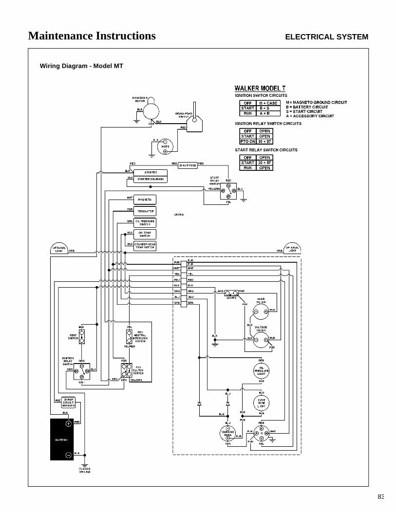
83
Maintenance Instructions ELECTRICAL SYSTEM
Wiring Diagram - Model MT

84
Operator’s Notes

85
Operator’s Notes

86
Operator’s Notes

87
LIMITED WARRANTYFOR
WALKERCOMMERCIAL RIDER MOWER
1. WHAT THIS WARRANTY COVERS, AND FOR HOW LONG:
Walker Manufacturing company will, at its option, repair or replace, without charge, any part covered by this warrantywhich is found to be defective in material and/or workmanship within one (1) year* after date of sale to the original retailpurchaser unless the product is used for rental purposes, in which case this warranty is limited to ninety (90) days. AtWalker’s request, customer will make the defective part available for inspection by Walker and/or return the defective partto Walker, transportation charges prepaid. All parts and components of the Walker Mower are covered by this warrantyexcept the following components which are warranted separately by their respective manufacturers:
Kohler EngineKubota EngineKawasaki EngineEaton Hydraulic TransmissionPeerless GearboxesBatteryTires
The available warranties covering these items are furnished with each mower. Walker does not assume any warranty obli-gation, liability or modification for these items, which are covered exclusively by the stated warranty of the respective man-ufacturers noted above.
* An extended three (3) year warranty is offered on the Walker P/N 6200 Gear Axle Assembly.
2. WHAT THIS WARRANTY DOES NOT COVER:
A. This warranty does not cover defects caused by depreciation or damage caused by normal wear, accidents, impropermaintenance, improper use or abuse of the product, alterations, or failure to follow the instructions contained in theOwner’s Manual for operation and maintenance.
B. The customer shall pay any charges for making service calls and/or for transporting the mower to and from the placewhere the inspection and/or warranty work is performed.
3. HOW TO OBTAIN SERVICE UNDER THIS WARRANTY:
Warranty service can be arranged by contacting the dealer where you purchased the mower or by contacting Walker Man-ufacturing Company, 5925 East Harmony Road, Ft. Collins, CO 80528. Proof of the date of purchase may be required toverify warranty coverage.
4. WARRANTY LIMITATION:
A. THERE IS NO OTHER EXPRESS WARRANTY. ANY WARRANTY THAT MAY BE IMPLIED FROM THISPURCHASE INCLUDING MERCHANTABILITY AND FITNESS FOR A PARTICULAR PURPOSE IS HEREBYLIMITED TO THE DURATION OF THIS WARRANTY AND TO THE EXTENT PERMITTED BY LAW ANY AND ALLIMPLIED WARRANTIES ARE EXCLUDED. Some states do not allow limitations on how long an implied warrantylasts, so the above limitations may not apply to you.
B. WALKER WILL NOT BE LIABLE FOR ANY INCIDENTAL, CONSEQUENTIAL, OR SPECIAL DAMAGES AND/OREXPENSES IN CONNECTION WITH THE PURCHASE OR USE OF THE MOWER. Some states do not allow theexclusion or limitation of incidental or consequential damages, so the above limitation(s) or exclusion(s) may notapply to you.
C. Only the warranty expressed in this limited warranty shall apply and no dealer, distributor, or individual is authorizedto amend, modify, or extend this warranty in any way. Accordingly, additional statements such as dealer advertisingor presentations, whether oral or written, do not constitute warranties by Walker, and should not be relied upon.
D. This warranty gives you specific legal rights, and you may also have other rights which vary from state to state.

WALKER MFG. CO. • 5925 E. HARMONY ROAD, FORT COLLINS, CO 80528 • (970) 221-5614FORM NO. 101298 PRINTED IN USA ©1998 WALKER MFG. CO
Sound - Model MT20
Sound Test
Sound test conducted was in accordance with 79/113/EEC and was performed on 22 March 96 under the conditions listed:
General Condition: Clear
Temperature: 50 (F)o10 (C)o
Wind Speed: < 5 mph (< 8 kmh)
Humidity: 52%
Barometric Pressure: 24.9" HG (759 mm Hg)
Lwa104
LpA96
OPERATOR
Sound - Model MT25
Vibration - Model MT20 Vibration - Model MT25
Vibration Level
Vibration levels at the operators handles were measured in the vertical, lateral, and longitudinal directions using calibrated vibra-tion test equipment.
Tests were performed on 22 March 96 under the conditions listed:
0.7g
Sound Test
Sound test conducted was in accordance with 79/113/EEC and was performed on 22 March 96 under the conditions listed:
Lwa106
LpA95
OPERATOR
General Condition: Clear
Temperature: 50 (F)o10 (C)o
Wind Speed: < 5 mph (< 8 kmh)
Humidity: 52%
Barometric Pressure: 24.9" HG (759 mm Hg)
Vibration Level
Vibration levels at the operators handles were measured in the vertical, lateral, and longitudinal directions using calibrated vibra-tion test equipment.
Tests were performed on 22 March 96 under the conditions listed:
0.8g
General Condition: Clear
Temperature: 50 (F)o10 (C)o
Wind Speed: < 5 mph (< 8 kmh)
Humidity: 52%
Barometric Pressure: 24.9" HG (759 mm Hg)
General Condition: Clear
Temperature: 50 (F)o10 (C)o
Wind Speed: < 5 mph (< 8 kmh)
Humidity: 52%
Barometric Pressure: 24.9" HG (759 mm Hg)
General Condition: Clear
Temperature: 50 (F)o10 (C)o
Wind Speed: < 5 mph (< 8 kmh)
Humidity: 52%
Barometric Pressure: 24.9" HG (759 mm Hg)