overview of mechanical engineering for non-mes part 1: statics 3 rigid bodies i: equivalent systems...
TRANSCRIPT

Overview of Mechanical Engineering for Non-MEsPart 1: Statics3 Rigid Bodies I:
Equivalent Systems of Forces

Overview of Mechanical Engineering
3 - 2
Contents
Introduction
External and Internal Forces
Principle of Transmissibility: Equivalent Forces
Vector Products of Two Vectors
Moment of a Force About a Point
Varigon’s Theorem
Rectangular Components of the Moment of a Force
Sample Problem 3.1
Scalar Product of Two Vectors
Scalar Product of Two Vectors: Applications
Mixed Triple Product of Three Vectors
Moment of a Force About a Given Axis
Sample Problem 3.5
Moment of a Couple
Addition of Couples
Couples Can Be Represented By Vectors
Resolution of a Force Into a Force at O and a Couple
Sample Problem 3.6
System of Forces: Reduction to a Force and a Couple
Further Reduction of a System of Forces
Sample Problem 3.8
Sample Problem 3.10

Overview of Mechanical Engineering
3 - 3
Introduction• Treatment of a body as a single particle is not always possible. In
general, the size of the body and the specific points of application of the forces must be considered.
• Most bodies in elementary mechanics are assumed to be rigid, i.e., the actual deformations are small and do not affect the conditions of equilibrium or motion of the body (deformable body will be considered in Chapter ??).
• Current chapter describes the effect of forces exerted on a rigid body and how to replace a given system of forces with a simpler equivalent system.
• moment of a force about a point
• moment of a force about an axis
• moment due to a couple
• Any system of forces acting on a rigid body can be replaced by an equivalent system consisting of one force acting at a given point and one couple.
Overview of Mechanical Engineering
3 - 4
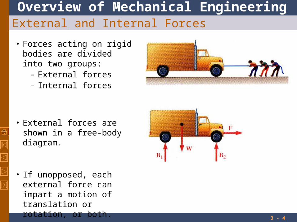
External and Internal Forces
• Forces acting on rigid bodies are divided into two groups:
- External forces- Internal forces
• External forces are shown in a free-body diagram.
• If unopposed, each external force can impart a motion of translation or rotation, or both.
Overview of Mechanical Engineering
3 - 5
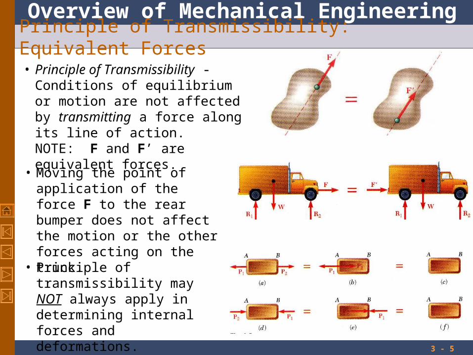
Principle of Transmissibility: Equivalent Forces
• Principle of Transmissibility -Conditions of equilibrium or motion are not affected by transmitting a force along its line of action.NOTE: F and F’ are equivalent forces.
• Moving the point of application of the force F to the rear bumper does not affect the motion or the other forces acting on the truck.
• Principle of transmissibility may NOT always apply in determining internal forces and deformations.
Overview of Mechanical Engineering
3 - 6
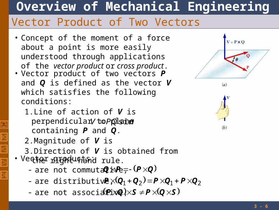
Vector Product of Two Vectors• Concept of the moment of a force about a point is
more easily understood through applications of the vector product or cross product.
• Vector product of two vectors P and Q is defined as the vector V which satisfies the following conditions:1. Line of action of V is perpendicular to plane
containing P and Q.2. Magnitude of V is3. Direction of V is obtained from the right-hand
rule.
sinQPV
• Vector products:
- are not commutative,
- are distributive,
- are not associative,
QPPQ 2121 QPQPQQP
SQPSQP
Overview of Mechanical Engineering
3 - 7
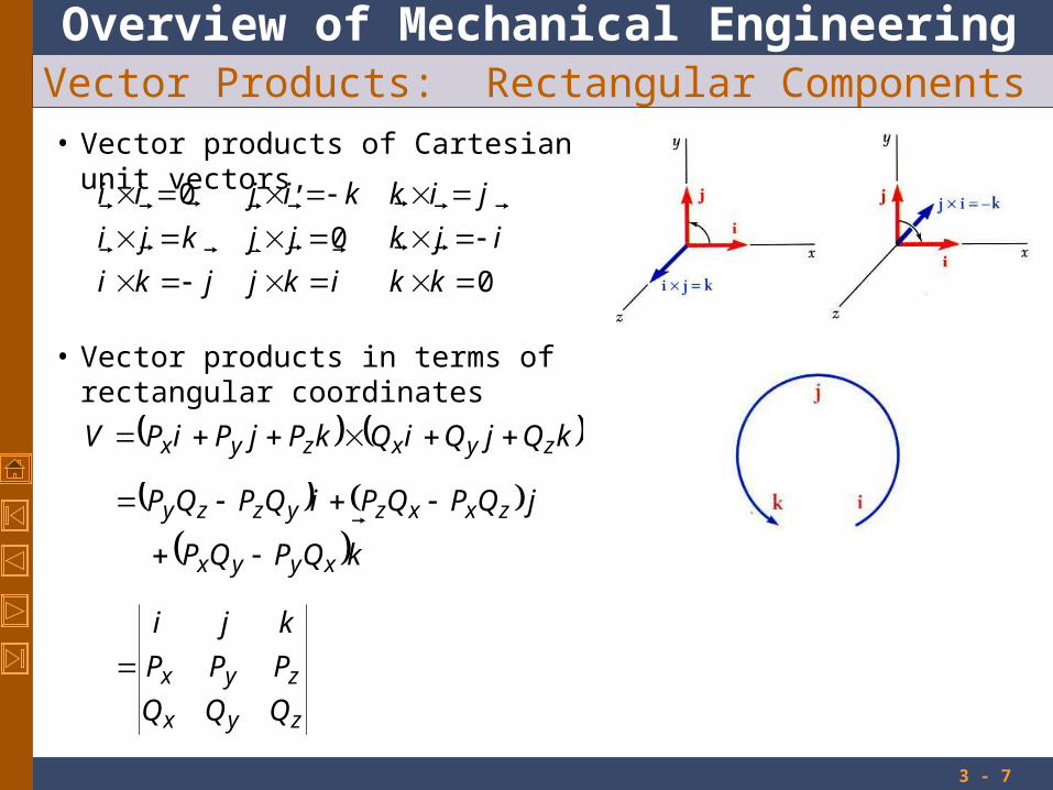
Vector Products: Rectangular Components• Vector products of Cartesian unit vectors,
0
0
0
kkikjjki
ijkjjkji
jikkijii
• Vector products in terms of rectangular coordinates
kQjQiQkPjPiPV zyxzyx
kQPQP
jQPQPiQPQP
xyyx
zxxzyzzy
zyx
zyx
QQQ
PPP
kji

Overview of Mechanical Engineering
3 - 8
Moment of a Force About a Point• A force vector is defined by its magnitude and
direction. Its effect on the rigid body also depends on it point of application.
• The moment of F about O is defined as
FrMO
• The moment vector MO is perpendicular to the plane containing O and the force F.
• Any force F’ that has the same magnitude and direction as F, is equivalent if it also has the same line of action and therefore, produces the same moment.
• Magnitude of MO measures the tendency of the force to cause rotation of the body about an axis along MO.
The sense of the moment may be determined by the right-hand rule.
FdrFMO sin
Overview of Mechanical Engineering
3 - 9
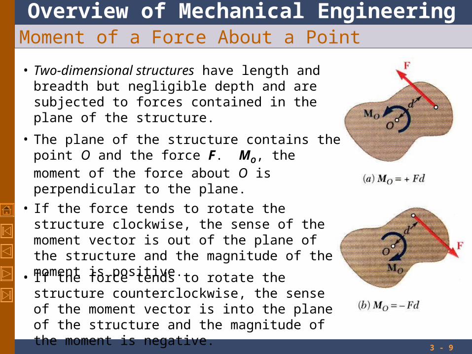
Moment of a Force About a Point
• Two-dimensional structures have length and breadth but negligible depth and are subjected to forces contained in the plane of the structure.
• The plane of the structure contains the point O and the force F. MO, the moment of the force about O is perpendicular to the plane.
• If the force tends to rotate the structure clockwise, the sense of the moment vector is out of the plane of the structure and the magnitude of the moment is positive.
• If the force tends to rotate the structure counterclockwise, the sense of the moment vector is into the plane of the structure and the magnitude of the moment is negative.

Overview of Mechanical Engineering
3 - 10
Varignon’s Theorem
• The moment about a give point O of the resultant of several concurrent forces is equal to the sum of the moments of the various moments about the same point O.
• Varigon’s Theorem makes it possible to replace the direct determination of the moment of a force F by the moments of two or more component forces of F.
2121 FrFrFFr
Overview of Mechanical Engineering
3 - 11
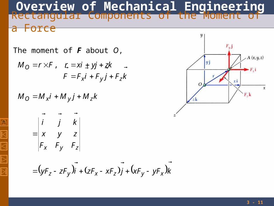
Rectangular Components of the Moment of a Force
kyFxFjxFzFizFyF
FFF
zyx
kji
kMjMiMM
xyzxyz
zyx
zyxO
The moment of F about O,
kFjFiFF
kzjyixrFrM
zyx
O
,
Overview of Mechanical Engineering
3 - 12
Rectangular Components of the Moment of a Force
The moment of F about B,
FrM BAB
/
kFjFiFF
kzzjyyixx
rrr
zyx
BABABA
BABA
/
zyx
BABABAB
FFF
zzyyxx
kji
M

Overview of Mechanical Engineering
3 - 13
Rectangular Components of the Moment of a Force
For two-dimensional structures,
zy
ZO
zyO
yFxF
MM
kyFxFM
zBAyBA
ZO
zBAyBAO
FyyFxx
MM
kFyyFxxM
Overview of Mechanical Engineering
3 - 14
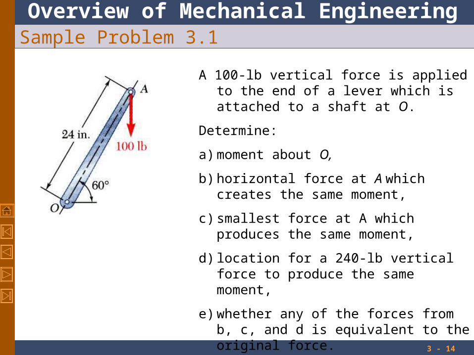
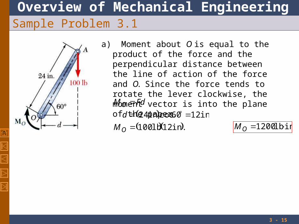
Sample Problem 3.1
A 100-lb vertical force is applied to the end of a lever which is attached to a shaft at O.
Determine:
a) moment about O,
b) horizontal force at A which creates the same moment,
c) smallest force at A which produces the same moment,
d) location for a 240-lb vertical force to produce the same moment,
e) whether any of the forces from b, c, and d is equivalent to the original force.
Overview of Mechanical Engineering
3 - 15
Sample Problem 3.1
a) Moment about O is equal to the product of the force and the perpendicular distance between the line of action of the force and O. Since the force tends to rotate the lever clockwise, the moment vector is into the plane of the paper.
in. 12lb 100
in. 1260cosin.24
O
O
M
d
FdM
in lb 1200 OM
Overview of Mechanical Engineering
3 - 16
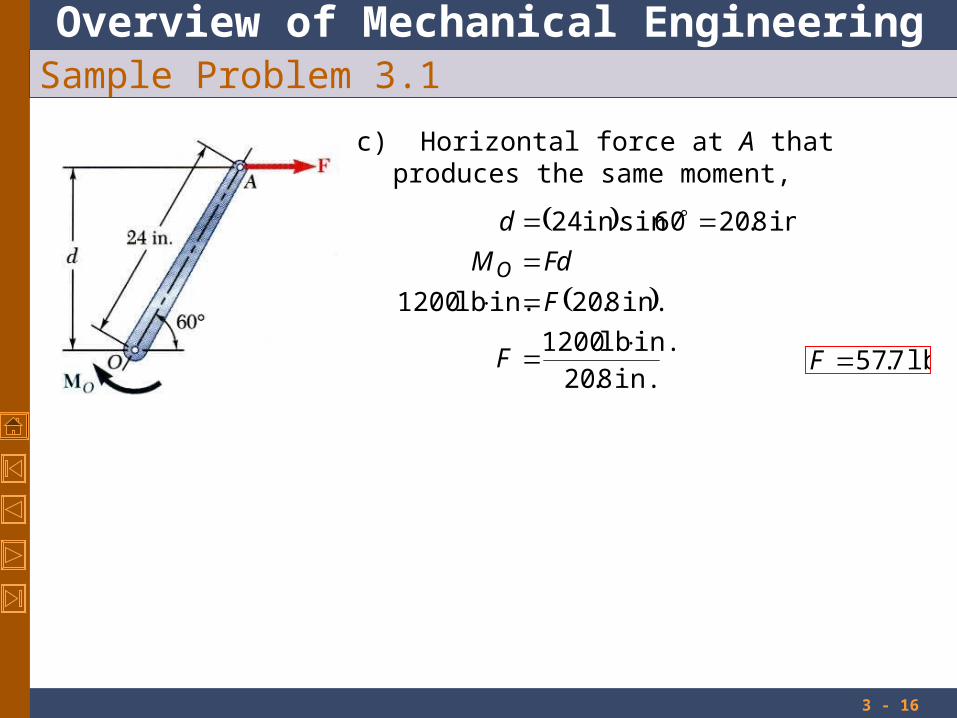
Sample Problem 3.1
c) Horizontal force at A that produces the same moment,
in. 8.20
in. lb 1200
in. 8.20in. lb 1200
in. 8.2060sinin. 24
F
F
FdM
d
O
lb 7.57F

Overview of Mechanical Engineering
3 - 17
Sample Problem 3.1
c) The smallest force A to produce the same moment occurs when the perpendicular distance is a maximum or when F is perpendicular to OA.
in. 42
in. lb 1200
in. 42in. lb 1200
F
F
FdMO
lb 50F
Overview of Mechanical Engineering
3 - 18
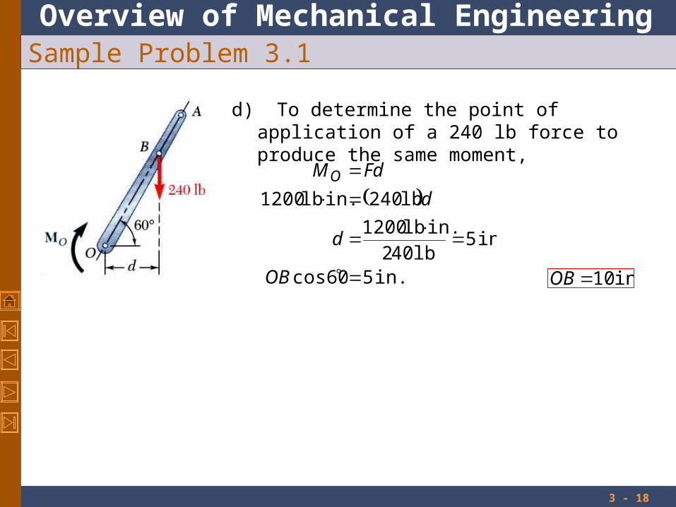
Sample Problem 3.1
d) To determine the point of application of a 240 lb force to produce the same moment,
in. 5cos60
in. 5lb 402
in. lb 1200
lb 240in. lb 1200
OB
d
d
FdMO
in. 10OB

Overview of Mechanical Engineering
3 - 19
Sample Problem 3.1
e) Although each of the forces in parts b), c), and d) produces the same moment as the 100 lb force, none are of the same magnitude and sense, or on the same line of action. None of the forces is equivalent to the 100 lb force.

Overview of Mechanical Engineering
3 - 20
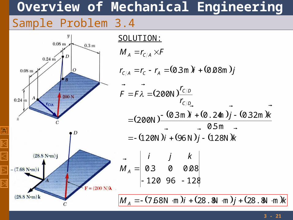
Sample Problem 3.4
The rectangular plate is supported by the brackets at A and B and by a wire CD. Knowing that the tension in the wire is 200 N, determine the moment about A of the force exerted by the wire at C.
SOLUTION:
The moment MA of the force F exerted by the wire is obtained by evaluating the vector product,
FrM ACA
Overview of Mechanical Engineering
3 - 21
Sample Problem 3.4SOLUTION:
12896120
08.003.0
kji
M A
kjiM A
mN 8.82mN 8.82mN 68.7
jirrr ACAC
m 08.0m 3.0
FrM ACA
kji
kji
r
rFF
DC
DC
N 128N 69N 120
m 5.0
m 32.0m 0.24m 3.0N 200
N 200
Overview of Mechanical Engineering
3 - 22
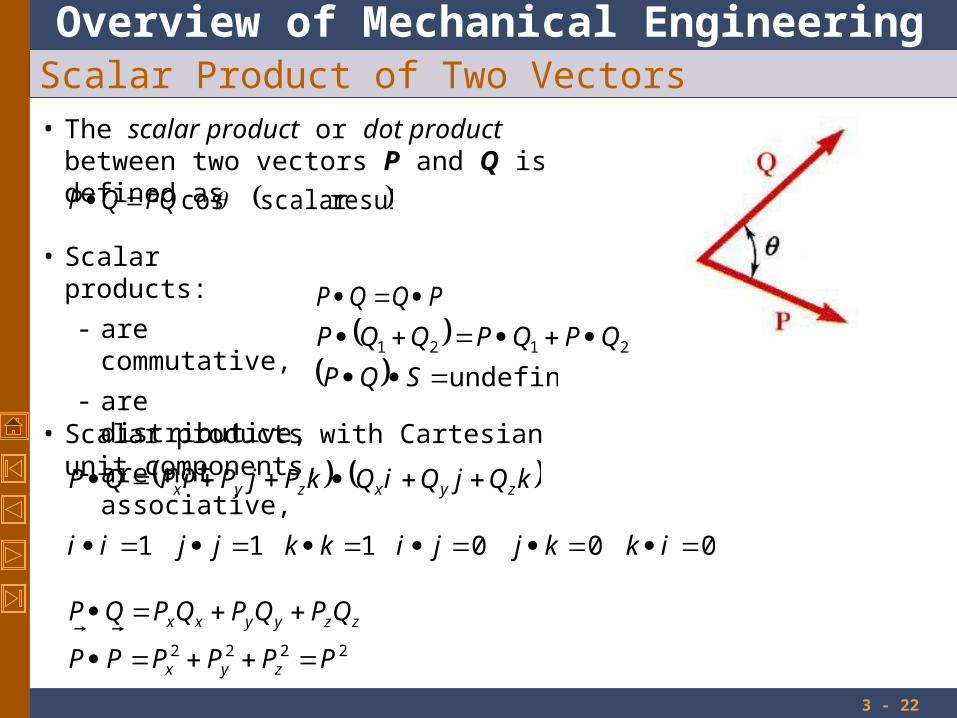
Scalar Product of Two Vectors• The scalar product or dot product between
two vectors P and Q is defined as
resultscalarcosPQQP
• Scalar products:
- are commutative,
- are distributive,
- are not associative,
PQQP
2121 QPQPQQP
undefined SQP
• Scalar products with Cartesian unit components,
000111 ikkjjikkjjii
kQjQiQkPjPiPQP zyxzyx
2222 PPPPPP
QPQPQPQP
zyx
zzyyxx

Overview of Mechanical Engineering
3 - 23
Scalar Product of Two Vectors: Applications
• Angle between two vectors:
PQ
QPQPQP
QPQPQPPQQP
zzyyxx
zzyyxx
cos
cos
• Projection of a vector on a given axis:
OL
OL
PPQ
QP
PQQP
OLPPP
cos
cos
along of projection cos
zzyyxx
OL
PPP
PP
coscoscos
• For an axis defined by a unit vector:
Overview of Mechanical Engineering
3 - 24
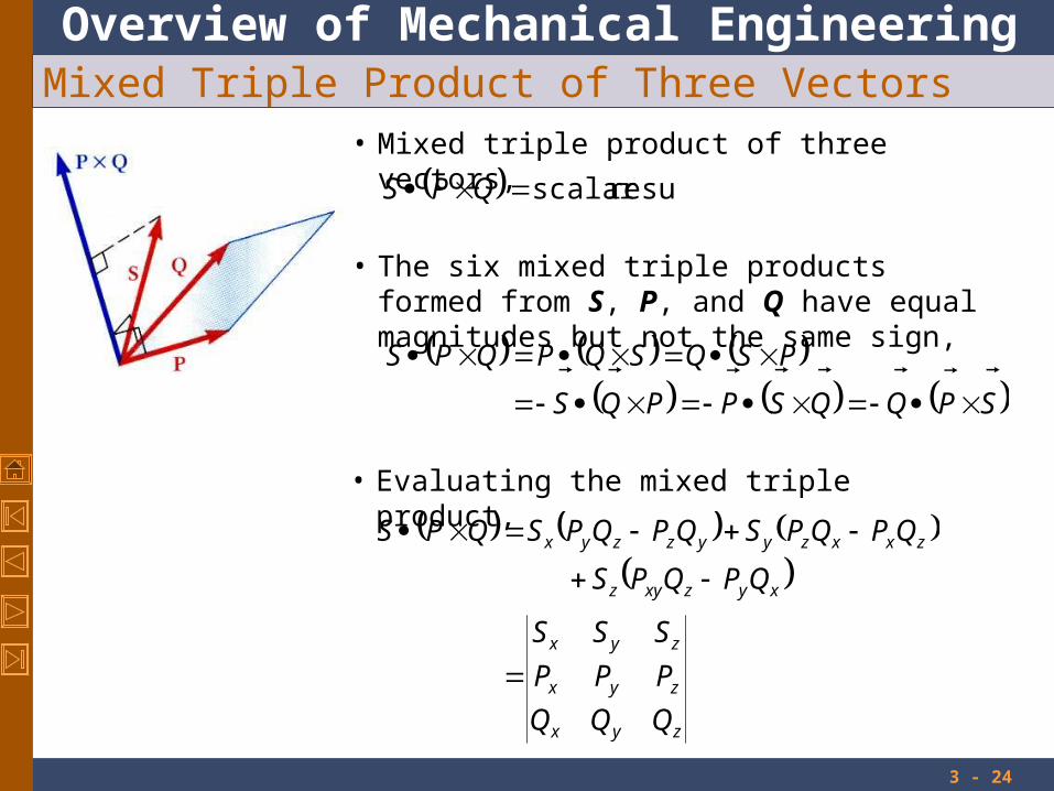
Mixed Triple Product of Three Vectors• Mixed triple product of three vectors,
resultscalar QPS
• The six mixed triple products formed from S, P, and Q have equal magnitudes but not the same sign,
SPQQSPPQS
PSQSQPQPS
zyx
zyx
zyx
xyzxyz
zxxzyyzzyx
QQQ
PPP
SSS
QPQPS
QPQPSQPQPSQPS
• Evaluating the mixed triple product,
Overview of Mechanical Engineering
3 - 25
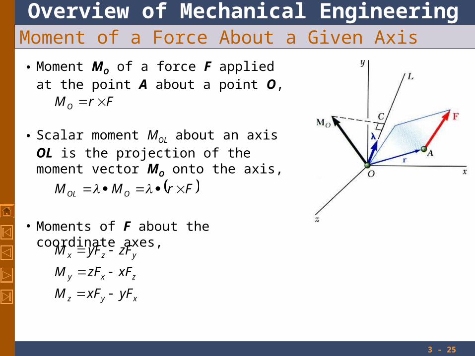
Moment of a Force About a Given Axis
• Moment MO of a force F applied at the point A about a point O,
FrM O
• Scalar moment MOL about an axis OL is the projection of the moment vector MO onto the axis,
FrMM OOL
• Moments of F about the coordinate axes,
xyz
zxy
yzx
yFxFM
xFzFM
zFyFM

Overview of Mechanical Engineering
3 - 26
Moment of a Force About a Given Axis
• Moment of a force about an arbitrary axis,
BABA
BA
BBL
rrr
Fr
MM
• The result is independent of the point B along the given axis.

Overview of Mechanical Engineering
3 - 27
Sample Problem 3.5
a) about A
b) about the edge AB and
c) about the diagonal AG of the cube.
d) Determine the perpendicular distance between AG and FC.
A cube is acted on by a force P as shown. Determine the moment of P

Overview of Mechanical Engineering
3 - 28
Sample Problem 3.5
• Moment of P about A,
jiPjiaM
jiPjiPP
jiajaiar
PrM
A
AF
AFA
2
222
kjiaPM A
2
• Moment of P about AB,
kjiaPi
MiM AAB
2
2aPM AB

Overview of Mechanical Engineering
3 - 29
Sample Problem 3.5
• Moment of P about the diagonal AG,
1116
23
12
3
1
3
aP
kjiaP
kjiM
kjiaP
M
kjia
kajaia
r
r
MM
AG
A
GA
GA
AAG
6
aPM AG

Overview of Mechanical Engineering
3 - 30
Sample Problem 3.5
• Perpendicular distance between AG and FC,
0
11063
1
2
Pkjikj
PP
Therefore, P is perpendicular to AG.
PdaP
M AG 6
6
ad
Overview of Mechanical Engineering
3 - 31
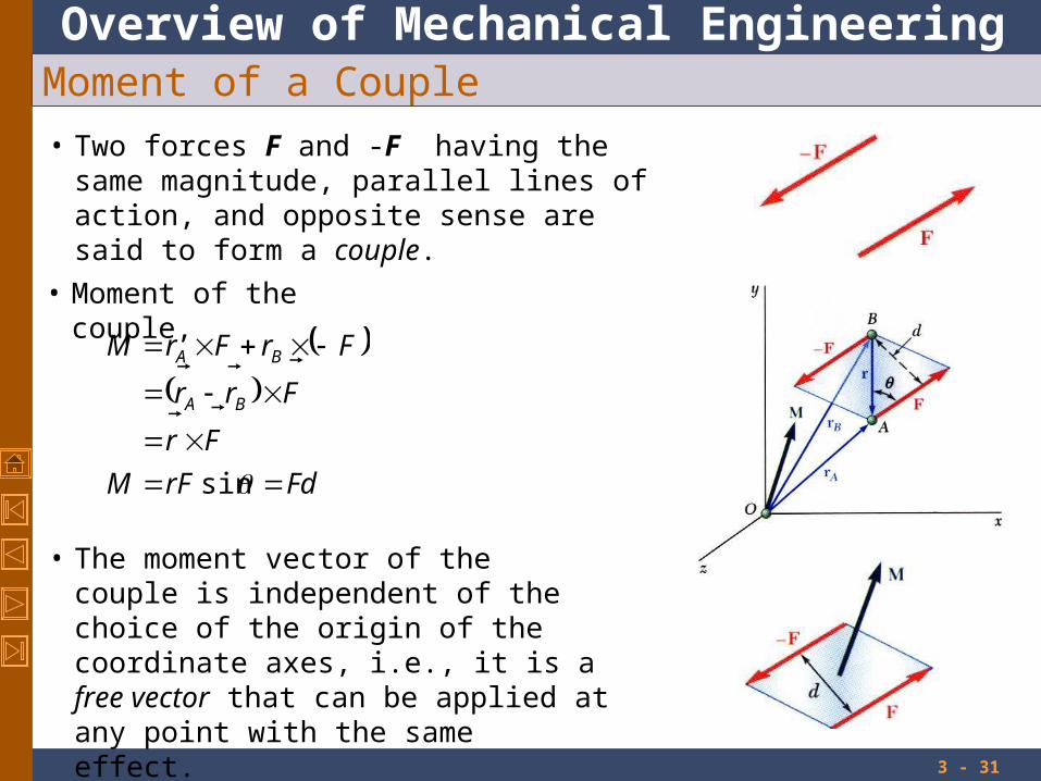
Moment of a Couple
• Two forces F and -F having the same magnitude, parallel lines of action, and opposite sense are said to form a couple.
• Moment of the couple,
FdrFM
Fr
Frr
FrFrM
BA
BA
sin
• The moment vector of the couple is independent of the choice of the origin of the coordinate axes, i.e., it is a free vector that can be applied at any point with the same effect.

Overview of Mechanical Engineering
3 - 32
Moment of a Couple
Two couples will have equal moments if
• 2211 dFdF
• the two couples lie in parallel planes, and
• the two couples have the same sense or the tendency to cause rotation in the same direction.

Overview of Mechanical Engineering
3 - 33
Addition of Couples
• Consider two intersecting planes P1 and P2 with each containing a couple
222
111
planein
planein
PFrM
PFrM
• Resultants of the vectors also form a couple
21 FFrRrM
• By Varigon’s theorem
21
21
MM
FrFrM
• Sum of two couples is also a couple that is equal to the vector sum of the two couples

Overview of Mechanical Engineering
3 - 34
Couples Can Be Represented by Vectors
• A couple can be represented by a vector with magnitude and direction equal to the moment of the couple.
• Couple vectors obey the law of addition of vectors.
• Couple vectors are free vectors, i.e., the point of application is not significant.
• Couple vectors may be resolved into component vectors.