overview of intermediate-temperature solid oxide fuel cells
TRANSCRIPT
Chapter 2
Overview of Intermediate-Temperature Solid
Oxide Fuel Cells
Harumi Yokokawa
2.1 Introduction
The first breakthrough in solid oxide fuel cell (SOFC) technology was achieved
by Westinghouse Power Corporation (WHPC; currently Siemens Power Gen-
eration Corporation) [1] in the late 1980s in their efforts in establishing tubular
SOFCs with the following technologically important points:
1. Optimizing the materials [yttrium-stabilized zirconia (YSZ) for the electro-lyte, lanthanum strontium manganite for the cathode, nickel for the anode,and lanthanum magnesium chromite for the interconnect].
2. Adopting an excellent processing technology of electrochemical vapordeposition (EVD) [2] that has extraordinary advantages in fabricatingdense films on porous materials or in anchoring nickel on YSZ.
3. Adopting a sealless tubular stack design to avoid usage of sealant materials.4. Aiming for stationary applications.
This breakthrough leveraged up the development of the SOFC stacks/
systems from the R&D stage to a more realistic stage with specifically targeted
market sectors. The long operation life was successfully demonstrated, and also
the high conversion efficiency from natural gas to electricity was demonstrated as
47% Lower Heating Value (LHV) for stationary 100-kW SOFC systems and as
52% for combined SOFC-gas turbine systems.Immediately after the first breakthrough with sealless tubular cells, detailed
analyses were made by Ackerman at the Argonne National Laboratory (ANL)
to identify the merits and demerits of the sealless tubular cells [3]. The main
disadvantages were pointed out as follows:
H. Yokokawa (*)Energy Technology Research Institute, National Institute of Advanced IndustrialScience and Technology, Higashi 1-1-1, AIST Central No.5, Tsukuba, Ibaraki305-8565, Japane-mail: [email protected]
T. Ishihara (ed.), Perovskite Oxide for Solid Oxide Fuel Cells,Fuel Cells and Hydrogen Energy, DOI 10.1007/978-0-387-77708-5_2,� Springer ScienceþBusiness Media, LLC 2009
17
1. High fabrication costs because the EVD process utilizes metal chloridevapors in vacuum.
2. Low volumetric power densities because the electrical paths lie transverselyalong the cathode layer in tubular cells.
Since then, various attempts [4–6] have been made to investigate the follow-ing main points:
1. Planar cells to improve the power density.2. Tubular cells to lower the fabrication cost or to increase the power density.
The next new wave in developing solid oxide fuel cells arose around themid-1990s. One of the biggest achievements in this period was the discovery of anew oxide ion conductor, namely, lanthanum strontium gallium magnesiumoxides (LSGM), by Ishihara in 1994 [7, 8]. Another important impact on SOFCtechnology was the proposal of using SOFCs as auxiliary power units forautomotive applications by BMW and Delphi [9]. A similar proposal wasmade by ANL for monolithic SOFCs in the late 1980s [10] in their efforts toovercome the demerits of sealless tubular cells. Even so, the proposal by BMW/Delphi was based on the important trends in recent SOFC technology develop-ment; that is, lowering the operational temperature for using metal intercon-nects. In view of this, the discovery of a new electrolyte has further facilitatedthis trend.
Quite recently, a small SOFC system for residential application has beenconstructed by Kyocera and tested by Osaka Gas [11]. These test resultsindicate surprisingly high stack efficiencies, more than 50% Higher HeatingValue (HHV) during the steady-state operation and 42%–48% LHV as theaveraged system net efficiency over a 24-h service period in a residential house.Similarly, Mitsubishi Materials Corporation and The Kansai Electric PowerCo., Inc. also achieved high conversion efficiencies by using a Co-doped LSGM(LSGMC) electrolyte. These achievements indicate that the development stageof the SOFC technology is apparently being stepped up and that a new era ofSOFC developments has already started. The important key word for this newera is the ‘‘intermediate-temperature SOFCs.’’ In this chapter, these recent devel-opments associated with the intermediate-temperature SOFCs are reviewed withan emphasis on the stack/system development.
2.2 Characteristic Features of Solid Oxide Fuel Cells
2.2.1 Merits and Demerits of SOFCs
Solid oxide fuel cells make use of the high-temperature oxides as electrolyte.Figure 2.1 compares the conductivities of common electrolytes that are utilizedin various fuel cells; namely, phosphoric acid fuel cells (PAFC), polymerelectrolyte fuel cells (PEFC), molten carbonate fuel cells (MCFC), and solid
18 H. Yokokawa
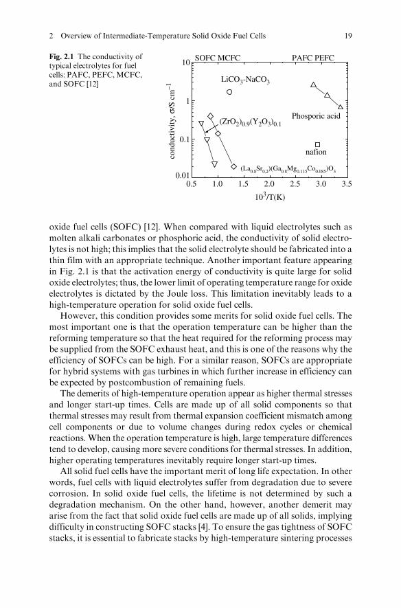
oxide fuel cells (SOFC) [12]. When compared with liquid electrolytes such as
molten alkali carbonates or phosphoric acid, the conductivity of solid electro-
lytes is not high; this implies that the solid electrolyte should be fabricated into a
thin film with an appropriate technique. Another important feature appearing
in Fig. 2.1 is that the activation energy of conductivity is quite large for solidoxide electrolytes; thus, the lower limit of operating temperature range for oxide
electrolytes is dictated by the Joule loss. This limitation inevitably leads to a
high-temperature operation for solid oxide fuel cells.However, this condition provides some merits for solid oxide fuel cells. The
most important one is that the operation temperature can be higher than the
reforming temperature so that the heat required for the reforming process may
be supplied from the SOFC exhaust heat, and this is one of the reasons why the
efficiency of SOFCs can be high. For a similar reason, SOFCs are appropriate
for hybrid systems with gas turbines in which further increase in efficiency can
be expected by postcombustion of remaining fuels.The demerits of high-temperature operation appear as higher thermal stresses
and longer start-up times. Cells are made up of all solid components so that
thermal stresses may result from thermal expansion coefficient mismatch among
cell components or due to volume changes during redox cycles or chemical
reactions. When the operation temperature is high, large temperature differences
tend to develop, causing more severe conditions for thermal stresses. In addition,
higher operating temperatures inevitably require longer start-up times.All solid fuel cells have the important merit of long life expectation. In other
words, fuel cells with liquid electrolytes suffer from degradation due to severe
corrosion. In solid oxide fuel cells, the lifetime is not determined by such a
degradation mechanism. On the other hand, however, another demerit may
arise from the fact that solid oxide fuel cells are made up of all solids, implying
difficulty in constructing SOFC stacks [4]. To ensure the gas tightness of SOFC
stacks, it is essential to fabricate stacks by high-temperature sintering processes
0.5 1.0 1.5 2.0 2.5 3.0 3.50.01
0.1
1
10
(La0.8Sr0.2)(Ga0.8Mg0.115Co0.085)O3
PEFCPAFCMCFCSOFC
nafion
Phosporic acid
LiCO3-NaCO3
(ZrO2)0.9(Y2O3)0.1
cond
uctiv
ity, σ
/S c
m–1
103/T(K)
Fig. 2.1 The conductivity oftypical electrolytes for fuelcells: PAFC, PEFC,MCFC,and SOFC [12]
2 Overview of Intermediate-Temperature Solid Oxide Fuel Cells 19
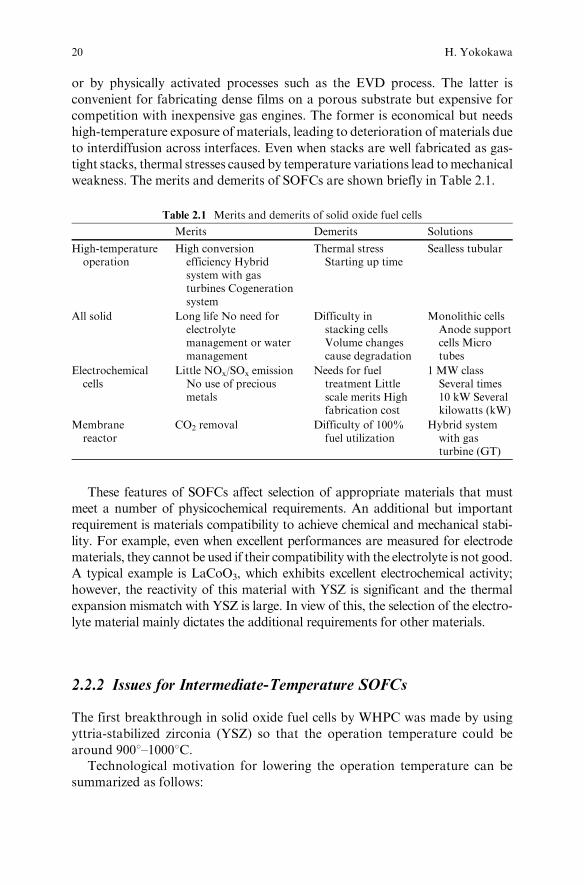
or by physically activated processes such as the EVD process. The latter is
convenient for fabricating dense films on a porous substrate but expensive for
competition with inexpensive gas engines. The former is economical but needs
high-temperature exposure of materials, leading to deterioration of materials due
to interdiffusion across interfaces. Even when stacks are well fabricated as gas-
tight stacks, thermal stresses caused by temperature variations lead tomechanical
weakness. The merits and demerits of SOFCs are shown briefly in Table 2.1.
These features of SOFCs affect selection of appropriate materials that must
meet a number of physicochemical requirements. An additional but important
requirement is materials compatibility to achieve chemical and mechanical stabi-
lity. For example, even when excellent performances are measured for electrode
materials, they cannot be used if their compatibility with the electrolyte is not good.
A typical example is LaCoO3, which exhibits excellent electrochemical activity;
however, the reactivity of this material with YSZ is significant and the thermal
expansion mismatch with YSZ is large. In view of this, the selection of the electro-
lyte material mainly dictates the additional requirements for other materials.
2.2.2 Issues for Intermediate-Temperature SOFCs
The first breakthrough in solid oxide fuel cells by WHPC was made by using
yttria-stabilized zirconia (YSZ) so that the operation temperature could be
around 9008–10008C.Technological motivation for lowering the operation temperature can be
summarized as follows:
Table 2.1 Merits and demerits of solid oxide fuel cells
Merits Demerits Solutions
High-temperatureoperation
High conversionefficiency Hybridsystem with gasturbines Cogenerationsystem
Thermal stressStarting up time
Sealless tubular
All solid Long life No need forelectrolytemanagement or watermanagement
Difficulty instacking cellsVolume changescause degradation
Monolithic cellsAnode supportcells Microtubes
Electrochemicalcells
Little NOx/SOx emissionNo use of preciousmetals
Needs for fueltreatment Littlescale merits Highfabrication cost
1 MW classSeveral times10 kW Severalkilowatts (kW)
Membranereactor
CO2 removal Difficulty of 100%fuel utilization
Hybrid systemwith gasturbine (GT)
20 H. Yokokawa
1. In the beginning, strong interest arose in utilization of metal interconnectsinstead of LaCrO3-based oxide interconnects [13]. Because of the severecorrosion of metals at high temperatures, operation temperature needs tobe lowered.
2. Thermodynamic conversion efficiency increases with decreasing tempera-ture for reformed gas (a mixture of CO and hydrogen).
3. Sealing technique becomes less difficult with lowered temperature.4. For a small system, radiation heat loss becomes less severe by decreasing
temperature. Hence, heat management becomes easier at lower tempera-tures [11].
On the other hand, decreasing operation temperature gives rise to additionalmaterials issues as follows:
1. The oxide ionic conductivity decreases rapidly with decreasing temperature.As indicated in Fig. 2.1, the activation energy for the ionic conductivity ishigh so that the ionic conductivity drop is rather significant. To establishintermediate-temperature SOFCs, it is essential to have faster oxide ionconductors or to have a good method of fabricating a thinner electrolytefilm. In view of these concerns, anode-supported cells are one of the possibletechnological solutions.
2. Usually, the electrode activity also decreases drastically with decreasingtemperature, which makes it necessary to utilize more active electrodematerials.
3. For the anode, nickel is still the best choice for operation in the intermediate-temperature region. Most frequently observed effects on nickel anodes aresulfur poisoning. It is well known that degradation caused by hydrogensulfide becomes more severe with decreasing temperature.
4. For the cathode, Cr poisoning is severe on the lanthanum strontium manga-nites and becomes worse with decreasing temperature, against expectations.
In what follows, the materials aspects of intermediate-temperature SOFCsare described.
2.2.2.1 Electrolytes and Conversion Efficiency
The conduction properties of electrolytes are the most important factors indetermining the operational temperature [11]. Here, the conversion efficiency isdescribed in terms of conduction properties. The oxide ion conductivity deter-mines the area-specific resistance contributed by the electrolyte. The contribu-tion increases with increasing thickness of the electrolyte plate (film).
The oxide ion conductivity exhibits an Arrhenius-type behavior (Fig. 2.2).For YSZ, no oxygen potential dependence is observed over a wide oxygenpartial pressure range applicable to solid oxide fuel cells. For electron andhole conductivities, the oxygen potential dependence is given by the followingequation:
2 Overview of Intermediate-Temperature Solid Oxide Fuel Cells 21
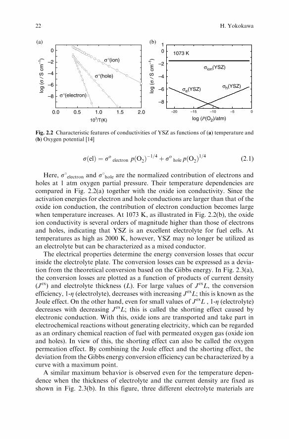
sðelÞ ¼ so electron pðO2Þ�1=4 þ so hole pðO2Þ
1=4 (2:1)
Here, s8electron and s8hole are the normalized contribution of electrons andholes at 1 atm oxygen partial pressure. Their temperature dependencies arecompared in Fig. 2.2(a) together with the oxide ion conductivity. Since theactivation energies for electron and hole conductions are larger than that of theoxide ion conduction, the contribution of electron conduction becomes largewhen temperature increases. At 1073 K, as illustrated in Fig. 2.2(b), the oxideion conductivity is several orders of magnitude higher than those of electronsand holes, indicating that YSZ is an excellent electrolyte for fuel cells. Attemperatures as high as 2000 K, however, YSZ may no longer be utilized asan electrolyte but can be characterized as a mixed conductor.
The electrical properties determine the energy conversion losses that occurinside the electrolyte plate. The conversion losses can be expressed as a devia-tion from the theoretical conversion based on the Gibbs energy. In Fig. 2.3(a),the conversion losses are plotted as a function of products of current density(Jex) and electrolyte thickness (L). For large values of JexL, the conversionefficiency, 1-Z (electrolyte), decreases with increasing JexL; this is known as theJoule effect. On the other hand, even for small values of JexL , 1-Z (electrolyte)decreases with decreasing JexL; this is called the shorting effect caused byelectronic conduction. With this, oxide ions are transported and take part inelectrochemical reactions without generating electricity, which can be regardedas an ordinary chemical reaction of fuel with permeated oxygen gas (oxide ionand holes). In view of this, the shorting effect can also be called the oxygenpermeation effect. By combining the Joule effect and the shorting effect, thedeviation from the Gibbs energy conversion efficiency can be characterized by acurve with a maximum point.
A similar maximum behavior is observed even for the temperature depen-dence when the thickness of electrolyte and the current density are fixed asshown in Fig. 2.3(b). In this figure, three different electrolyte materials are
(a)
0.0 0.5 1.0 1.5 2.0
–8
–6
–4
–2
log
(σ /
S c
m–1
)
log
(σ /
S c
m–1
)
0
103/T(K)
σ°(electron)
σ°(hole)
σ°(ion)
–20 –15 –10 –5 0
–8
–6
–4
–2
01
log (P(O2)/atm)
1073 K
(b)
σion(YSZ)
σe(YSZ)σh(YSZ)
Fig. 2.2 Characteristic features of conductivities of YSZ as functions of (a) temperature and(b) Oxygen potential [14]
22 H. Yokokawa
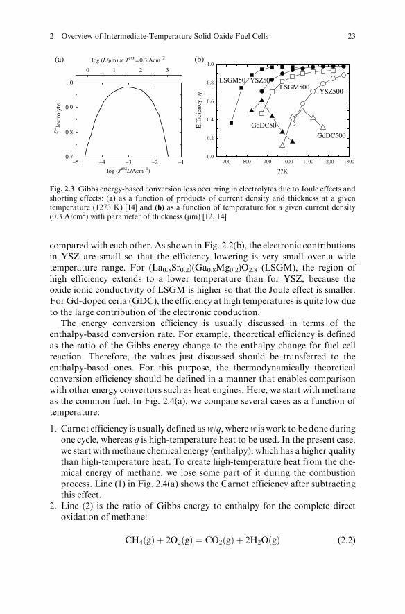
compared with each other. As shown in Fig. 2.2(b), the electronic contributionsin YSZ are small so that the efficiency lowering is very small over a widetemperature range. For (La0.8Sr0.2)(Ga0.8Mg0.2)O2.8 (LSGM), the region ofhigh efficiency extends to a lower temperature than for YSZ, because theoxide ionic conductivity of LSGM is higher so that the Joule effect is smaller.For Gd-doped ceria (GDC), the efficiency at high temperatures is quite low dueto the large contribution of the electronic conduction.
The energy conversion efficiency is usually discussed in terms of theenthalpy-based conversion rate. For example, theoretical efficiency is definedas the ratio of the Gibbs energy change to the enthalpy change for fuel cellreaction. Therefore, the values just discussed should be transferred to theenthalpy-based ones. For this purpose, the thermodynamically theoreticalconversion efficiency should be defined in a manner that enables comparisonwith other energy convertors such as heat engines. Here, we start with methaneas the common fuel. In Fig. 2.4(a), we compare several cases as a function oftemperature:
1. Carnot efficiency is usually defined asw/q, wherew is work to be done duringone cycle, whereas q is high-temperature heat to be used. In the present case,we start with methane chemical energy (enthalpy), which has a higher qualitythan high-temperature heat. To create high-temperature heat from the che-mical energy of methane, we lose some part of it during the combustionprocess. Line (1) in Fig. 2.4(a) shows the Carnot efficiency after subtractingthis effect.
2. Line (2) is the ratio of Gibbs energy to enthalpy for the complete directoxidation of methane:
CH4ðgÞ þ 2O2ðgÞ ¼ CO2ðgÞ þ 2H2OðgÞ (2:2)
0.7
0.8
0.9
1.0
log (L /μm) at Jext = 0.3 Acm–2ε E
lect
roly
te
log (J
extL/Acm–1)
0 1 2 3
–5 –4 –3 –2 –1
(a)
700 800 900 1000 1100 1200 13000.0
0.2
0.4
0.6
0.8
1.0
GdDC500
GdDC50
LSGM50LSGM500
YSZ50
YSZ500
Eff
icie
ncy,
η
T/K
(b)
Fig. 2.3 Gibbs energy-based conversion loss occurring in electrolytes due to Joule effects andshorting effects: (a) as a function of products of current density and thickness at a giventemperature (1273 K) [14] and (b) as a function of temperature for a given current density(0.3 A/cm2) with parameter of thickness (mm) [12, 14]
2 Overview of Intermediate-Temperature Solid Oxide Fuel Cells 23
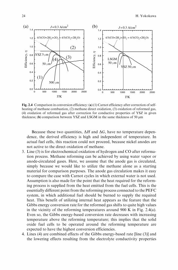
Because these two quantities, DH and DG, have no temperature depen-
dence, the derived efficiency is high and independent of temperature. In
actual fuel cells, this reaction could not proceed, because nickel anodes are
not active to the direct oxidation of methane.3. Line (3) is for electrochemical oxidation of hydrogen and CO after reforma-
tion process. Methane reforming can be achieved by using water vapor oranode-circulated gases. Here, we assume that the anode gas is circulated,simply because we would like to utilize the methane alone as a startingmaterial for comparison purposes. The anode gas circulation makes it easyto compare the case with Carnot cycles in which external water is not used.Assumption is also made for the point that the heat required for the reform-ing process is supplied from the heat emitted from the fuel cells. This is theessentially different point from the reforming process connected to the PEFCsystem, in which additional fuel should be burned to supply the requiredheat. This benefit of utilizing internal heat appears as the feature that theGibbs energy conversion rate for the reformed gas shifts to quite high valuesin the vicinity of the reforming temperatures around 900 K in Fig. 2.4(a).Even so, the Gibbs energy-based conversion rate decreases with increasingtemperature above the reforming temperature; this implies that the solidoxide fuel cells to be operated around the reforming temperature areexpected to have the highest conversion efficiencies.
4. Lines (4) are combined effects of the Gibbs energy-based rate [line (3)] andthe lowering effects resulting from the electrolyte conductivity properties
(1)
(2)
(3) (4)
0.0
0.2
0.4
0.6
0.8
1.0
1.2
1.4
4/3(CO+2H2)+2O2 = 4/3(CO2+2H2O)
J = 0.3 A/cm2
YSZ
500 μm
Eff
icie
ncy,
η
T/K
0 500 1000 1500 2000 2500
(a)
4/3(CO+2H2)+2O2 = 4/3(CO2+2H2O)
J = 0.3 A/cm2
0 500 1000 1500 2000 25000.0
0.2
0.4
0.6
0.8
1.0
1.2
1.4
LSGM
YSZEff
icie
ncy,
ηT/K
(b)
50 μm
5 μm
50 μm50 μm
Fig. 2.4 Comparison in conversion efficiency: (a) (1) Carnot efficiency after correction of self-heating of methane combustion, (2) methane direct oxidation, (3) oxidation of reformed gas,(4) oxidation of reformed gas after correction for conductive properties of YSZ in giventhickness; (b) comparison between YSZ and LSGM in the same thickness of 50 mm
24 H. Yokokawa
from the Gibbs energy-based rate. For YSZ electrolyte, three values corre-sponding to different thickness values are taken from those in Fig. 2.3(b).Figure 2.4(a) shows, in a clearer manner, the effect of electrolyte thickness.For YSZ, the thickness of 50 mm adopted first byWHPC in the EVD processprovides rather good efficiency even at a temperature lower than 1273 K.The thinner YSZ can provide more efficient SOFC systems. In view of this,the anode-supported cells are of strong interest and importance for devel-oping the intermediate-temperature SOFCs.
In Fig. 2.4(b), comparison is made between YSZ and LSGM for identicalthickness values of 50 mm, which indicates the superiority of higher oxide ionconductors in the intermediate-temperature SOFCs. Particularly, technologicalconditions are quite different. For YSZ, anode-supported cells are inevitablyrequired, whereas the self-supported cells can be operated around 1073 K forLSGM. Actually, Mitsubishi Materials Corporation successfully designed andmanufactured SOFC systems based on the self-supporting LSGMC cells, con-firming that the obtained efficiency is high, as is described in the followingsections.
2.2.2.2 Cathode
Relationship with YSZ and Cr Poisoning
In the first generation of SOFC to be operated around 1273 K, the lanthanumstrontium manganites [(La1-xSrx)MnO3, LSM] have been well investigatedbecause of their higher cathode activity and compatibility with the YSZ elec-trolyte [15]. Since the chemical stability was much more important in the firstgeneration, LSM has been utilized widely in actual stacks. When LSM is usedfor intermediate-temperature SOFCs, it has been found that the performance ofLSM on the anode support cells is degraded rapidly with decreasing tempera-ture. In addition, LSM is poor against the Cr poisoning [16], which is caused bythe chromium-containing vapors emitted from Cr2O3 oxide scale on the metalinterconnects.
Lanthanum strontium cobaltite [(La1–xSrx)CoO3, LSC] was the first perovs-kite-type oxide investigated as a SOFC cathode in 1969 [17]. Even in thisattempt, it was found that LSC degraded rapidly because of a chemical reactionwith YSZ. Since then, major investigations on cathodes moved to the lantha-num strontium manganites. The recent trend of lowering operation tempera-ture, however, leads again to the investigation of LSC, (La1–xSrx)FeO3 (LSF),and (La1–xSrx)(Co1–yFey)O3 (LSCF) by using the interlayer made up of dopedceria between YSZ and those perovskite cathodes.
It is interesting to see the work by Matsuzaki and Yasuda [18], who inves-tigated Cr poisoning using different combinations of electrolyte and cathodes;as electrolyte, they selected YSZ and samarium-doped ceria (SDC), and LSMand LSCF were selected as cathodes. As shown in Fig. 2.5, a potential dropfrom Cr poisoning is largest and most rapid for LSM/YSZ, whereas LSCF/
2 Overview of Intermediate-Temperature Solid Oxide Fuel Cells 25
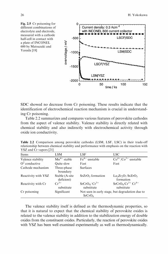
SDC showed no decrease from Cr poisoning. These results indicate that the
identification of electrochemical reaction mechanism is crucial in understand-
ing Cr poisoning.Table 2.2 summarizes and compares various features of perovskite cathodes
from the aspect of valence stability. Valence stability is directly related with
chemical stability and also indirectly with electrochemical activity through
oxide ion conductivity.
The valence stability itself is defined as the thermodynamic properties, sothat it is natural to expect that the chemical stability of perovskite oxides isrelated to the valence stability in addition to the stabilization energy of doubleoxides from the constituent oxides. Particularly, the reaction of perovskite oxideswith YSZ has been well examined experimentally as well as thermodynamically.
Fig. 2.5 Cr poisoning fordifferent combinations ofelectrolyte and electrode,measured with a cathodehalf-cell in contact witha plate of INCONEL600 by Matsuzaki andYasuda [18]
Table 2.2 Comparison among perovskite cathodes (LSM, LSF, LSC) in their trade-offrelationship between chemical stability and performance with emphasis on the reaction withYSZ and Cr vapors [21]
Items LSM LSF LSC
Valence stability Mn4þ stable Fe4þ unstable Co4þ/Co3þ unstable
O2 conductive Quite slow Fast Fast
Cathode mechanism Three-phaseboundary
Surfaces
Reactivity with YSZ Stable (A-sitedeficient)
SrZrO3 formation La2Zr2O7 SrZrO3
formation
Reactivity with Cr Cr3þ
substituteSrCrO4/ Cr
3þ
substituteSrCrO4/Cr
3þ Cr4þ
substitute
Cr poisoning Significant Not seen in early stage, but degradation due toSrCrO4
26 H. Yokokawa
The formation of La2Zr2O7/SrZrO3 at the interfaces is accompanied with the
reduction of transition metal oxides and precipitation of compounds with
reduced valence ions [19]. Recently, chemical reactions of perovskite oxides with
chromium-containing vapors have been analyzed in a similar manner, and it
has been found that reactivity with chromium vapor is of the same order among
the LSM, LSF, and LSC as reactions with YSZ [20, 21]. That is, the Sr component
in the perovskite oxides can react with Cr vapors to form SrCrO4 for LSF and
LSC but not for LSM, which exhibits the most severe Cr poisoning effect. This
result implies that chemical reactivity alone cannot explain the Cr poisoning effect,
because LSM exhibits most severe Cr poisoning effect, although LSM is most
stable against reactions with Cr vapors.The oxide ion vacancies in the perovskite ABO3 oxides are formed as a result
of reduction of the B-site ions on substitution of Sr2þ ions to the La3þ (A) sites;
this will lead to mixed conductivity of lanthanum strontium transition metal
oxides. Even so, the oxide ion vacancy formation is competing with the oxida-
tion of transition metal ions in the B sites. The latter depends on the valence
stability of the transition metal ions. For the case of (La,Sr)MnO3, the tetra
valence of manganese ions is stable in the perovskite lattice so that the Sr
substitution gives rise to the oxidation of manganese ions from 3+ to 4+
and to essentially no oxide ion vacancy formation. As a result, the oxide ion
conductivity in LSM is not high. This fact affects the reaction mechanism; that
is, only the three-phase boundaries (TPB) are electrochemical active sites for the
LSM cathode, whereas the high oxide ion conductivity in LSF and LSC
provides wider distribution of electrochemically active sites. This difference
on the distribution of active sites in relationship to the oxide ion conductivity
leads to different features in the oxygen flow and associated with the oxygen
potential distribution.This difference in the oxygen flow and distributions of active sites and of
oxygen potential provides a good basis of explaining the difference in the Cr
poisoning. For LSM, the oxygen flow has to be concentrated in the TPB where
Cr tends to be deposited, whereas the chemical reaction with Cr vapors can take
place at any point of the LSF or LSC surfaces, but the oxygen flow can be
changed to avoid such reaction sites. For long-term stability, however, SrCrO4
formation should be avoided to maintain mechanical stability as well as che-
mical stability.It is generally considered that the cathodes for intermediate-temperature
SOFCs should be electrochemically more active than those cathodes in the
first generation, namely, LSM. When LSF, LSC, or LSCF is used as cathode,
an interlayer made of doped ceria becomes inevitable to avoid chemical reac-
tions between cathode and YSZ. In addition, such cathodes should be also
protected against Cr vapors. This approach gives rise to a complicated layer
structure across the electrolyte to current collector and makes it difficult to
fabricate such complicated layers. For example, the following points are
important:
2 Overview of Intermediate-Temperature Solid Oxide Fuel Cells 27
1. Doped ceria–YSZ interface. Solid solutions between doped ceria and YSZprovide interesting systems for investigating the transport and related prop-erties [22, 23]. That is, the ionic conductivity has a minimum in the middleof the Ce concentration range, whereas the electronic conductivity hasa maximum. Similarly, the surface exchange reaction rate exhibit strongconcentration dependence. This property suggests that when the dopedceria–YSZ interface was prepared in a well-bonded state at interfaces bysintering at high temperatures, interdiffusion takes place across the interface,forming a layer with high electrical resistance. Furthermore, interdiffusionsometimes gives rise to Kirkendall pores in the ceria side because of thedifferences in diffusivities of zirconia and ceria [24].
2. Strictly speaking, interfaces between perovskite cathode and doped ceria arenot thermodynamically stable, and some chemical reactions can take place[21, 25]. In addition, cation diffusion can occur. In particular, Sr diffusionthrough doped ceria is important. There are some differences between LSFand LSC as far as reactivity and interdiffusion are concerned; that is, noproducts are formed for the diffusion couple between Gd-doped ceria(GDC) and LSC, because GdCoO3 exhibits no thermodynamic stability.In other interfaces, there arises a driving force of forming another perovskitephase from the dopant in ceria and the B-site ions (Fe or Co ions) in theperovskite; this is accompanied with Sr diffusion.
3. To obtain a stable interface between cathode and metal interconnect, it isessential to adopt a coating layer on the interconnect to prevent the migra-tion of Cr from the metal alloys.
Compatibility with LSGM
Immediately after the discovery of LSGM by Ishihara [7,8], it became clear thatinterdiffusion associated with LSGM is significant between LSGMand cathodeelectrode [26]; this makes it difficult to prepare cathode-supported cells in whichthe cathode–electrolyte interfaces are exposed to high temperatures. Currently,(Sm,Sr)CoO3 is widely utilized as a cathode material on the basis of Ishihara’sresults [27].
Because (Sm,Sr)CoO3 exhibits similar features to those of (La,Sr)CoO3,reactions with Cr vapors are also technologically important issues. That is,immediate degradation of SSC cathodes is not expected, but the formation ofSrCrO4 leads to changes in microstructure and other properties. Particularly,the thermal expansion coefficients of the Sr-depleted cobaltites and of theformed SrCrO4 are both large.
2.2.2.3 Anode
Even for the intermediate-temperature SOFCs, Ni is the best anode as far as thecurrent technological status is concerned. Although a number of investigationshave been made on oxide anodes, nickel cermet (ceramic-metal) anodes exhibit
28 H. Yokokawa
excellent ability of dissociating hydrogen bonds. As the oxide component of
cermet anodes, YSZ is frequently used. In recent years, ScSZ or doped ceria
have attracted attention because characteristic features against carbon deposition
or sulfur poisoning can be improved by the use of these oxides instead of YSZ.
Nickel Anode
Technological issues associated with nickel anodes can be summarized as
follows.
1. Sintering: In the first-generation SOFCs, sintering of nickel anodes and theassociated degradation are one of the major issues because the high operationtemperature promotes sintering during long operation times. Furthermore,nickel microstructure can be heavily damaged to form metastable Ni-Cliquids in the presence of carbon. In the intermediate-temperature SOFCs,however, these mechanisms of sintering or change in microstructure causedby the Ni-C liquids are expected to diminish.
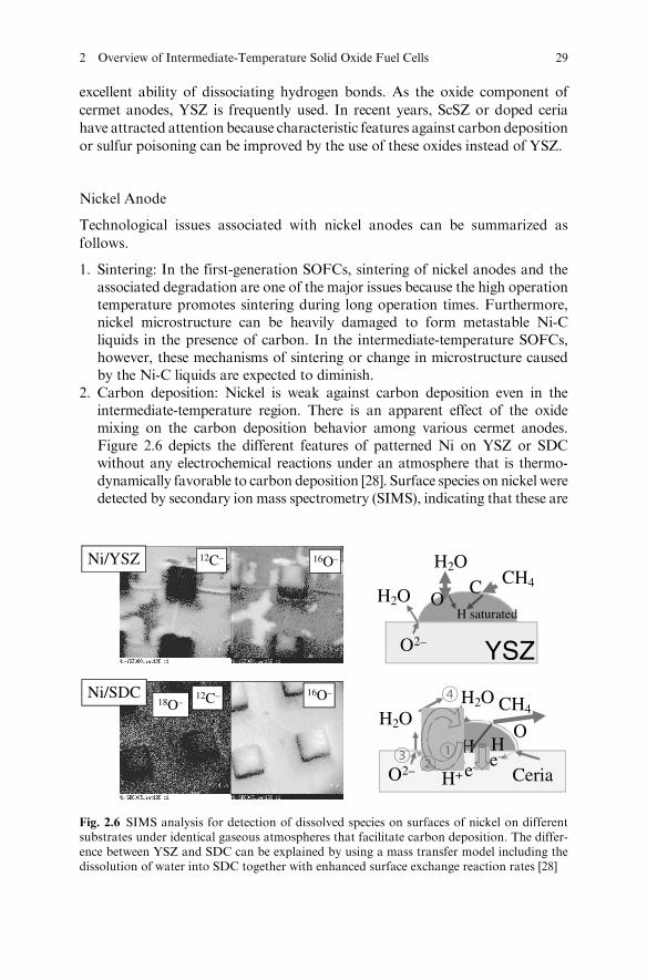
2. Carbon deposition: Nickel is weak against carbon deposition even in theintermediate-temperature region. There is an apparent effect of the oxidemixing on the carbon deposition behavior among various cermet anodes.Figure 2.6 depicts the different features of patterned Ni on YSZ or SDCwithout any electrochemical reactions under an atmosphere that is thermo-dynamically favorable to carbon deposition [28]. Surface species on nickel weredetected by secondary ion mass spectrometry (SIMS), indicating that these are
16O–12C–
18O–16O–12C–
Ni/YSZ
Ni/SDC
H2O
H2O
H2OH2O
OCH4
CH4
C
YSZO2–
H saturated
O
H+ Ceria
He–
He–
O2–
Fig. 2.6 SIMS analysis for detection of dissolved species on surfaces of nickel on differentsubstrates under identical gaseous atmospheres that facilitate carbon deposition. The differ-ence between YSZ and SDC can be explained by using a mass transfer model including thedissolution of water into SDC together with enhanced surface exchange reaction rates [28]
2 Overview of Intermediate-Temperature Solid Oxide Fuel Cells 29
not adsorbed species but dissolved atoms. For Ni/YSZ, carbon covers almostthe entire surface of nickel and only a small amount of oxygen is present on thesurface. Under the same condition, Ni/SDC exhibits quite different features ofnickel surface. That is, the nickel surface is covered by oxygen instead ofcarbon. This observation can be reasonably explained by considering themass transfer mechanism in which nonnegligible water solubility in ceria, andenhanced surface reaction at the ceria surface, can be accounted for as differentfeatures. Under a polarization of the Ni/YSZ combination, a similar coverageof oxygen was observed on nickel, indicating that the above mechanism isclosely related with the anode reaction mechanism.
3. Sulfur poisoning: From the earlier stages of the development of SOFCs, ithas been well known that, in the presence of a small amount of hydrogensulfide, the anode activity is lowered but will recover after switching back tonon-hydrogen sulfide fuels [29]. In addition to this reversible lowering activ-ity, nickel anodes show irreversible degradation at higher concentration ofH2S or at lower temperatures.
4. Redox cycle tolerance [30]: As anode-supported cells have been investigatedextensively, redox cycles are recognized as quite important. One reason is thatthe anode-supported cells inevitably have a sealing problem on their edges.Because the anode is used as the supporting body, its mechanical stabilitybecomes crucial. Another reason originates from the purge gas. When nitrogenis used as a purge gas, nickel anodes are always protected against reoxidation.However, for cases where nitrogen cannot be used due to system requirements,etc., stability during redox cycles becomes also a crucial technological matter.This phenomenon is closely related with diffusion of Ni and reconstruction ofmicrostructure on reduction from NiO to Ni; this is because diffusion of Ni inthemetal phase is faster thanNi2þ ions in the oxide. On the reduction of NiO ina mixture of NiO and YSZ (or other oxides), fine powers of nickel are formed,and then the electrical path will be established using powders by diffusion in theframework of YSZ. On reoxidation of nickel, NiO does not move so thatvolume expansion on oxidation takes place in the framework of YSZ. Becausenickel wasmoved from the original position, the reoxidation gives rise to partialdestruction of the framework as a result of a single redox cycle.
These features are closely related with the selection of the oxide component
in cermet anodes. When Sc2O3-stabilized zirconia (ScSZ) is used instead of
YSZ, some improvements have been obtained for carbon deposition [31] or
resistance for sulfur poisoning [32]. These degradations should be discussed
on the basis of the anode reaction mechanism. Even so, a large number of
investigations have been made on reaction mechanisms, but unfortunately no
reasonable agreement has been obtained among researchers. Here, a brief
discussion is made about the role of the oxide component.The surface reaction rate and the water solubility in ScSZ are found to be
about the same as those of YSZ [33]; this implies that merits of using ScSZ may
originate from properties such as the oxide ion conductivity or the cation
30 H. Yokokawa
diffusivity affecting the microstructure of cermet anodes. In particular, higheroxide ion conductivity values positively affect the anode activities againstcarbon deposition or sulfur poisoning. As to carbon deposition, the watervapor emitted from active sites may have strong effects of avoiding carbondeposition by transferring oxygen atoms from the electrolyte to the nickelsurface. When the current density is the same, the same amount of watervapor should be emitted. So, effects of higher oxide ion conductivity appearonly in the distribution of electrochemically active sites. When the oxide ionconductivity is low, only the TPB located at the bottom of the anode layerbecomes active, whereas the TPB even far from the bottom can be active whenthe oxide ion conductivity is high in the oxide component of cermet anodes. Forthe case of sulfur poisoning, the equilibrium shift should be considered as afunction of anode overpotential as well as fuel utilization. Here, the overpoten-tial should be related to the oxide ion conductivity.
Nickel Anode with LSGM Electrolyte
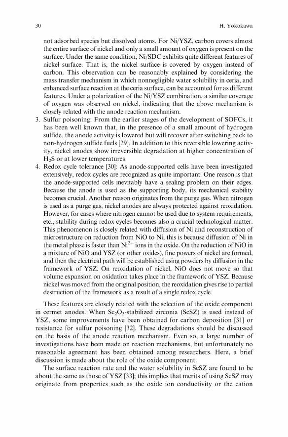
For the LSGM electrolyte, the doped ceria is used as the oxide component incermet anodes. The interface between doped ceria and LSGM is rather stable,although some interdiffusion occurs. One of the biggest issues associated withthe nickel anode used together with LSGM electrolyte is that the dissolution ofNiO into perovskite phase takes place significantly during the high-temperaturesintering process of cells; this occurs because in air the LaNiO3 perovskite phaseis rather stable so that NiO can be easily dissolved into the LSGM/LSGMCphases. In a worst case, NiO can penetrate completely to the cathode side. Thisphenomenon should be avoided, because NiO in LSGM can be reduced againto Ni metal by hydrogen so that the reduced Ni can cause electronic shortingpaths inside the LSGM electrolyte. Figure 2.7 shows the distribution of
Anode
ElectrolyteCurrentCollector
88Sr
58Ni
24Mg
LSGMC
Fig. 2.7 The elemental distribution detected with SIMS technique after 24-h operation ofsealless disk-type cells made by Mitsubishi Materials Corp. [34]
2 Overview of Intermediate-Temperature Solid Oxide Fuel Cells 31
elements in an actual LSGMC-based cell operated for 24 h obtained by sec-ondary ion mass spectroscopy (SIMS) technique. The cell was fabricated andtested by Mitsubishi Materials Corporation [34]. It is clearly seen that the Nidissolution into the LSGMC layer was successfully prevented during the fabri-cation process.
Oxide Anodes
Recently efforts have been made on oxide anodes. The main reason for suchinvestigations is to overcome the demerits of Ni cermet anodes as just described.Although the oxide anodes should be in service under a reducing atmosphere,the fabrication is usually performed in air so that oxide anodes should be stableat both oxidative and reductive atmospheres. This requirement is similar tothose for oxide interconnects, implicitly indicating that material selectionbecomes severe to meet the chemical stability requirement.
Doped ceria and doped lanthanum chromites were investigated a long timeago because ceria is a mixed conductor in a reducing atmosphere, whereaslanthanum chromites are typical candidates for oxide interconnects. Neitherof the materials shows good performance as an anode. In recent years, othertypes of perovskite oxides have attracted attention, as is described in otherchapters of this book. The basic trade-off relationship associated with oxideanodes is stability versus performance.
2.2.2.4 Metal Interconnects
The reasons to utilize metal interconnects [13] instead of oxide interconnects[35, 36] may be listed as follows:
1. Material cost: La in the oxide interconnect is expensive, whereas ferriticalloys can be regarded as inexpensive.
2. Difficulty in fabricating LaCrO3-based interconnects: Particularly, sinteringin air is the most challenging. Although no SOFC stacks can be fabricatedwithout establishing an appropriate technology for fabricating dense oxideinterconnects, only a few manufacturers have succeeded in sintering oxideinterconnects properly and constructing them into SOFC stacks. On theother hand, fabrication of metals is usually much easier than that of theLaCrO3-based oxides. For oxide dispersed alloys such as Cr5Fe1Y2O3, how-ever, special technology is required to fabricate these into a shape for SOFCstacks.
3. High thermal conductivity: Management of temperature distribution insidestacks is essential in solid oxide fuel cells to protect the fragile ceramiccomponents.
4. High mechanical stability: To moderate the thermal stresses in ceramicsystems, it is essential to shorten the relaxation times for thermal fluctuationsby using materials with low thermal expansion coefficients and high thermal
32 H. Yokokawa
conductivities. Because YSZ electrolyte cannot meet such requirements byitself, it becomes essential to use metal components in SOFC stacks.
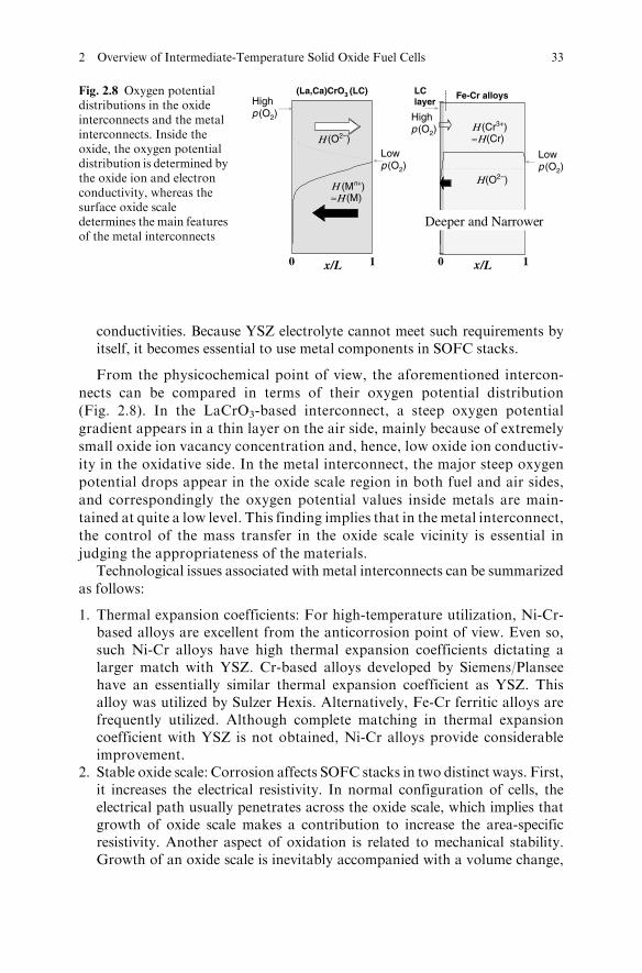
From the physicochemical point of view, the aforementioned intercon-
nects can be compared in terms of their oxygen potential distribution
(Fig. 2.8). In the LaCrO3-based interconnect, a steep oxygen potential
gradient appears in a thin layer on the air side, mainly because of extremely
small oxide ion vacancy concentration and, hence, low oxide ion conductiv-
ity in the oxidative side. In the metal interconnect, the major steep oxygen
potential drops appear in the oxide scale region in both fuel and air sides,
and correspondingly the oxygen potential values inside metals are main-
tained at quite a low level. This finding implies that in the metal interconnect,
the control of the mass transfer in the oxide scale vicinity is essential in
judging the appropriateness of the materials.Technological issues associated with metal interconnects can be summarized
as follows:
1. Thermal expansion coefficients: For high-temperature utilization, Ni-Cr-based alloys are excellent from the anticorrosion point of view. Even so,such Ni-Cr alloys have high thermal expansion coefficients dictating alarger match with YSZ. Cr-based alloys developed by Siemens/Planseehave an essentially similar thermal expansion coefficient as YSZ. Thisalloy was utilized by Sulzer Hexis. Alternatively, Fe-Cr ferritic alloys arefrequently utilized. Although complete matching in thermal expansioncoefficient with YSZ is not obtained, Ni-Cr alloys provide considerableimprovement.
2. Stable oxide scale: Corrosion affects SOFC stacks in two distinct ways. First,it increases the electrical resistivity. In normal configuration of cells, theelectrical path usually penetrates across the oxide scale, which implies thatgrowth of oxide scale makes a contribution to increase the area-specificresistivity. Another aspect of oxidation is related to mechanical stability.Growth of an oxide scale is inevitably accompanied with a volume change,
(La,Ca)CrO3 (LC) LClayer
x/Lx/L 10 0 1
Η≈Η (M)
Η (Cr3+)≈Η (Cr)
Η (O2–)
Η (O2–)
Highp (O2) High
p (O2)
Lowp (O2)
Lowp (O2)
Fe-Cr alloys
Deeper and Narrower
(Mn+)
Fig. 2.8 Oxygen potentialdistributions in the oxideinterconnects and the metalinterconnects. Inside theoxide, the oxygen potentialdistribution is determined bythe oxide ion and electronconductivity, whereas thesurface oxide scaledetermines the main featuresof the metal interconnects
2 Overview of Intermediate-Temperature Solid Oxide Fuel Cells 33
causing mechanical instability. From these, the oxide scale of a metal inter-connect should be thin and electrically conductive.
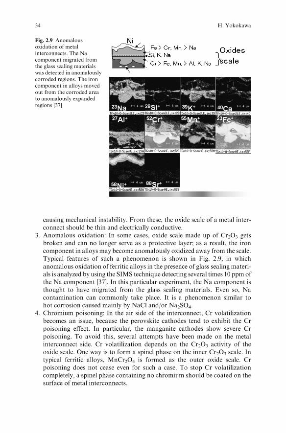
3. Anomalous oxidation: In some cases, oxide scale made up of Cr2O3 getsbroken and can no longer serve as a protective layer; as a result, the ironcomponent in alloys may become anomalously oxidized away from the scale.Typical features of such a phenomenon is shown in Fig. 2.9, in whichanomalous oxidation of ferritic alloys in the presence of glass sealing materi-als is analyzed by using the SIMS technique detecting several times 10 ppm ofthe Na component [37]. In this particular experiment, the Na component isthought to have migrated from the glass sealing materials. Even so, Nacontamination can commonly take place. It is a phenomenon similar tohot corrosion caused mainly by NaCl and/or Na2SO4.
4. Chromium poisoning: In the air side of the interconnect, Cr volatilizationbecomes an issue, because the perovskite cathodes tend to exhibit the Crpoisoning effect. In particular, the manganite cathodes show severe Crpoisoning. To avoid this, several attempts have been made on the metalinterconnect side. Cr volatilization depends on the Cr2O3 activity of theoxide scale. One way is to form a spinel phase on the inner Cr2O3 scale. Intypical ferritic alloys, MnCr2O4 is formed as the outer oxide scale. Crpoisoning does not cease even for such a case. To stop Cr volatilizationcompletely, a spinel phase containing no chromium should be coated on thesurface of metal interconnects.
Fig. 2.9 Anomalousoxidation of metalinterconnects. The Nacomponent migrated fromthe glass sealing materialswas detected in anomalouslycorroded regions. The ironcomponent in alloys movedout from the corroded areato anomalously expandedregions [37]
34 H. Yokokawa
2.2.3 Stack Design
The stack design and its fabrication process are quite important in developing
the SOFC systems. For the case of the first-generation SOFCs, selection of
materials was accompanied by adoption of the electrochemical vapor deposition
technique and the sealless tubular design. For the intermediate-temperature
SOFCs, utilization of metals is a key in selecting the fabrication technique and
the design. Typical designs are as follows:
1. Sealless planar: Electrochemical cells made up of electrolyte, cathode, andanode are stacked with metal interconnects without using sealing materials.For example, disk-type planar sealless stacks have been constructed byMitsubishi Materials Corporation. For this purpose, fuel and air are intro-duced through the central part of the respective cells. Outside the cells, theremaining fuel becomes combusted with air. Self-supporting cells are usuallyused for this design.
2. Planar cells with sealant: Fuel and air are separately controlled using sealingmaterials. Anode-supported cells are used for this design, which makes itnecessary to seal properly the edge part of anode-supported cells.
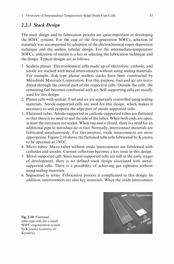
3. Flattened tubes: Anode-supported or cathode-supported tubes are flattenedso that there is no need to seal the side of the tubes.When both ends are open,at least the entrances are sealed.When one end is closed, there is a need for anadditional pipe to introduce air or fuel. Normally, interconnect materials arefabricated simultaneously. For this purpose, oxide interconnects are moreappropriate. Figure 2.10 shows the flattened tube cells fabricated byKyocerato be operated at 7508C.
4. Micro tubes: Micro tubes without oxide interconnects are fabricated withcathodes and anodes. Current collection becomes a key issue in this design.
5. Metal-supported cell: Since metal-supported cells are still in the early stagesof development, there is no defined stack design associated with metal-supported cells. There is a possibility of achieving gas tightness withoutusing sealing materials.
6. Segmented in series: Fabrication process is complicated in this design. Inaddition, interconnects are also key materials. When the oxide interconnect
Cell Appearance
Fig. 2.10 Flattenedtube-type cells for a smallSOFC cogeneration systemby Kyocera (courtesy ofKyocera)
2 Overview of Intermediate-Temperature Solid Oxide Fuel Cells 35
is adopted, the same ceramic processing can be applied. In other words,proper manufacturing techniques addressing the problems in air sinteringare essential. When metal interconnects are used, it becomes crucial to findappropriate methods for simultaneous fabrication of metals and ceramics.
2.3 Development of Intermediate Temperature SOFC Stacks/Systems
2.3.1 Kyocera/Osaka Gas
After fundamental investigations on SOFC materials for a long period of time,Kyocera started the development of a small SOFC cogeneration system forresidential houses in 2001. Although similar developments have been made bySulzer Hexis for the last decade in cooperation with utility companies/localgovernments in Germany, there are some important differences between thetwo SOFC systems; that is, the Sulzer system is based on supplying 1 kWelectricity and 2 kW heat for domestic utilization, whereas the Kyocera systemhas focused on those small systems with high conversion efficiency of generat-ing electricity. This difference is mainly the result of strong requirements forelectricity rather than heat in the Japanese market. To achieve this requirementtechnologically, lowering the operation temperature is effective to reduce theheat losses of the SOFC stacks and therefore to maintain high efficiency even insmaller systems.
Kyocera adopted the flattened tube design shown in Fig. 2.10. The YSZelectrolyte is fabricated on a cermet anode substrate having gas channels forfuel flow. One side of the anode flattened tube is coated with the LaCrO3-basedinterconnect. In Fig. 2.10, both sides of the SOFC are shown. These flattenedtubes are unique in the sense that they use metals as cell-to-cell connection. Thisdesign should be compared with sealless tubular cells by Westinghouse PowerCorp., in which the cell-to-cell connection is made with nickel felt. Nickel isthermodynamically stable in a fuel atmosphere so that the adoption of nickelmakes it possible to establish stable and effective connection among tubes. Inother words, WHPC adopted the cathode-supported tube and made the fuelside as the outer side of the tubes to realize a thermodynamically stable cell-to-cell connection. On the other hand, Kyocera adopted the reverse; flattenedtubes were made as anode supported, and, as a result, the cell-to-cell connectionshould be made on the air side. For this design, therefore, utilization of (non-precious) metal connection becomes the technological key point. In this sense,the lowering of operation temperature is essential.
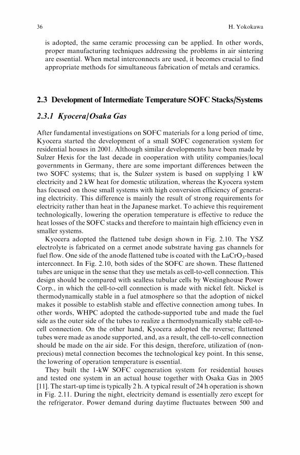
They built the 1-kW SOFC cogeneration system for residential housesand tested one system in an actual house together with Osaka Gas in 2005[11]. The start-up time is typically 2 h. A typical result of 24 h operation is shownin Fig. 2.11. During the night, electricity demand is essentially zero except forthe refrigerator. Power demand during daytime fluctuates between 500 and
36 H. Yokokawa
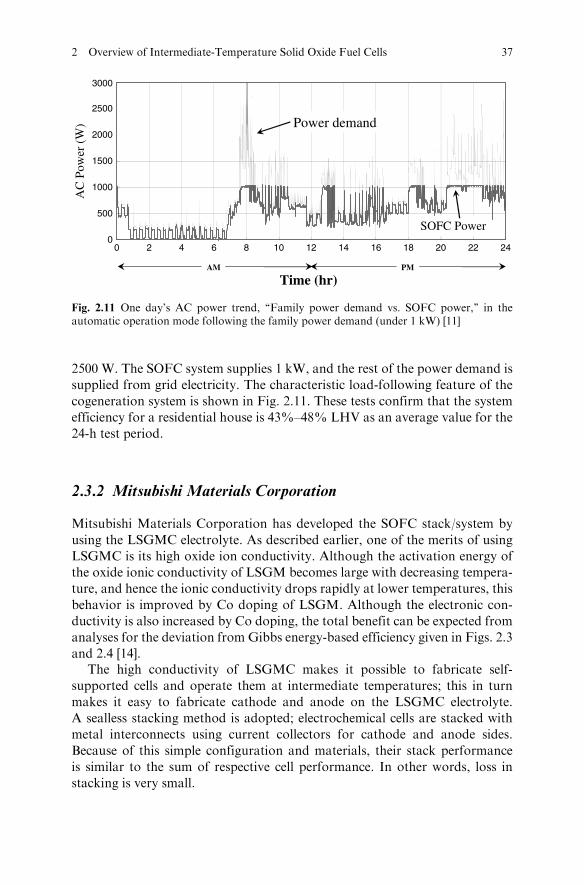
2500 W. The SOFC system supplies 1 kW, and the rest of the power demand is
supplied from grid electricity. The characteristic load-following feature of the
cogeneration system is shown in Fig. 2.11. These tests confirm that the system
efficiency for a residential house is 43%–48% LHV as an average value for the
24-h test period.
2.3.2 Mitsubishi Materials Corporation
Mitsubishi Materials Corporation has developed the SOFC stack/system by
using the LSGMC electrolyte. As described earlier, one of the merits of using
LSGMC is its high oxide ion conductivity. Although the activation energy of
the oxide ionic conductivity of LSGM becomes large with decreasing tempera-
ture, and hence the ionic conductivity drops rapidly at lower temperatures, this
behavior is improved by Co doping of LSGM. Although the electronic con-
ductivity is also increased by Co doping, the total benefit can be expected from
analyses for the deviation from Gibbs energy-based efficiency given in Figs. 2.3
and 2.4 [14].The high conductivity of LSGMC makes it possible to fabricate self-
supported cells and operate them at intermediate temperatures; this in turn
makes it easy to fabricate cathode and anode on the LSGMC electrolyte.
A sealless stacking method is adopted; electrochemical cells are stacked with
metal interconnects using current collectors for cathode and anode sides.
Because of this simple configuration and materials, their stack performance
is similar to the sum of respective cell performance. In other words, loss in
stacking is very small.
0
500
1000
1500
2000
2500
3000
0 2 4 6 8 10 12 14 16 18 20 22 24
Power demand
SOFC Power
AM PM
AC
Pow
er (
W)
Time (hr)
Fig. 2.11 One day’s AC power trend, ‘‘Family power demand vs. SOFC power,’’ in theautomatic operation mode following the family power demand (under 1 kW) [11]
2 Overview of Intermediate-Temperature Solid Oxide Fuel Cells 37
As described in a separate chapter, the performance of their 1-, 3-, and 10-kW systems operated around 8008C is quite remarkable, and the systemsexhibit high conversion efficiencies. Typical stack efficiency is more than 50%HHV [38]. This result is consistent with the arguments made in Section 2.1 thata strong impact can be expected from the increase in ionic conductivity.
2.3.3 Micro SOFCs by TOTO
TOTO attempted to fabricate micro tubes in various types. Eventually, theyadopted the anode-supported tubular cells with the LSGM electrolyte. Theadoption of anode-supported cells much thinner LSGM electrolyte can beused, leading to higher benefits in performance. On the other hand, technolo-gical difficulty in the fabrication process becomes more visible to avoid inter-diffusion between cell components. Details are also described in a separatechapter of this book.
2.4 Perspective
2.4.1 Applications
The development of SOFC systems is governed first by materials selection.However, breakthrough by WHPC on the sealless tubular cells indicated thatnot only materials selection, but also materials processing techniques togetherwith stack design, are inevitably not separable and should be consideredtogether from the early stages of development. In this sense, the main applica-tion of WHCP stacks was a stationary power generator for a few hundredkilowatts.
Recent achievement by Kyocera reminds us another aspect of applications:‘‘For what purpose are the SOFC systems applied?’’ This question is the mostimportant point of the SOFC development. They started with the concept ofapplications to the residential houses and then selected the operation tempera-ture, plausible cost, and lifetime. On the basis of such system requirements, theystarted to construct their stacks.
One of their most important achievements is that they demonstrated that asmall system can be fabricated and operated as an efficient energy conversiondevice. There was an argument about the self-thermal sustainability of smallSOFC stacks, and it was thought that 1 kW is not sufficient to achieve self-thermal sustainability as well as high conversion efficiency simultaneously.Kyocera has demonstrated that this argument should be made by consideringtemperature as a parameter, and lowering the operating temperature makes itpossible to construct a small but efficient SOFC system. Another impact of theKyocera system is that they apply the SOFC system to residential houses by
38 H. Yokokawa
adopting appropriate load-following mode. In gas turbine systems connected
to grid electricity, the daily start-and-stop (DSS) operation mode is common,
so that whether this DSS operation mode can be applied was thought to be a
basic criterion for adaptability of SOFC systems to the electricity market,
particularly in Japan. The Kyocera system demonstrates that the DSS opera-
tion mode is not necessarily required. Instead, an effective load-following
feature can be sufficient for providing power in low-demand periods. In
view of this feature, the Kyocera system expands the applicability of SOFC
systems not only for nearly steady-state but also for highly transient
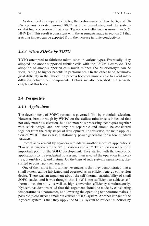
applications.In Figs. 2.12 and 2.13, some characteristic features of SOFC stacks and
SOFC systems are compared. In Fig. 2.12, the volumetric power density is
plotted as a function of stack power. In this evaluation, the gas manifold parts
are excluded. It is apparent that high volumetric power density can be
achieved in a rather small stack. For tubular stacks aiming at larger systems,
0.01 0.1 1 10 100 1000
0.1
1
Tube I
μ tubes
Plane III
D tube
F tubes
F tubes
Plane I
Plane II1.2 kW/L
Limit suggested by Makishima
Plane IV
Tube IIVol
ume
Pow
er D
ensi
ty,
kW/L
Unit Power, kW
Fig. 2.12 Comparison ofvolumetric power density ofcore stack portion amongrecently developed SOFCstacks as a function of stackpower. A limit of 1.2 kW/l issuggested by Makishima forlarge continuous chemicalreactors such as iron blastfurnaces
100 1 k 10 k 100 k 1 M 10 M
20
30
40
50
60
courtesy of Osaka gas
Gas engine
MCFCPAFC
PEFC
SOFC
(Kyoera)
LH
V E
ffic
ienc
y / %
Size / kW
SOFC
(WHPC)
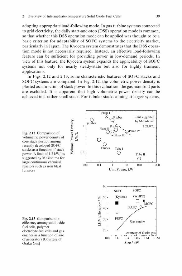
Fig. 2.13 Comparison inefficiency among solid oxidefuel cells, polymerelectrolyte fuel cells and gasengines as a function of sizeof generators [Courtesy ofOsaka Gas]
2 Overview of Intermediate-Temperature Solid Oxide Fuel Cells 39
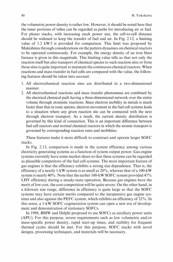
the volumetric power density is rather low. However, it should be noted here thatthe inner portions of tubes can be regarded as paths for introducing air or fuel.For planar stacks, with increasing stack power size, the cell-to-cell distanceshould be widened to keep the transfer of fuel and air. In Fig. 2.12, a limitingvalue of 1.2 kW/l is provided for comparison. This limit was proposed byMakishima through considerations on the pattern dynamics on chemical reactorsto be operated continuously. For example, the energy density of an iron blastfurnace is given in this magnitude. This limiting value tells us that not only thereaction itself but also transport of chemical species to such reaction sites or fromthose sites is quite important tomaintain the continuous chemical reactors.Whenreactions and mass transfer in fuel cells are compared with the value, the follow-ing features should be taken into account:
1. All electrochemical reaction sites are distributed in a two-dimensionalmanner.
2. All electrochemical reactions and mass transfer phenomena are combined bythe electrical chemical path having a three-dimensional network over the entirevolume through atomistic reactions. Since electron mobility in metals is muchfaster than that in ionic species, electronmovement in the fuel cell systems leadsto a situation where any given reaction site can be connected with the nextthrough electron transport. As a result, the current density distribution isgoverned by this kind of connection. This is an important difference betweenfuel cell reactors and normal chemical reactors in which the atomic transport isgoverned by corresponding reaction rates and mobilities.
These features make it more difficult to construct and operate larger SOFCstacks.
In Fig. 2.13, comparison is made in the system efficiency among variouselectricity generating systems as a function of system output power. Gas enginesystems currently have somemarket share so that these systems can be regardedas plausible competitors of the fuel cell systems. The most important feature ofgas engines is that the efficiency exhibits a strong size dependence. That is, theefficiency of a nearly 1-kW system is as small as 20%, whereas that of a 100-kWsystem is nearly 40%.Note that the earlier 100-kWSOFC system provided 47%LHV efficiency during a steady-state operation. Because gas engines have themerit of low cost, the cost competition will be quite severe. On the other hand, ina kilowatt size range, difference in efficiency is quite large so that the SOFCsystems may have certain merits compared to the inexpensive gas engine sys-tems and also against the PEFC system, which exhibits an efficiency of 32%. Inthis sense, a 1-kW SOFC cogeneration system can open a new era of develop-ment and demonstration of stationary SOFCs.
In 1998, BMW and Delphi proposed to use SOFCs as auxiliary power units(APU). For this purpose, severe requirements such as low volumetric and/ormass-specific power density, rapid start-up times, and stability for frequentthermal cycles should be met. For this purpose, SOFC stacks with noveldesigns, processing techniques, and materials will be necessary.
40 H. Yokokawa
2.4.2 Fuel Flexibility and Reliability in Relationshipto Intermediate-Temperature SOFCs
Fuels are important in fuel cell systems. Particularly, hydrocarbon fuels such as
natural gas are the most important fuels. Technological issues associated with
hydrocarbon fuels are carbon deposition and sulfur poisoning on nickel anodes.
Both factors exhibit temperature dependence:
1. Carbon deposition is a result of competition among thermal decompositionreactions of hydrocarbons, reforming reaction with water vapor and elec-trochemical reactions. By lowering temperature below the decompositiontemperature, carbon deposition due to the decomposition ceases, whereascarbon deposition takes place when CO becomes thermodynamicallyunstable at low temperatures. In this sense, carbon deposition regiondepends on temperature, composition, and pressure.
2. Sulfur poisoning is particularly important when lowering temperature.The interaction of nickel with sulfur is strong at lower temperatures;that is, solubility of sulfur in Ni increases with lowering temperatureand then nickel sulfides can be formed. Actually, Ni cermet anodeperformance decreases with lowering temperature in the presence ofhydrogen sulfide.
Similarly, for certain degradation mechanisms, temperature becomes a domi-
nant factor. Particularly, cathode materials have the tendency of being more
reactive to CO2, CrO3(g), etc. In view of this, in the intermediate-temperature
SOFCs, it becomes important to know degradation mechanisms associated with
materials utilized in such SOFCs.
2.4.3 Hybrid Systems
Recent achievements in the development of intermediate-temperature SOFCs
will open a new era even for the hybrid systems combined with gas turbines or
other engines. When hybrid systems are designed on the basis of gas turbines,
systems will be large and operation temperature will be higher to promote
higher efficiencies in the gas turbine side. On the other hand, when a hybrid
system is built mainly on fuel cells, smaller size and lower operation tempera-
ture will become attractive. Although gas turbine technology has matured,
fuel cell technology has just started to evolve so that there is a room for small
and low-temperature fuel cells with increased efficiency. Thus, appropriate
size and operation temperature for a plausible hybrid systems is still an open
issue and will depend on successful development of fuel cells in the near future.
For the time being, a MW-size hybrid system is considered to be a typical
target.
2 Overview of Intermediate-Temperature Solid Oxide Fuel Cells 41
2.5 Summary
Solid oxide fuel cell technology has been reviewed from the point of view oflowering the operation temperatures. This process is closely related with thedevelopment of new materials, processing techniques, and stack designs.The most striking fact is that the recent achievement by Kyocera may indicatethe start of a new era in the development and demonstration of SOFC systemsfor stationary applications.
References
1. S.C. Singhal, ‘‘Recent Progress in Tubular Solid Oxide Fuel Cell Technology,’’ in SolidOxide Fuel Cells V, U. Stimming et al. Ed., The Electrochemical Society, Inc., PV 97–40,pp. 37–50 (1997)
2. A.O. Isenberg, Solid State Ionics 3/4, 431 (1981)3. D.C. Fee, S.A. Zwick, J.P. Ackerman, ‘‘Solid Oxide Fuel Cell Performance,’’ in Proc. Conf.
High Temperature Solid Oxide Electrolytes, ‘‘Anion Conductors,’’ F.J. Salzano Ed.,Brookhaven National Laboratory, Vol. 1, pp. 29–38 (1983)
4. H. Yokokawa, N. Sakai, ‘‘History of High Temperature Fuel Cell Development,’’ FuelCell Handbook, Vol. 1, pp. 217–266 (2003)
5. S.C. Singhal, K. Kendall Ed. ‘‘High Temperature Solid Oxide Fuel Cells, Fundamentals,Design and Applications,’’ Elsevier (2003)
6. N.Q. Minh, T. Takahashi, ‘‘Science and Technology of Ceramic Fuel Cells,’’ Elsevier,Amsterdam (1995)
7. T. Ishihara, H. Matsuda, Y. Takita, J. Am. Chem. Soc. 116, 3801 (1994)8. T. Ishihara, ‘‘Chapter 79. Novel electrolytes operating at 400–600 C,’’ Fuel Cell
Handbook Vol. 4, pp. 1109–1122 (2003)9. S.Mukerjee et al. ‘‘SolidOxideFuel Cell Auxilliary PowerUnit –ANewParadigm inElectric
Supply for Transportation,’’ Solid Oxide Fuel Cells VII(SOFC VII), H. Yokokawa andS.C. Singhal Eds., The Electrochemical Society, PV 2001-16, pp. 173–179 (2001)
10. D.C. Fee et al., ‘‘Monolithic Fuel Cell Development,’’ Fuel Cell Seminar, Tucson,Arizona, pp. 40–43 (1986)
11. M. Suzuki, T. Sogi, K. Higaki, T. Ono, N. Takahashi, K. Shimazu, T. Shigehisa,‘‘Development of SOFC Residential Cogeneration System at Osaka Gas and Kyocera,’’SOFC X, ECS Trans. 7(1) 27–30 (2007)
12. H. Yokokawa, ‘‘Recent Developments in Solid Oxide Fuel Cell Materials,’’ Fuel CellsFundam. Syst. 1(2), 1–15 (2001)
13. K. Hilpert, W.J. Quadakkers, L. Singheiser, ‘‘Chapter 74. Interconnects,’’ Fuel CellHandbook Vol. 4, pp. 1037–1054 (2003)
14. H. Yokokawa, N. Sakai, T. Horita, K. Yamaji, M.E. Brito, ‘‘Solid Oxide Electrolytes forHigh Temperature Fuel Cells,’’ Electrochemistry 73, 20–30 (2005)
15. H. Yokokawa, T. Horita, ‘‘Chapter 5. Cathode’’, in High Temperature Solid Oxide FuelCells Fundamentals, Design and Application,’’ S.C. Singhal and K. Kendall Eds.,Elsevier, pp. 119–147 (2003)
16. S. Taniguchi,M. Kadowaki, H. Kawamura, T. Yasuo, Y. Akiyama, Y.Miyake, T. Saitoh,J. Power Sources 55, 73–79 (1995)
17. C.S. Tedmon, Jr., H.S. Spacil, S.P. Mitoff, J. Electrochem. Soc. 116, 1170 (1969)18. Y. Matsuzaki, I. Yasuda, J. Electrochem. Soc. 148, A126 (2001)19. H. Yokokawa, ‘‘Understanding Materials Compatibility,’’ Annu. Rev. Mater. Res. 33,
581–610 (2003)
42 H. Yokokawa
20. H. Yokokawa, T. Horita, N. Sakai, J. Yamaji, M.E. Brito, Y.P. Xiong, H. Kishimoto,‘‘Thermodynamic Considerations on Cr Poisoning in SOFC Cathodes,’’ Solid StateIonics 177, 3193–3198 (2006)
21. H. Yokokawa, H. Sakai, T. Horita, K. Yamaji, M.E. Brito, H. Kishimoto, ‘‘Thermo-dynamic and Kinetic Considerations on Degradations in Solid Oxide Fuel CellCathodes,’’ J. Alloy Comp. 452, 41–47 (2008)
22. H. Yokokawa, N. Sakai, T. Horita, K. Yamaji, Y.-P. Xiong, ‘‘Thermodynamic Correla-tion Among Defects in Ceria-Zirconia Solid Solutions,’’ High Temperature Materials: ASymposium in Honor of the 65th Birthday of Professor Wayne L. Worell, The Electro-chemical Soc. Inc., PV 2002-5,p.26–37, (2002)
23. H. Yokokawa, T. Horita, N. Sakai, K. Yamaji, M.E. Brito, Y.P. Xiong, H. Kishimoto,‘‘Protons in Ceria and Their Roles in SOFC Electrode Reactions from Thermodynamicand SIMS Analyses,’’ Solid State Ionics 174, 205–221 (2004)
24. H. Mitsuyasu, Y. Nonaka, K. Eguchi, ‘‘Analysis on Solid State Reaction at the Interface ofYttria-Doped Ceria/Yttria-Stabilized Zirconia,’’ Solid State Ionics 113–115, 279–284 (1998)
25. N. Sakai, H. Kishimoto, K. Yamaji, T. Horita, M.E. Brito, H. Yokokawa, ‘‘DegradationBehavior at Interface of LSCF Cathodes and Rare Earth Doped Ceria,’’ SOFC X, ECSTransactions, 7(1) 389–398 (2007)
26. K.Huang,M. Feng, J.B. Goodenough, C.Milliken, J. Electrochem. Soc. 144, 3620 (1997)27. T. Ishihara, M. Honda, T. Shibayama, H. Minami, H. Nishiguchi, Y. Takita, ‘‘Inter-
mediate Temperature Solid Oxide Fuel Cells Using a New LaGaO3 Based Oxide IonConductor,’’ J. Electrochem. Soc. 145(9), 3177–3183 (1998)
28. T. Horita, H. Kishimoto, K. Yamaji, N. Sakai, Y.P. Xiong, M.E. Brito, H. Yokokawa,‘‘Active parts for CH4 decomposition and electrochemical oxidation at metla/oxide inter-face by isotope labeling-secondary ion mass spectrometry,’’ Solid State Ionics 177,3179–3185 (2006)
29. Y. Matsuzaki, I. Yasuda, Solid State Ionics 132, 261–269 (2000)30. G. Robert, A. Kaiser, E. Batawi, ‘‘Anode Substrate Design for Redox-Stable ASE Cells,’’
Proc. 6th European Solid Oxide Fuel Cell Forum, European Fuel Cell Forum, Vol. 1,pp. 193–200 (2004)
31. H. Kishimoto, K. Yamaji, T. Horita, Y.-P. Xiong, N. Sakai, M. E. Brito, H. Yokokawa,‘‘Reaction Process in the Ni-ScSZ Anode for Hydrocarbon Fueled SOFCs,’’ J. Electrochem.Soc. 153(6), A982–A988 (2006)
32. K. Sasaki, K. Suzuki, A. Iyoshi, M. Uchimura, N. Imamura, H. Kusaba, Y. Teraoka,H. Fuchino, K. Tsujimoto, Y. Uchida, N. Jingo, ‘‘H2S poisoning of Solid Oxide FuelCells,’’ J. Electrochem. Soc. 153(11), A2023–A2029 (2006)
33. N. Sakai, K. Yamaji, T. Horita, H. Yokokawa, unpublished data34. H. Yokokawa, T. Watanabe, A. Ueno, K. Hoshino, ‘‘Investigation on Degradation in
Long-Term Operations of Four Different Stacks/Modules,’’ in Solid Oxide Fuel Cells 10(SOFC-X) K. Eguchi, S.C. Singhal, H. Yokokawa, J. Mizusaki Eds., ECS Transactions,7(1), 133–140 (2007)
35. N. Sakai,H.Yokokawa,T.Horita,K.Yamaji, ‘‘LanthanumChromite-Based Interconnects asKey Materials for SOFC Stack Development,’’ Int. J. Appl. Ceram. Technol. 1, 23–30 (2004)
36. N. Sakai, K. Yamaji, T. Horita, Y.P. Xiong, H. Yokokawa, ‘‘Rare-Earth Materials forSolid Oxide Fuel Cells (SOFC),’’ Handbook on the Physics and Chemistry of Rare EarthsVol. 35, K.A. Gschneidner, Jr., J.-C.G. Bunzli, V.K. Pecharsky Eds., pp. 1–43 (2005)
37. K. Ogasawara, H. Kameda, Y. Matsuzaki, T. Sakurai, T. Uehara, A. Toji, N. Sakai,K. Yamaji, T. Horita, H. Yokokawa, ‘‘Chemical Stability of Ferritic Alloy Interconnectfor SOFCs,’’ J. Electrochem. Soc. 154(7), B657–B663 (2007)
38. M. Shibata,N.Murakami, T.Akbay,H. Eto,K.Hosoi,H.Nakajima, J.Kano, F.Nishiwaki,T. Inagaki, S. Yamasaki, ‘‘Development of Intermediate-Temperature SOFC Modules andSystems,’’ Solid Oxide Fuel Cells 10 (SOFC-X), ECS Transactions, 7(1), 77–83 (2007)
2 Overview of Intermediate-Temperature Solid Oxide Fuel Cells 43

http://www.springer.com/978-0-387-77707-8