overview no. 9 plastic creep flow effects...
TRANSCRIPT

Arru Mvrulluryicn Vol 28. pp. 1315 to 1332 0 Pergamon Press Ltd 1980 Pnnted m Great Br~lam
10001.6lhO 80 IOOI-1315s0200 0
OVERVIEW NO. 9
PLASTIC CREEP FLOW EFFECTS IN THE DIFFUSIVE CAVITATION OF GRAIN BOUNDARIES
A. NEEDLEMAN and J. R. RICE
Division of Engineering, Brown University, Providence. RI 02912. U.S.A.
(Rrceicrd 15 Jamrurp 1980)
Abstract-We analyze the growth of cavities along grain interfaces by the combined processes of grain boundary diffusion and plastic dislocation creep in the adjoining grains. It is shown that the coupling between the processes can be expressed in terms of a parameter L, which has the dimensions of length and which is a function of material properties, temperature and applied stress; L decreases with increas- ing temperature and stress and has, e.g., values in the range of 0.25 to 25 pm for various pure metals when stressed to 10m3 x shear modulus at 0.5 T,. The contribution of dislocation creep to the cavity growth rate is shown to be negligible when L is comparable to or larger than the cavity spacing, but significant interactions occur. leading to growth rates very much in excess of those predicted on the basis of boundary diffusion alone, when L is comparable to or smaller than the cavity size. The coupling occurs because extensive dislocation creep allows local accommodation of matter diffused into the grain boundary from the cavity walls.
The cavity growth rate is analyzed by formulating a new variational principle that governs combined processes of grain boundary diffusion and non-linear viscous creep, and by implementing this principle through the finite-element method to obtain numerical solutions. Results for the cavity growth rate are presented for a wide range of ratios of L to cavity spacing. and of cavity radius to spacing. Also, results are presented for the total growth time of cavities from an initial size to final coalescence.
A.M X/IO
R&urn&Nous analysons la croissance de cavitts intergranulaires par combinaison de la diffusion intergranulaire et du fluage de dislocations dans des grains adjacents. Nous montrons que le couplage entre les deux phtnomitnes peut s’exprimer g I’aide d’un parametre L. qui a les dimensions d’une longueur et qui est fonction des propriktks du matCriau. de la tempkrature et de la contrainte appliqute; L dCcroit lorsqu’on augmente la tempkrature ou la contrainte, et ses valeurs sont, par exemple. com- prises entre 0,25 et 25 pm pour divers mttaux purs soumis g une contrainte de 10’ x le module de cisaillement a 0.5 T,. Nous montrons que la contribution du fluage de dislocations B la vitesse de croissance des cavitt‘s est nkgligeable lorsque L est comparable ou suptrieur a l’espacement des cavitCs. mais que, lorsque L est comparable ou infbrieur & la taille des cavitts, des interactions notables se produisent et conduisent g des vitesses de croissance nettement suptrieures a celles qu’on prevoit en considkrant la diffusion intergranulaire seule. Le couplage se produit, car un fluage de dislocations important permet une accommodation locale de la matitre ayant diffuse dans les joints B partir des parois de cavitts.
NOUS analysons la vitesse de croissance des cavites en formulant un nouveau principe variationnel combinant les phtnomknes de diffusion intergranulaire et de fluage visqueux non lineaire. et en appli- quant ce principe B I’aide de la mkthode des &ments finis pour obtenir les solutions numkriques. Nous prCsentons les rtsultats sur la vitesse de croissance des cavitks, pour un large domaine de rapports de L B l’espacement des cavitts. et du rayon des cavites h leur espacement. Nous prCsentons egalement des rCsultats concernant le temps de croissance total des cavites depuis une taille initiale jusqu’li la coales- cence finale.
Zusammenfassung-Wir analysieren das Wachstum von HohlrPumen entlang von Korngrenzen iiber die kombinierten Prozesse der Korngrenzdiffusion und des plastischen Versetzungskriechens in den angren- zenden K6rnern. Es wird gezeigt. dal3 die Kopplung zwischen diesen Prozessen mit einem Parameter L beschrieben werden kann, der die Dimension einer LLnge hat und der von Materialeigenschaften. Temperatur und angelegter Spannung abhlngt. L nimmt ab mit ansteigender Temperatur und anstei- gender Spannung und betrlgt z.B. 0,25 bis 25 pm fir verschiedene reine Metalle bei Scherbelastung von lO-3 x Schermodul bei 0,5 T,. Der Beitrag des Versetzungskriechens zur Hohlraumwachstumsrate ist -wie gezeigt wirdvernachllssigbar, wenn L vergleichbar oder griil3er ist als der Abstand zwischen den HohlrPumen. Wenn I_ jedoch vergleichbar oder kleiner wird als die HohlraumgriiBe, tritt betrPchtliche Wechselwirkung auf mit der Folge von Wachstumsraten. die weit iiber die auf der Grundlage der Korngrenzdiffusion errechneten hinausgehen. Die Kopplung tritt auf, da ausgedehntes Versetzungskrie- then die van den HohlraumwPnden in die Korngrenze diffundierte Materie lokal anpassen kann.
Die Hohlraumwachstumsrate wird analysiert mit einem neu formulierten Variationsprinzip. welches die kombinierten Prozesse der Korngrenzdiffusion und des nichtlinearen FlieBens unfafit. und welches mittels der Methode der finiten Elemente numerische LGsungen ergibt. Ergebnisse fiir Hohlraumwach- stumsraten werden fiir einen weiten Bereich des Verhtiltnisses zwischen L und Hohlraumabstand und zwischen Hohlraumdurchmesser und Abstand angegeben. Ebenso werden Ergebnisse vorgelegt fir die totale Wachstumszeit von der anfinglichen Gr6Be bis zum Zusammenwachsen.
1315
i\

L316 NEEDLEMAN AND RICE: PLASTIC CREEP FLOW EFFECTS IN GRAIN BOUNDARIES
1. INTRODUCTION Processes of grain boundary cavitation, by diffusive motion of matter from cavity walls into the grain interface, have been studied extensively as a model for rupture at elevated temperature. The basic model for this process was introduced by Hull and Rimmer [I] and modified in various ways to account for bound- ary conditions [2,3], non-equilibrium shapes of the rupture cavities [4,S] and elastic deformations of the adjoining grains [6,7].
However, the works mentioned neglect the influen~ of plastic creep flow on the diffusive cavita- tion process. Our aim here is to model the combined effects of diffusion and creep flow on cavity growth. As will be seen, at stress levels of the order 10m3 p and higher (p = shear modulus) at 0.5 T,,, (T,,, = melting temperature) interactions between diffusive transport and creep flow are typically very important, although not at much iower stresses, of the order 10e4 p at this temperature. These combined effects lead to rates of cavity enlargement which can be appreciably greater than would be the case for either mechanism acting in isolation. Indeed, the possible importance of plastic creep flow to rupture at elevated temperature is sug- gested indirectly by the well-known Monkman- Grant [S] correlation, in which the product i,,t, (i, = steady state creep strain rate, t, = rupture time) is sometimes found to vary only slightly over ranges of stress and temperature which correspond to large changes in both factors.
A previous attempt to model the combined effects of creep and diffusion on cavity growth was made by Beere and Speight [9]. Their model constitutes only a very rough approximation, and is based on the con- cept of each cavity being surrounded by a spherical she11 of effectively non-peeping material, within which a Hull-Rimmer diffusive cavitation process takes place, with these shells being embedded in a matrix of uniformly creeping material. The model has been modified and extended by Edward and Ashby [lo], who also give a comprehensive discussion of its predictions for various materials and conditions of stress and temperature. In contrast, our work attempts to solve exactly (with the help of a numerical finite-element solution) the coupled problem of creep and diffusion. We find some important differences, to be discussed, with this concept of a non-deforming shell, although the approximate models are found to exhibit the proper trends and incorporate the key dimensionless parameters describing the coupling.
The program of the paper is as follows: In the next section we discuss the Huh-Rimmer model and indi- cate, following a discussion by Rice [ll], why plastic creep flow effects are expected to be important in modifying its predictions. Then we establish a new variational principle governing problems of coupled plastic creep flow and grain boundary diffusion (the final form of this principle, equation (46) to follow, for axisymmetric cavities was stated but not developed in Eli]), and use this principle as the basis for a finite-
element solution for the rate of cavity growth. We show that the coupling between creep and diffusion can be expressed in terms of a stress and temperature de~ndent material length scale I. introduced by Rice [ 111, where
L = (%T,/&m)i’3. (1)
Here u, is the remotely applied ‘equivalent’ tensile stress, grn the associated creep strain rate, and 9 = D,GJl/kT (D& = grain boundary diffusion coefficient, R = atomic volume, kT = energy per atom measure of tem~rature). In particular L@ appears as the coefficient in the equation
~.i~ = 9 ab,jar (21 relating the volumetric rate of matter diffusion, CU,, along a grain boundary to the gradient, au,/&, of normal stress a,, acting on that boundary. Numerical values of L are given for several materials as a func- tion of stress and temperature in the last three coiumns of the upper portion of Table 1 (to be dis- cussed subsequently), When the length L is large (e.g., low u and T) compared to cavity radius (a) and half- spacing (b), plastic creep flow effects can be neglected. On the other hand, at higher e and T, when L is small compared to the spacing, coupled creep-diffusion effects are important and the ratio of cavity growth rate ti to the prediction based on the rigid-grains (Hull-Rimmer) model is found to be a rapidly increasing function of the ratio a/L In the limit of very large a/L, grain boundary diffusion makes no contribution to the growth rate. These conclusions are consistent with the models of Beere and Speight [9] and Edward and Ashby [lo]. Indeed, for power-law creeping materials (2 K cr”). Edward and Ashby show that the predicted strain to rupture in their approximate model depends, for a given initial a/b ratio, on material parameters only through a dimensionless grouping P where. in our notation,
1 4L3 2’n P=lo p
( >
They observe that for P > 1 (i.e., large values of our length parameter L or small cavity spacings b), there is a negligible contribution of creep flow to growth and rupture is controlled by grain boundary diffu- sion; for P 5 10-j, they suggest that grain boundary diffusion is negligible and rupture is controlled, essen- tially, by creep flow alone.
2. HULL-RIMMER MODEL AND MODIFICA~ONS DUE TO
PLASTIC CREEP FLOW
The Hull-Rimmer [1] model for diffusive cavity growth on a grain boundary is illustrated in Fig. 1, for the typical case [S] when the dominant mechanisms of matter transport are by surface and grain boundary diffusion. Two important assumptions are made in this model: First, surface diffusion is presumed to be

NEEDLEMAN AND RICE: PLASTIC CREEP FLOW EFFECTS IN GRAIN BOUNDARIES 1317
t t cm
t t
.-b -
Fig. 1. Hull-Rimmer model for grain boundary cavitation by surface and grain boundary diffusion. The adjoining grains are assumed to separate as rigid bodies in this model.
rapid enough so that the void retains a quasi- than predicted by the rigid-grains model. We assume equilibrium spherical-caps shape. (See Chuang et that surface diffusion is sufficiently rapid to maintain al. [S] for an analysis of conditions under which this the quasi-equilibrium, spherical-caps cavity shape. assumption is valid, and for solutions to more general Considerations of [S] suggest that this will typically, versions of the Hull-Rimmer model when the cavity but not always, be the case when the grains are has a non-equilibrium shape). Second, the grains are modelled as rigid; the range of validity of this assumed to be effectively rigid (i.e., non-deforming). assumption remains an open issue for the present case This means that the grains move apart uniformly as of plastically creeping grains. Within this assumption, rigid bodies, hence requiring that matter be carried by the physical processes which control the rate of cavity diffusion along the entire segments of grain boundary growth are grain boundary diffusion and plastic creep between voids in order for cavity growth to occur. flow.
Consideration of the elastic deformability of the adjoining grains suggests that this is relatively unim- portant to modifying predictions of the model. Elastic effects are, of course, important in establishing the time scale required, after sudden load application, for attaining the quasi-steady conditions imagined in the model [ll, 51. Also, they are important for determin- ing the transient concentrated stress fields that exist near the cavity tip when sudden increases of load occur [12]. But elastic strains are so small in repre- sentative cases that, once quasi-steady conditions are established, they can hardly modify the requirement that the grains move apart as effectively rigid bodies.
Figure 2 illustrates the ways in which creep flow can contribute to growth. We enumerate three regimes of response:
However, if the grains are stressed to a level for which extensive plastic creep flow occurs, grain de- formability can, as we show, be considerably more important, leading to much faster cavity growth rates
1. Consider first the case in which stresses are high and creep flow is sufficiently rapid that, as a limiting case, we may neglect matter transport along the grain boundary. The cavity growth rate for this case is dis- cussed by Hancock [13]. As illustrated in Fig. 2a. the material points immediately adjacent to the void wall take on a distribution of velocities which tend to make the void increase in volume and, in general, under uniaxial tension and for widely-spaced voids (so that plastic creep flow is not concentrated in a voided layer along the grain boundary [IO]), decrease
in radius. This change in size and shape is indicated schematically by the dashed curve in Fig. 2a. But when surface diffusion is rapid, as we assume, local
tgrom boundary
(J)
(b)
Fig. 2. Illustration of the effects of plastic creep flow. (a) Cavity growth by the combination of plastic creep flow (which, if considered alone. generally tends to decrease the void radius, dashed curve) and rapid surface diffusion; (b) Local accommodation of matter diffused into the grain boundary, by the deformation of grains. Note that the inscribed (dashed) lines do not remain straight as in the rigid-grains
model. Thus, the diffusion path necessary to accommodate a given amount of matter is shorter.

matter transport along the void surface always serves to retain the qu~i-equilibrium, spherical-caps shape (dash-dot-dash curve in Fig. 2a) so that the net effect is to increase the void radius.
The void volume may be written as
I/ = f h(l))a3
where h($) is a function of the angle $ which the void surface makes with the plane of the grain boundary at its tip. From [SJ,
h(l)/) = 1 - i cos IJJ -
1 +cos$ 2 1 sin $ ; cos I/J = yb/2ys.
(5)
For example $ = 70” is representative, and h(70”) = 0.61; of course, h(90”) = 1. Now, if c, is the rate of void volume enlargement due to creep flow (i.e., due to a velocity distribution immediately adja- cent to the cavity surface associated with the dashed curve in Fig. 2a), then [ 1 l]
For the case of a linear viscous material, cr may be evaluated from classical creeping flow solutions for axi-symmetric ellipsoidal cavities under uniaxial ten- sion (results may be taken from elasticity solu- tions [14], replacing Poisson’s ratio by l/2 and the remote tensile strain em by the remote tensile strain rate 6,). The results for the limiting cases of spherical voids (II/ = 90”) and flat penny-shaped cracks ($ = 0) are
3. As a final case, assume that grain boundary diffu- sion is the dominant mechanism and that there is negligible creep flow. This is the Hull-Rimmer case, in which the grains are effectively rigid. Now the spacing 2b (Fig. 1) between voids is essential to the result, and we adopt the accepted approximation of considering the diffusion process to take place in an axially sym- metric manner with the radial flux Jb along the grain boundary vanishing at a radius equal to b. That is, each void is effectively assumed to be centered in a right-circular cylinder of radius b (Fig. 3) with Jb vanishing at the outer radius. In this case the growth rate under remotely applies stress u, is [5]:
h(ll/)d = 9[% - (1 - a2/b2)oo]
2a’[ln(b/a) - (3 - a2/b2) (1 - a2/bz)/4] ’
sphere: pcI = &,a3; crack: I’,, = 4&u3. (7)
The results are not very different, suggesting only a mild dependence on qIi, and we use the result for a sphere. Hence, using equation (6), the growth rate of widely-spaced voids is given by
where 9 is defined in the text after equation (1) and where (r. is the normal stress acting on the grain boundary at the void tip,
go = y&c1 + KJ = 2y,sin $/a
MM z tima/4 (8)
in the present case for which there has been assumed -l-r----- to be negligible grain boundary diffusion. We assume l I iii n f (vi,j+vi,i) for purposes of this discussion that (8) is approxi- mately valid for non-linear power law creeping materials (only the numerical factor l/4 could vary).
h I
(km = Bu,“) 2. Assume now that both the processes of creep
flow and grain boundary diffusion are active. This is a I I ugi=o (
y i = “ii difficult case to analyze, and the remaining sections of
t-
the paper are devoted to it. It is important because we find that when both processes act simultaneously the cavity growth rate can be many times greater than would be the case of either mechanism acted in isola- tion. The reason for this is illustrated in Fig. 2b. On
+&(raJ,, + 2v, = 0
the left is shown the void at one instant in the growth history, and two straight lines (dashed lines in the
nJ, =B 5 (u,,)
figure) have been inscribed on the grains parallel to the boundary. On the right the void and the inscribed lines are shown after some amount of growth. Obviously, in the rigid-grains model the lines remain ., cent votas.
Fig. 3. Summary of the field equations and boundary con- ditions for the axisymmetric problem of combined plastic creep flow and grain boundary diffusion. The outer radius, b, of the cylinder represents the half-spacing between adja-
1318 NEEDLEMAN AND RICE: PLASTIC CREEP FLOW EFFECTS IN GRAIN BOUNDARIES
straight and matter must be transported along the entire grain boundary. But as remarked first by Beere and Speight [9], owing to plastic creep flow of the grains the matter can be accommodated locally, resulting in strong distortions of the inscribed lines as shown. Hence the path lenkth over which matter must be diffused, to effect a given growth of the void, can be very much shorter than for the rigid-grains model. This means that less stress is required to effect the growth. Conversely, for a given stress level, the growth rate will be more rapid when local accommo- dation of the diffused matter is possible by creep. The sketch in Fig. 2b suggests rather strong effects of creep flow in the region of accommodation, and this raises some uncertainty about the concept of a shell of non-creeping material adjacent to the cavity [9, lo].
(9)
w
,v,= -+bi,

for a spherical-caps void. This value of cro assures continuity of the chemical potential at the tip [S] ; i.e., the potential per atom (negiecting strain energy terms, jus&ifiably in representative cases [H]) is
p = -y&r + kz)R
on the cavity surface and
(il)
p= - a$ (12)
aIong the grain boundary, where o,, is the local nor- mal stress and n is the voiume per atom. Equation (9) above for ci actually corrects equation (71) of [5], which had an additional factor of (i-aZ!b2) on the right-hand side. Subsequently we will explain the ori- gin of this error in the way that the condition of mass conservation was enforced. Related errors have been made in other work as well [lftl 171, whereas, as pointed out in [16], the versions of equation (9) given in [l, 21 are incorrect because they are based on inap- propriate boundary conditions. When u”ib’ CC f, the growth rate predicted by the rigid grains model is
h(tJl)rj: = V(cr, - rr&/2a2 ln(b/2.12a). (13)
Let (i’@ be the growth rate predicted by (13) in the rigid grain case, regime 3, and d, be the rate predicted by (8) For regime 1 when creep is dominant and there is negligible contribution from grain boundary diffu- sion. Taking their ratio and recalling the definition of the temperature and stress level dependent parameter L, equation (I), we obtain [Xl]
(the factor multiplying (G;‘L)~ ranges from 0.8 to 2.2 for b/a between 10 and 20, and CJ~/(T~ between 0 and 1,/2). This equation must be used with care because. as we have emphasized, in regime 2 when both g-b. diffu- sion and creep flow are active simuItaneous~y~ ci exceeds both &,, and ci,,. Nevertheless, the equation suffices to show in an elementary way the importance of the ratio (r/L to determining the regime of response, and we will see that this same ratio arises as an ex- pression of the coupling between creep and diffusion in the subsequent analysis of regime 2. As suggested by (14). and as will be shown, creep flow alone (regime 1) is important at large values of a/L, diffusion alone at smatl a/L, and over a rather broad transition regime (say, 0.2 < a/t < 20). both mechanisms com- bine to produce growth in excess (in fact. ~rer_r much in excess for, say, 1 K a/L -c 5) than either mechanism acting in isolation.
Consider the temperature T= 0.5 7’, and suppose that a is in the range of 1 pm. Then for ox = lo- 3 14 (2nd to last column of Table 1). the interaction between creep and diffusion will be significant in cavity growth for all the materials shown except silver and perhaps nickel and magnesium, because L is comparable to or smaller in size than u. But at the ten-fold smaller stress level of IO-’ kr (3rd to last column of Table 1). L is much larger than (I for all the materials shown except chromium and perhaps tung- sten, and at this stress level plastic creep flow is gener- ally unimportant in contributing to the rate of cavity growth, The last column of Table 1 may be compared to the third to last, to see the effect of increasing temperature from 0.5 T, to 0.g T, at the stress level of ‘iO_‘~; evidently, L is greatly reduced in size and hence creep flow becomes important to cavity growth for many of the materials shown at the higher tem- perature.
To estimate L as a function of stress and tempera- ture, we write
These observations suggest that at 0.5 T, and for very low stress levels representative of multi-year ser- vice in energy generating equipment, say (T, 2 1 to 3 x 10⁻⁴g, L will he large compared to representa- tive cavity sizes for most materials (still. the highest stress level of this range reduces L by about a factor of 4 from the values in the third to last column of Table 1). Hence generally, but not always, for such cases plastic creep flow is not expected to make sig- nificant contributions to cavity growth under sus- tained load; i.e., response usually corresponds to regime 3 so that the rigid grain model applies ap- . . _ proximately. Exceptions may occur due to hzgh IocaE
N~~~LEMA~ AND RICE: PLASTfC CREEP FLOW EFFECTS IN GRAIN BOUNDARIES 131’)
and we write for power-law dislocation creep
(16)
(subscript ‘0’ refers to volume, or lattice, diffusion), Hence we can write
where T, is the meiting temperature and Lo and K are constants expressible in terms of the various material parameters appearing in the expressions for ‘/ and i. Using a recent tabulation of data by Frost and Ashby [18] for all these material parameters, we show values of n, k and Lo in the first three columns of the upper portion of Table 1. The last three columns show values of L at two stress levels. lo-‘p and 10-3fi, for ‘I’ = 0.5 7,. and at the stress level IO-“/i for T = 0.8 T,. (These values of L differ somewhat from those presented by Rice [t l] based on an earlier tabuIation of data by Ashby 1223; obviously, there are significant uncertainties in the material parameters presented in Table 1 and entries are not always con- sistent with a recent but less extensive tabulation of diffusion parameters in [Sj)*

Tab
le
1. V
alue
s of
L =
(&
r/i)
“3
=
L0e
CT
’*fT
[~/1
030]
(n- ‘
~3
Mat
eria
l L(
w)
L(lrm
) L(
c)
n K
L
&m
) T
= 0
.5T
,, u
=
10-4
p 7-
=0.
5&o=
10
-3/J
T
=O
.txT
,,u=
10
-4p
nick
el
copp
er
f.c.c
. si
lver
al
lum
inum
le
ad
y-ir
on
tung
sten
b.c.
c.
chro
miu
m
mol
y~en
um
a-ir
on
4.6
3.90
2.
57 x
10
--j
4.8
2.73
1.
58 x
lo
-*
4.3
3.07
5.
33 x
10
-z
4.4
2.48
4.
30 x
1o
-3
5.0
2.85
5.
83 x
1o
-3
4.5
2.44
2.
43 x
lo
-’
4.7
2.16
3.
40 x
1o
-3
4.3
2.10
3.
74 x
10
-j
4.85
1.
96
6.02
x
1o-3
6.
9 1.
69
1.23
x
lo-*
4.5
1.79
3.
55 x
1o
-2
5.0
1.85
1.
44 x
10
-t
99
69
310 8.
3 38
47
4.4
3.1
5.8
34
19
130
6.3
3.7
25 0.61
::;
5.3
8.8
31 1.3
4.4
7.6
0.26
0.
87
0.25
0.
65
0.30
1.
3 0.
36
9.5
1.3
5.1
6.0
32
Dat
a on
whi
ch t
able
is
base
d (f
rom
ta
bula
tion
by F
rost
an
d A
shby
[ 1
81):
Mat
eria
l n(
m’)
x
10Z
9 &
n)
x lO
I0
T,(
K)
D*o
(m2/
s) x
10
s Q
Y (k
J/m
W
S,D
bo
(d/s
) x
lOI
Qb
(kJ/
moW
A
f&C
.
r
nick
el
1.09
2.
49
1726
19
28
4 0.
35
115
copp
er
1.18
2.
56
1356
2.
0 19
7 0.
50
104
silv
er
1.71
2.
86
1234
4.
4 18
5 0.
45
90
alum
inum
1.
66
2.86
93
3 17
14
2 5.
0 84
le
ad
3.03
3.
49
600
14
109
8.0
66
y-ir
on
1.21
2.
58
1810
1.
8 27
0 7.
5 15
9 .
b.c.
c. i
tung
sten
1.
59
2.74
36
83
56
585
33
385
chro
miu
m
1.20
2.
50
2163
2.
8 30
6 0.
50
192
mol
ybde
num
1.
53
2.73
28
83
5.0
405
5.5
263
a-ir
on
1.18
2.
48
1810
20
25
1 11
0 17
4
1.52
2.
67
693
1.3
91.7
1.
3 60
.5
2.33
3.
21
924
(Lo
=
lo”-
’
[&D
,,*,A
bb~,
i’3,
50
0 92
K =
(Q
, -
Q&
T.)
3.0
x lo
6 7.
4 x
lo5
3.2
x 10
’ 3.
4 x
lo6
2.5
x 10
’ 4.
3 x
lo5
1.1
x 10
s 1.
3 x
lo6
1.0
x 10
s 7.
0 x
lOi3
4.0
x lo
4 1.
2 x
106

NEEDLEMAN AND RICE: PLASTIC CREEP FLOW EFFECTS IN GRAIN BOUNDARIES 1321
thermal stresses in start-up operations, to local stress
concentrations at notches or macrocrack tips, or to
transient effects at sliding grain boundaries following
alterations in load level. In these cases as well as other
high stress situations, representative e.g. of turbine blade operation or of certain metal forming processes, substantial interaction between creep flow and diffu-
sion is expected as for regime 2 above. and the cavity
growth rate may exceed greatly predictions of the
rigid-grain model. It seems unlikely that regime 1,
requiring L K u, will be encountered in practical cases
except at very high stress levels and perhaps in the
terminal joining of cavities.
The large values of L for silver in Table 1 suggest
that plastic creep flow might not be expected to con-
tribute to cavity growth in practical cases. This may
be significant in terms of the observations by Goods
and Nix [23,24] that creep fracture results for silver
polycrystals with pre-existing grain boundary voids
could be rationalized in terms of a purely diffusional
model of the rigid-grains type, modified as in [4.5] to
account for non-equilibrium cavity shapes. However,
it must be cautioned that their high-stress creep data
for silver [24], with n : 9, leads to Lo 2 10m4 firn and
to values of L which are not always large for the 0%
and T values of their experiments. Also. copper exhi-
bits large values of L compared to representative
microstructural sizes, except at relatively high stress
levels, and this is also a material for which correlation of creep rupture lifetimes in terms of diffusional
models of the rigid-grains type has been possible
[ 1.5,25]. Finally, Miller [26] has correlated crack growth in uFe by a diffusional model at stresses of the
order 2 x 10m4 p and T = 0.54 7”,,,. For this range we
estimate L z 7 pm from Table 1; the value is not as
large compared to the cavity radius (5 pm) in his ex-
periments as would be expected, by our present con-
siderations, to justify neglecting plastic creep flow.
3. VARIATIONAL PRINCIPLE FOR
COMBINED PLASTIC CREEP FLOW AND
GRAIN BOUNDARY DIFFUSION
Here we examine the equations governing com-
bined processes of plastic creep flow and grain bound-
ary diffusion in some generality. Our purpose is to
establish a variational principle. We will apply the principle as the basis for a finite-element solution to
the axially symmetric cavity growth model, Fig. 3. but the general version of the principle may be useful for
a variety of other creep-diffusion processes (e.g., estab-
lishing overall constitutive relations for polycrystals). The material of the grains is taken as incompress-
ible and non-linear viscous, specifically of the power-
law form
0 = .li”” (18)
in uniaxial tension where A and n are constants (com- pare equation 16). This is generalized to arbitrary stress and strain rate states by writing (with the sum-
mation convention)
where
fJlj - fhijDkk = ;/t-‘n-i)‘“<ij (19)
c = \m. dkk = 0 (20)
and the strain rates are given in terms of material
velocities t’i (relative to Cartesian coordinates x,, .yZ,
~3) by Eij = SCiJ8Xj + dVj/SXi. (21)
Further, the stresses must satisfy the equilibrium
equations
Sai,/dxi = 0 in V, nigij = Tj on ST (22)
where V is the volume occupied by the grains, and where Ti the surface traction and ni the unit outer
normal on the part of the external boundary, Sr.
where tractions are prescribed. Observe that the re-
lations of Ui, to tij are such that
s &;I uij di,, = O(i,,) = __ fi ~~I’+“,‘“,
lfn (23)
0
Our subsequent equations are valid for any relation between gij and iij (e.g., anisotropic. not of a power
law type) so long as the integral is path-independent
in strain rate space and hence defines only a function
Q of the end-point strain rates. The solution to the above set of equations is well-
known to be equivalent to the variational principle
6F = 0 to first order in 60~ (24)
(in fact, F is not only stationary but a global mini-
mum) where F is the following functional, defined on
the class of kinematically admissible velocity and
strain rate fields (i.e., related to one another by (21)
meeting ite = 0, and with Vi taking on proper values
on any part of S where velocity is prescribed):
F = Q(i,,)dV - s s
Ti tli dS (25) V ST
It is straightforward to show that this same principle
also applies to a polycrystal with freely-sliding grain
boundaries, in which case the admissible fields ui may
have tangential discontinuities (but not normal dis- continuities, unless diffusion is considered) on A.
where A denotes the collection of grain boundaries. Although we do not pursue the matter here, it is also possible to generalize the principle to grain boundary
sliding with viscous resistance by adding a term
s w(AaX) dA (26) A
to F. Here Greek subscripts have the range 1.2 and refer to a local set of Cartesian coordinates in the g.b., and it is assumed that the shear stresses 7, acting on the boundary are related to local velocity disconti- nuities Au, in such a way that
s
A“#
7= d(AnJ = w(AcB). (27) 0

1322 NEEDLEMAN AND RICE: PLASTIC CREEP FLOW EFFECTS IN GRAIN BOUNDARIES
Now assume that diffusion takes place along grain boundaries (which are assumed to support no shear stress). Choose the normal ni on each side of a grain boundary to point into the adjoining material (oppo- site to the convention on S) and observe that
+_ ni - -n;, where +, - denote the two sides of the boundary. Then, if j, = nJ, is the volumetric flux crossing unit length in the grain boundary, matter conservation requires that
where
aj&, + AU,, = 0 on A (28)
AU, = (niui)+ + (niui)-. (29)
Further, the linear, isotropic form of the kinetic re- lation for diffusion is
j,=QJ,= _Dd!!! kT ax,
= c@%,fax, on A (30)
where (12) for P has been used and
0, = nidrjnj (same on + and - sides). (31)
Note also that niQio, = 0 (no shear stresses), and that along the collection of arcs r where grain boundaries meet free surfaces (e.g., along the cavity apex in Fig. 3), a, takes on prescribed values
0, = 60 along r (32)
where e,, = Y~(K~ + K*) for continuity of potential and K,, K* are the principal curvatures of the free surfaces adjoining I-. It is not required for validity of what follows that these free surfaces be at equilibrium vis- a-vis surface diffusion.
To establish a variational principle satisfied by the solution to the coupled equations of creep flow (in V) and diffusion (on A), we begin by observing that the true stress field satisfies identically the principle of virtual work (or of virtual velocities) in the form
s aijQdV = TV: dS - o”Av,* dA (33)
” s ST s A
where vt, i$ are arbitrary fields associated by (21) with of taking on arbitrary discontinuities on A but vanishing on any portion of S where Vi is prescribed. Let j,* be the flux field associated with Au,* by (28); it does not matter for our purposes that only its deriva- tives, and not j,* itself, are uniquely determined. Note, however, that j,* (as well as the true field jJ must satisfy a condition of the form
E(m,j,*) = 0 (34)
at junctions of grain boundaries, where the sum extends over each grain facet at the junction and ma is the local normal to the arc of intersection, chosen to be directed into the plane of each participating grain facet.
We may write
s a,Av,* dA = -
s O,aj,*fax, d.4
A A
= s
ao,jax,j,* d.4 - a(aJj:)fax, d.4 A I A
= s
&Jax,j,* dA + s
a,m,j$ dT A i-
=
s !- jaj$ dA +
A9 s uom, j,* dT . (35)
r
Here, in the first equality we have used (28) for the * field; in the third we have applied the divergence theorem to the collection of grain boundary facets A (noting that (34) holds at all grain junctions and that, by continuity of the potential p of (12) at such junc- tions, 0, must be the same for every participating facet); in the last equality we have used (30) for &./ax, and (32) for en. When equation (35) is substi- tuted into the principle of virtual work, equation (33). and we make the identifications
0: = 6vi, i$ = gij, j,* = Sj,, (36)
and further require that 6Vi be such that &,.. = 0, we find that the solution to the coupled creep-diffusion problem satisfies the following variational principle:
6F = 0 to first order in 6vi (37)
where F is the functional defined by
F = R(&)dV - s s
Tivi dS V ST
+
s
'jejm dA + A29 s
oom,j, dr (38) r
for all kinematically associated fields Vi, &, jz [i.e., satisfying equations (21) and (28) and chosen so that ui takes on proper values at points of S where it is prescribed and that ikk = 01.
Conversely, by inverting the procedure of deri- vation, it is straightforward to show that the vari- ational principle implies the full set of field equations that we have given and, also, that F is not only stationary but also a global minimum for the true field.
We note that the coupled problem that we have described has the feature that the current velocity field is fully determined by the current configuration of the body, by the current tractions Ti on ST and by the current values assigned to u. on r. In other words, there are no ‘transient’ effects associated with sudden loading of such a body (although the velocity field will change in time as the configuration changes, for example, by cavity growth).

4. AXIALLY SYMMETRIC CAVITY GROWTH Thus, forming the functional F of (38) and recalling MODEL AND FINITE ELEMENT the definition of L in (1) we obtain the functional
FORMULATION introduced by Rice in [ 111.
In Fig. 3 we show a spherical-caps cavity of radius a in a circular annulus of grain boundary of outer radius h. The adjoining grains are represented by right circular cylinders. The remotely acting tensile creep strain rate is i,, and the corresponding equival- ent tensile stress is urn (i.e., urn = &z”). In general the latter will differ from the remotely applied tensile stress, gircu. when there is triaxial stressing, and
u Ilrn = eat + fJ,,m (39)
where u,,, is the stress acting in the radial direction far from the cavitated grain boundary. (When u,,~ is non-zero, ullac should replace urn in equations (9) and (13) for the rigid-grains model). In order to simulate constraint of adjoining material, we take the radial velocity to be uniform at r = b, and hence the same as in the remote field. Thus the boundary conditions on the external surface are
F n HB
47ru&a3 = ~ ss &l+n)/nR dR dZ
1 f n o Ro(Z)
1 2
dR
+” s B
R’Vz(R’, 0) dR' . (46) urn 1
Here R,(Z) is the (dimensionless) cavity radius at height Z, for Z within the cavity height, and zero for larger values of Z. The form of this expression for F shows that a/L is the parameter which expresses the coupling between plastic creep flow and grain bound- ary diffusion.
On z = h: T, = urrm, T, = 0 On r = b: T, = 0, 11, = --+I!&
(40)
and, of course, ‘I’, = T, = 0 on the cavity wall. If L&, 0) is the vertical velocity along the grain
boundary, the axially symmetric version of (28) is
A numerical solution to the governing equations, 6F = 0, with F defined by (46), is obtained by means of the finite element method. The features of this boundary value problem which complicate the finite element formulation are: (i) the material incompressi- bility and non-linearity and (ii) the diffusional terms (the last two integrals in (46)). The method employed here, developed by Needleman and Shih [19], utilizes constant strain triangles arranged in a quadralateral mesh so that the sides of the triangles comprise the sides and diagonals of the quadralaterals. The incom- pressibility constraint is imposed on the admissible velocity fields by direct elimination of nodal degrees of freedom and the nonlinear variational equation is solved by the Newton-Raphson method. For axisym- metric problems, unlike for the plane strain problems on which attention was focused in [19], incompressi- bility is not satisfied pointwise within each element but in some average sense. However. numerical ex- periments show that the errors induced by employing the method of [19] to satisfy incompressibility ap- proximately, rather than exactly, in axisymmetric problems is negligible for meshes with the relatively small elements that we employ (these errors are thought to be of the same order as those introduced by the discretization process itself). The finite element mesh employed here, for the case b/a = 10.0, is depicted in Fig. 4.
ii (rj) + 2u,(r, 0) = 0
where j is the radial matter flux, and when this equa- tion is integrated subject to j = 0 at r = b (since the outer boundary represents, approximately, a half spacing between cavities as in Fig. 1)
2 b j=-
s
r’u,(r’, 0) dr’ . (42) r I
We assume the power law stress-strain rate relation so that R is given by (23). and note that A of equa- tions (18) and (23) can be written as a&““.
It is convenient to write the variational functional, F, in dimensionless form and to this end let R = r/a, Z = z/a, B = b/a, H = h/a. and define dimensionless velocities by
1/,(R,Z) = u,(r,z)/i,a, I/,(R.Z) = u,(r,z)/i,a. (43)
Then F is defined for all fields V,, V’ satisfying V,(B,Z) = --B/2 and the condition of incompressi- bility,
av,laR + I/,/R + avyaz = 0. VW Further, the dimensionless equivalent strain rate i ( = i/i%) is defined in terms of V,, V’ by
NEEDLEMAN AND RICE: PLASTIC CREEP FLOW EFFECTS IN GRAIN BOUNDARIES 1323
The diffusional terms in (46) are evaluated as fol- lows; first we define
f(R) = jRB R’ V,(R’, 0) dR’ (47)
and note that along Z = 0, V, is given by
Vz(R,O) = i wi$i(R). (48) i=l
(45) Here, w are the nodal values of V’, N is the number

1324 NE~DLEMAN AND RICE: PLASTIC CREEP FLOW EFFECTS IN GRAIN BOUNDARIES
Fig. 4. Finite element mesh used for analyzing the problem outlined in Fig. 3 with a/h = 0.1. Each quadrilateral is
composed of four triangles.
of nodes along the line 2 = 0 and &(R) is the ‘hat’ function,
R - R,_l
Ri - Ri-z Ri_1 < R SZ Ri
(#Jo= RR”’ -R ii1 - Ri
RiGR<Ri+l (4%
R -=IR+~ or RBR,+~
Employing (48) in (47) enables f(R) to be written as
f(R) = 5 @‘&R) (50) i=l
where
s B Si(R) = R’~i(R’) dR’, (51)
R
The simple form of the ‘hat’ functions permits gi(R) to be evaluated analytically. The integral in (46) multiplying f10 is simply
s B
R I/,(R, 0) dR = 5 B’igi(l) (52) 1 i=l
while the integral multiplying (u/L)~ takes the form
s ,B $f’(R)dR = i i K~jW;N’j (53) i=* j=l
with
Kij = s
B 1 - g~R)gj(R) dR ’
1R (54)
Since Kij is obviously symmetric (Kij = Kji), only the elements of K for which say, j 2 i, need be
evaluated. These can be written in one of three forms:
Kii = g,2(1)lnRi-I + s
Ri+ls’(R) - dR (no sum on i)
R,-t R
+ s Ri”gi(Ngi+t(R) dR
R (55)
Ri-1
Kij = gi(l)gj(l) In Ri-1
+ y,jl)J:” ‘GdR (j > i + 1) L 1
Each of the integrals remaining in (55) is evaluated by numerical integration; four Gaussian points being used in each of the subintervals Ri_1 < R < Ri and Ri G R < Ri+l. The finite element method described in [19] is then employed to descretize the remaining integrals in (46) and to solve the resulting nonlinear algebraic equations.
The results are presented following the discussion in the next section on the computation of the rate of cavity growth.
5. DETERMINATION OF THE RATE OF CAVITY GROWTH
The procedures of the last section lead to a deter- mination of the velocity field v,, v, everywhere in the body and, by (442), the flux j along the boundary is determined also. To compute the rate of cavity growth we observe that since the material is incom- pressible, fi must be equal to the net rate at which volume crosses an arbitrary surface surrounding the cavity. We can shrink this surface onto the cavity itself so that if A, denotes the upper surface of the cavity and ni is the normal to A,, directed into the adjacent material,
q = 2naj,, f 2 r (np, + nlvz) dA. (56) J.4,
Here u,, u, are velocities of material points immedi- ately adjacent to the cavity wall (because of surface diffusion, these are not the same as dr/dt, dz/dt, where r,z are coordinates of the cavity wall) and j, is the grain boundary flux at the cavity tip,
2 b j, = -
s
rv,(r, 0) dr (57) a (I
by (42). Thus, using (4) for L’ in the case when surface diffusion is rapid enough to retain the quasi- equilibrium cavity shape,
We digress to discuss the form of these equations in the rigid-grains case, for which the entire body of Fig. 3 has a uniform upward velocity v,, with v, = 0.

NEEDLEMAN AND RICE: PLASTIC CREEP FLOW EFFECTS IN GRAIN BOUNDARIES 1325
In previous treatments of this case the integral in equations (56) and (58) was neglected. It has the value Ita2v, and hence
h($)ti = jo/2a + u,/2,
while, from (57):
(59)
Thus
j, = v,(b* - a*)/a_ 60)
~(~~ = j0/2a(l - a2/b2) = vzb2/2a2. (611
In Refs [S, 16,173 the term v, in (59) was deleted, resulting in a deletion of the term (i - a2/b2) in the version of (61) in terms of j, [S], and an unwanted factor of (1 - az/b2) in the version of (61) in terms of v, [16,17]. This is the origin of the correction incor- porated into (9). Fortunately, its effect is small since (1 - a2/b2) differs little from unity over most of the growth range of practical interest.
Other minor differences remain in the final versions of the growth rate law, and these have to do with the way that different authors treat the surface tension, T, (i.e., surface stress. as distinct from surface energ): r,). Chuang et al. [S] tacitly assume that 7’, = 0 (as we do here also) whereas Raj and Ashby [16] and Raj et ai. [17] assume T, = ys. As Herring [20,21] has remarked, there is no reason for either of the choices of T, to be correct and, in fact, T, may well be nega- tive (surface compression) in many cases. The general result, when T, exists, is given by replacing the term within brackets in the numerator of (9) by
[o, - (1 - a2/b2)2y, sin $/a
- (a2/b2)2T, sin $/a] (62)
and, as noted, urn should be replaced by a,,, when triaxial stresses are applied. Some authors give results in terms of the average stress 0 acting over the unvoided portion of grain boundary, and in that case (T, is to be replaced by (1 - a2/b2)if; this form is also valid if there is pressure acting inside the cavity [17]. (A recent analysis of surface tension effects by Rice and Chuang [15] suggests that continuity of p at the tip, indeed, the avoidance of Dirac-like singularity in p at the tip, can be satisfied only if surface strains are developed in such a way as to make T, (and the corre- sponding grain bound~y tension, Tb, vanish there).
Returning to the solution for creeping grains, the growth rates that we report are calculated from equa- tions (58) and (57), using numerical results for the velocity field from the finite-element solution,
6. NUMERICAL RESULTS FOR CAVITY GROWTH RATES
Numerical solutions of the axisymmetric cavity growth model described in Section 4 were carried out for ratios of cavity radius to cavity half-spacing, a/b. of l/10, l/S, l/3 and 2/3. The height, h, of the cylindri- cal region depicted in Fig. 3 was taken large enough
Table 2. Cavity volumetric growth rates, 9. for a cavity radius to cavity half-spacing ratio. a/b, of ljl0
alL c&z P/&a3 p/J&,
0.01 1.0 4.02 x lo4 1.00 0.0316 1.0 1.30 x IO3 1.02 0.1 1.0 65.1 1.62 0.316 1.0 20.1 15.8 1.0 1.0 10.2 2.54 x 10² 3.16 1.0 6.30 4.94 x 10³
10.0 1.0 5.10 1.27 x lo5 0.01 0.5 -
0.0316 0.5 6.43 x 10⁴ 1.00 0.1 0.5 2.12 x IO3 1.04 0.316 0.5 1.20 x 10² 1.88 1.0 0.5 18.8 9.27 3.16 0.5 7.33 1.14 x lo*
10.0 0.5 5.23 2.58 x lo3 0.01 0.0 4.02 x lo6 1.00 0.0316 0.0 1.27 x lo5 1.00 0.1 0.0 4.17 x 10³ 1.04 0.316 0.0 2.19 x 10’ 1.72 1.0 0.0 27.3 6.79 3.14 0.0 8.38 65.9
10.0 0.0 5.34 1.33 x lo3
(h = 1Oa for a/b = l/l0 and h = 5a for the remaining three values of a/b) to effectively eliminate any depen- dence of the solution on h. In all calculations the spherical cap tip equilibrium angle, $, was assumed to be 70” and the creep stress exponent, n, of the grains was taken to be 5. Values of a/L of lo”*. j = -4 to 4, were chosen in order to explore the range from essen- tially rigid grains behavior to creep flow dominated behavior in equal intervals (of 0.5) of logiO(a/L).
Numerical results for values of e&r,, the ratio of the normal stress acting on the grain boundary at the void tip to the remotely applied stress, of 0.0, 0.5 and 1.0 are displayed in Tables 2 to 5, The non-
Table 3. Cavity volumetric growth rates, 1;: for a cavity radius to cavity half-spacing, a/b. of l/5
OIL cocm P/&a3 wkkc
0.01 1.0 2.80 x lo5 1.00 0.0316 1.0 8.86 x lo3 1.00 0.1 1.0 2.95 x 10² 1.06 0.316 1.0 23.5 2.66 1.0 1.0 10.3 36.8 3.16 1.0 6.32 7.15 x 10²
10.0 1.0 5.13 1.84 x IO4 0.01 0.5 - 0.0316 0.5 1.15 x 10⁵ 1.00 0.1 0.5 3.66 x lo3 1.01 0.316 0.5 1.43 x lo2 1.25 1.0 0.5 19.0 5.23 3.16 0.5 7.35 64.0
10.0 0.5 5.24 1.44 x 10³ 0.01 0.0 7.00 x lo6 1.00 0.0316 0.0 - 0.1 0.0 7.03 x 10’ 1.01 0.316 0.0 2.61 x 10’ 1.18 1.0 0.0 27.6 3.95 3.16 0.0 8.40 38.0
10.0 0.0 5.34 7.46 x lo2
1326 NEEDLEMAN AND RICE: PLASTIC CREEP
Tabte 4. Cavity volumetric growth rates, l? for a cavity radius to cavity half-spacing ratio, a/& of l/3
0.01 1.0 1.53 x 10⁶ 0.0316 1.0 -
0.1 1.0 1.54 x 10” 0.316 t.0 58.6 1.0 1.0 10.8 3.16 1.0 6.29
10.0 1.0 5.03 OS?f 0.5 - 0.0316 0.5 2.42 x 10s 0.1 0.5 7.66 x 10³ 0.316 0.5 2.56 x 10² 1.0 0.5 20.2 3.16 0.5 7.34
10.0 0.5 5.16 0.01 0.0 1.38 x 10’ 0.0316 0.0 -
0.1 0.0 1.38 x 10⁴ 0.316 0.0 4.54 x 10² 1.0 0.0 29.5 3.16 0.0 8.40
10.0 0.0 5.30
1.00
G 1.21 7.06
1.30 x lot 3.29 x lo3
- 1.00 l.oD 1.06 2.64
30.4 6.75 x 10²
1.00
1.00 1.04 2.14
19.3 3.85 x 10²
dimens~onali2ed cavity volumet~c growth rate, P/&a3, was calculated from (56) using numerical inte- gration. For corn~~i~n purposes the ratios of the calculated cavity growth rates, @, to the correspond- ing growth rates obtained employing the rigid grains model, &o, are also tabulated. Blank entries in Tables 2 to 5 correspond to cases, not computed, for which P/l&, is clearly unity.
For small values of a/L, how small depending on a/b and CT&,, the numerically computed growth rates coincide with those given by the rigid grains model while for large a/L the numerically computed growth rates are approaching an ~yrnptot~~ value
4.84
3.87 D
.$ 2 2.90 ;
0.00 L , I I I L J 1.00 2.50 4.00 5.50 7.00 8,50 IO.00
r/a
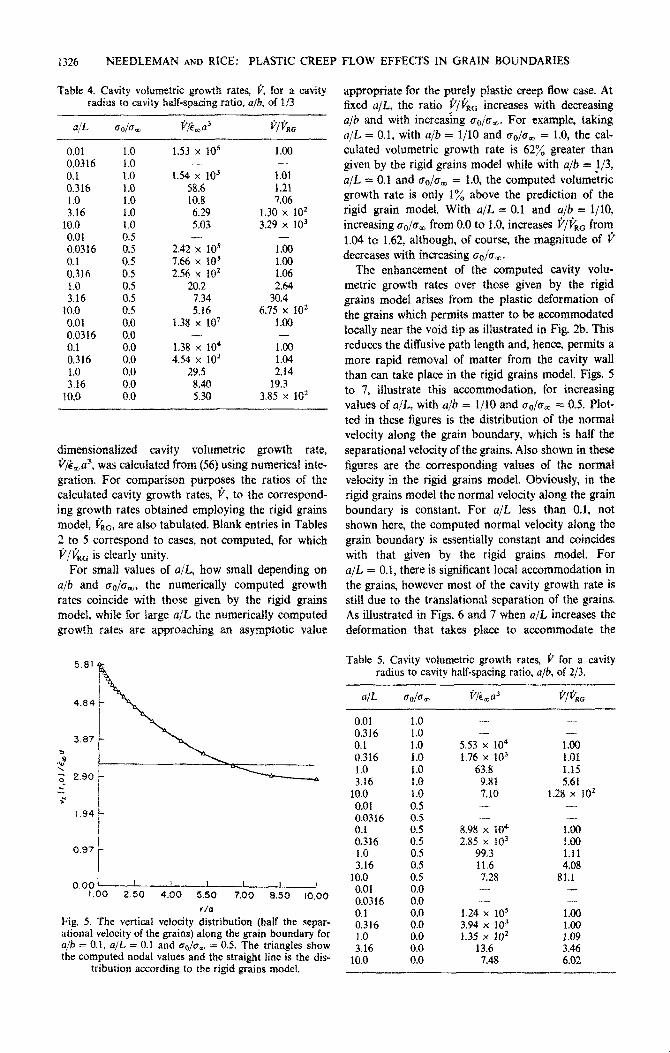
Fig. 5. The vertical velocity distribution (half the separ- ational velocity of the grains) along the grain boundary for ajb = 0.1, a/L = 0.1 and Q/U, = 0.5. The triangles show the computed nodal values and the straight line is the dis-
tribution according to the rigid grains modei.
FLOW EFFECTS IN GRAIN BOUNDARIES
appropriate for the purely plastic creep Aow case. At fixed a/L, the ratio p@& increases with decreasing a/b and with increasing (T&,. For example, taking a/L = 0.1, with a/b = l/l0 and uo/5m = 1.0, the cal- culated volumetric growth rate is 62% greater than given by the rigid grains model while with a/b = J/3, a/L = 0.1 and o&r, = 1.0, the computed volumetric growth rate is only 1% above the prediction of the rigid grain model. With a/L = 0.1 and a/b = l/10, increasing 6*,/a, from 0.0 to 1.0, increases P/P& from 1.04 to 1.62, although, of course, the magnitude of 3 decreases with increasing oO/rrm.
The ~han~ment of the computed cavity volu- metric growth rates over those given by the rigid grains model arises from the plastic deformation of the grains which permits matter to be accommodated locally near the void tip as illustrated in Fig. 2b. This reduces the diffusive path length and, hence, permits a more rapid removal of matter from the cavity wall than can take place in the rigid grains model. Figs. 5 to 7, illustrate this accommodation, for increasing values of a/L, with a/b = I/IO and a&, = 0.5. Plot- ted in these figures is the distribution of the normal velocity along the grain bound~y, which is half the separational velocity of the grains. Also shown in these figures are the ~orres~nding vatues of the normal velocity in the rigid grains model. Obviously, in the rigid grains model the normal velocity along the grain boundary is constant. For a/L less than 0.1, not shown here, the computed normal velocity along the grain boundary is essentially constant and coincides with that given by the rigid grains model. For a/L = 0.1, there is significant local accommodation in the grains, however most of the cavity growth rate is still due to the transIationa1 separation of the grains. As illustrated in Figs. 6 and 7 when a/L increases the deformation that takes place to accommodate the
Table 5. Cavity volumetric growth rates, P for a cavity radius to cavity half-spacing ratio, a/b? of 2/3.
ait @o/e,
0.01 1.0 0.316
::t: 0.1 0.316 1.0 1.0 1.0 3.16 1.0
10.0 1.0 0.01 OS 0.0316 0.5
%16 0.5
i:0 0.5 0.5
3.16 0.5 10.0 0.5 0.01
z 0.0316 0.1 0:o 0.316 1.0 :I:: 3.16
10.0 8::
l&(33
- -
5.53 x 10⁴ 1.76 x 10³
63.8 9.81 7.10 - -
898 x lo4 2.85 x 10³
99.3 11.6 7.28 - -
1.24 x 10; 3.94 x 10³ f.35 x 102
13.6 7.48
jj/ki
- -
1.00 1.01 1.15 5.61
1.28 x 10² - -
I.00 1.00 1.11 4.08
81.1 - - 1.00
:.: 3:46 6.02

NEEDLEMAN AND RICE: PLASTIC CREEP FLOW EFFECTS IN GRAIN BOUNDARIES 1327
I .46 0
%? \
3 I .09
>r
0.73
0.36
Fig. 6. The vertical velocity distribution (half the separational velocity of the grains) along the grain boundary for a/b = 0.1, a/L = 0.316 and U&J, = 0.5. The triangles show the computed nodal values
and the straight line is the distribution according to the rigid grains mode).
matter being transported from the cavity walls cavity volumetric growth rate takes the form
becomes more localized. Since the rigid body separa- tional velocity of the grains is decreasing as (Q/L)-~, the enhancement of the cavity growth rate due to this accommodation becomes more pronounced.
“Q 2rc(; - I)[(%) - 11 (63) Ecoa
The numerical results obtained here for the cavity where volumetric growth rate can be compared with the results of the approximate upper bound analysis of
1 4L3 Z/n
Edward and Ashby [lo]. Their upper bound on the p=z b3 ( )
0.00 i 1.00 2.50 4.00 5.50 7.00 0.50 10.00
r/o
Fig, 7. The vertical velocity distribution (half the separational velocity of the grains) along the grain boundary for a/b = 0.1, a/L = 1.0 and uo/o, = 0.5. The triangles show the computed nodal values. Here, the straight line giving the distribution according to the rigid grains model essentially coincides with
the horizontal axis on the scale of the figure.

1328 NEE~~EMAN AND RICE: PLASTIC CREEP
RIGID GRAINS \ MODEL <-’
I I \
/EDWARD AND ASHBY [IO]
c...-..--
L
I I _
-2.0 -1.0 0.0 I.0 2.0
lOqp/L1
Fig. 8. Log-log (base 10) plot of the cavity volumetric growth rate versus a/L for a/b = 0.1, and for extreme values of the ratio of the classical sintering limit stress to applied stress, ao/dm = 0.0 and uO/um = 1.0. For compari- son purposes the predictions of the rigid-grains model and the upper bound analysis of Edward and Ashby [lo] are
also shown.
and in obtaining (63), Edward and Ashby [lo] assume
Q,, negligible.
Figure 8 gives a log-log (base 10) plot of the com- puted normalized cavity volumetric growth rates versus a/L, for a/b = l/l0 and with Q/CT, = 0.0 and 1.0. The numerical results, plotted from the values in Table 2, are extrapolated past a/L = 10.0 in Fig. 8. Also plotted in this figure is the right hand side of (63). In the power law creep dominated regime the upper bound of Edward and Ashby [lo] is about a factor of six above the computed cavity growth rate. For example at a/L, = 10.0, (63) gives an upper bound of 34.3 while the numerical values of @,a3 range from 5.34 for a&r, = 0.0 to 5.10 for 6&r, = 1.0.
In the limit of essentially rigid grains behavior, a/L small or P large, (63) gives p/&a3 c (cJ/L)-~, whereas the rigid grains model, with which the numerical results coincide in this limit, gives 6’/k,a3 - (a/L)-3. Thus, for sufficiently small a/L, approximately aJL _ 10-2.5 in Fig. 8, (63) also gives an upper bound. In this regime the cavity growth rate as given by the rigid grains model, presumed valid in this limit, is significantly below the upper bound (63).
For intermediate values of u/L, where the coupling between grain boundary diffusion and plastic creep flow is significant, the right hand side of (63) falls
FLOW EFFECTS IN GRAIN BOUNDARIES
Fig. 9. Contours of constant effective creep strain rate, k = &, for a/b = 0.1, a,& = 0.316 and a&, = 0.5.
between the computed results for a&, = 1.0 and
oo/e, = 0.0. Hence, (63) is not a true upper bound. As mentioned in the Introduction, the analysis of
Edward and Ashby [lo] is based on the concept, introduced by Beere and Speight [9], of the cavity being surrounded by a shell of effectively non- creeping material. To explore the appropriateness of this concept in light of the present numerical solu- tions, Figs 9 to 11 exhibit contours of constant effec- tive creep strain rate for a/b = l/10, cro/o, = 0.5 and a/L = 0.316, 1.0 and 3.16 respectively. In these figures, the contours are curves of constant effective creep strain rate normalized by the remote effective creep strain rate.
Q.
Fig. -10. Contours of constant effective creep strain rate, E = &. for afb = 0.1, a/L = 1.0 and uO/a, = 0.5.

NEEDLEMAN AND RICE: PLASTIC CREEP FLOW EFFECTS IN GRAIN BOUNDARIES 1329
Fig.. 11. Contours of constant effective creep strain rate, E = C/ta, for u/b = 0.1, a/L = 3.16 and o,io, = 0.5.
In Fig. 9. where a/L = 0.316, the maximum effec- tive creep strain rate occurs at the cavity along the
axis of symmetry, and has a value of about E = 1.1.
Except for this small zone of plastic creep deforma- tion, the cavity is surrounded by a diffusionally
relaxed region, with the grain material outside this
relaxed region deforming nearly homogenously, with
the region bounded by k = 1.0 being a plateau on
which 1.0 5 i < 1.1. For a smaller value of a/L than
0.316, the contours of E exhibit a similarly shaped,
but larger, diffusionally relaxed region to that depicted in Fig. 9.
As a/L increases, in Figs. 10 and 11, the diffusion-
ally relaxed zone moves up from the grain boundary
and the plateau of effective creep strain rate becomes
more peaked and propagates toward the cavity tip.
Note also that the creep deformation zone along the cavity boundary near the axis of symmetry is relaxed.
In Figs. 5511 we have plotted features of the nu- merical results for a/b = l/10. Qualitatively similar
features, although differing in detail, were observed
for the other values of a/h considered.
As is evident from the results displayed so far, the numerical solution depend in a complex way on the
parameter a/L. In contrast, the dependence of the cavity volumetric growth rate on o,,/olo is surprisingly simple; the cavity volumetric growth rates displayed
in Tables 2 to 5 are linear in u&r,. Of course, such
linearity must emerge in the rigid grains limit. but there is no obvious reason (to us) why a linear re- lation should persist into the regime where the plastic creep flow effects are significant. As illustrated in Fig. 12, where each computed point is marked, the linear dependence of the cavity growth rate on uo/crcc covers the range from a&, = 0.0 to the sintering limit at which $’ vanishes for a/L = 0.316 and 1.0.
Denoting the value of u&r, at the sintering limit by
(c,,/c~~)~, the rigid grains approximation gives
(6&,), = [l - a2/b2] - l.
Linear extrapolation of the values of v/&a3 in
Table 2 for a/L = 0.01, 0.0316 and 0.1 all give (ao/om), = 1.01, in agreement with (64). However, from Fig. 12, (~~/a,), = 1.10 and 1.59 for a/L = 0.316
and 1.0 respectively. Although here we do not pursue, in detail, an inves-
tigation of the dependence of the sintering limit on
plastic creep flow, we note that a similar linear extra-
polation, to that above, carried out for a/L = 3.16
with (~~/a,) = 4.0 and 4.5 gave positive cavity volu-
metric growth rates, thereby illustrating that the linear dependence of i’/i,a3 exhibited in Tables 2 to 5
and Fig. 12 is not a general attribute of solutions of
(46). Indeed, as remarked previously, in the limit of
a/L large, solutions of (46) approach the pure power law creep solutions, for which $‘/&,,a3 is positive and
independent of a&~,. These considerations show that in the presence of
plastic creep flow the classical sintering limit of equa-
tion (64) is irrelevant if conditions are such that L is
comparable to or smaller in size than u. Voids then continue to grow even when the applied stress is less
than the classical limit.
7. ESTIMATE OF THE TIME TO RUPTURE
When fracture occurs by intergranular cavitation,
the time to rupture t,, and the steady-state creep rate, at a constant applied stress, i,,, are sometimes found
240
r
Fig. 12. Plot of the computed normalized cavity volu- metric growth rate versus CT~/U, for a/b = 0.1, a/L = 0.316
and a/L = 1.0.

PLASTIC CREEP FLOW EFFECTS IN GRAIN BOUNDARIES 1330 NEEDLEMAN AND RICE:
experimentally to be related by Monkm~-Grant [S] correlation
kSS t, = constant.
the well-known
(65)
Typically, &J, has a value in the range between 0.05 and 0.5.
The numerical results presented in the preceding section will be utilized to obtain an estimate of &t, under the assumption that the surface diffusion is suf- ficiently rapid to maintain the equilibrium spherical- caps cavity shape. We emphasize that the validity of this assumption, when plastic creep flow effects are significant, is an open question.
Here, we define the rupture time, t,, as the time for a cavity to grow from an initial radius, ai, to the limiting radius, b, at which there is coalescence. Thus, we neglect the ~ntribution to the rupture time of the time required to nucleate the cavities, which, in practical cases (see Raj and Ashby [16]), can be significant.
Differentiating (4) with respect to time and re- arranging terms gives
(66)
where, here, =& is properly identified with the re- motely imposed strain rate, i,, and the denominator on the right hand side of (66) is a function of the current values of a/b, aJL and QIC~ (here (r = Ai:/“).
Rather than directly evaluating the integral in (66), it proved convenient to adopt the following numerical procedure. The current time derivative of the cavity radius, C% is written, from (4), as
= _ru’, F(i, ;,ao,am) 4nW)
Here, C, is identified with i, and the appropriate value of F(a/b, aJL, a&J is chosen by interpolating between the values given in Tables 2-5. First, for the current value of a/b a table analogous to Tables 2-5 is constructed. This table is constructed by linear inter- polation of either &%,a3 or p/pRRc, whichever has the smallest relative change (change in the entry divided by the minimum of the entries in the two of Tables 2-5 employed in the interpolation). Then for those entries for which p/$“C is interpolated, p/&u3 is calculated by multiplying f$T$‘,, by v&&a3 where p,G is determined from (9). For example, if the current value of a/b is 0.15, the value of p/&a3 entered in the table for a/L = 0.1 and e&r, = 1.0 would be deter- mined by linear interpolation of p/p’o between 1.62 and 1.06, and then multiplying the interpolate value (1.34) by the value of i/,,/&u3 calculated, from (9), with a/b = 0.15, the value of @,a3 entered in the table for a/L = 1.0 and c&r, = 0.0 would be deter- mined by linearly interpolating between 27.3 and 27.6.
The second step consists of linearly interpolating between the two values of co/o, to give $‘/&,u3, at the current values of u/b and so/am, for a/L = 0.01, 0.0316---10.0. (For a/L > 10.0, it is assumed that the value of p/&a3 at aO/em = 1.0, a/L = 10.0 con- stitutes an adequate approximation to the plastic creep flow limit.) The third and final step employs linear interpolation of log,,(@‘/&,a3), considered as a function of log,&/L). Here, this logarithmic interpolation is employed, since as exhibited in Fig. 8, log&/&,a3) is a rather slowly varying function of log~~(~/L) for which linear interpolation can be expected to be reasonably accurate.
The value of d at the current time, t, is then readily calculated from (67). The value of cavity radius, a, at t + dt is given by [a(t) + ci dt] where dt is chosen so that [a(t) + ri dr] is equal to l.Ola. Then, the values of a/b, a/L and, from (lo), co are calculated and the whole procedure repeated. The calculation initiates at a = ai and terminates when a = b. In order to carry out the calculation for a/b > Z/3, the appropriate value of @&a3 is given by an extrapolation pro- cedure analogous to the linear interpolation pro- cedure described above. The final result is not par- ticularly sensitive to the details of the extrapolation scheme employed, since typically, 85% or more of the rupture time has elapsed when a/b = 2j3, for the cases considered here,
The final result gives i& as a function of b/L, q/b and (ao/a,)i. Results for c&t* as a function of b/L for various ratios of initial cavity radius to spacing with (ao/am)i = 0.0 and 1.0, are shown in Fig 13. Also shown in this figure, for comparison purposes, are the predictions of the model of Edward and Ashby ([lo] Fig. 9) for this case.
For small b/L, the cavity growth rate is purely dif- fusion controlled and, from (9), with which the nu- merical results agree (to within lx), in this limit for at/b = l/10,
b3 c&r, = 3.03 x 10⁻² -
0 L for (a(JCr,)i = 0.0
\ I
b 3 0 (68)
tt& = 5.02 x 10-z - L
for (a,/a,)t = 1.0
At the other limit, b/L large, the diffusional contri- bution to the cavity growth rate is negligible, ti/&,n3 is independent of (a,/a,)[ and nearly constant over most of the lifetime. Approximating this constant by 5.2 and carrying out the inte~ation in (66) gives,
&.t, Z 3.4 (69)
For intermediate values of ai/b, the values of I&, at fixed b/L, depends somewhat on (crO/em)i; for example, for b/L = 3.16, ci,t, = 0.38 and 0.52 for (co/a& = @O and 1.0, respectively. However, as can be seen in Fig. 13, the value of C,tV is a much more sensitive function of b/L than of (a,/a,)i, at least for the parameter values considered here.

NEEDLEMAN AND RICE: PLASTIC CREEP FLOW EFFECTS IN GRAIN BOUNDARIES 1331
---- op’b = 0.10 FROM [IO]
@ oi/b= 0.20 (rohm), = 0.0
@ ai/b = 0. IO (cG,/~;D), = 0.0
0 q/b= 0.05 (~r,/i&,)~ = 0.0
@ o$b=O.lO Lc~/q,)~ - 1.0
@ q/b = 0.05 (co/am)i - 1.0
2.0
1.6
0.4 ______ __------
4.0 6.0 6.0 10.0
b/L
Fig. 13. Plots of the Monkman-Grant product i-t,, where & is the remotely imposed strain rate (based on plastic dislocation creep only) and t, is the time to coalescence, vs b/L for various values of the initial cavity radius to spacing ratio ai/b and various ratios of the classical sintering limit
stress to applied stress (~~/a,)~.
The model of Edward and Ashby [IO] underesti- mates the value of i,t, in the regime where cavity growth takes place primarily by power law creep. This is consistent with the fact that their upper bound, as illustrated in Fig. 8, is about a factor of 6 greater than the numerical results in this regime. It shouid also be noted that the assumption, embodied in our calculation of the rupture time, as well as in that of Edward and Ashby [lo], that the cavity retains its equilibrium spherical-caps shape is particu- larly questionnable in this regime. For b/L 2 2 there is, as shown in Fig. 13, agreement between the predic- tions of the Edward and Ashby [lo] model and the present results. For very small b/L, say b/L < 10ml.
the residual rupture time, due to pure diffusional growth, is underestimated by their model. since it *‘*w a cavity growth rate that is greater than given by (9) in this limit, as discussed in reference to Fig. 8.
The results in Fig. 13 show that a Monkman-Grant correlation cannot be expected from considerations of cavity growth alone. Indeed, Miller [26] has recently emphasized the different stress dependencies for the growth rate of existing cavities, and for the total rup- ture time in clFe, attributing the difference to the time required for nucleation. However, in cases for which all or most of the lifetime to rupture involves cavity growth, the results in Fig. 13 suggest that values of the Monkman-Grant product in the representative range from approximately 0.05 to 0.5 will result for a wide range of b/L (from approximately 1 to 4) for
essentially al1 ratios of initial cavity size to spacing and of applied stress to the classical sintering limit. Further, the term i,, in Fig. 13 refers to the strain rate associated with plastic creep alone. Diffusional contri- butions to the overall steady creep rate become increasingly more important compared to plastic con- tributions at small values of b/L, and this will tend to make the actual value of the Monkman-Grant product somewhat higher than what we show in Fig. 13 for small hjL.
8. SUMMARY AND CONCLUSIONS
1. It has been shown that plastic creep flow inter- acts with diffusional processes of grain boundary cavity growth. The principal effect is that creep de- formability of the grains allows matter diffused from the cavity walls to be accommodated by local separ- ations of the adjoining grains in the vicinity of the cavity (Figs. 2b and 5 to 7), thus shortening the effec- tive diffusion path length and resulting in greater rates of cavity growth than would be the case if either grain boundary diffusion or plastic creep flow acted in isolation.
2. A quantitative analysis of the process has been based on a variational principle governing combined processes of plastic creep flow and grain boundary diffusion, employed as the basis of a finite-element numerical solution for the growth of a spherical-caps cavity of radius a, spaced at center-to-center distance 2h with neighboring cavities.
3. The resulting cavity growth rates are found to be greatly in excess of those based on the rigid grains (Hull-Rimmer) model, Tables 2 to 5 and Fig. 8. when- ever the stress and temperature dependent parameter L is of a size comparable to or smaller than the cavity radius U.
4. Values of the parameter L are presented in Table 1 and suggest. e.g., that at 0.5 T, the coupling between plastic creep and diffusion will generally be significant at stresses of the order 10e3 p or higher. but not at stresses of the order 10e4p or lower. L decreases in size with increasing stress and/or tem- perature.
5. The patterns of the Mises equivalent shear strain rate distribution presented in Figs. 9 to 11 do not support closely the concept of a non-deforming spherical zone adjoining the cavity and embedded in a cage of plastically deforming material, although more complexly shaped zones of effectively non- deforming material do result immediately above and below the cavity.
6. In the presence of overall plastic creep flow. cavi- ties continue to grow (Fig. 12) even at applied stress levels which are somewhat less than the classical sin- tering limit. The effect is most pronounced for values of a/L of the order unity or larger.
7. Integration of the cavity growth rate equations leads to predictions of rupture times t, based on growth alone (i.e., ignoring nucleation), which are

1332 NEEDLEMAN AND RICE: PLASTIC CREEP FLOW EFFECTS IN GRAIN BOUNDARIES
such that the Monkman-Grant product &t, varies with stress level and temperature, for a given initial cavity size ai and half spacing b (Fig. 13).
8. The analysis is based on the assumption that surface diffusion is sufficiently rapid to retain a quasi- equilibrium type of spherical-caps cavity shape. The range of validity of this assumption will certainly be limited, especially in low-L cases for which rapid cavity growth is predicted. This is an important topic for further study. Also, elastic and transient creep be- havior of the grains has been neglected. These are expected to be important following alterations of load level, although not for long-time sustained loading.
Acknowledgements-This study was supported by the U.S. Department of Energy under contract EY-76-02-3084.AOOl with Brown University. We are grateful to Professor M. F. Ashby for helpful discussions and for the communication of materials data, and to Mr. A. Rubenstein for assistance in the preparation of Table 1.
REFERENCES
1. D. Hull and D. E. Rimmer, Phil. Mug. 4, 673 (1959). 2. M. V. Speight and J. E. Harris, Metal. Sci. J. 1, 83
(1967). 3. J. Weertman. Scripta Metall. 7, 1129 (1973). 4. T-J. Chuang and J. R. Rice, Acta Metal/. 23, 425
(1973). 5. T-J. Chuang, K. I. Kagawa, J. R. Rice and L. B. Sills,
Acta Metall. 27, 265 (1979).
6. 7. 8.
9. 10.
11.
12. 13. 14.
15.
T-J. Chuang, Ph.D. Thesis, Brown University (1974). V. Vitek. Acta Metall. 26. (1978). F. C. Monkman and N. J. ‘Grant. Proc. ASTM 56, 593 (1956). W. Beere and M. V. Speight, Metal Sci. 4, 172 (1978). G. H. Edward and M. F. Ashby, Acta Metall. 27, 1505 (1979). J. R. Rice, Time Dependent Fracture of Materials at Elenated Temperature (edited by S. Wolf). p. 130. U.S. Department of Energy Report CONF 790236 UC-25, Germantown, Md. (June 1979). J. Weertman, Metal/. Trans. 5, 1743 (1974). J. W. Hancock, Metal Sci. 10, 319 (1976). B. Budiansky and R. J. O’Connell, Int. J. So/ids Struct. 12, 81 (1976). J. R. Rice and T-J. Chuang, J. Am. Ceram. Sot. in press.
16. R. Raj and M. F. Ashby, Acta Metall. 23, 653 (1975). 17. R. Raj, H. M. Shih and H. H. Johnson, Scripta Metall.
11, 839 (1977). 18. H. J. Frost and M. F. Ashby, privately communicated
compilation of high temperature creep and diffusion data (1979).
19. A. Needleman and C. F. Shih, Camp. meth. uppl. Mech. Engng 15, 223 (1978).
20. C. Herring, Structure and Properties of So/id Surfaces (edited by R. Gomer and C. S. Smith), Univ. of Chicago Press (1952).
21. C. Herring, The Physics of Powder Metallurgy, p. 143 (edited by W. E. Kingston), McGraw-Hill (1951).
22. M. F. Ashby, Acta Metall. 20, 887 (1972). 23. S. H. Goods and W. D. Nix, Acta Metall. 26, 739
(1978). 24. S. H. Goods, Ph.D. Thesis, Stanford University (1977). 25. R. Raj, Acta Metall. 26, 341 (1978). 26. D. A. Miller, Scripta Metall. 13, 595 (1979).