overview brochure - kent introl · pdf fileoverview brochure koso kent introl supplies a ......
TRANSCRIPT
OVERVIEW BROCHURE
kentintrol
SCOPE OF DESIGNKKI specialises in the supply ofhigh-technology surface choke valves,standard and severe-service controlvalves and rotary valves for the oil andgas, petrochemical and power industries.Complementing these products is the KKIrange of actuators and instrumentation.
We have built a reputation for supplyingspecially designed high quality valves forthe most demanding service conditions. Itmeans that we can offer tried and testedvalve solutions for problematicapplications relating to cavitation,flashing, erosion, high velocity, noiseand vibration, as well as for processesthat involve high pressures, hightemperatures, sub-zero temperatures orsolid-contaminated fluids.
Valves are manufactured using a rangeof materials, from carbon steel to nickelalloys and high strength super-austeniticmaterial. Innovative trims are a crucialelement in overcoming the operationalconditions encountered in manyapplications, with advanced designsbeing developed by our engineers tohandle a whole host of pressure,temperature and velocity situations.
Among our range of high performancetrims, we offer a multi-turn labyrinth trimdesign, specifically designed to preventcavitation erosion, high vibration and noise.
QUALITY MANUFACTURINGMaintaining the highest standards ofquality throughout design, productionand customer service is the cornerstoneof KKI’s philosophy.
Our facility is accredited in accordancewith Quality Management System ISO9001, Environmental ManagementSystem ISO 14001 and Oil and GasSystem ISO 29001. In addition allproducts, where applicable, conform toATEX, PED and all other applicable EUdirectives and are ---- markedaccordingly.
OVERVIEWBROCHURE
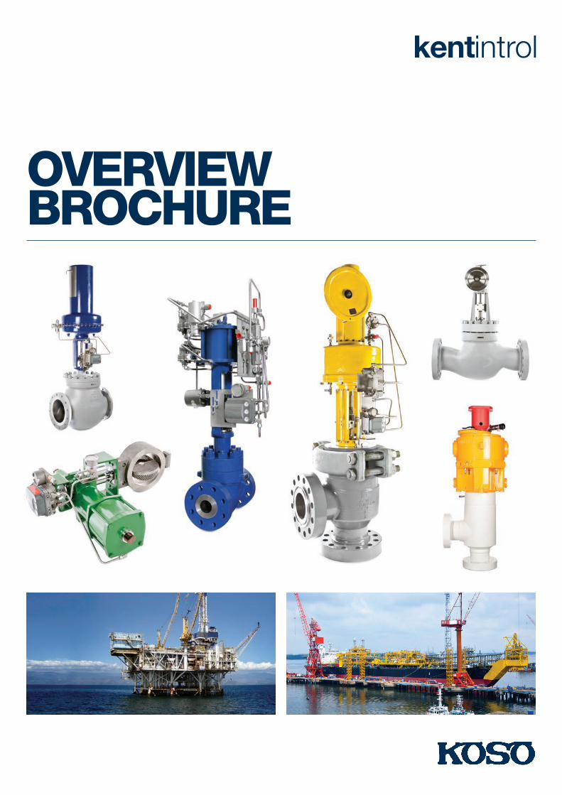
KOSO KENT INTROL SUPPLIES ADIVERSE RANGE OF PRECISION–MANUFACTURED CHOKE, CONTROLAND ROTARY VALVES FOR OIL ANDGAS, PETROCHEMICAL AND POWERINDUSTRIES, WORLDWIDE
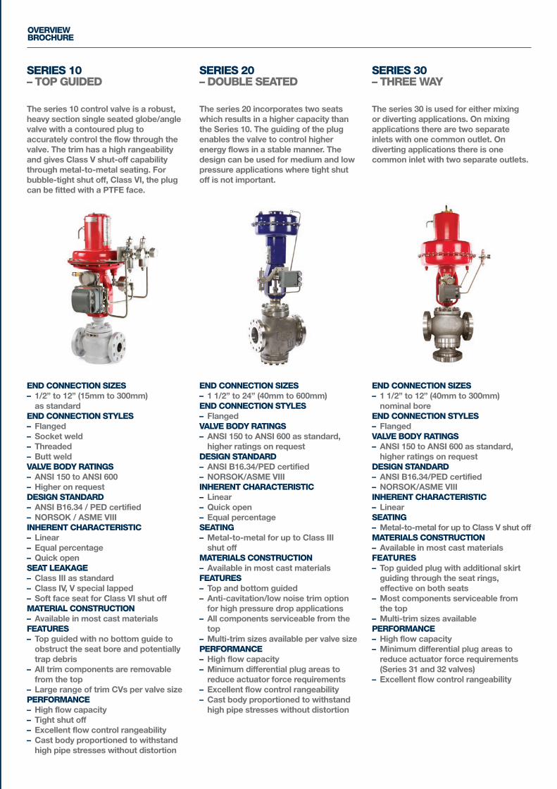
The series 10 control valve is a robust,heavy section single seated globe/anglevalve with a contoured plug toaccurately control the flow through thevalve. The trim has a high rangeabilityand gives Class V shut-off capabilitythrough metal-to-metal seating. Forbubble-tight shut off, Class VI, the plugcan be fitted with a PTFE face.
The series 20 incorporates two seatswhich results in a higher capacity thanthe Series 10. The guiding of the plugenables the valve to control higherenergy flows in a stable manner. Thedesign can be used for medium and lowpressure applications where tight shutoff is not important.
The series 30 is used for either mixingor diverting applications. On mixingapplications there are two separateinlets with one common outlet. Ondiverting applications there is onecommon inlet with two separate outlets.
END CONNECTION SIZES– 1/2” to 12” (15mm to 300mm)as standard
END CONNECTION STYLES– Flanged– Socket weld– Threaded– Butt weldVALVE BODY RATINGS– ANSI 150 to ANSI 600– Higher on requestDESIGN STANDARD– ANSI B16.34 / PED certified– NORSOK / ASME VIIIINHERENT CHARACTERISTIC– Linear– Equal percentage– Quick openSEAT LEAKAGE– Class III as standard– Class IV, V special lapped– Soft face seat for Class VI shut offMATERIAL CONSTRUCTION– Available in most cast materialsFEATURES– Top guided with no bottom guide toobstruct the seat bore and potentiallytrap debris
– All trim components are removablefrom the top
– Large range of trim CVs per valve sizePERFORMANCE– High flow capacity– Tight shut off– Excellent flow control rangeability– Cast body proportioned to withstandhigh pipe stresses without distortion
END CONNECTION SIZES– 1 1/2” to 24” (40mm to 600mm)END CONNECTION STYLES– FlangedVALVE BODY RATINGS– ANSI 150 to ANSI 600 as standard,higher ratings on request
DESIGN STANDARD– ANSI B16.34/PED certified– NORSOK/ASME VIIIINHERENT CHARACTERISTIC– Linear– Quick open– Equal percentageSEATING– Metal-to-metal for up to Class III shut off
MATERIALS CONSTRUCTION– Available in most cast materialsFEATURES– Top and bottom guided– Anti-cavitation/low noise trim optionfor high pressure drop applications
– All components serviceable from thetop
– Multi-trim sizes available per valve sizePERFORMANCE– High flow capacity– Minimum differential plug areas toreduce actuator force requirements
– Excellent flow control rangeability– Cast body proportioned to withstandhigh pipe stresses without distortion
END CONNECTION SIZES– 1 1/2” to 12” (40mm to 300mm) nominal bore
END CONNECTION STYLES– FlangedVALVE BODY RATINGS– ANSI 150 to ANSI 600 as standard,higher ratings on request
DESIGN STANDARD– ANSI B16.34/PED certified– NORSOK/ASME VIIIINHERENT CHARACTERISTIC– LinearSEATING– Metal-to-metal for up to Class V shut offMATERIALS CONSTRUCTION– Available in most cast materialsFEATURES– Top guided plug with additional skirtguiding through the seat rings,effective on both seats
– Most components serviceable fromthe top
– Multi-trim sizes availablePERFORMANCE– High flow capacity– Minimum differential plug areas toreduce actuator force requirements(Series 31 and 32 valves)
– Excellent flow control rangeability
OVERVIEWBROCHURE
SERIES 10 – TOP GUIDED
SERIES 20 – DOUBLE SEATED
SERIES 30 – THREE WAY
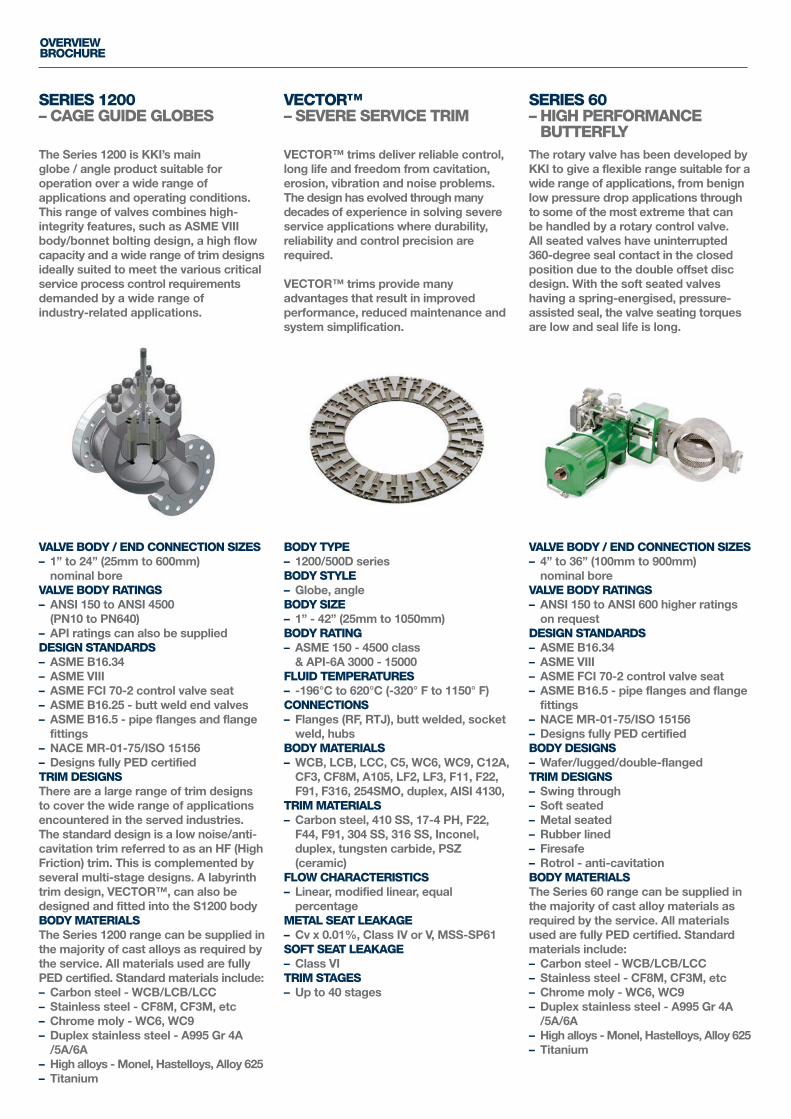
The Series 1200 is KKI’s main globe / angle product suitable foroperation over a wide range ofapplications and operating conditions.This range of valves combines high-integrity features, such as ASME VIIIbody/bonnet bolting design, a high flowcapacity and a wide range of trim designsideally suited to meet the various criticalservice process control requirementsdemanded by a wide range of industry-related applications.
VECTOR™ trims deliver reliable control,long life and freedom from cavitation,erosion, vibration and noise problems.The design has evolved through manydecades of experience in solving severeservice applications where durability,reliability and control precision arerequired.
VECTOR™ trims provide manyadvantages that result in improvedperformance, reduced maintenance andsystem simplification.
The rotary valve has been developed byKKI to give a flexible range suitable for awide range of applications, from benignlow pressure drop applications throughto some of the most extreme that canbe handled by a rotary control valve. All seated valves have uninterrupted 360-degree seal contact in the closedposition due to the double offset discdesign. With the soft seated valveshaving a spring-energised, pressure-assisted seal, the valve seating torquesare low and seal life is long.
VALVE BODY / END CONNECTION SIZES– 1” to 24” (25mm to 600mm) nominal bore
VALVE BODY RATINGS– ANSI 150 to ANSI 4500(PN10 to PN640)
– API ratings can also be suppliedDESIGN STANDARDS– ASME B16.34– ASME VIII– ASME FCI 70-2 control valve seat– ASME B16.25 - butt weld end valves– ASME B16.5 - pipe flanges and flangefittings
– NACE MR-01-75/ISO 15156– Designs fully PED certifiedTRIM DESIGNSThere are a large range of trim designsto cover the wide range of applicationsencountered in the served industries.The standard design is a low noise/anti-cavitation trim referred to as an HF (HighFriction) trim. This is complemented byseveral multi-stage designs. A labyrinthtrim design, VECTOR™, can also bedesigned and fitted into the S1200 bodyBODY MATERIALSThe Series 1200 range can be supplied inthe majority of cast alloys as required bythe service. All materials used are fullyPED certified. Standard materials include:– Carbon steel - WCB/LCB/LCC– Stainless steel - CF8M, CF3M, etc– Chrome moly - WC6, WC9– Duplex stainless steel - A995 Gr 4A/5A/6A
– High alloys - Monel, Hastelloys, Alloy 625– Titanium
BODY TYPE– 1200/500D seriesBODY STYLE– Globe, angleBODY SIZE– 1” - 42” (25mm to 1050mm)BODY RATING– ASME 150 - 4500 class & API-6A 3000 - 15000
FLUID TEMPERATURES– -196°C to 620°C (-320° F to 1150° F)CONNECTIONS– Flanges (RF, RTJ), butt welded, socketweld, hubs
BODY MATERIALS– WCB, LCB, LCC, C5, WC6, WC9, C12A,CF3, CF8M, A105, LF2, LF3, F11, F22,F91, F316, 254SMO, duplex, AISI 4130,
TRIM MATERIALS– Carbon steel, 410 SS, 17-4 PH, F22,F44, F91, 304 SS, 316 SS, Inconel,duplex, tungsten carbide, PSZ(ceramic)
FLOW CHARACTERISTICS– Linear, modified linear, equalpercentage
METAL SEAT LEAKAGE– Cv x 0.01%, Class IV or V, MSS-SP61SOFT SEAT LEAKAGE– Class VITRIM STAGES– Up to 40 stages
VALVE BODY / END CONNECTION SIZES– 4” to 36” (100mm to 900mm) nominal bore
VALVE BODY RATINGS– ANSI 150 to ANSI 600 higher ratingson request
DESIGN STANDARDS– ASME B16.34– ASME VIII– ASME FCI 70-2 control valve seat– ASME B16.5 - pipe flanges and flangefittings
– NACE MR-01-75/ISO 15156– Designs fully PED certifiedBODY DESIGNS– Wafer/lugged/double-flangedTRIM DESIGNS– Swing through– Soft seated– Metal seated– Rubber lined– Firesafe– Rotrol - anti-cavitationBODY MATERIALSThe Series 60 range can be supplied inthe majority of cast alloy materials asrequired by the service. All materialsused are fully PED certified. Standardmaterials include:– Carbon steel - WCB/LCB/LCC– Stainless steel - CF8M, CF3M, etc– Chrome moly - WC6, WC9– Duplex stainless steel - A995 Gr 4A/5A/6A
– High alloys - Monel, Hastelloys, Alloy 625– Titanium
OVERVIEWBROCHURE
SERIES 1200– CAGE GUIDE GLOBES
VECTOR™ – SEVERE SERVICE TRIM
SERIES 60– HIGH PERFORMANCE BUTTERFLY
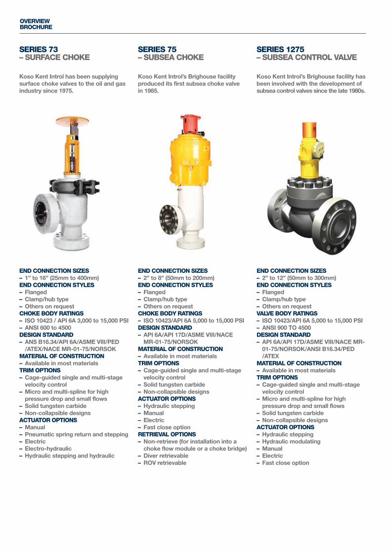
Koso Kent Introl has been supplyingsurface choke valves to the oil and gasindustry since 1975.
Koso Kent Introl’s Brighouse facilityproduced its first subsea choke valvein 1985.
Koso Kent Introl’s Brighouse facility hasbeen involved with the development ofsubsea control valves since the late 1980s.
END CONNECTION SIZES– 1” to 16” (25mm to 400mm)END CONNECTION STYLES– Flanged– Clamp/hub type– Others on requestCHOKE BODY RATINGS– ISO 10423 / API 6A 3,000 to 15,000 PSI– ANSI 600 to 4500DESIGN STANDARD– ANS B16.34/API 6A/ASME VIII/PED/ATEX/NACE MR-01-75/NORSOK
MATERIAL OF CONSTRUCTION– Available in most materialsTRIM OPTIONS– Cage-guided single and multi-stagevelocity control
– Micro and multi-spline for highpressure drop and small flows
– Solid tungsten carbide– Non-collapsible designsACTUATOR OPTIONS– Manual– Pneumatic spring return and stepping– Electric– Electro-hydraulic– Hydraulic stepping and hydraulic
END CONNECTION SIZES– 2” to 8” (50mm to 200mm)END CONNECTION STYLES– Flanged– Clamp/hub type– Others on requestCHOKE BODY RATINGS– ISO 10423/API 6A 5,000 to 15,000 PSIDESIGN STANDARD– API 6A/API 17D/ASME VIII/NACEMR-01-75/NORSOK
MATERIAL OF CONSTRUCTION– Available in most materialsTRIM OPTIONS– Cage-guided single and multi-stagevelocity control
– Solid tungsten carbide– Non-collapsible designsACTUATOR OPTIONS– Hydraulic stepping– Manual– Electric– Fast close optionRETRIEVAL OPTIONS– Non-retrieve (for installation into achoke flow module or a choke bridge)
– Diver retrievable– ROV retrievable
END CONNECTION SIZES– 2” to 12” (50mm to 300mm)END CONNECTION STYLES– Flanged– Clamp/hub type– Others on requestVALVE BODY RATINGS– ISO 10423/API 6A 5,000 to 15,000 PSI– ANSI 900 TO 4500DESIGN STANDARD– API 6A/API 17D/ASME VIII/NACE MR-01-75/NORSOK/ANSI B16.34/PED/ATEX
MATERIAL OF CONSTRUCTION– Available in most materialsTRIM OPTIONS– Cage-guided single and multi-stagevelocity control
– Micro and multi-spline for highpressure drop and small flows
– Solid tungsten carbide– Non-collapsible designsACTUATOR OPTIONS– Hydraulic stepping– Hydraulic modulating– Manual– Electric– Fast close option
OVERVIEWBROCHURE
SERIES 73 – SURFACE CHOKE
SERIES 75 – SUBSEA CHOKE
SERIES 1275– SUBSEA CONTROL VALVE
HF – HIGH FRICTION TRIMFor liquid, flows ‘over’ the plug are preferred. In this case theflow is split into many radial jets and, as the flow passesthrough the cage, the jets impinge upon themselves within theconfines of the cage. This is where the erosion forces will be attheir highest and where most of the flow energy can bedissipated. The flow then exits the trim through the valve seat.This means the valve body is protected from the effects of flowerosion. A trim manufactured from harder materials is morecapable of handling these erosion forces. On more severeapplications (high-pressure drop, contaminated fluids, etc), the trim’s operational life can be maintained by using overlayssuch as stellite or tungsten carbide inserts.
On gas/vapour services, the preferred flow direction is ‘under’the plug. The main reason for this is that it has been shown thatthe acoustic efficiency is lower in this direction. This reductionis attributed to the smaller scale turbulence structure andhigher frequency of the flow turbulence, resulting in a greaterlevel of attenuation from the downstream pipe work. Thisresults in a lower transmitted noise on HF trim designs. On theHF family of trims, noise reduction of between 15 to 20dBA canbe achieved over a conventional contoured/ported trim. Incases where further noise reduction is required, smaller holes,i.e. 3 or 4mm can be utilised in the cage. This can result infurther attenuation between 3 to 10dBA.
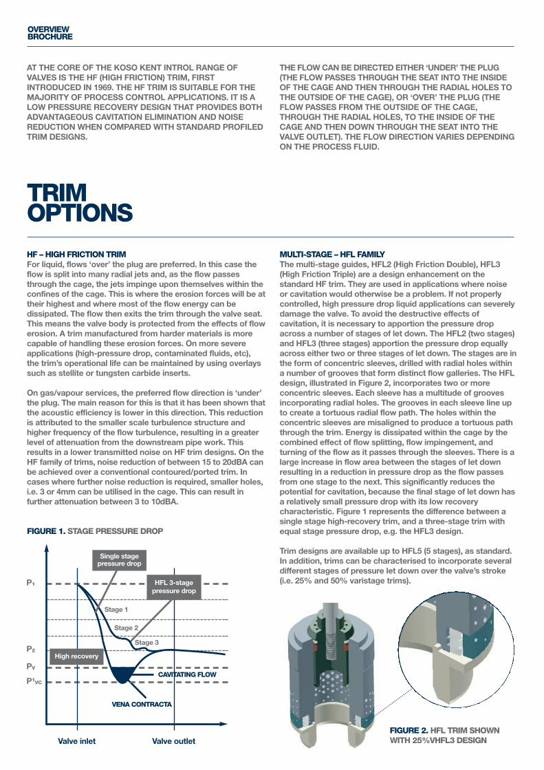
MULTI-STAGE – HFL FAMILYThe multi-stage guides, HFL2 (High Friction Double), HFL3(High Friction Triple) are a design enhancement on thestandard HF trim. They are used in applications where noise or cavitation would otherwise be a problem. If not properlycontrolled, high pressure drop liquid applications can severelydamage the valve. To avoid the destructive effects ofcavitation, it is necessary to apportion the pressure dropacross a number of stages of let down. The HFL2 (two stages)and HFL3 (three stages) apportion the pressure drop equallyacross either two or three stages of let down. The stages are inthe form of concentric sleeves, drilled with radial holes within a number of grooves that form distinct flow galleries. The HFLdesign, illustrated in Figure 2, incorporates two or moreconcentric sleeves. Each sleeve has a multitude of groovesincorporating radial holes. The grooves in each sleeve line upto create a tortuous radial flow path. The holes within theconcentric sleeves are misaligned to produce a tortuous paththrough the trim. Energy is dissipated within the cage by thecombined effect of flow splitting, flow impingement, andturning of the flow as it passes through the sleeves. There is alarge increase in flow area between the stages of let downresulting in a reduction in pressure drop as the flow passesfrom one stage to the next. This significantly reduces thepotential for cavitation, because the final stage of let down hasa relatively small pressure drop with its low recoverycharacteristic. Figure 1 represents the difference between asingle stage high-recovery trim, and a three-stage trim withequal stage pressure drop, e.g. the HFL3 design.
Trim designs are available up to HFL5 (5 stages), as standard.In addition, trims can be characterised to incorporate severaldifferent stages of pressure let down over the valve’s stroke(i.e. 25% and 50% varistage trims).
AT THE CORE OF THE KOSO KENT INTROL RANGE OFVALVES IS THE HF (HIGH FRICTION) TRIM, FIRSTINTRODUCED IN 1969. THE HF TRIM IS SUITABLE FOR THEMAJORITY OF PROCESS CONTROL APPLICATIONS. IT IS ALOW PRESSURE RECOVERY DESIGN THAT PROVIDES BOTHADVANTAGEOUS CAVITATION ELIMINATION AND NOISEREDUCTION WHEN COMPARED WITH STANDARD PROFILEDTRIM DESIGNS.
THE FLOW CAN BE DIRECTED EITHER ‘UNDER’ THE PLUG (THE FLOW PASSES THROUGH THE SEAT INTO THE INSIDEOF THE CAGE AND THEN THROUGH THE RADIAL HOLES TOTHE OUTSIDE OF THE CAGE), OR ‘OVER’ THE PLUG (THEFLOW PASSES FROM THE OUTSIDE OF THE CAGE,THROUGH THE RADIAL HOLES, TO THE INSIDE OF THECAGE AND THEN DOWN THROUGH THE SEAT INTO THEVALVE OUTLET). THE FLOW DIRECTION VARIES DEPENDINGON THE PROCESS FLUID.
TRIMOPTIONS
OVERVIEWBROCHURE
P1
PV
P2
P1VC
Stage 1
Stage 2
Valve inlet Valve outlet
Stage 3
CAVITATING FLOW
FIGURE 1. STAGE PRESSURE DROP
VENA CONTRACTA
FIGURE 2. HFL TRIM SHOWNWITH 25%VHFL3 DESIGN
Single stagepressure drop
HFL 3-stagepressure drop
High recovery
Through our dedicated service department we offer servicing,overhaul, spare parts supply and upgrade services for valves,chokes and associated instrumentation. Our skilled engineerswill overhaul and service valves at our fully equipped workshopin the UK, or on customers’ sites – around the world.
WE TAKE CARE OF EVERYTHINGOur team takes full ownership of every project, managingeverything from scoping the requirements, transportation and all servicing work, to testing, certification, dispatch andrecommendations for future maintenance. It means thatworking with KKI is simple and hassle-free, with all workcarried out efficiently by an experienced team to guaranteedquality standards. Based at our UK headquarters, our flexible,highly motivated and well-qualified service team offers a full range of service support, from commissioning newequipment, routine maintenance and trim overhauls to fullvalve overhauls and testing.
ANY JOB, ANY SIZE, ANYWHERENo job is too large or small for our experienced team. Whether you have a single valve that needs servicing or morethan 100 valves requiring a complete overhaul, we have theresources, skills and experience to complete your jobefficiently, expertly and on time.
INTERNATIONALLY RECOGNISED QUALIFICATIONSOur service team is fully qualified for UK and internationalwork, and will travel across the world to customer sites, asrequired. What’s more, our engineers are offshore certified tostringent Norwegian standards.
RAPID-RESPONSE SERVICEThe team can be mobilised the same day for UK services orwithin 24 hours for international requirements, subject toengineer availability. We have dedicated vehicles for sitevisits, fully equipped with emergency stocks and tooling.
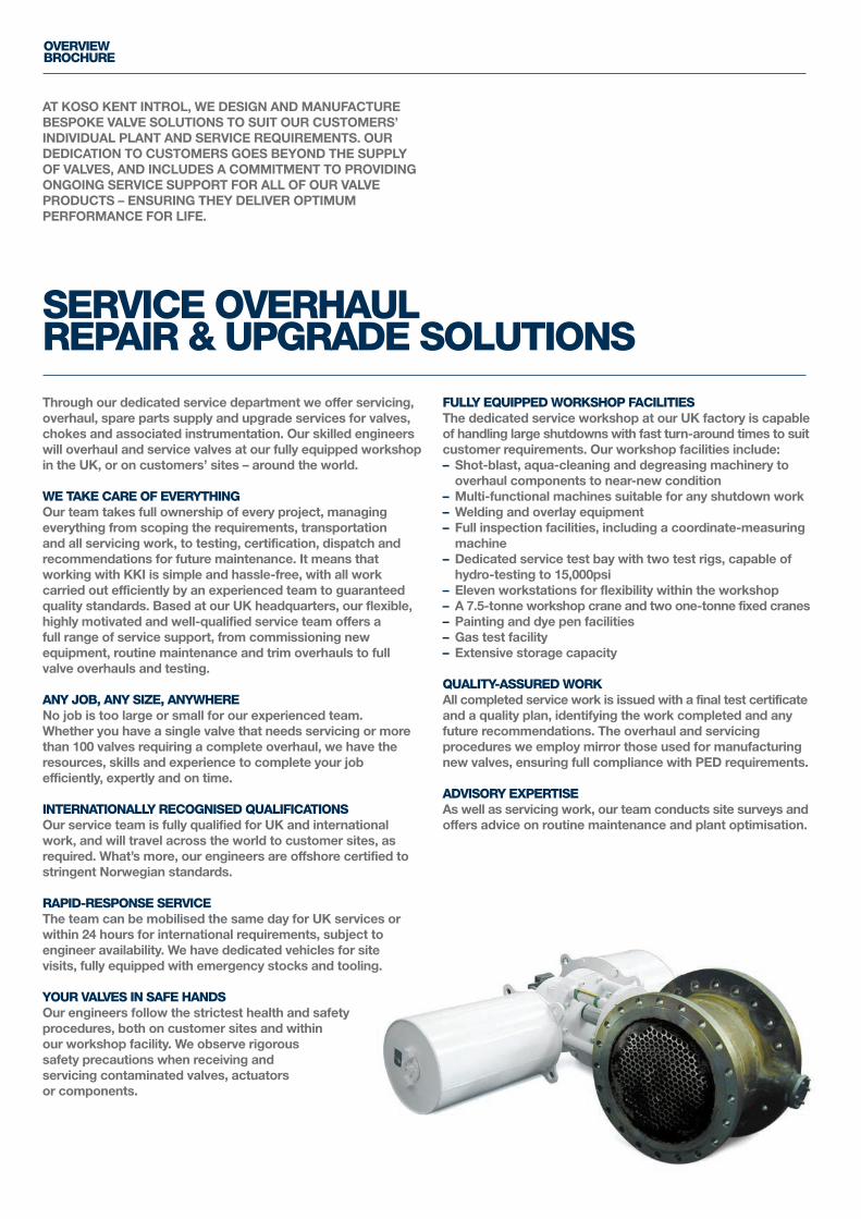
YOUR VALVES IN SAFE HANDSOur engineers follow the strictest health and safetyprocedures, both on customer sites and withinour workshop facility. We observe rigoroussafety precautions when receiving andservicing contaminated valves, actuatorsor components.
FULLY EQUIPPED WORKSHOP FACILITIESThe dedicated service workshop at our UK factory is capableof handling large shutdowns with fast turn-around times to suitcustomer requirements. Our workshop facilities include:– Shot-blast, aqua-cleaning and degreasing machinery tooverhaul components to near-new condition
– Multi-functional machines suitable for any shutdown work– Welding and overlay equipment– Full inspection facilities, including a coordinate-measuringmachine
– Dedicated service test bay with two test rigs, capable ofhydro-testing to 15,000psi
– Eleven workstations for flexibility within the workshop– A 7.5-tonne workshop crane and two one-tonne fixed cranes– Painting and dye pen facilities– Gas test facility– Extensive storage capacity
QUALITY-ASSURED WORKAll completed service work is issued with a final test certificateand a quality plan, identifying the work completed and anyfuture recommendations. The overhaul and servicingprocedures we employ mirror those used for manufacturingnew valves, ensuring full compliance with PED requirements.
ADVISORY EXPERTISEAs well as servicing work, our team conducts site surveys andoffers advice on routine maintenance and plant optimisation.
AT KOSO KENT INTROL, WE DESIGN AND MANUFACTUREBESPOKE VALVE SOLUTIONS TO SUIT OUR CUSTOMERS’INDIVIDUAL PLANT AND SERVICE REQUIREMENTS. OURDEDICATION TO CUSTOMERS GOES BEYOND THE SUPPLYOF VALVES, AND INCLUDES A COMMITMENT TO PROVIDINGONGOING SERVICE SUPPORT FOR ALL OF OUR VALVEPRODUCTS – ENSURING THEY DELIVER OPTIMUMPERFORMANCE FOR LIFE.
SERVICE OVERHAULREPAIR & UPGRADE SOLUTIONS
OVERVIEWBROCHURE
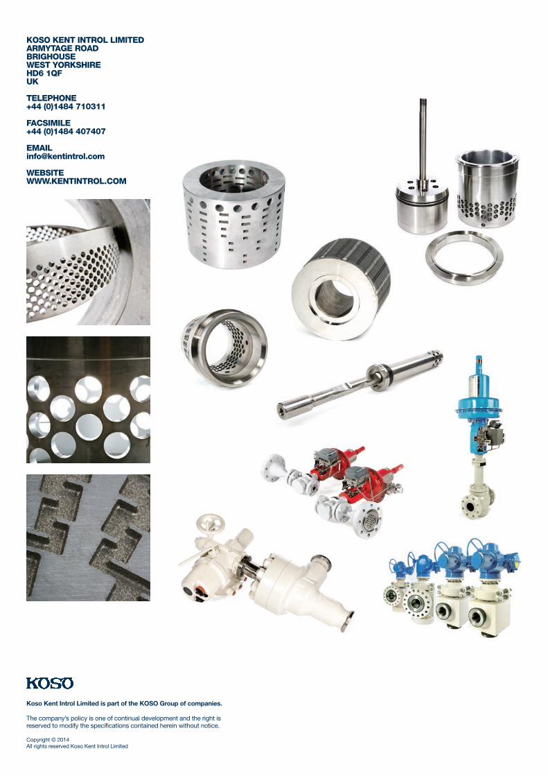
KOSO KENT INTROL LIMITEDARMYTAGE ROADBRIGHOUSEWEST YORKSHIREHD6 1QFUK
TELEPHONE+44 (0)1484 710311
FACSIMILE+44 (0)1484 407407
WEBSITE WWW.KENTINTROL.COM
Koso Kent Introl Limited is part of the KOSO Group of companies.
The company’s policy is one of continual development and the right isreserved to modify the specifications contained herein without notice.
Copyright © 2014All rights reserved Koso Kent Introl Limited