ovee - californiaaccentlighting.net · (lled8600-ucs).79”.45” 1.0”.50” clear lens (cl) 50%...
TRANSCRIPT
Page 1 of 19
INSTALLATION
Overview
LLED8600-UCS
2020.2.5 Rev 1
CALIFORNIA ACCENT LIGHTING, INC.2820 E. Gretta Lane, Anaheim, CA 92806ph. 800.921.CALI (2254) | fx. 714.535.7902 | [email protected] | calilighting.com© CALI. All rights reserved. CALI reserves the right to make changes or withdraw specifications without prior notice.
lipLEDs™RGBW
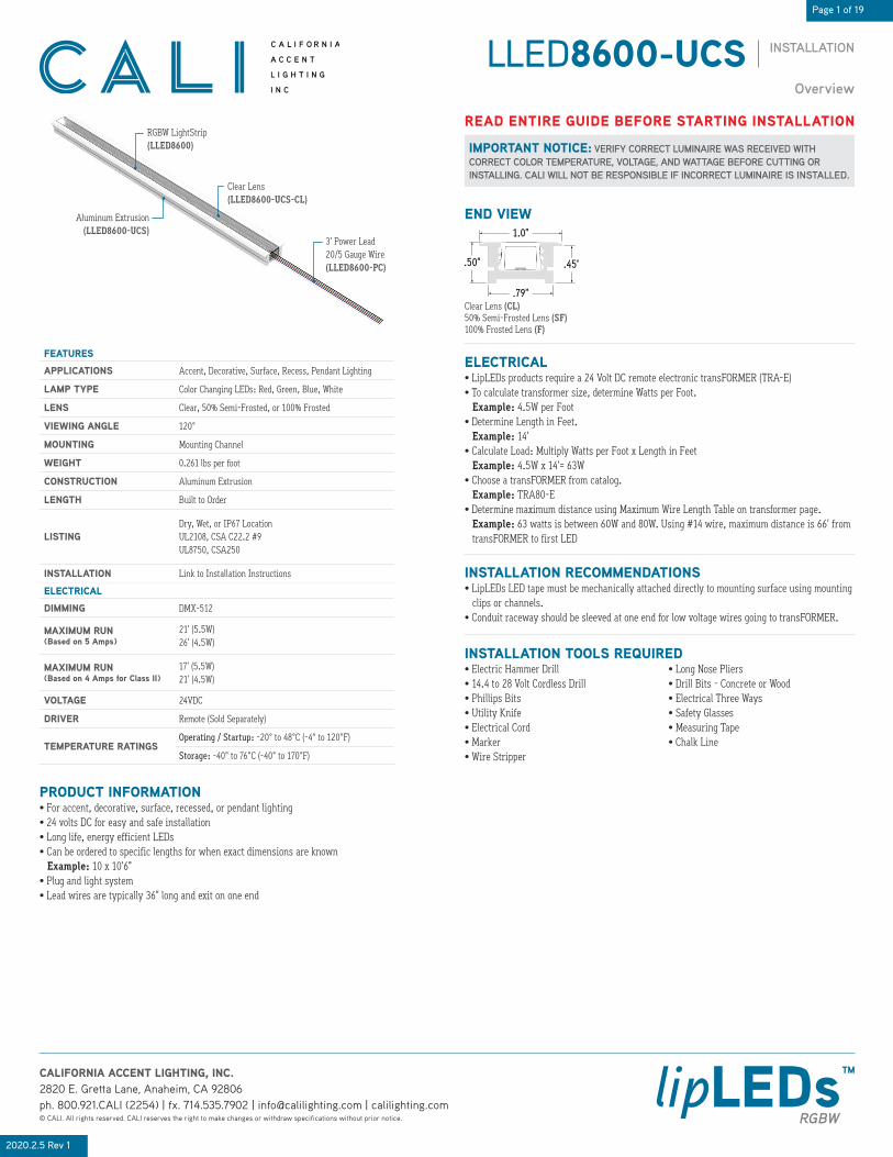
END VIEW
RGBW LightStrip(LLED8600)
3’ Power Lead20/5 Gauge Wire(LLED8600-PC)
Clear Lens(LLED8600-UCS-CL)
Aluminum Extrusion(LLED8600-UCS)
.79”
.45”
1.0”
.50”
Clear Lens (CL)50% Semi-Frosted Lens (SF)100% Frosted Lens (F)
IMPORTANT NOTICE: VERIFY CORRECT LUMINAIRE WAS RECEIVED WITH CORRECT COLOR TEMPERATURE, VOLTAGE, AND WATTAGE BEFORE CUTTING OR INSTALLING. CALI WILL NOT BE RESPONSIBLE IF INCORRECT LUMINAIRE IS INSTALLED.
READ ENTIRE GUIDE BEFORE STARTING INSTALLATION
FEATURES
APPLICATIONS Accent, Decorative, Surface, Recess, Pendant Lighting
LAMP TYPE Color Changing LEDs: Red, Green, Blue, White
LENS
VIEWING ANGLE
MOUNTING
WEIGHT
CONSTRUCTION
LENGTH Built to Order
LISTINGDry, Wet, or IP67 LocationUL2108, CSA C22.2 #9UL8750, CSA250
INSTALLATION Link to Installation Instructions
ELECTRICAL
DIMMING DMX-512
MAXIMUM RUN(Based on 5 Amps)
21’ (5.5W)26’ (4.5W)
MAXIMUM RUN(Based on 4 Amps for Class II)
17’ (5.5W)21’ (4.5W)
VOLTAGE 24VDC
DRIVER Remote (Sold Separately)
TEMPERATURE RATINGSOperating / Startup: -20° to 48°C (-4° to 120°F)
Storage: -40° to 76°C (-40° to 170°F)
Clear, 50% Semi-Frosted, or 100% Frosted
120°
Mounting Channel
0.261 lbs per foot
Aluminum Extrusion
PRODUCT INFORMATION• For accent, decorative, surface, recessed, or pendant lighting• 24 volts DC for easy and safe installation• Long life, energy efficient LEDs• Can be ordered to specific lengths for when exact dimensions are known Example: 10 x 10’6”• Plug and light system • Lead wires are typically 36” long and exit on one end
INSTALLATION TOOLS REQUIRED• Electric Hammer Drill• 14.4 to 28 Volt Cordless Drill • Phillips Bits • Utility Knife• Electrical Cord • Marker • Wire Stripper
• Long Nose Pliers• Drill Bits - Concrete or Wood• Electrical Three Ways• Safety Glasses• Measuring Tape• Chalk Line
ELECTRICAL• LipLEDs products require a 24 Volt DC remote electronic transFORMER (TRA-E)• To calculate transformer size, determine Watts per Foot. Example: 4.5W per Foot• Determine Length in Feet. Example: 14’• Calculate Load: Multiply Watts per Foot x Length in Feet Example: 4.5W x 14’= 63W• Choose a transFORMER from catalog. Example: TRA80-E• Determine maximum distance using Maximum Wire Length Table on transformer page. Example: 63 watts is between 60W and 80W. Using #14 wire, maximum distance is 66’ from transFORMER to first LED
INSTALLATION RECOMMENDATIONS• LipLEDs LED tape must be mechanically attached directly to mounting surface using mounting clips or channels.• Conduit raceway should be sleeved at one end for low voltage wires going to transFORMER.

Page 2 of 19
INSTALLATIONLLED8600-UCS
2020.2.5 Rev 1
CALIFORNIA ACCENT LIGHTING, INC.2820 E. Gretta Lane, Anaheim, CA 92806ph. 800.921.CALI (2254) | fx. 714.535.7902 | [email protected] | calilighting.com© CALI. All rights reserved. CALI reserves the right to make changes or withdraw specifications without prior notice.
lipLEDs™RGBW
Product Care & Maintenance
CLEANING MATERIALSThe use of solvents and/or cleaners which are not compatible with polycarbonate will result in the softening, crazing, and/or cracking of the plastic part. This is especially true of polycarbonate lamps and mounting bases which may be under stress in their normal applications.
COMPATIBLE WITH POLYCARBONATE
FIGURES
NOT COMPATIBLE WITH POLYCARBONATE
• Mild soap and water• Mineral Spirits • Isobutyl alcohol• VM and P Naphtha • Varsol No.2 • Mexane• Freone TF and TE-35 • Ethanol • Dirtex
• 2% Sol. Reg. Joy • 10% Sol Bon Ami • White Kerosene • Methyl alcohol • Heptane • Petroleum Ether/65 degrees C • Isopropyl alcohol• Lacryl PCL-2035 polycarbonate cleaner
• Trichlor• Gasoline• Liquid Detergents• Acetone• Carbon Tetrachloride • Pink Lux (Phosphate free)• Triclene • Chlorinated Hydrocarbons •#1 & #3 denatured alcohol• Methyl Ethyl Keytone (MEK) • Texize-8006, 8129, 8758• MIBK
• Liquid Cleaner – 8211• Toluol• Agitene • Benzol • Ajax • Kleenol Plastics • Lysol • Stanisol Naphtha • Oils• Lemon Joy (phosphate free) • Diversol • Lestoil
WARNINGWhen using lipLEDs for any application, basic safety precautions should always be followed to reduce the risk of fire, electric shock, and personal injury.LipLEDs must be installed in accordance with the NEC or CEC as applicable.CALI will not be responsible for any damage or malfunction caused by the following:
• Ensure power is off before installation begins, during replacements, additions, or repairs.• Do not use lipLEDs if damaged, such as broken boards, loose connections, or frayed wire insulation. Inspect before installing.• Do not install lipLEDs in hazardous locations.• Do not cover lipLEDs with any material, as it may cause LEDs to overheat, melt, or ignite. (Fig. 1)• Do not paint on or over fixture lens or LEDs. Paint or any other substance on lens or LEDs will cause a shift in color temperature.• Soffit must be evenly painted with a neutral white to avoid color shift.• Do not modify lipLEDs in the field.• Do not overlap lipLEDs luminaires in any way.• Only use lipLEDs with specified rated voltages. Do not exceed the specified voltage for any lipLEDs luminaire.• Do not use lipLEDs extrusion as a raceway for additional wire. Non-factory feed through wires inside lipLEDs will void warranty.• Ground Fault Circuit Interrupter (GFCI) protections should be provided on circuits or outlets when lipLEDs is used for outdoor applications.• Surge protector must be set up for electrical power system to avoid damaging lipLEDs lighting system.• Do not connect wires together, follow provided wiring diagrams.• Do not cut wire while energized.• Do not connect lipLEDs lightstrip to power source while spooled or coiled. (Fig. 2)• Do not exceed maximum run lengths.• Do not mount lipLEDs with staples, nails, or like means that might damage the insulation. Mount with double-sided tape and mounting clips.• Do not install mounting clips over LED diodes. (Fig. 3)• Do not penetrate lipLEDs lightstrip with any foreign object. (Fig. 4)• Do not mount lipLEDs inside tanks or enclosures of any kind.• Do not use improper screw head type on mounting clips. It will cause the mounting clip to open up and become dysfunctional.• Do not modify mounting clips.• Do not mount fixture with less than the minimum number of mounting clips required. See mounting clips section for details.• Do not force lipLEDs into a space that is too small.• Do not force lipLEDs with cord grip into soffit.• Do not install lipLEDs at an angle within a cove. Only install fixtures straight within a cove.• Do not bend extrusion around radius.• Do not submerge dry or wet location lipLEDs in any liquid.• Do not install wet location in outdoor coves without proper drainage. (Fig. 5)• Do not install lipLEDs in any area that is continuously exposed to flowing or pooling water, such as underneath drain pipes, sprinklers, fountains, misters, etc.• Do not install connectors without shrink tube for wet location. (Fig. 6)• Do nut use a lighter or open flame to heat shrink tube. (Fig. 7)• Do not cut, puncture, or penetrate lipLEDs aluminum housing, end caps, or lens covers.• Do not drop, bang, or rest weight upon lipLEDs.• Do not apply excessive pressure to any part of lipLEDs lightstrip or LEDs. (Fig. 8)• Do not bend lipLEDs power cord or continuous connector past permitted bend radius. Bending past permitted bend radius will break the seal of the cordgrip or damage the insulation. 1.5” minimum bend radius. (Fig. 9)• Do not install lipLEDs lightstrip in a zig zag fashion. (Fig. 10)• Do not fold, crease, or twist lipLEDs lightstrip. (Fig. 11)• Do not bend lightstrip along a horizontal plane. (Fig. 12)• Do not overlap lipLEDs at any location. (Fig. 13)• Do not cross or overlap extrusions and twist lightstrip to overlap. (Fig. 14)• Do not install lipLEDs in places where the power cord is subject to continuous flexing.• Do not twist continuous connector or power cord.• Do not hold, carry, or suspend lipLEDs by the power cord.• Do not install lipLEDs on ceilings without mounting clips. (Fig. 15)
Fig. 1 Fig. 2
Fig. 12
Fig. 3
Fig. 13
Fig. 4
<1.5”
Fig. 9
Fig. 14
Fig. 10
Fig. 15
Fig. 11
Fig. 7
Fig. 8
Fig. 5 Fig. 6

Page 3 of 19
INSTALLATIONLLED8600-UCS
2020.2.5 Rev 1
CALIFORNIA ACCENT LIGHTING, INC.2820 E. Gretta Lane, Anaheim, CA 92806ph. 800.921.CALI (2254) | fx. 714.535.7902 | [email protected] | calilighting.com© CALI. All rights reserved. CALI reserves the right to make changes or withdraw specifications without prior notice.
lipLEDs™RGBW
Design Guidelines
8’INDIVIDUAL FIXTURE (Up to 8’)
8’ 8’Specify Length
Detail A
RUNS WITH CONTINUOUS CONNECTOR
8’8’8’8’
32’
Detail B Detail C
CONTINUOUS RUN (Dry Location)
8’8’8’8’
32’
Detail D
CONTINUOUS RUN (Wet Location)
Note: Product appearance may differ from examples shown.
DETAILS
Continuous Connector
Detail A Continuous Connector(Dry Location)
Lens seam
Detail B Seam between two lenses(Dry Location Only)
Detail C Lens overlaps where two extrusions meet(Dry Location Only)
Lens overlappingTwo extrusions meet
To J-Box (By Others)
Detail D Bottom feed power lead(Wet Location Only)

Page 4 of 19
INSTALLATIONLLED8600-UCS
2020.2.5 Rev 1
CALIFORNIA ACCENT LIGHTING, INC.2820 E. Gretta Lane, Anaheim, CA 92806ph. 800.921.CALI (2254) | fx. 714.535.7902 | [email protected] | calilighting.com© CALI. All rights reserved. CALI reserves the right to make changes or withdraw specifications without prior notice.
lipLEDs™RGBW
Typical Layouts
SINGLE RUN• Each fixture has its own Decoder and Transformer• The DMX signal from the controller can be relayed from Decoder to Decoder using RJ45 cables• The total wattage of the run must be within the Decoder Max Load
Wall Controller(DMX-RGBW-128C
or DMX-RGBW-1024C) Up to Max Run Length
DMX Decoder(DMX-RGBX)
Electronic Transformer(TRAX-E-UNV-24VDC-10V)
RGBW Lighting
To Power Source To next Decoder (If Applicable)
OVERVIEW• Color changing works best when using DMX Wall Controller (DMX-RGBW-128C or DMX-RGBW-1024C) A Master DMX Controller (by others) may also be used• Scenes can be set using DIP switches on DMX Decoder (DMX-RGBX) but are greatly limited• A single DMX Decoder (DMX-RGBX) can be loaded up to 180 Watts
NOTE• Diagrams on this page are for conceptual purposes only and are not to be used for wiring Always refer to wiring diagrams before connecting wires and parts• Only make connections based on the provided diagrams• Consult factory for advanced wiring applications
MAXIMUM DISTANCES• Refer to the table on the right for descriptions and distance limitations.
BA CWall Controller(DMX-RGBW-128C
or DMX-RGBW-1024C)
DMX Decoder(DMX-RGBX)
Electronic Transformer(TRAX-E-UNV-24VDC-10V)
RGBW Lighting
D
*1 Max distance from DMX Controller to first Decoder is 300’. Max distance of cumulative signal run (RJ45 cables) is 1000’*2 Refer to Electronic Transformer Remote Driver (TRA-E) page of installation to determine max distance. Use the table titled “Watts (VA) per Circuit...”
KEY DESCRIPTION MAX DISTANCE
A Distance from DMX Controller to first Decoder 300’*1
B Distance from Decoder to First LED Determined by Load of Lighting*2
C Max Run of RGBW LightingClass 1: 26’ (4.5W), 21’ (5.5W)
Class 2: 21’ (4.5W), 17’ (5.5W)
D Distance from TRA-E Output to Decoder Input 1’
SPLIT RUN• Multiple fixtures that compose a single run can share a Decoder and Transformer This is typical when a run that exceeds the max run length is required• Connect fixture lead wires using splice connections• The DMX signal from the controller can be relayed from Decoder to Decoder using RJ45 cables• The total wattage of all fixtures must be within the Decoder Max Load
Wall Controller(DMX-RGBW-128C
or DMX-RGBW-1024C)
DMX Decoder(DMX-RGBX)
Electronic Transformer(TRA240-E-UNV-24VDC-10V)
RGBW Lighting
To Power Source
RGBW Lighting
21’
35’
14’Splice Connections
To next Decoder (If Applicable)
EXAMPLE• 35’ Run (21’ + 14’) @ 4.5W (Class 2)• Calculate Load of Fixtures: 21’ x 4.5W = 94.5W 14’ x 4.5W = 63W 94.5W + 63W = 157.5W Both fixtures can share a Decoder because the combined wattage is within the 180W max load• Both fixtures can share a power source• Only load Transformers to 80%. Use TRA240-E for this example

Page 5 of 19
INSTALLATIONLLED8600-UCS
2020.2.5 Rev 1
CALIFORNIA ACCENT LIGHTING, INC.2820 E. Gretta Lane, Anaheim, CA 92806ph. 800.921.CALI (2254) | fx. 714.535.7902 | [email protected] | calilighting.com© CALI. All rights reserved. CALI reserves the right to make changes or withdraw specifications without prior notice.
lipLEDs™RGBW
Application Guidelines
Apply pressure to lightstrip,ensuring adherence to extrusion
45°
One person applies pressure to lightstrip, securing it to extrusion Another person unreels lightstrip from spool, holding at a 45° angle.
Remove adhesive backingInstallers must wear gloves to protect LEDs
Feed from wire puller stand
LED LIGHTSTRIP
APPLICATION GUIDELINES• Follow the below diagrams and steps if applicable to your installation.• LED lightstrip and modules require a team effort to ensure a secure and correct installation.• Use a wire puller stand to prevent tangles, twists, and snags when installing.
NOTE• Extrusions are shipped to exact length of specified measurements.• Due to cut increment restrictions (3.9”, ± 0.125” Tolerance), lightstrip is shipped to the closest measurement ordered. The lightstrip must be centered inside the extrusion.
Note: Appearance of lightstrip may differ from example shown. Refer to wiring diagrams before soldering any wires.
Weller 0.50” solder wire
Solder covering wire and pads
1. Cut lightstrip to desired length. Include both sets of solder pads by cutting to the left or right of designated markings, allowing more space for a stronger solder connection.
2. Prepare wires by stripping 1/8” from the end of each wire, then tin the tips of the wire with solder. Apply heat to stripped portion of wire, then add a small amount of solder until stripped portion of wire is fully covered in solder.
4. Solder lead wires to solder pads on the end of lightstrip. Solder the black wire to the pad marked +. Solder the green wire to the pad marked G. Solder the red wire to the pad marked R. Solder the blue wire to the pad marked B. Solder the white wire to the pad marked W. Note: Solder iron to not exceed 720°F. Heat joint with tip of iron. Heat both the solder pad and the wire. Add a small drop of solder on the tip of solder iron to transfer the heat to joint quickly; it should melt and flow smoothly, covering the wire and pad. Remove iron once enough solder has been added to the components. Allow 5 seconds for the joint to cool.
SOLDERING GUIDE
Cut to size Cut to size
Mat Knife
Remove encapsulationfrom solder pads
3. If applicable, use a mat knife to remove encapsulation from the section of lightstrip with solder pads. If lightstrip is not encapsulated, skip this step.
Weller 0.50” solder wire
Solder covering wire and pads
Cover connections with silicone
5. If applicable, apply silicone over soldered connections. All connections must be completely covered with silicone to create weatherproof seal. Only use outdoor rated silicone. If lightstrip is not encapsulated, skip this step.

Page 6 of 19
INSTALLATIONLLED8600-UCS
2020.2.5 Rev 1
CALIFORNIA ACCENT LIGHTING, INC.2820 E. Gretta Lane, Anaheim, CA 92806ph. 800.921.CALI (2254) | fx. 714.535.7902 | [email protected] | calilighting.com© CALI. All rights reserved. CALI reserves the right to make changes or withdraw specifications without prior notice.
lipLEDs™RGBW
Miter Cut Guide
1. Measure area where mitered fixture will be installed. Cut extrusion and lens to size +1”. Example: 7’8” extrusion to meet 1’5” extrusion. Cut extrusions to 7’9” and 1’6” Note: Plan your cuts so that lens will always overlap where two extrusions meet Overlapping lenses helps keep extrusions in line and prevents light leaks.
1. Measure area where mitered fixture will be installed. Cut extrusion and lens to size +1”. Example: 7’8” extrusion to meet 1’5” extrusion. Cut extrusions to 7’9” and 1’6” Note: Plan your cuts so that lens will always overlap where two extrusions meet Overlapping lenses helps keep extrusions in line and prevents light leaks.
2. Measure angle where fixture will be mitered. Use an angle finder to determine exact angle. Example: 90° Angle
2. Measure angle where fixture will be mitered. Use an angle finder to determine exact angle. Example: 135° Angle
3. Divide measured angle by 2 (90° ÷ 2 = 45°). Set miter saw to 45° and cut the end of each extrusion and lens where they will intersect. Verify the miter closes properly and fits in area, then trim excess extrusion on the end without the miter to exact size.
3. Divide measured angle by 2 (135° ÷ 2 = 67.5°). Set miter saw to 67.5° and cut the end of each extrusion and lens where they will intersect. Verify the miter closes properly and fits in area, then trim excess extrusion on the end without the miter to exact size.
4. Use a small segment of wire to solder lightstrips between mitered extrusions. Do not bend lightstrip to turn corner. Refer to application guidelines for soldering steps.
4. Use a small segment of wire to solder lightstrips between mitered extrusions. Do not bend lightstrip to turn corner. Refer to application guidelines for soldering steps.
EXAMPLE: 90° MITER EXAMPLE: 135° MITER
90°135°
7’9”
45°
7’8”
Cut to size
1’6”
45°
1’5”
Cut to size
7’8”
Cut to size7’9”
67.5°
1’5”
Cut to size
1’6”
67.5°
7’9”
1’6”
Lens overlaps
Two extrusions meet
7’9”
1’6”
Lens overlaps
Two extrusions meet
Mitered corner Bent lightstrip
CORRECTSolder 1” wires
Mitered corner Bent lightstrip
INCORRECTDo not bend lightstrip around corners
Mitered cornerBent lightstrip
CORRECTSolder 1” wires
Mitered cornerBent lightstrip
INCORRECTDo not bend lightstrip around corners
Miter cuts are only to be performed on unassembled dry location products. Do not attempt to modify wet location products.

Page 7 of 19
INSTALLATIONLLED8600-UCS
2020.2.5 Rev 1
CALIFORNIA ACCENT LIGHTING, INC.2820 E. Gretta Lane, Anaheim, CA 92806ph. 800.921.CALI (2254) | fx. 714.535.7902 | [email protected] | calilighting.com© CALI. All rights reserved. CALI reserves the right to make changes or withdraw specifications without prior notice.
lipLEDs™RGBW
Setup of Decoder (DMX-RGBX)
DMX-RGBW-1024CDMX-RGBW-128C
1. Determine which configuration best suits your application. Refer to Typical Layouts for details.
2. Calculate load. Use the below diagram as a reference to the calculations that follow. Calculate load by multiplying watts per foot by length in feet. Add 1W for each decoder used. Example: 5.5W per foot x 8’ = 44W + 1W = 45W. Determine size of electronic transformer needed. It is recommended that transformers are only loaded up to 80%. 45W is approximately 80% of 60W. Example: 60W x 0.20 = 12 - 60 = 48W. Choose TRA60-E for this application.
3. Connect RGBW lighting to DMX-RGBX. Connect the white, blue, green, red, and black wires to the corresponding contacts on the output terminal of the decoder.
4. If using multiple decoders, use an RJ45 Ethernet cable to connect decoders. Refer to Typical Layouts for details.
5. Engage Switch 10 on the last decoder in sequence to terminate the signal run. The DMX signal must be terminated for all applications.
6. Set DMX address using DIP switches on the side of decoder. The sum of the value of each engaged DIP switch creates the DMX address. Engage switch 10 to terminate, if applicable. Example: 1 + 4 + 32 = 37. DMX start address for this decoder is 37.
7. The decoder is able to control the lighting without the use of a DMX controller, but the capabilities are greatly limited. It is recommended to use a DMX controller.
9. Connect DMX-RGBX to 24V DC power source. Multiple decoders can be wired to a single power source, given the load of the decoders does not exceed the load of the transformer. Use a J-box to make wiring connections. Note: Must use electronic transformer (TRA-E)
8. If applicable, connect DMX-RGBX to DMX controller. Refer to DMX-RGBW-128C or DMX-RGBW-1024C for details on setup and wiring of controllers. Note: Click on controller image below to see spec sheet.
DMX Decoder(DMX-RGBX)
Electronic Transformer(TRAX-E-UNV-24VDC-10V)
RGBW Lighting
All dip switches in the ON position (down).LED fade cycle through white, red, green, and blue.
1 2 3 6 8 9 10754
LLED8600
All dip switches in the ON position (down).LED fade cycle through red, blue, and white.
1 2 3 6 8 9 10754
LLED8650
DMX address set to 37.Switches 1, 3, and 6 are engaged (on).
16 328421 256 T12864
DIP switch value for each switch.Switch 10 is used for termination.Engage Switch 10 on the last decoderof a sequence to terminate signal.
White (X)Blue (B)Green (G)Red (R)Black (LED+)
To next input, if applicable
DMX Output
DMX input signal from DMX Controller
RJ45 Ethernet Cable
DMX Input
Switch 10 is used for termination.Engage Switch 10 on the last decoderof a sequence to terminate signal.
J-Box(By Others)
Electronic Transformer(TRAX-E-UNV-24VDC-10V)
Output24V DC
Input120V - 277V AC

Page 8 of 19
INSTALLATIONLLED8600-UCS
2020.2.5 Rev 1
CALIFORNIA ACCENT LIGHTING, INC.2820 E. Gretta Lane, Anaheim, CA 92806ph. 800.921.CALI (2254) | fx. 714.535.7902 | [email protected] | calilighting.com© CALI. All rights reserved. CALI reserves the right to make changes or withdraw specifications without prior notice.
lipLEDs™RGBW
Mounting Clips
ASSEMBLED END VIEW
LLED8600-UCS-MC
.61”
1.0”
2. Use 1 mounting clip every 4’ or 2 if fixture is shorter than 8’. Note: For outward or downward facing applications, use 1 mounting clip every 2’. Note: For vertical applications, use a stopper at the bottom to prevent fixture from sliding.
2. Use 1 mounting clip every 4’ or 2 if fixture is shorter than 8’. Note: For outward or downward facing applications, use 1 mounting clip every 2’. Note: For vertical applications, use a stopper at the bottom to prevent fixture from sliding.
8’
3” Mounting Clip
8’20’
8’ 4’
3” Mounting ClipDetail Dry
20’8’ 8’ 4’
Mounting ClipDetail Wet
8’
3” Mounting Clip
DRY LOCATION WET LOCATION1. Measure area where luminaire will be installed. Use a chalk line to ensure a straight installation. Mark location where mounting clips will be installed along chalk line.
1. Measure area where luminaire will be installed. Use a chalk line to ensure a straight installation. Mark location where mounting clips will be installed along chalk line.
3. Use 1 mounting clip every 4’ +1 if fixture is longer than 8’. Example: 8’ + 8’ + 4’ = 2 MC + 2 MC +1 MC +1 MC = 6 MC total. Use a mounting clip at the joint between two fixtures. Note: For applications facing outward or downward, use 3 mounting clips per fixture segment.
3. Use 2 mounting clips per fixture. Example: 8’ + 8’ + 4’ = 2 MC + 2 MC + 2 MC = 6 MC total. Push fixtures together at each wet location connection, leaving a 0.5” gap between fixtures. Note: For applications facing outward or downward, use 3 mounting clips per fixture segment.
5. Screw MC mounting clips to surface, then snap fixture into mounting clips. Note: This mounting clip is not suitable for outward, downward, or vertical applications.
4. Lay mounting clips and pre-drill using proper drill bit for surface and screw size. Recommendation: 8/32 x 1” screw. Note: Allow 0.25” clearance for lateral expansion of assembled mounting clips. Only install mounting clips on flat, even surfaces.

Page 9 of 19
INSTALLATIONLLED8600-UCS
2020.2.5 Rev 1
CALIFORNIA ACCENT LIGHTING, INC.2820 E. Gretta Lane, Anaheim, CA 92806ph. 800.921.CALI (2254) | fx. 714.535.7902 | [email protected] | calilighting.com© CALI. All rights reserved. CALI reserves the right to make changes or withdraw specifications without prior notice.
lipLEDs™RGBW
Mounting Fixture (Dry Location Mounting Channel)
1. Measure area where fixtures will be installed. Use a chalk line to ensure a straight installation.
7. Perform continuity test steps on page 17 before connecting fixture to power source.
5. If applicable, connect disconnects between fixtures or solder connectors using the steps from Application Guidelines on page 5.
3. Screw extrusions to surface using countersink screws. Note: Ensure extrusions are aligned. Misalignment will prevent lens from snapping in.
4. After all extrusions have been securely mounted, remove adhesive backing from lightstrip and stick in place along extrusion channel, ensuring lightstrip is secure inside extrusion. Note: Refer to Application Guidelines on page 5 to ensure correct installation.
6. Install lens into extrusion, overlapping where two extrusions meet. Plan your cuts so that the lens will always overlap where two extrusions meet. Overlapping lenses helps keep extrusions aligned and prevents light leaks.
Countersink hole
Countersink screw
Extrusions aligned
Remove adhesive backing
Install lightstrip into extrusions
Lens overlapping
Two extrusions meet
1/2”13/16”
2. Cut a 3/4” x 3/16” channel along installation area, using the chalk line as a guide.
2. Lay extrusions along channel and drill at least 3 countersink holes per extrusion. Drill additional holes as needed.

Page 10 of 19
INSTALLATIONLLED8600-UCS
2020.2.5 Rev 1
CALIFORNIA ACCENT LIGHTING, INC.2820 E. Gretta Lane, Anaheim, CA 92806ph. 800.921.CALI (2254) | fx. 714.535.7902 | [email protected] | calilighting.com© CALI. All rights reserved. CALI reserves the right to make changes or withdraw specifications without prior notice.
lipLEDs™RGBW
Mounting Fixture (Wet Location Mounting Channel)
1. Measure area where fixtures will be installed. Use a chalk line to ensure a straight installation.
7. Perform continuity test steps on page 17 before connecting fixture to power source.
1/4” Hole
Adhesive
Bottom feedpower lead
Two fixtures meet
Flange is flushwith surface
2. Cut a 3/4” x 3/16” channel along installation area, using the chalk line as a guide.
1/2”13/16”
3. Lay assembled fixtures along channel and drill a 1/4” hole where each power lead will be routed to power source.
5. Install fixtures into channel. Route power leads through each 1/4” hole and press fixtures into channel, ensuring they adhere and flange is flush with surface. Tip: Place a heavy object on top of each fixture to prevent them from bowing upward.
4. Apply adhesive to sides and bottom of channel.
6. If applicable, make connections between fixtures using wet location connectors (by others). Slide shrink tube over wires and connector.

Page 11 of 19
INSTALLATIONLLED8600-UCS
2020.2.5 Rev 1
CALIFORNIA ACCENT LIGHTING, INC.2820 E. Gretta Lane, Anaheim, CA 92806ph. 800.921.CALI (2254) | fx. 714.535.7902 | [email protected] | calilighting.com© CALI. All rights reserved. CALI reserves the right to make changes or withdraw specifications without prior notice.
lipLEDs™RGBW
Setup of DMX Controller (DMX-RGBW-128C)
2. Cut one end of RJ45 cable near the connector and strip blue jacket, exposing about 1” of internal wiring.
3. If applicable, connect 12VDC output wires from AC adapter to connector block. Connect the black / white wire to Power DC+ and the black wire to Power / Ground. Connect the brown /white wire to DMX Ground, the orange wire to DMX-, and the orange / white wire to DMX+ in the connector block. Cap off the five remaining wires.
1. Unbox DMX Controller components. You will need the DMX Controller, power connector, software CD-ROM, USB cable, and RJ45 ethernet cable.
4. Connect AC adapter lead wires to 120V power supply (not included). The dark red wire is positive and the blue wire is neutral. Do not invert wires as it may damage the controller.
5. Install Nicolaudie Easy Stand Alone software. Use provided software disc or go to https://www.nicolaudie.com/en/esa.htm to download software and software manual.
6. Connect controller via USB cable to a computer with Nicolaudie software installed, then program scenes into controller as desired. Remove USB cable after programming is complete. Note: Refer to Operating ESA Software for a guide on creating and saving scenes.
10. Mount controller interface onto the electrical box. Secure with at least two screws, then snap the front panel onto the back plate. Wait at least 30 seconds for the touch sensitivity to adjust.
8. Remove back plate from front panel. Insert a small flathead screwdriver underneath center tab and gently pry until back plate pops up.
9. Insert assembled connector block into the receiving port on the back plate of controller.
7. Mount an electrical box (not included) to the wall where controller will be mounted. The controller will fit on a standard 60mm electrical box.
AC Adapter
Connector Block
120V AC Input
RJ45 Ethernet Cable(Ethernet B Connection)
DMX Controller(DMX-RGBW-128C)
Center Tab
Connector Block
Receiving Port
Mounting Screw
Front Panel
1 (White / Orange)2 (Orange)3 (White / Green)4 (Blue)5 (White / Blue)6 (Green)7 (White / Brown)8 (Brown)1 2 83 4 5 6 7
Ground (White / Brown)
Ground (Black)
DC+ (Black / White)
Negative (Orange)
Positive (White / Orange)
Neutral(Blue)
Positive(Dark Red)
To 120V Power Source
Page 12 of 19
INSTALLATIONLLED8600-UCS
2020.2.5 Rev 1
CALIFORNIA ACCENT LIGHTING, INC.2820 E. Gretta Lane, Anaheim, CA 92806ph. 800.921.CALI (2254) | fx. 714.535.7902 | [email protected] | calilighting.com© CALI. All rights reserved. CALI reserves the right to make changes or withdraw specifications without prior notice.
lipLEDs™RGBW
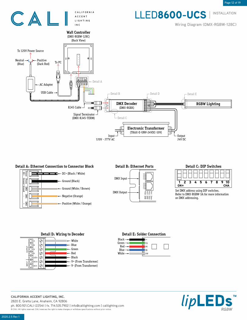
Wiring Diagram (DMX-RGBW-128C)
DMX Decoder(DMX-RGBX)
Electronic Transformer(TRAX-E-UNV-24VDC-10V)
RGBW Lighting
Detail A
Output24V DC
Detail B Detail D Detail E
Detail C
Wall Controller(DMX-RGBW-128C)
(Back View)
Positive(Dark Red)
AC Adapter
Neutral(Blue)
USB Cable
To 120V Power Source
To PC
Input120V - 277V AC
Signal Terminator(DMX-RJ45-TERM)
RJ45 Cable
Ground (White / Brown)
Ground (Black)
DC+ (Black / White)
Negative (Orange)
Positive (White / Orange)
Detail A: Ethernet Connection to Connector Block Detail B: Ethernet Ports
12
34
56
78
12
34
56
78
Pin1 : D
ata+P
in2 : Data-
Pin7 : G
ND
Pin8 : G
ND
DMX Input
DMX Output
Detail C: DIP Switches
Set DMX address using DIP switches.Refer to DMX-RGBW-3A for more informationon DMX addressing.
Detail D: Wiring to Decoder
WhiteBlueGreenRedBlackV+ (From Transformer)V- (From Transformer)
Detail E: Solder ConnectionBlackGreen
RedBlue
White

Page 13 of 19
INSTALLATIONLLED8600-UCS
2020.2.5 Rev 1
CALIFORNIA ACCENT LIGHTING, INC.2820 E. Gretta Lane, Anaheim, CA 92806ph. 800.921.CALI (2254) | fx. 714.535.7902 | [email protected] | calilighting.com© CALI. All rights reserved. CALI reserves the right to make changes or withdraw specifications without prior notice.
lipLEDs™RGBW
Setup of DMX Controller (DMX-RGBW-1024C)
1. Unbox DMX controller components. You will need the DMX controller, power connector, USB cable, and RJ45 ethernet cable.
4. Install Nicolaudie Easy Stand Alone software on your computer. Use software disc or go to https://www.nicolaudie.com/en/esa.htm to download software and software manual.
2. Connect one end of RJ45 cable to the DMX input port on DMX-RGBX. Connect the other end to the DMX output port on the controller (top port). Refer to wiring diagram for details.
8. To connect controller to a network, connect one end of an RJ45 Ethernet cable to the Ethernet port on the controller (bottom port). Connect the other end of the cable to a router or switch. The controller should connect to the network automatically.
9. Confirm the controller is connected to the network by holding the standby button for 3 seconds until menu appears on screen. Use the arrow buttons to toggle through the menu to Ethernet section. Press the middle “stick” button on the controller to select choice. Toggle through the menu until either DHCP Success or DHCP Fail appears. If DHCP Fail appears, the controller is likely being blocked by a firewall.
3. Connect power plug to standard 120V outlet.
6. Mount an electrical box (not included) into the wall where controller will be mounted.
11. Remove back plate from front panel. Slide back plate towards the bottom of the controller to disengage the slide lock, then gently remove back plate from front panel. Route wiring from electrical box through the large hole in the back plate of controller.
7. Insert assembled connector block into the receiving port on the back of controller.
Receiving Port
DMX Output Port
Connector Block
Mounting Screw
Front Panel
5. Connect controller via USB cable to a computer with Nicolaudie software installed, then program scenes into controller as desired. Remove USB cable after programming is complete. Note: Refer to Operating ESA Software for a guide on creating and saving scenes.
10. Download DMX Lightpad 3 or Easy Remote to a mobile device and connect the device to the same network. The app will automatically detect the controller.
RJ45 Ethernet Cable(Ethernet B Connection)
DMX Controller(DMX-RGBW-1024C)
AC Adapter
Connector Block
Power Plug
Receiving Port
DMX Output Port
Connector Block
10. Mount controller interface onto the electrical box. Secure with at least two screws, then snap the front panel onto the back plate. Wait at least 30 seconds for the touch sensitivity to adjust.
Page 14 of 19
INSTALLATIONLLED8600-UCS
2020.2.5 Rev 1
CALIFORNIA ACCENT LIGHTING, INC.2820 E. Gretta Lane, Anaheim, CA 92806ph. 800.921.CALI (2254) | fx. 714.535.7902 | [email protected] | calilighting.com© CALI. All rights reserved. CALI reserves the right to make changes or withdraw specifications without prior notice.
lipLEDs™RGBW
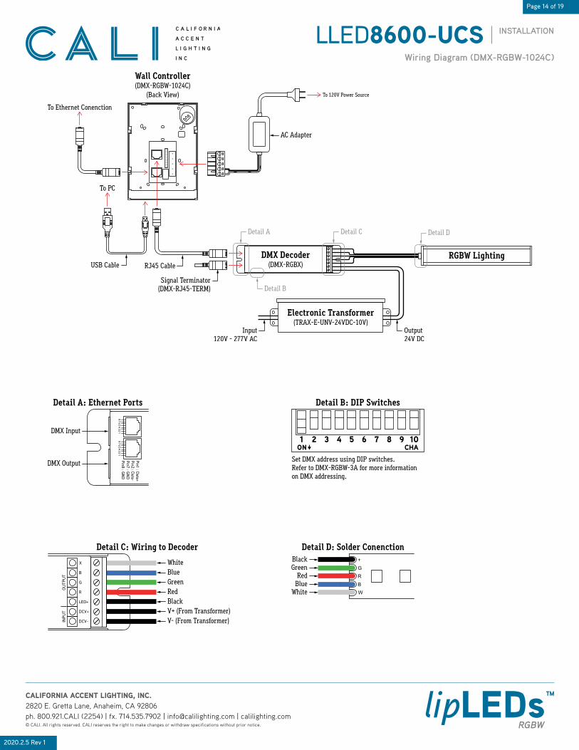
Wiring Diagram (DMX-RGBW-1024C)
DMX Decoder(DMX-RGBX)
Electronic Transformer(TRAX-E-UNV-24VDC-10V)
RGBW Lighting
Output24V DC
Detail A Detail C Detail D
Detail B
Wall Controller(DMX-RGBW-1024C)
(Back View)
AC Adapter
To PC
To Ethernet Conenction
Input120V - 277V AC
Signal Terminator(DMX-RJ45-TERM)
RJ45 CableUSB Cable
To 120V Power Source
Detail A: Ethernet Ports
12
34
56
78
12
34
56
78
Pin1 : D
ata+P
in2 : Data-
Pin7 : G
ND
Pin8 : G
ND
DMX Input
DMX Output
Detail B: DIP Switches
Set DMX address using DIP switches.Refer to DMX-RGBW-3A for more informationon DMX addressing.
Detail C: Wiring to Decoder
WhiteBlueGreenRedBlackV+ (From Transformer)V- (From Transformer)
Detail D: Solder ConenctionBlackGreen
RedBlue
White

Page 15 of 19
INSTALLATIONLLED8600-UCS
2020.2.5 Rev 1
CALIFORNIA ACCENT LIGHTING, INC.2820 E. Gretta Lane, Anaheim, CA 92806ph. 800.921.CALI (2254) | fx. 714.535.7902 | [email protected] | calilighting.com© CALI. All rights reserved. CALI reserves the right to make changes or withdraw specifications without prior notice.
lipLEDs™RGBW
ESA Software Tutorial (1 of 2)
1. Install Nicolaudie Easy Stand Alone software. Use provided software disc or go to https://www.nicolaudie.com/en/esa.htm to download software and software manual.
2. Connect controller via USB cable to a computer with Nicolaudie software installed, then open software. It is recommended to create scenes while controller and lighting are connected to a computer. This provides instantaneous feedback while creating scenes.
3. The program will display a prompt to select your favorite operating mode. Select the STICK2 or STICK3A option and click OK.
4. Set DMX address for each fixture connected to the controller. Set DMX address using DIP switches on the side of decoder. The sum of the value of each engaged DIP switch creates the DMX address. Example: 1 + 4 + 32 = 37. DMX start address for this decoder is 37.
5. If all fixtures will be controlled together, continue to step 6a. If each fixture will be controlled independently, continue to step 6b.
7a. The program will open to a blank show file by default. Patch each fixture to the DMX universe using the previously set DMX addresses. Under the Scan Library menu, in the generic folder, select “rgbw”. This tells the software that a 4 channel RGBW fixture is connected to the controller. The below diagram illustrates how to patch fixture #1. If all fixtures will be controlled together, skip step 7b.
6a. If all fixtures will be controlled together, set the DMX start address of each fixture to 1.
6b. If each fixture will be controlled independently, set the DMX start addresses in sequence. The start address controls the first channel (red) of the RGBW fixture. The second, third, and fourth channels (green, blue, white) will automatically be detected by the software and assigned DMX addresses within the DMX universe, which will be detailed later. Example: Three fixtures with one decoder each. Set the DMX start address of the first fixture to 1. Set the DMX start address of the second fixture to 5. Set the DMX start address of the third fixture to 9, and so on. Refer to the below diagram.
Generic 4 ChannelRGBW Fixture
DMX UniverseLeave as default (1)
Number of fixtureswith this address (1)
Click Patch afterinformation is complete
Generic Folder
First DMX ChannelEnter DMX Address of fixture 1 (1)
Patch Fixture #1(DMX Address: 1)
Scale ESA Images 48%
Wall Controller(DMX-RGBW-128C
or DMX-RGBW-1024C)
DMX Decoder(DMX-RGBX)
Electronic Transformer(TRAX-E-UNV-24VDC-10V)
Fixture #1 (RGBW Lighting)
DMX Decoder(DMX-RGBX)
Electronic Transformer(TRAX-E-UNV-24VDC-10V)
Fixture #2 (RGBW Lighting)
To Power Source
To Power Source
To Power Source
DMX Decoder(DMX-RGBX)
Electronic Transformer(TRAX-E-UNV-24VDC-10V)
Fixture #3 (RGBW Lighting)
DMX Addresses:Channel 1 (Red): 1 (Start Address)Channel 2 (Green): 2Channel 3 (Blue): 3Channel 4 (White): 4
DMX Addresses:Channel 1 (Red): 1 (Start Address)Channel 2 (Green): 2Channel 3 (Blue): 3Channel 4 (White): 4
DMX Addresses:Channel 1 (Red): 1 (Start Address)Channel 2 (Green): 2Channel 3 (Blue): 3Channel 4 (White): 4
Wall Controller(DMX-RGBW-128C
or DMX-RGBW-1024C)
DMX Decoder(DMX-RGBX)
Electronic Transformer(TRAX-E-UNV-24VDC-10V)
Fixture #1 (RGBW Lighting)
DMX Decoder(DMX-RGBX)
Electronic Transformer(TRAX-E-UNV-24VDC-10V)
Fixture #2 (RGBW Lighting)
To Power Source
To Power Source
To Power Source
DMX Decoder(DMX-RGBX)
Electronic Transformer(TRAX-E-UNV-24VDC-10V)
Fixture #3 (RGBW Lighting)
DMX Addresses:Channel 1 (Red): 1 (Start Address)Channel 2 (Green): 2Channel 3 (Blue): 3Channel 4 (White): 4
DMX Addresses:Channel 1 (Red): 5 (Start Address)Channel 2 (Green): 6Channel 3 (Blue): 7Channel 4 (White): 8
DMX Addresses:Channel 1 (Red): 9 (Start Address)Channel 2 (Green): 10Channel 3 (Blue): 11Channel 4 (White): 12 DMX address set to 37.
Switches 1, 3, and 6 are engaged (on).
16 328421 256 T12864
DIP switch value for each switch.Switch 10 is used for termination.Engage Switch 10 on the last decoderof a sequence to terminate signal.

Page 16 of 19
INSTALLATIONLLED8600-UCS
2020.2.5 Rev 1
CALIFORNIA ACCENT LIGHTING, INC.2820 E. Gretta Lane, Anaheim, CA 92806ph. 800.921.CALI (2254) | fx. 714.535.7902 | [email protected] | calilighting.com© CALI. All rights reserved. CALI reserves the right to make changes or withdraw specifications without prior notice.
lipLEDs™RGBW
ESA Software Tutorial (2 of 2)
7b. Patch fixture #2 and fixture #3.
8. To create a custom scene, click on the Editor tab at the top left of the interface. A new, blank scene named New Scene will appear by default.
9. Each scene is made up of a series of steps. Create steps using the Steps menu on the upper right of the interface.
10. Set the color value of each channel for each step. Under the DMX Universe 1 tab, channel 1 - 4 controls the RGBW value of fixture #1. Channel 5 - 8 controls the RGBW value of fixture #2. Channel 9 - 12 controls the RGBW value of fixture #3. Use the slider to set each light level or enter light level in the light level display. Use the arrows at the top and bottom of slider track to fine tune the value. Example: Channel 1 controls fixture #1 red value (65). Channel 6 controls fixture #2 green value (65). Channel 11 controls fixture #3 blue value (65).
11. After setting RGBW values, set fade time and hold time in the Steps menu in the upper right of the interface. Double click 00m00s00 under Fade Time, then use the arrow keys to set desired time in minutes and seconds. Double click 00m00s00 under Hold Time, then use the arrow keys to set desired time. Double click Dimmer to set brightness value. Example: Fade Time: 00m02s00 (2 seconds). Hold Time: 00m04s00 (4 seconds). Dimmer: 100 (100% brightness).
12. Create additional steps as needed by repeating steps 9 - 11. Play your scene and make adjustments to the parameters as desired. When a scene is complete, save as a Show File (.dlm) as a backup on your computer. Create up to 24 scenes using the Editor tab.
13. Save scenes to the DMX Controller by using the Stand Alone tab in the upper left of the interface. Click the write memory button, then click OK. The program will write the scenes into the controller to be used independently from the computer. Note: Writing the memory will erase all factory-programmed scenes from the controller.
Patch Fixture #2(DMX Address: 5)
Patch Fixture #3(DMX Address: 9)
New Scene
Rename Scene
TriggerImport Scene
Play / Stop Fade On / Off
Set LevelsAdd New StepRecord DMX In LevelsCopy Step Dimming Value
Increase Level +1
Slider
Decrease Level -1
Light Level Display
Channel 1: Red
Channel 2: Green
Channel 3: Blue
Channel 4: White
Channel 5: Red
Channel 6: Green
Channel 7: Blue
Channel 8: White
Channel 9: Red
Channel 10: Green
Channel 11: Blue
Channel 12: White
Step NumberFade Time Hold Time Dim Level
Total memory usage.Create up to 2556 steps across 24 scenes.
Uncheck if controller will be usedexclusively while connected to a PC

Page 17 of 19
INSTALLATIONLLED8600-UCS
2020.2.5 Rev 1
CALIFORNIA ACCENT LIGHTING, INC.2820 E. Gretta Lane, Anaheim, CA 92806ph. 800.921.CALI (2254) | fx. 714.535.7902 | [email protected] | calilighting.com© CALI. All rights reserved. CALI reserves the right to make changes or withdraw specifications without prior notice.
lipLEDs™RGBW
Troubleshooting & Continuity Test
1. Turn off power before beginning. Check for any twisting or damage to the circuit in the LED lightstrip. If there is excessive damage and the circuit is broken, the lightstrip must be replaced.
3. Check to make sure cuts in the lightstrip are clean and not frayed, causing positive and negative copper pads to touch.
2. Check for metal particles or other foreign objects causing the short.
TROUBLESHOOTING TIPS• Do not reset the breaker multiple times• If the unit is overloaded, the breaker will trip, shutting off the transformer and lights• If the breaker reset button has been held down by hand or any type of pressure, such as duct tape, or if the breaker has been reset multiple times without troubleshooting, the unit will: - Burn the transformer bobbin - Burn the thermal or magnetic breaker - Burn the primary or secondary wires due to high amperage caused by overload - Short circuit in line which will not allow the breaker to reset - Damage the lighting
1. Turn power off before beginning. Verify power is turned off by using a non-contact circuit tester. Touch the probe of the tester to positive wire of the power source. The tester will light up if an electrical current is detected.
3. Verify that your tester is functional by touching probes together. The tester should light up, beep, or read 0Ω (ohms) of resistance.
4. Touch the red probe to the black wire and the black probe to each colored wire. If a conductive path is formed between the black wire and any other wire, the multimeter will beep, flash, or read 0Ω (ohms). Troubleshoot to identify the malfunction in the line. If there is no conductive path, the multimeter will not show any feedback.
5. Touch the red probe to the fixture extrusion and the black probe to the black wire. If a conductive path is formed between the extrusion and the black wire, the multimeter will beep, flash, or read 0Ω (ohms). Troubleshoot to identify the malfunction in the line. If there is no conductive path, the multimeter will not show any feedback.
6. Touch the red probe to the fixture extrusion and the black probe to the each colored wire. If a conductive path is formed between the extrusion and any colored wire, the multimeter will beep, flash, or read 0Ω (ohms). Troubleshoot to identify the malfunction in the line. If there is no conductive path, the multimeter will not show any feedback.
7. Set voltmeter to DC voltage and test power source. Confirm the correct voltage before connecting lighting to power source. If voltage reading is more than 1 volt higher than the marked output voltage, there is a problem with the power source or driver.
8. Connect power connector to power source. If LEDs do not turn on, flip polarity (+ -) or power source connection to power connector.
CONTINUITY TESTA continuity test is performed to determine if electricity can pass through two points on an electrical circuit. This helps identify shorts or malfunctions in the line or fixture. Use a multimeter or continuity tester to perform the steps below. • Always perform a continuity test before connecting lighting to power source. • Malfunctions are not always as obvious as the lights not turning on. • A short or malfunction in the line or fixture will cause damage over time, ultimately damaging the lighting and voiding warranty.
Black
Black Probe
Red Probe
RGBW Lighting
BlackBlack Probe
RGBW Lighting
Red Probe
Black Probe RGBW Lighting
Red Probe
2. Setup your tester. First insert the black probe lead into the COM jack, then insert the red probe lead into the VΩ jack.
12
VAC
(-)
(+)
Black Probe
Red Probe
Damaged LightstripTorn Lightstrip
Metal FlakesForeign Object
Frayed End

Page 18 of 19
INSTALLATIONLLED8600-UCS
2020.2.5 Rev 1
CALIFORNIA ACCENT LIGHTING, INC.2820 E. Gretta Lane, Anaheim, CA 92806ph. 800.921.CALI (2254) | fx. 714.535.7902 | [email protected] | calilighting.com© CALI. All rights reserved. CALI reserves the right to make changes or withdraw specifications without prior notice.
lipLEDs™RGBW
Electronic Transformer Remote Driver (TRA-E)
WATTS (VA) PER CIRCUIT (Maximum wire length to prevent voltage drop)
WIRESIZE VOLTAGE 16
VA25VA
40VA
60VA
80VA
90VA
96VA
120VA
150VA
185VA
240VA
320VA
14GA 12V 46’ 42’ 37’ 32’ 28’ 25’ 23’ 21’ 18’ 16’ 11’ 4’
14GA 24V 93’ 84’ 75’ 66’ 56’ 51’ 47’ 42’ 37’ 33’ 23’ 9’
12GA 12V 74’ 66’ 59’ 52’ 44’ 40’ 37’ 33’ 29’ 26’ 18’ 7’
12GA 24V 147’ 132’ 118’ 103’ 89’ 81’ 74’ 67’ 59’ 52’ 37’ 15’
10GA 12V 117’ 106’ 94’ 82’ 71’ 65’ 59’ 53’ 47’ 41’ 30’ 12’
10GA 24V 235’ 211’ 188’ 165’ 141’ 129’ 118’ 106’ 94’ 83’ 59’ 24’
8GA 12V 186’ 168’ 149’ 130’ 112’ 102’ 93’ 84’ 74’ 65’ 46’ 18’
8GA 24V 374’ 336’ 299’ 262’ 224’ 205’ 187’ 168’ 149’ 131’ 93’ 37’
PREVENTING VOLTAGE DROPThe maximum wire length to prevent voltage drop refers to the wire that is used between the transformer and 1st LED of the lighting fixture. If the gauge wire is too small, the fixture will not receive correct voltage.
Example: LED luminaire requires 24VDC to operate effectively. If the wire gauge is too small to carry the 24VDC current from the transformer, the voltage can shrink to 16VDC, which is insufficient to power the lighting.
MAXIMUM RUN BASED ON 80% LOAD OF ELECTRONIC TRANSFORMER (TRA-E) MAXIMUM WATTAGE
TRANSFORMERWATTAGE 80% LOAD 1.5W
MAX RUN2W
MAX RUN2.5W
MAX RUN3.6W
MAX RUN4W
MAX RUN4.5W
MAX RUN5W
MAX RUN5.5W
MAX RUN6W
MAX RUN6.5W
MAX RUN
16 12.8W 8.5’ 6.4’ 5.1’ 3.5’ 3.2’ 2.8’ 2.5’ 2.3’ 2.1’ 1.9’
25 20W 13.3’ 10’ 8’ 5.5’ 5’ 4.4’ 4’ 3.6’ 3.3’ 3.1’
40 32W 21.3’ 16’ 12.8’ 8.8’ 8’ 7.1’ 6.4’ 5.8’ 5.3’ 4.9’
60 48W 32’ 24’ 19.2’ 13.3’ 12’ 10.6’ 9.6’ 8.7’ 8’ 7.3’
80 64W 42.6’ 32’ 25.6’ 17.7’ 16’ 14.2’ 12.8’ 11.6’ 10.6’ 9.8’
90 72W 48’ 36’ 28.8’ 20’ 18’ 16’ 14.4’ 13.1’ 12’ 11.1’
96 76.8W 51.2’ 38.4’ 30.7’ 21.3’ 19.2’ 17.1’ 15.36’ 13.9’ 12.8’ 11.8’
120 96W 64’ 48’ 38.4’ 26.6’ 24’ 21.3’ 19.2’ 17.4’ 16’ 14.7’
150 120W 80’ 60’ 48’ 33.3’ 30’ 26.6’ 24’ 21.8’ 20’ 18.4’
185 148W 98.6’ 74’ 59.2’ 41.1’ 37’ 32.8’ 29.6’ 26.9’ 24.6’ 22.7’
240 192W 128’ 96’ 76.8’ 53.3’ 48’ 42.6’ 38.4’ 34.9’ 32’ 29.5’
320 256W 170.6’ 128’ 102.4’ 85.3’ 64’ 56.8’ 51.2’ 46.5’ 42.6’ 39.3’
TRANSFORMER CARE• Do not submerge transformers in any liquid• Do not leave any exposed wires• Do not cover transformer without proper ventilation• Do not install damaged transformer• Do not exceed maximum load
MOUNTING INSIDE AN ENCLOSURE• Only mount drivers inside enclosures rated for your application• Always ground drivers to enclosure• Do not mount drivers without an enclosure• Use enclosure knockouts and water-tight cordgrips when applicable
DIMMER TRIM VALUES• Set dimmer trim value as needed to prevent flickering and irregular dimming• Note: Review dimmer specs for trim value adjustment
LED LightingTRA
Distance from transformerto first LED of lighting
Minimum Light Level(Low-End) Trim
Front
Maximum Light Level(High-End) Trim
Side
Maximum Light Level(High-End) Trim
Bottom

Page 19 of 19
INSTALLATIONLLED8600-UCS
2020.2.5 Rev 1
CALIFORNIA ACCENT LIGHTING, INC.2820 E. Gretta Lane, Anaheim, CA 92806ph. 800.921.CALI (2254) | fx. 714.535.7902 | [email protected] | calilighting.com© CALI. All rights reserved. CALI reserves the right to make changes or withdraw specifications without prior notice.
lipLEDs™RGBW
Surge Protector
1.0” 1.52”
.26”
.26”
.25”ø 1.14”.41”
2.91”
1.91”
1.16”
.09”
.58”
0-10V DimmingALS-SP
TRA-E Power Source120V-277V
Hot Ground (Green)
V+Neutral
Hot (Black)
V-
Neutral (White)
Ground (Green)
V+
DMX Decoder(DMX-RGBX)
RGBW Lighting
V-
SURGE PROTECTOR SPECIFICATIONS
MODEL INPUT VOLTAGE SURGE PROTECTION LEVEL MOUNTING ENCLOSURE MATERIAL INPUT LEADS INPUT FREQUENCY
ALS-SP 120V - 277V 10kV, 10kA, ANSI C62.41 Category C SnapLOCK / Footed Polycarbonate 6”, 18AWG stranded, 105°C stripped, 3/8” tinned 60Hz
PRODUCT FEATURESThe Surge Series are 3-leaded devices that protect Line-Ground, Line-Neutral, and Neutral-Ground in accordance with IEEE / ANSI C62.41.2 guidelines. Protects against surges according to IE EE C62.41.2 C High (10kA and 10kV). Surge current rating = 10,000 Amps using industry standard 8/20 µSec wave. Surge Location Rated Category C3. UL Recognized Component in the United States and Canada (UL1449). Type 4 Surge Protection Device. High temperature, flame retardant plastic enclosure, 85°C maximum surface temperature rating. Thermally Protected Transient Over-voltage Circuit.
PRODUCT SPECIFICATIONSThe Surge series of products are designed to be used in conjunction with LED Drivers and fixtures to provide an additional level of protection against powerline disturbances in industrial, commercial and residential applications where surge protection to IEEE C62.41.2 is required.
WIRING DIAGRAM
CASE DIMENSIONS
Note: Wire colors vary based on model. See individual TRA-E submittal for more information, or refer to wire callouts on transformer labeling. Always confirm wire colors before connecting to power source.