outdoor decorative gas fireplace - lib.store.yahoo.net · an lp-cylinder not connected for use...
TRANSCRIPT
ULRC
LISTED
US
This is a Single-Sided fireplace with the option of converting it into a See-Through fireplace
P900861-00
- Do not store or use gasoline or other flammable vapors and liquids in the vicinity of this or any other appliance.
- WHAT TO DO IF YOU SMELL GAS• Do not try to light any appliance. • Do not touch any electrical switch; do not use
any phone in your building. • Leave the building immediately.• Immediately call your gas supplier from a neigh-
bor’s phone. Follow the gas supplier’s instruc-tions.
• If you cannot reach your gas supplier, call the fire department.
- Installation and service must be performed by a qualified installer, service agency or the gas supplier.
WARNING:
FIRE OR EXPLOSION HAZARDFailure to follow safety warnings exactly could result in serious injury, death, or property damage.
AVERTISSEMENT:
RISQUED’INDENDIE OU D’EXPLOSIONLe non-respect Des avertissements de sécurité pourrait d’entraîner des blessures graves, la mort ou des dom-mages matériels.
- Ne pas entreposer ni utilizer d’essence ni d’autres vapeurs ou liquides inflammables dans le voisinage de cet appareil ou de tout autre appareil.
- QUE FAIRE SI VOUS SENTEZ UNE ODEUR DE GAZ:
• Ne pas tenter d’allumer d’appareil.• Ne touchez à aucan interrupteur. Ne pas vous servir des
téléphones se trouvant dans le bâtiment où vous trouvez. • Sortez immédiatement de bâtiment.• Appelez immédiatement votre fournisseur de gaz depuis
un voisin. Suivez les instructions du fournisseur. • Si vous ne pouvez rejoindre le fournisseur de gaz, appelez
le service des incindies. - L’installation et l’entretien doivent être assurés par un
installateur ou un service d’entretien qualifié ou par le fournisseur de gaz.
WHEN USED AS AN OUTDOOR APPLIANCE
DANGER CARBON MONOXIDE WARNING• This appliance can produce
carbon monoxide which has no odor.
• Using it in an enclosed space can kill you.
• Never use this appliance in an enclosed space such as a camper, tent, car or home.
WARNING: For Outdoor Use Only.
DANGERIF YOU SMELL GAS:1. Shut off gas to appliance.2. Extinguish any open flame.3. If odor continues, keep away from the appliance and
immediately call your gas supplier or fire depart-ment.
WARNING: Do not store gasoline or other flammable vapors and liquids in the vicinity of this or any other appli-ance. An LP-cylinder not connected for use shall not be stored in the vicinity of this or any other appliance.
WARNING: Improper installation, adjustment, alteration, service or maintenance can cause injury or property damage. Read the installation, operating and maintenance instructions thoroughly before installing or servicing this equipment.
INSTALLER: Leave this manual with the appliance.CONSUMER: Retain this manual for future reference.
Installateur : Laissez cette notice avec l’appareil.Consommateur : Conservez cette notice pour consultation ultérieure.
Installation and Operation Instructions
P/N 900861-00 REV. NC 10/2017
Report No. MH# 60069
Ce manuel est disponible en francais, simplement en faire la demande. Numéro de la pièce 900861-01.
OUTDOOR DECORATIVE GAS FIREPLACE
Models
BarcelonaLights36ZEN
VRE4636ZEN
BarcelonaLights48ZEN
VRE4648ZEN
BarcelonaLights60ZENVRE4660ZEN
BarcelonaLights72ZENVRE4672ZEN
INSTALLATION PRECAUTION: This fireplace requires a minimum 18-square inches (per side) of cross ventilation. Failure to provide proper ventilation can void the warranty.
IHP.us.com 900861-00NC2
Safety ........................................................................................ 2-3Local Codes ................................................................................. 3Installation Precautions ........................................................... 4-6 Gas Line and Cross Ventilation Requirements ......................... 5 Hard piping and High Elevation ................................................ 6Fireplace Specifications .............................................................. 7Single-Sided Fireplace Application ........................................ 8-10 Dimensions; Combustible Clearances; Mantel Clearances ........ 9 Framing with Metal Studs ....................................................... 10See-Through Fireplace Application ...................................... 11-14 Converting Fireplace to a See-Through Model ........................ 12 Dimensions; Combustible Clearances; Mantel Clearances ...... 13 Framing with Metal Studs ....................................................... 14LED Lighting Installation ...................................................... 15-22Wiring Diagrams ................................................................... 20-22Final Preparation .................................................................. 23-27 Installing Pilot Covers in Burner Pan ....................................... 23 Installation of Media in Burner Pan/Trough ............................. 24 Windshield Location and Pilot Operation ................................ 25 Installation of Hoods and Windshield ...................................... 26 Flame Height ........................................................................... 27Operation .................................................................................... 28 Lighting Instructions ............................................................... 28 Product Reference Information ............................................... 28Fireplace Maintenance .............................................................. 29Troubleshooting .................................................................... 30-31Optional Accessories ................................................................ 31Gas Conversion Instructions ................................................. 32-35Replacement Parts ................................................................ 36-38Warranty .................................................................................... 39
This fireplace ships from the factory as a single-sided fireplace with the option of removing the back panels to convert it into a see-through fireplace. Your spe-cific application, single-sided or see-through will determine how you install and frame this fireplace. Carefully read through this manual to understand.
DESCRIPTION: These Outdoor fireplace models come ready to op-erate with HI/LO capabilities once installation is complete. They use an electronic ignition that runs off a 7.5VDC adaptor. In addition, each fireplace is equipped with LED lighting as a standard feature. Each model can operate the LED lights with or without the fireplace operating. The LED lights run off of a 12-volt DCV adaptor.
These are radiant fireplaces only and do not have a fan option. Do not burn real wood or other combustible materials in these fireplaces. Use only approved media. All models are shipped as
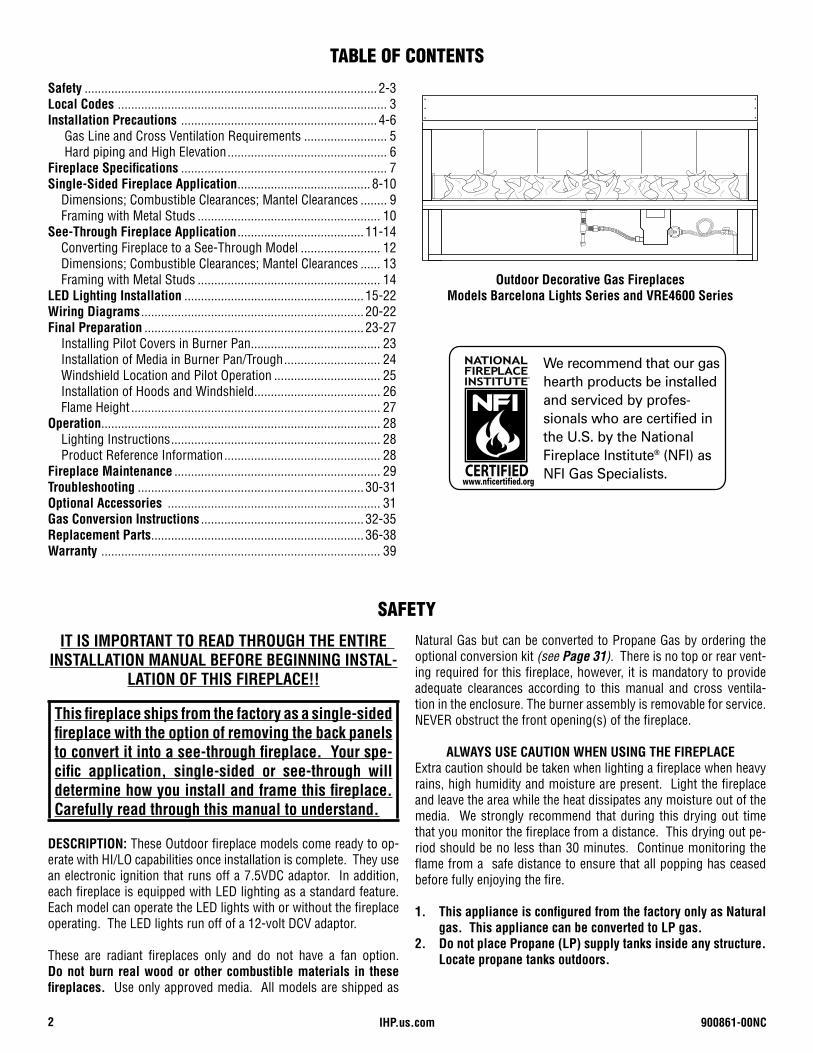
Outdoor Decorative Gas FireplacesModels Barcelona Lights Series and VRE4600 Series
TABLE OF CONTENTS
SAFETYNatural Gas but can be converted to Propane Gas by ordering the optional conversion kit (see Page 31). There is no top or rear vent-ing required for this fireplace, however, it is mandatory to provide adequate clearances according to this manual and cross ventila-tion in the enclosure. The burner assembly is removable for service. NEVER obstruct the front opening(s) of the fireplace.
ALWAYS USE CAUTION WHEN USING THE FIREPLACE Extra caution should be taken when lighting a fireplace when heavy rains, high humidity and moisture are present. Light the fireplace and leave the area while the heat dissipates any moisture out of the media. We strongly recommend that during this drying out time that you monitor the fireplace from a distance. This drying out pe-riod should be no less than 30 minutes. Continue monitoring the flame from a safe distance to ensure that all popping has ceased before fully enjoying the fire.
1. This appliance is configured from the factory only as Natural gas. This appliance can be converted to LP gas.
2. Do not place Propane (LP) supply tanks inside any structure. Locate propane tanks outdoors.
IT IS IMPORTANT TO READ THROUGH THE ENTIRE INSTALLATION MANUAL BEFORE BEGINNING INSTAL-
LATION OF THIS FIREPLACE!!
900861-00NC 3IHP.us.com
WARNING• Do not leave unattended during use.• Do not use for cooking.• Follow all gas leak procedures in this manual prior to operation.
WARNINGFuels used in gas fired appliances, and the products of combus-tion such as fuels, contain chemicals known to cause cancer, birth defects and/or other reproductive harm. This warning is issued pursuant to the California Health and Safety Code Sec. 25249.1.
WARNING PROPANE TANKS ARE AT PRESSURES THAT WILL CAUSE DAMAGE TO VALVE COMPONENTS. VERIFY THAT THE TANKS HAVE STEP DOWN REGULATORS TO REDUCE THE PRESSURE TO SAFE LEVELS.
Install and use fireplace with care. Follow all local codes. In the ab-sence of local codes, use the National Fuel Gas Code, ANSI Z223.1/ NFPA 54 (USA) - latest edition. Available from:
American National Standards Institute, Inc.25 West 43rd Street, 4th floor
New York, NY 10036
National Fire Protection Association, Inc.1 Batterymarch Park
Quincy, MA 02169-7471
CODES AND STANDARDSThese fireplaces comply with National Safety Standards and are test-ed and listed by Underwriters Laboratories (Report No. MH#60069) to ANSI Z21.97, CSA 2.41 in both USA and Canada, as outdoor dec-orative gas appliances. The installation must conform to local codes or, in the absence of local codes, with the National Fuel Gas Code, ANSI Z223.1/ NFPA 54 (USA) - latest edition or CAN/CGA-B149.1 Natural gas and propane installation code (Canada) - latest edition.
AN OUTDOOR SPACE IS DEFINED AS FOLLOWS PER ANSI Z21.97:
Outdoor spaces - An appliance is considered to be outdoors if installed with shelter no more inclusive than:(a) With walls on all sides, but with no over-head cover;
3. This fireplace is to be used only outdoors in a well ventilated space and shall not be used in a building, garage, or any other enclosed area.
4. Do not use this fireplace as a wood burning fireplace. Use only high temperature media approved for use with this fire-place.
5. Do not use this fireplace to cook or burn paper or other ob-jects.
6. Do not use if exposed to or under water. Immediately call a qualified service technician to inspect the fireplace and replace any part of the control system and any gas control which has been under water.
7. Turn fireplace OFF and let cool before servicing. Only a qual-ified service person should perform service.
8. To prevent performance problems in Propane (LP) fireplaces, do not use a Propane tank less than 100lbs. capacity.
SAFETYContinued
LOCAL CODES(b) Within a partial enclosure which includes an overhead cover and no
more than two side walls. These side walls may be parallel, as in a breezeway, or at right angles to each other; or
(c) Within a partial enclosure which includes an overhead cover and three sidewalls, as long as 30% or more of the horizontal periphery of the enclosure is permanently open.
Massachusetts Requirements These appliances are approved for installation in the US state of Mas-sachusetts if the following additional requirements are met:• Un-vented Room Heaters shall be installed in accordance with 527
CMR 30.• Installation and repair must be done by a plumber or gas fitter li-
censed in the Commonwealth of Massachusetts.• The flexible gas line connector used shall not exceed 36 inches (92
centimeters) in length.• The individual manual shut-off must be a T-handle type valve.• Unvented appliances may NOT be installed in bedrooms or bath-
rooms.• A working smoke detector must be installed in the area where vent-
free appliances are installed.Seller of unvented propane or natural gas-fired supplemental room heaters shall provide to each purchaser a copy of 527 CMR 30 upon sale of the unit.
IHP.us.com 900861-00NC4
1. These fireplaces are designed for outdoor use only. Not ap-proved for any indoor use.
2. We recommend using 3/4” black iron pipe; however please re-fer to the National Fuel Gas Code, ANSI Z223.1/ NFPA 54 (USA) - latest edition or CAN/CGA-B149.1 Natural Gas And Propane Installation Code (Canada) - latest edition for proper pipe sizing when exceeding 20-feet in length for fireplaces .
3. Determine which fireplace you are preparing to install, single-sided or see-through (refer to Page 8 or 11).
4. This fireplace is not a “load bearing” fireplace. All finishing materials must be supported by the surrounding structure and not rely on the fireplace itself.
5. Follow the local code requirements for the gas type being used. This fireplace should be installed in accordance with local codes and ordinances or in the absence of local codes, with the National Fuel Gas Code, ANSI Z223.1/ NFPA 54 (USA) - latest edition or CAN/CGA-B149.1 Natural Gas And Propane Installa-tion Code (Canada) - latest edition.
6. Fireplaces create high temperatures, it is very important to have any combustibles at a safe distance.
7. Fireplace should never be left unattended while in operation. It should always be a safe distance from all trees and combus-tible landscape materials.
8. The fireplace must be installed on a flat, level, stable, non-com-bustible surface. Exception: It is permissible to place one layer of 1/2” cement board underneath the entire fireplace, then it may sit on a flat, level, stable, combustible surface. Drainage is critical to ensure that water does not damage gas valve and components. Never install the fireplace system below grade.
9. CAUTION: A minimum of 18 square inches of cross ventilation (per side) is required to keep the inside of the enclosure dry. Install the supplied VENT-KIT-6x12 (cat. no. F3535) approxi-mately 3 to 4 inches from the floor centered on each end of the fireplace (See Figure 3, Page 5).
10. Never fill the cavity under and around the valve box with any material, this is air space necessary for ventilation.
11. Only non-combustible materials (i.e. metal studs and cement board) should come in direct contact with any part of the fire-place. Underneath area should be non-combustible or a flat level combustible surface according to the clearances specified in this manual. Bend out nailing flanges on ends of fireplace and secure to metal studs.
12. This fireplace is designed to have glass media covering the burner trough, so the burner tube is not visible. Use only the media provided with the appliance or listed in the accessory section of this manual (Page 31). DO NOT COVER THE IGNI-TION HOOD WITH THE GLASS MEDIA. See Figures 33 and 34 on Pages 24 and 25 for details.
13. Gas lines and fittings must be installed in to the non-combus-tible structure. All gas connections must be leak tested before installation of the fireplace. Leak detection is required before regular use of the fireplace.
14. Do not use alternative media that will absorb moisture over time and will not release this moisture quickly. Moisture can boil in this media and can rapidly break apart and cause prop-erty damage or personal injury.
15. Never leave any other combustible material on top of the fire-place. This could cause unsafe operation of this system and damage to the component that will not be covered under our warranty.
16. It is recommended to wear gloves when moving the fireplace into position and watch for sharp edges when handling the fire-place.
WARNING These fireplaces are gas fireplaces. Do not burn wood or other material in these appliances.
WARNING These appliances are not designed or intended to be used for cooking. Do not barbecue, heat food, or roast marshmallows in this appliance. Doing so could damage the appliance and cause injury.
INSTALLATION PRECAUTION: This fireplace requires a minimum 18-square inches (per side) of cross ventilation. Failure to provide prop-er ventilation can void the warranty.
INSTALLATION PRECAUTIONS
900861-00NC 5IHP.us.com
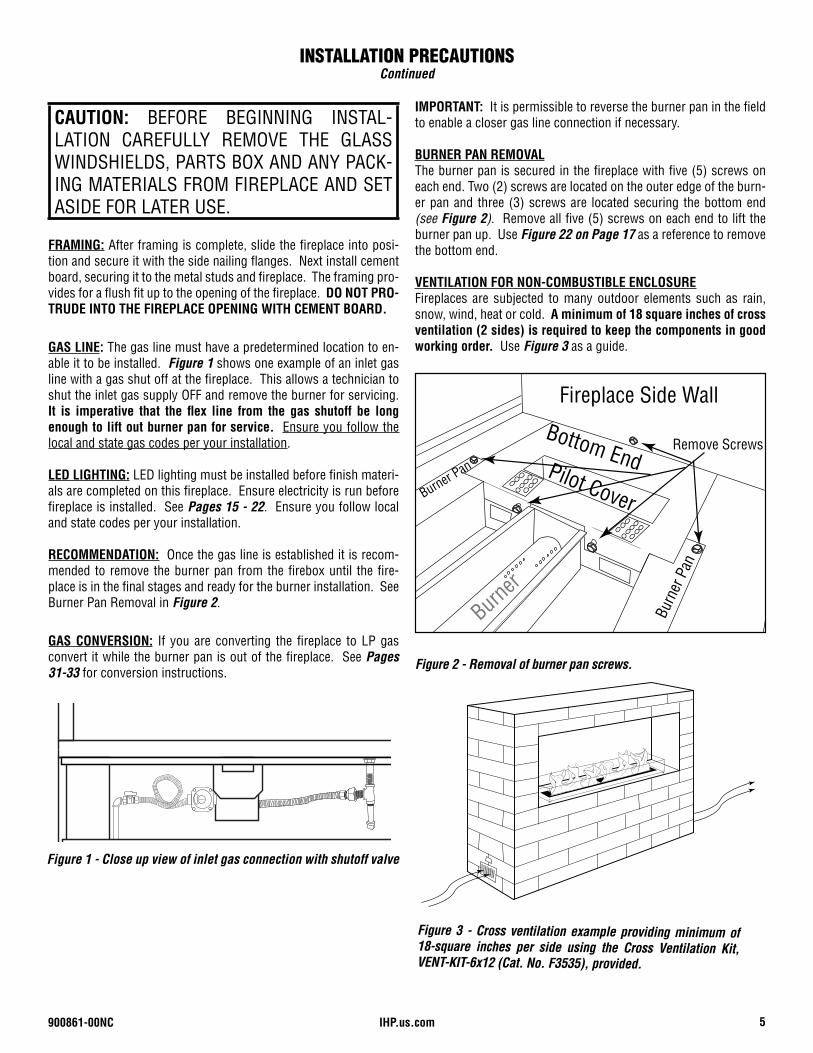
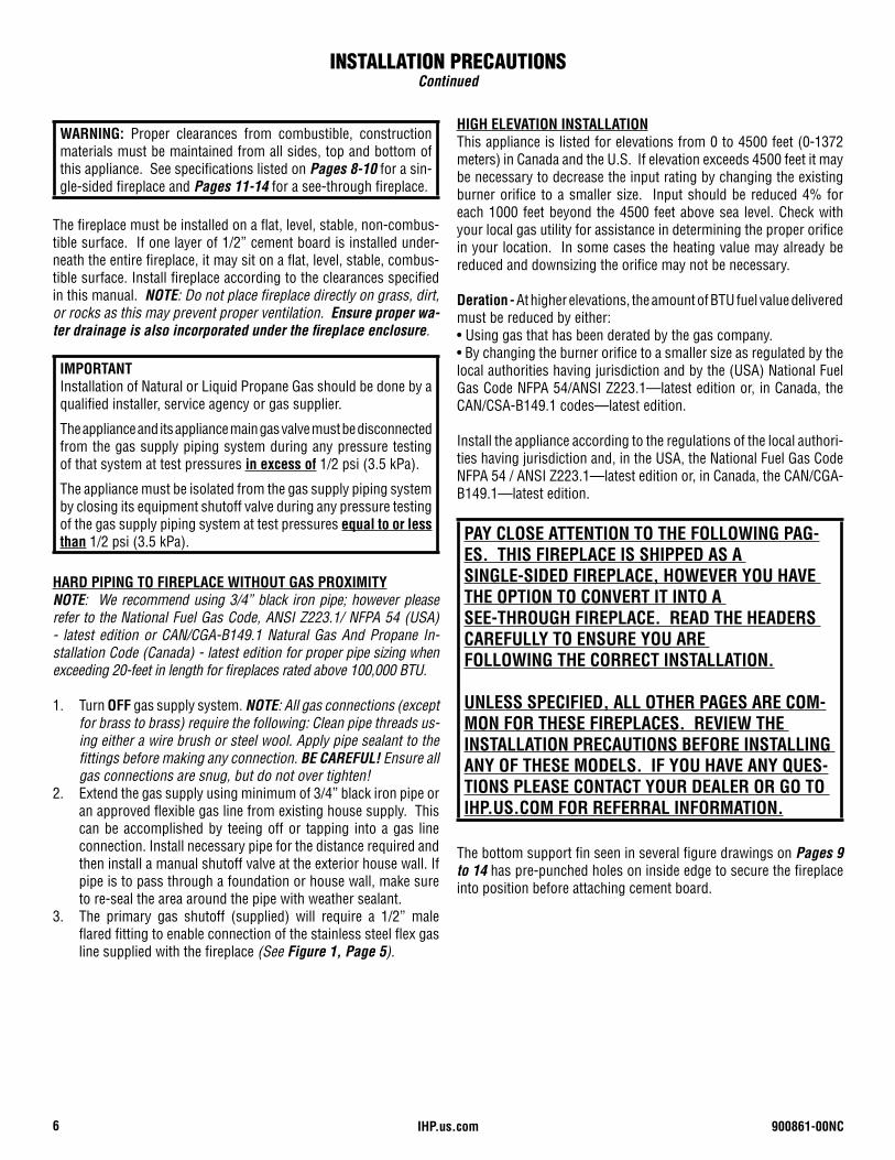
IMPORTANT: It is permissible to reverse the burner pan in the field to enable a closer gas line connection if necessary.
BURNER PAN REMOVALThe burner pan is secured in the fireplace with five (5) screws on each end. Two (2) screws are located on the outer edge of the burn-er pan and three (3) screws are located securing the bottom end (see Figure 2). Remove all five (5) screws on each end to lift the burner pan up. Use Figure 22 on Page 17 as a reference to remove the bottom end.
VENTILATION FOR NON-COMBUSTIBLE ENCLOSUREFireplaces are subjected to many outdoor elements such as rain, snow, wind, heat or cold. A minimum of 18 square inches of cross ventilation (2 sides) is required to keep the components in good working order. Use Figure 3 as a guide.
Figure 1 - Close up view of inlet gas connection with shutoff valve
Figure 3 - Cross ventilation example providing minimum of 18-square inches per side using the Cross Ventilation Kit, VENT-KIT-6x12 (Cat. No. F3535), provided.
FRAMING: After framing is complete, slide the fireplace into posi-tion and secure it with the side nailing flanges. Next install cement board, securing it to the metal studs and fireplace. The framing pro-vides for a flush fit up to the opening of the fireplace. DO NOT PRO-TRUDE INTO THE FIREPLACE OPENING WITH CEMENT BOARD.
GAS LINE: The gas line must have a predetermined location to en-able it to be installed. Figure 1 shows one example of an inlet gas line with a gas shut off at the fireplace. This allows a technician to shut the inlet gas supply OFF and remove the burner for servicing. It is imperative that the flex line from the gas shutoff be long enough to lift out burner pan for service. Ensure you follow the local and state gas codes per your installation.
LED LIGHTING: LED lighting must be installed before finish materi-als are completed on this fireplace. Ensure electricity is run before fireplace is installed. See Pages 15 - 22. Ensure you follow local and state codes per your installation.
RECOMMENDATION: Once the gas line is established it is recom-mended to remove the burner pan from the firebox until the fire-place is in the final stages and ready for the burner installation. See Burner Pan Removal in Figure 2.
GAS CONVERSION: If you are converting the fireplace to LP gas convert it while the burner pan is out of the fireplace. See Pages 31-33 for conversion instructions.
Figure 2 - Removal of burner pan screws.
CAUTION: BEFORE BEGINNING INSTAL-LATION CAREFULLY REMOVE THE GLASS WINDSHIELDS, PARTS BOX AND ANY PACK-ING MATERIALS FROM FIREPLACE AND SET ASIDE FOR LATER USE.
INSTALLATION PRECAUTIONSContinued
Burner
Fireplace Side Wall
Remove Screws
Burn
er P
an
Bottom EndBurner Pan Pilot Cover
IHP.us.com 900861-00NC6
WARNING: Proper clearances from combustible, construction materials must be maintained from all sides, top and bottom of this appliance. See specifications listed on Pages 8-10 for a sin-gle-sided fireplace and Pages 11-14 for a see-through fireplace.
IMPORTANTInstallation of Natural or Liquid Propane Gas should be done by a qualified installer, service agency or gas supplier.
The appliance and its appliance main gas valve must be disconnected from the gas supply piping system during any pressure testing of that system at test pressures in excess of 1/2 psi (3.5 kPa).
The appliance must be isolated from the gas supply piping system by closing its equipment shutoff valve during any pressure testing of the gas supply piping system at test pressures equal to or less than 1/2 psi (3.5 kPa). PAY CLOSE ATTENTION TO THE FOLLOWING PAG-
ES. THIS FIREPLACE IS SHIPPED AS A SINGLE-SIDED FIREPLACE, HOWEVER YOU HAVE THE OPTION TO CONVERT IT INTO A SEE-THROUGH FIREPLACE. READ THE HEADERS CAREFULLY TO ENSURE YOU ARE FOLLOWING THE CORRECT INSTALLATION.
UNLESS SPECIFIED, ALL OTHER PAGES ARE COM-MON FOR THESE FIREPLACES. REVIEW THE INSTALLATION PRECAUTIONS BEFORE INSTALLING ANY OF THESE MODELS. IF YOU HAVE ANY QUES-TIONS PLEASE CONTACT YOUR DEALER OR GO TO IHP.US.COM FOR REFERRAL INFORMATION.
The fireplace must be installed on a flat, level, stable, non-combus-tible surface. If one layer of 1/2” cement board is installed under-neath the entire fireplace, it may sit on a flat, level, stable, combus-tible surface. Install fireplace according to the clearances specified in this manual. NOTE: Do not place fireplace directly on grass, dirt, or rocks as this may prevent proper ventilation. Ensure proper wa-ter drainage is also incorporated under the fireplace enclosure.
HARD PIPING TO FIREPLACE WITHOUT GAS PROXIMITYNOTE: We recommend using 3/4” black iron pipe; however please refer to the National Fuel Gas Code, ANSI Z223.1/ NFPA 54 (USA) - latest edition or CAN/CGA-B149.1 Natural Gas And Propane In-stallation Code (Canada) - latest edition for proper pipe sizing when exceeding 20-feet in length for fireplaces rated above 100,000 BTU.
1. Turn OFF gas supply system. NOTE: All gas connections (except for brass to brass) require the following: Clean pipe threads us-ing either a wire brush or steel wool. Apply pipe sealant to the fittings before making any connection. BE CAREFUL! Ensure all gas connections are snug, but do not over tighten!
2. Extend the gas supply using minimum of 3/4” black iron pipe or an approved flexible gas line from existing house supply. This can be accomplished by teeing off or tapping into a gas line connection. Install necessary pipe for the distance required and then install a manual shutoff valve at the exterior house wall. If pipe is to pass through a foundation or house wall, make sure to re-seal the area around the pipe with weather sealant.
3. The primary gas shutoff (supplied) will require a 1/2” male flared fitting to enable connection of the stainless steel flex gas line supplied with the fireplace (See Figure 1, Page 5).
The bottom support fin seen in several figure drawings on Pages 9 to 14 has pre-punched holes on inside edge to secure the fireplace into position before attaching cement board.
HIGH ELEVATION INSTALLATIONThis appliance is listed for elevations from 0 to 4500 feet (0-1372 meters) in Canada and the U.S. If elevation exceeds 4500 feet it may be necessary to decrease the input rating by changing the existing burner orifice to a smaller size. Input should be reduced 4% for each 1000 feet beyond the 4500 feet above sea level. Check with your local gas utility for assistance in determining the proper orifice in your location. In some cases the heating value may already be reduced and downsizing the orifice may not be necessary.
Deration - At higher elevations, the amount of BTU fuel value delivered must be reduced by either:• Using gas that has been derated by the gas company.• By changing the burner orifice to a smaller size as regulated by the local authorities having jurisdiction and by the (USA) National Fuel Gas Code NFPA 54/ANSI Z223.1—latest edition or, in Canada, the CAN/CSA-B149.1 codes—latest edition.
Install the appliance according to the regulations of the local authori-ties having jurisdiction and, in the USA, the National Fuel Gas Code NFPA 54 / ANSI Z223.1—latest edition or, in Canada, the CAN/CGA-B149.1—latest edition.
INSTALLATION PRECAUTIONSContinued
900861-00NC 7IHP.us.com
FRAMING FIREPLACE
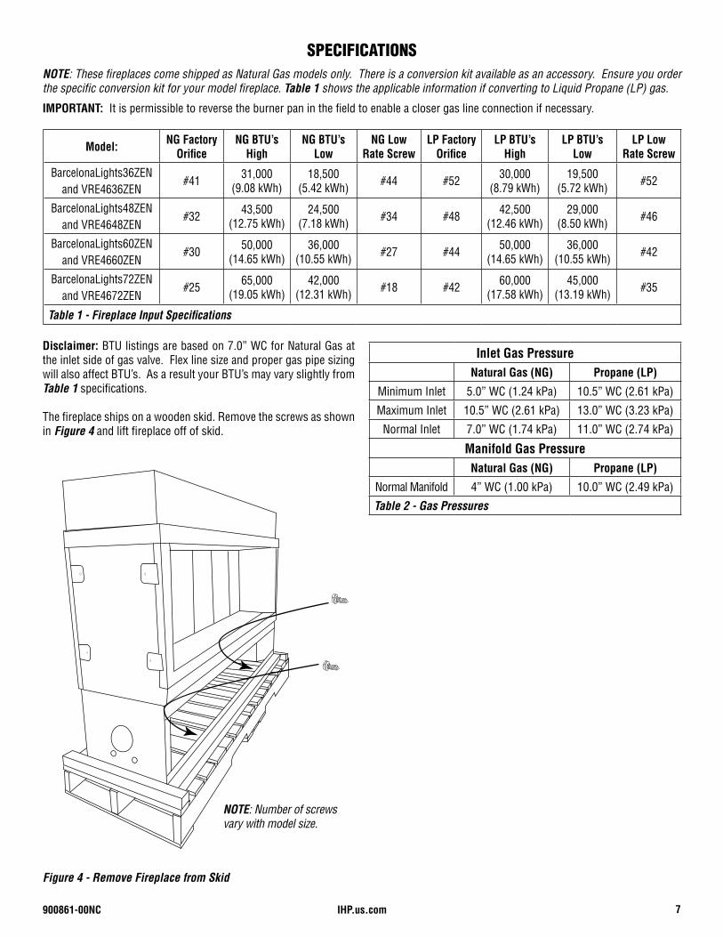
Disclaimer: BTU listings are based on 7.0” WC for Natural Gas at the inlet side of gas valve. Flex line size and proper gas pipe sizing will also affect BTU’s. As a result your BTU’s may vary slightly from Table 1 specifications.
The fireplace ships on a wooden skid. Remove the screws as shown in Figure 4 and lift fireplace off of skid.
NOTE: These fireplaces come shipped as Natural Gas models only. There is a conversion kit available as an accessory. Ensure you order the specific conversion kit for your model fireplace. Table 1 shows the applicable information if converting to Liquid Propane (LP) gas.
IMPORTANT: It is permissible to reverse the burner pan in the field to enable a closer gas line connection if necessary.
Figure 4 - Remove Fireplace from Skid
SPECIFICATIONS
Inlet Gas PressureNatural Gas (NG) Propane (LP)
Minimum Inlet 5.0” WC (1.24 kPa) 10.5” WC (2.61 kPa)
Maximum Inlet 10.5” WC (2.61 kPa) 13.0” WC (3.23 kPa)
Normal Inlet 7.0” WC (1.74 kPa) 11.0” WC (2.74 kPa)
Manifold Gas PressureNatural Gas (NG) Propane (LP)
Normal Manifold 4” WC (1.00 kPa) 10.0” WC (2.49 kPa)
Table 2 - Gas Pressures
Model: NG Factory Orifice
NG BTU’s High
NG BTU’s Low
NG Low Rate Screw
LP FactoryOrifice
LP BTU’s High
LP BTU’s Low
LP Low Rate Screw
BarcelonaLights36ZENand VRE4636ZEN
#41 31,000(9.08 kWh)
18,500(5.42 kWh) #44 #52 30,000
(8.79 kWh)19,500
(5.72 kWh) #52
BarcelonaLights48ZENand VRE4648ZEN
#32 43,500(12.75 kWh)
24,500(7.18 kWh) #34 #48 42,500
(12.46 kWh)29,000
(8.50 kWh) #46
BarcelonaLights60ZENand VRE4660ZEN
#30 50,000(14.65 kWh)
36,000(10.55 kWh) #27 #44 50,000
(14.65 kWh)36,000
(10.55 kWh) #42
BarcelonaLights72ZENand VRE4672ZEN
#25 65,000(19.05 kWh)
42,000(12.31 kWh) #18 #42 60,000
(17.58 kWh)45,000
(13.19 kWh) #35
Table 1 - Fireplace Input Specifications
NOTE: Number of screws vary with model size.
IHP.us.com 900861-00NC8
SINGLE-SIDED FIREPLACE DIMENSIONS, FRAMING
AND CLEARANCES SECTIONThis fireplace comes with various boxes prepackaged inside the fireplace. Do not discard any boxes unless notes to do so. Read the list below for the contents.
Component Parts Box Contents:(1) RGB Control Assembly (includes switches and LED dimmer)(1) 12VCD Adaptor (used for LED lighting) (1) 7.5VCD Adaptor (used for valve system)(2) Pilot Covers (used inside burner pan area)(2) 6x12 Black Vents (used to ventilate enclosure) (12) Black Screws, Nuts & Washers for 6x12 vents(1) Installation manual for vent kit(1) 24-inch LED wire harness(1) 10-foot valve system (module) wire harness(1) LED 10-foot controller wire harness
Windshield Parts Box Contents:(2) Glass Windshields (inside firebox)(4) LED Retainer Clips (2 for singled-sided; 4 for see-through fireplace)(8) Glass Windshield Clips (4 for singled-sided; 8 for see-through fireplace)(2) Stainless Steel Hoods (1 for singled-sided; 2 for see-through fireplace)
LED Assemblies Box Contents:(1) LED Tray Assembly Left(1) LED Tray Assembly Right(4) LED Glass Retainer Clips & Pan Head Screws(8) Windshield Clips & Pan Head Screws
Glass Media Box Contents:(3-5) bags of diamond crystal media depending on model size (See Table 7 and Figure 33 on Page 24 for reference)
NOTE: Preparation for the LED lighting and the inlet gas line must be planned before the fireplace is installed. See Page 5, Figure 1 for inlet gasline and Page 15 for LED lighting.
SINGLE-SIDED FIREPLACE DIMENSIONS AND CLEARANCES
900861-00NC 9IHP.us.com
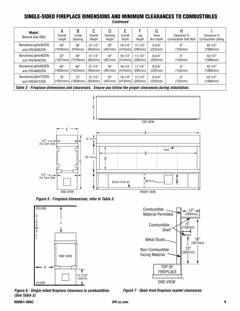
Figure 5 - Fireplace dimensions; refer to Table 3.
Model:Natural Gas (NG)
AOverall Length
BInside
Opening
COverall Height
DOpening Height
EOverall Depth
F Leg
Height
GValve
Box Depth
HClearance To
Combustible Side Wall
IClearance To
Combustible Ceiling
BarcelonaLights36ZENand VRE4636ZEN
40”(1016mm)
36”(915mm)
37-1/2”(953mm)
16”(407mm)
16-1/4”(413mm)
11-1/2”(292mm)
8-3/4”(222mm)
6”(153mm)
42-1/2”(1080mm)
BarcelonaLights48ZENand VRE4648ZEN
52”(1321mm)
48”(1219mm)
37-1/2”(953mm)
16”(407mm)
16-1/4”(413mm)
11-1/2”(292mm)
8-3/4”(222mm)
6”(153mm)
42-1/2”(1080mm)
BarcelonaLights60ZENand VRE4660ZEN
64”(1626mm)
60”(1524mm)
37-1/2”(953mm)
16”(407mm)
16-1/4”(413mm)
11-1/2”(292mm)
8-3/4”(222mm)
6”(153mm)
42-1/2”(1080mm)
BarcelonaLights72ZENand VRE4672ZEN
76”(1931mm)
72”(1829mm)
37-1/2”(953mm)
16”(407mm)
16-1/4”(413mm)
11-1/2”(292mm)
8-3/4”(222mm)
6”(153mm)
42-1/2”(1080mm)
Table 3 - Fireplace dimensions and clearances. Ensure you follow the proper clearances during installation.
FRONT VIEW
TOP VIEW
END VIEW
E
E
C
F
D
A
B
GBottom Finish Fin
Hood
1/2” (13mm)(Typ. Each Side)
6” (153mm)
20” (508mm)
1/2” (13mm)(Typ. Each Side)
I
H
END VIEW
SIDEWALL
CEILING
FLOOR
11-1/2”(292mm)
Figure 6 - Single-sided fireplace clearance to combustibles(See Table 3)
END VIEW
TOP OF FIREPLACE
Non-Combustible Facing Material
Combustible Material Permitted
CombustibleShelf
Metal Studs
12”(305mm)
6”(153mm)
18”(457mm)
12”(305mm)
Figure 7 - Open front fireplace mantel clearances
SINGLE-SIDED FIREPLACE DIMENSIONS AND MINIMUM CLEARANCES TO COMBUSTIBLESContinued
IHP.us.com 900861-00NC10
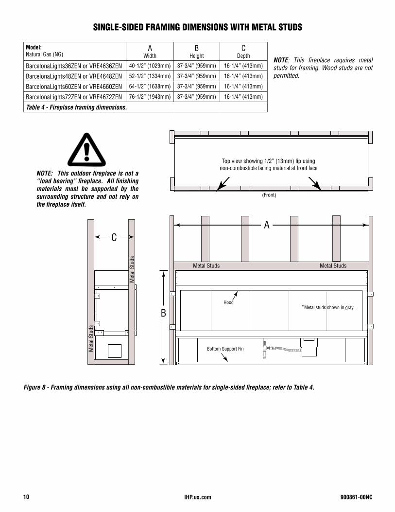
NOTE: This fireplace requires metal studs for framing. Wood studs are not permitted.
Model:Natural Gas (NG)
AWidth
BHeight
CDepth
BarcelonaLights36ZEN or VRE4636ZEN 40-1/2” (1029mm) 37-3/4” (959mm) 16-1/4” (413mm)
BarcelonaLights48ZEN or VRE4648ZEN 52-1/2” (1334mm) 37-3/4” (959mm) 16-1/4” (413mm)
BarcelonaLights60ZEN or VRE4660ZEN 64-1/2” (1638mm) 37-3/4” (959mm) 16-1/4” (413mm)
BarcelonaLights72ZEN or VRE4672ZEN 76-1/2” (1943mm) 37-3/4” (959mm) 16-1/4” (413mm)
Table 4 - Fireplace framing dimensions.
Figure 8 - Framing dimensions using all non-combustible materials for single-sided fireplace; refer to Table 4.
A
B
Metal Studs Metal Studs
*Metal studs shown in gray.
Bottom Support Fin
Hood
C
Met
al S
tuds
Met
al S
tuds
Top view showing 1/2” lip using non-combustible facing material at front face
(Front)
NOTE: This outdoor fireplace is not a “load bearing” fireplace. All finishing materials must be supported by the surrounding structure and not rely on the fireplace itself.
SINGLE-SIDED FRAMING DIMENSIONS WITH METAL STUDS
Top view showing 1/2” (13mm) lip using non-combustible facing material at front face
900861-00NC 11IHP.us.com
SEE-THROUGH FIREPLACEDIMENSIONS AND
CLEARANCES SECTION
NOTE: Preparation for the LED lighting and the inlet gas line must be planned before the fireplace is installed. See Page 5, Figure 1 for inlet gasline and Page 15 for LED lighting.
SEE-THROUGH FIREPLACE DIMENSIONS AND CLEARANCES
This fireplace comes with various boxes prepackaged inside the fireplace. Do not discard any boxes unless notes to do so. Read the list below for the contents.
Component Parts Box Contents:(1) RGB Control Assembly (includes switches and LED dimmer)(1) 12VCD Adaptor (used for LED lighting) (1) 7.5VCD Adaptor (used for valve system)(2) Pilot Covers (used inside burner pan area)(2) 6x12 Black Vents (used to ventilate enclosure) (12) Black Screws, Nuts & Washers for 6x12 vents(1) Installation manual for vent kit(1) 24-inch LED wire harness(1) 10-foot valve system (module) wire harness(1) LED 10-foot controller wire harness
Windshield Parts Box Contents:(2) Glass Windshields (inside firebox)(4) LED Retainer Clips (2 for singled-sided; 4 for see-through fireplace)(8) Glass Windshield Clips (4 for singled-sided; 8 for see-through fireplace)(2) Stainless Steel Hoods (1 for singled-sided; 2 for see-through fireplace)
LED Assemblies Box Contents:(1) LED Tray Assembly Left(1) LED Tray Assembly Right(4) LED Glass Retainer Clips & Pan Head Screws(8) Windshield Clips & Pan Head Screws
Glass Media Box Contents:(3-5) bags of diamond crystal media depending on model size (See Table 7 and Figure 33 on Page 24 for reference)
IHP.us.com 900861-00NC12
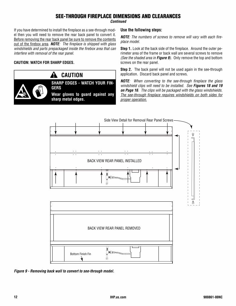
If you have determined to install the fireplace as a see-through mod-el then you will need to remove the rear back panel to convert it. Before removing the rear back panel be sure to remove the contents out of the firebox area. NOTE: The fireplace is shipped with glass windshields and parts prepackaged inside the firebox area that can interfere with removal of the rear panel.
CAUTION: WATCH FOR SHARP EDGES.
BACK VIEW REAR PANEL INSTALLED
BACK VIEW REAR PANEL REMOVED
Bottom Finish Fin
Side View Detail for Removal Rear Panel Screws
Figure 9 - Removing back wall to convert to see-through model.
Use the following steps:
NOTE: The numbers of screws to remove will vary with each fire-place model.
Step 1. Look at the back side of the fireplace. Around the outer pe-rimeter area of the frame or back wall are several screws to remove (See the shaded area in Figure 9). Only remove the top and bottom screws on the rear panel.
Step 2. The back panel will not be used again in the see-through application. Discard back panel and screws.
NOTE: When converting to the see-through fireplace the glass windshield clips will need to be installed. See Figures 18 and 19 on Page 16. The clips will be packaged with the glass windshields. The see-through fireplace requires windshields on both sides for proper operation.
SEE-THROUGH FIREPLACE DIMENSIONS AND CLEARANCESContinued
CAUTIONSHARP EDGES - WATCH YOUR FIN-GERSWear gloves to guard against any sharp metal edges.
900861-00NC 13IHP.us.com
END VIEW
TOP OF FIREPLACE
Non-combustible facing material
Combustible Material Permitted
Metal Studs
Combustible Shelf
Combustible Shelf12”
(305mm)12”
(305mm)
18” TYP.(457mm)
12”(305mm)
6”(153mm)
6”(153mm)
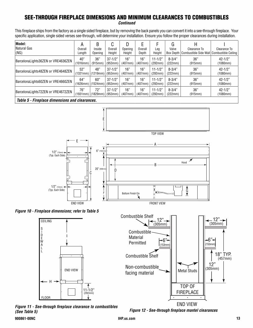
Figure 12 - See-through fireplace mantel clearances
Figure 10 - Fireplace dimensions; refer to Table 5
Model:Natural Gas (NG)
AOverall Length
BInside
Opening
COverall Height
DOpening Height
EOverall Depth
F Leg
Height
GValve
Box Depth
HClearance To
Combustible Side Wall
IClearance To
Combustible Ceiling
BarcelonaLights36ZEN or VRE4636ZEN 40”(1016mm)
36”(915mm)
37-1/2”(953mm)
16”(407mm)
16”(407mm)
11-1/2” (292mm)
8-3/4”(222mm)
36”(915mm)
42-1/2”(1080mm)
BarcelonaLights48ZEN or VRE4648ZEN 52”(1321mm)
48”(1219mm)
37-1/2”(953mm)
16”(407mm)
16”(407mm)
11-1/2” (292mm)
8-3/4”(222mm)
36”(915mm)
42-1/2”(1080mm)
BarcelonaLights60ZEN or VRE4660ZEN 64”(1626mm)
60”(1524mm)
37-1/2”(953mm)
16”(407mm)
16”(407mm)
11-1/2” (292mm)
8-3/4”(222mm)
36”(915mm)
42-1/2”(1080mm)
BarcelonaLights72ZEN or VRE4672ZEN 76”(1931mm)
72”(1829mm)
37-1/2”(953mm)
16”(407mm)
16”(407mm)
11-1/2” (292mm)
8-3/4”(222mm)
36”(915mm)
42-1/2”(1080mm)
Table 5 - Fireplace dimensions and clearances.
Figure 11 - See-through fireplace clearance to combustibles (See Table 5)
FRONT VIEW
TOP VIEW
END VIEW
E
E
C
F
D
A
B
Bottom Finish Fin
Hood
1/2” (13mm)
(Typ. Each Side)
6” (153mm)
20” (508mm)
G
1/2” (13mm)
(Typ. Each Side)
I
H
END VIEW
SIDEWALL
CEILING
FLOOR
11-1/2”(292mm)
This fireplace ships from the factory as a single sided fireplace, but by removing the back panels you can convert it into a see-through fireplace. Your specific application, single sided verses see-through, will determine your installation. Ensure you follow the proper clearances during installation.
SEE-THROUGH FIREPLACE DIMENSIONS AND MINIMUM CLEARANCES TO COMBUSTIBLESContinued
IHP.us.com 900861-00NC14
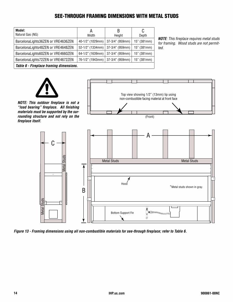
NOTE: This fireplace requires metal studs for framing. Wood studs are not permit-ted.
Model:Natural Gas (NG)
AWidth
BHeight
CDepth
BarcelonaLights36ZEN or VRE4636ZEN 40-1/2” (1029mm) 37-3/4” (959mm) 15” (381mm)
BarcelonaLights48ZEN or VRE4648ZEN 52-1/2” (1334mm) 37-3/4” (959mm) 15” (381mm)
BarcelonaLights60ZEN or VRE4660ZEN 64-1/2” (1639mm) 37-3/4” (959mm) 15” (381mm)
BarcelonaLights72ZEN or VRE4672ZEN 76-1/2” (1943mm) 37-3/4” (959mm) 15” (381mm)
Table 6 - Fireplace framing dimensions.
Figure 13 - Framing dimensions using all non-combustible materials for see-through fireplace; refer to Table 6.
NOTE: This outdoor fireplace is not a “load bearing” fireplace. All finishing materials must be supported by the sur-rounding structure and not rely on the fireplace itself.
SEE-THROUGH FRAMING DIMENSIONS WITH METAL STUDS
A
B
Metal Studs Metal Studs
*Metal studs shown in gray.
Bottom Support Fin
Hood
C
Met
al S
tuds
Met
al S
tuds
Top view showing 1/2” (13mm) lip using non-combustible facing material at front face
(Front)
Top view showing 1/2” (13mm) lip using non-combustible facing material at front face
900861-00NC 15IHP.us.com
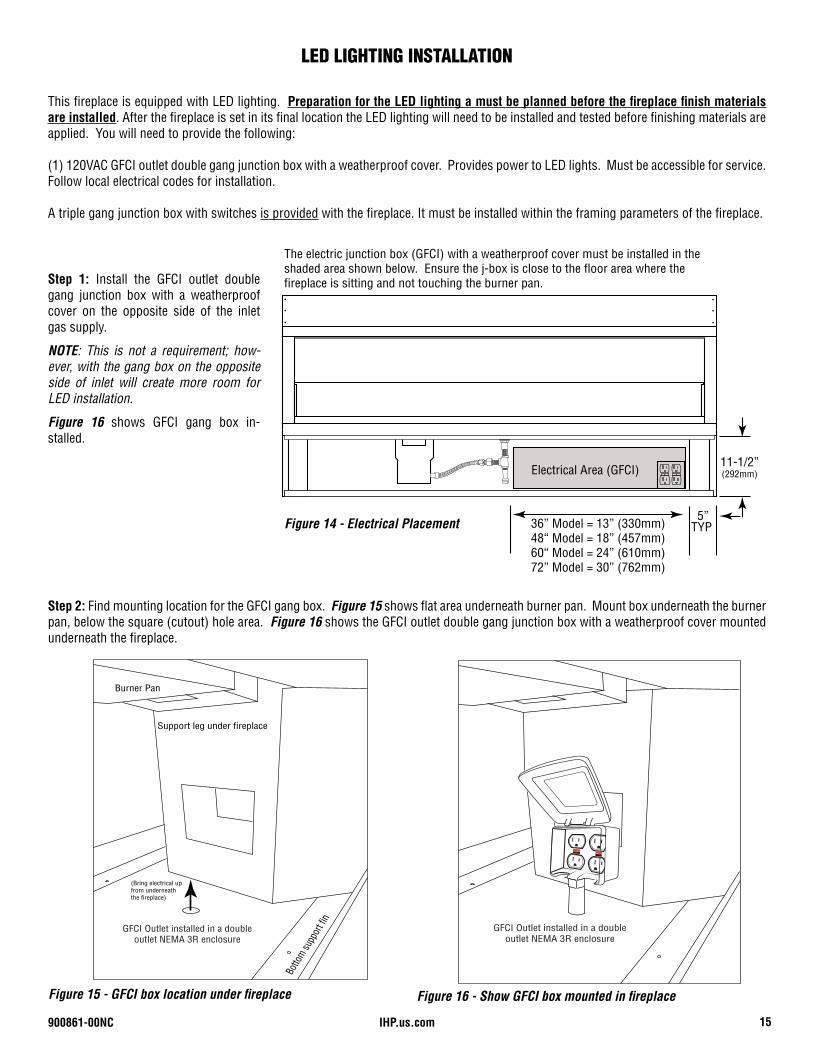
This fireplace is equipped with LED lighting. Preparation for the LED lighting a must be planned before the fireplace finish materials are installed. After the fireplace is set in its final location the LED lighting will need to be installed and tested before finishing materials are applied. You will need to provide the following:
(1) 120VAC GFCI outlet double gang junction box with a weatherproof cover. Provides power to LED lights. Must be accessible for service. Follow local electrical codes for installation.
A triple gang junction box with switches is provided with the fireplace. It must be installed within the framing parameters of the fireplace.
Step 1: Install the GFCI outlet double gang junction box with a weatherproof cover on the opposite side of the inlet gas supply.
NOTE: This is not a requirement; how-ever, with the gang box on the opposite side of inlet will create more room for LED installation.
Figure 16 shows GFCI gang box in-stalled.
Step 2: Find mounting location for the GFCI gang box. Figure 15 shows flat area underneath burner pan. Mount box underneath the burner pan, below the square (cutout) hole area. Figure 16 shows the GFCI outlet double gang junction box with a weatherproof cover mounted underneath the fireplace.
Burner Pan
Support leg under fireplace
Botto
m supp
ort f
in
GFCI Outlet installed in a double outlet NEMA 3R enclosure
(Bring electrical up from underneath the fireplace)
Figure 15 - GFCI box location under fireplace
GFCI Outlet installed in a double outlet NEMA 3R enclosure
Figure 16 - Show GFCI box mounted in fireplace
36” Model = 13” (330mm)48“ Model = 18” (457mm)60“ Model = 24” (610mm)72” Model = 30” (762mm)
5”
11-1/2”(292mm)
TYP
Electrical Area (GFCI)
The electric junction box (GFCI) with a weatherproof cover must be installed in the shaded area shown below. Ensure the j-box is close to the floor area where the fireplace is sitting and not touching the burner pan.
Figure 14 - Electrical Placement
LED LIGHTING INSTALLATION
IHP.us.com 900861-00NC16
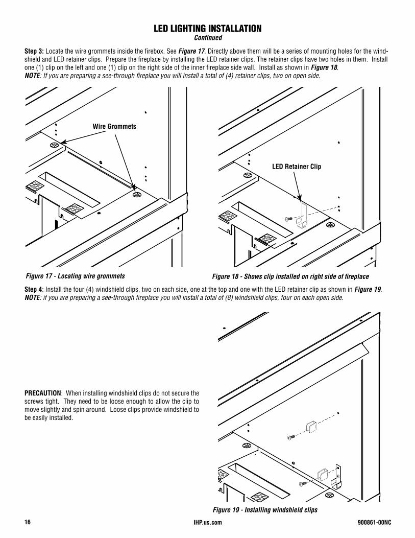
Step 3: Locate the wire grommets inside the firebox. See Figure 17. Directly above them will be a series of mounting holes for the wind-shield and LED retainer clips. Prepare the fireplace by installing the LED retainer clips. The retainer clips have two holes in them. Install one (1) clip on the left and one (1) clip on the right side of the inner fireplace side wall. Install as shown in Figure 18. NOTE: If you are preparing a see-through fireplace you will install a total of (4) retainer clips, two on open side.
Figure 18 - Shows clip installed on right side of fireplaceFigure 17 - Locating wire grommets
Step 4: Install the four (4) windshield clips, two on each side, one at the top and one with the LED retainer clip as shown in Figure 19. NOTE: if you are preparing a see-through fireplace you will install a total of (8) windshield clips, four on each open side.
Figure 19 - Installing windshield clips
PRECAUTION: When installing windshield clips do not secure the screws tight. They need to be loose enough to allow the clip to move slightly and spin around. Loose clips provide windshield to be easily installed.
LED LIGHTING INSTALLATIONContinued
Wire Grommets
LED Retainer Clip
900861-00NC 17IHP.us.com
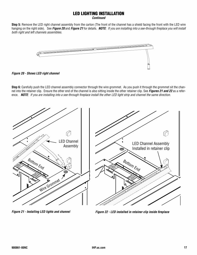
Step 6: Carefully push the LED channel assembly connector through the wire grommet. As you push it through the grommet sit the chan-nel into the retainer clip. Ensure the other end of the channel is also sitting inside the other retainer clip. See Figures 21 and 22 as a refer-ence. NOTE: If you are installing into a see-through fireplace install the other LED light strip and channel the same direction.
Wire Grommet
Bottom End
LED Channel Assembly
Figure 21 - Installing LED lights and channel Figure 22 - LED installed in retainer clip inside fireplace
Step 5: Remove the LED right channel assembly from the carton (The front of the channel has a shield facing the front with the LED wire hanging on the right side). See Figure 20 and Figure 21 for details. NOTE: If you are installing into a see-through fireplace you will install both right and left channels assemblies.
Figure 20 - Shows LED right channel
Bottom End
LED Channel Assembly Installed in retainer clip
LED LIGHTING INSTALLATIONContinued
IHP.us.com 900861-00NC18
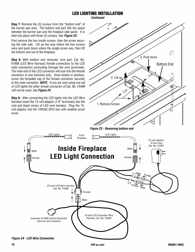
Step 7: Remove the (3) screws from the “bottom end” of the burner pan area. The bottom end part fills the space between the burner pan and the fireplace side panel. It is held into place with three (3) screws. See Figure 23.
First remove the two inside screws, then the screw secur-ing the side wall. Lift up the area where the two screws were and push down where the single screw was, then lift the bottom end out of the fireplace.
Step 8: With bottom end removed, wire part, Cat. No. F3499 (LED Wire Harness) female connectors to the LED male connectors protruding through the wire grommets. The male end of the LED connector will lock into the female connector in one direction only. Once locked in position, screw the threaded cap of the female connector securely to the male connector. NOTE: If you are only using one set of LED lights the other female connector of Cat. No. F3499 will not be used. See Figure 24.
Step 9: After connecting the LED lights into the LED Wire Harness insert the 12-volt adaptor (1/4” terminals) into the (red and black wires) of LED wire harness. Plug the 12-volt adaptor into the 120VAC GFCI box with weather proof cover.
Bottom End
1. Remove Screws
2. Lift up
3. Push down
V+
LED Lights
Male
Female Female
Male
LED LightsFrom Fireplace
Inside Fireplace LED Light Connection
12-volt adaptor; 6-foot long
Cat. No. F3481
24-inch LED Wire Harness, Cat. No. F3499
10-foot LED Controller Wire Harness, Cat. No. F3500Connects to RGB Control Assembly
(dimmer and switches)
Female Male
Female Male
Male
Female
Figure 23 - Removing bottom end
Figure 24 - LED Wire Connection
LED LIGHTING INSTALLATIONContinued
900861-00NC 19IHP.us.com
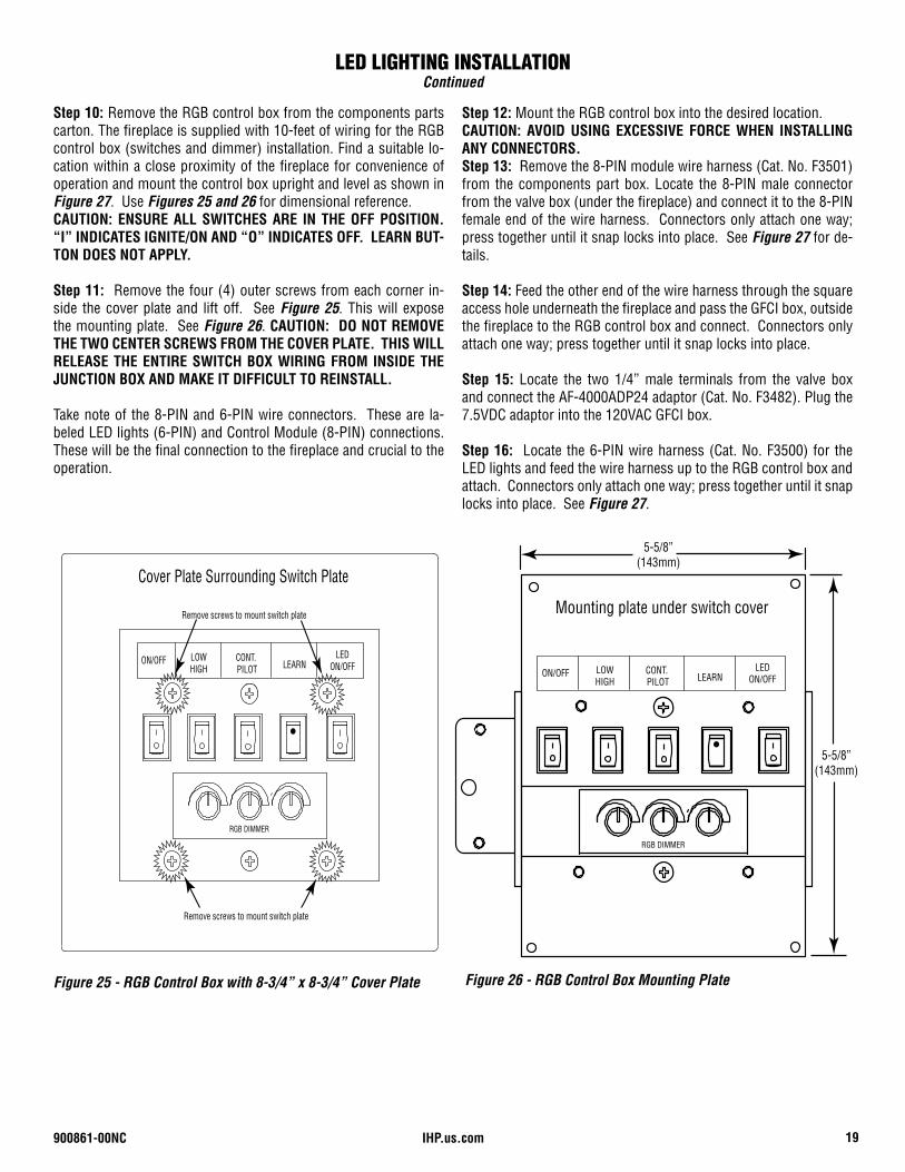
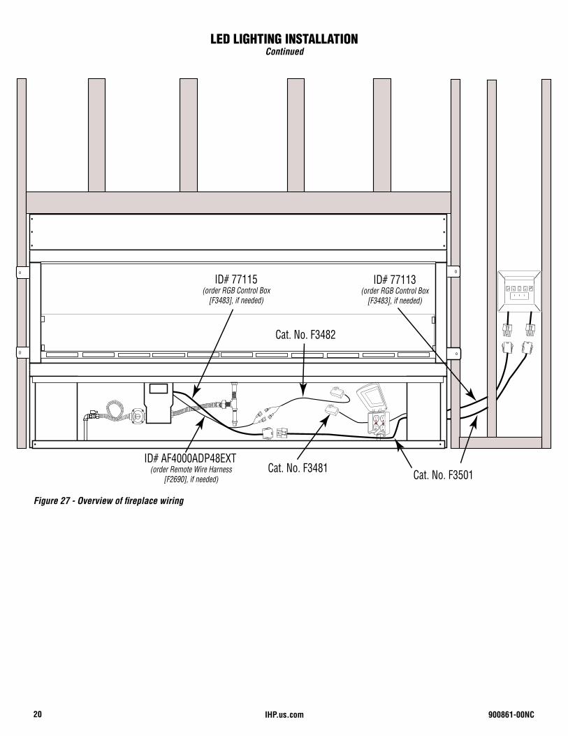
Step 10: Remove the RGB control box from the components parts carton. The fireplace is supplied with 10-feet of wiring for the RGB control box (switches and dimmer) installation. Find a suitable lo-cation within a close proximity of the fireplace for convenience of operation and mount the control box upright and level as shown in Figure 27. Use Figures 25 and 26 for dimensional reference. CAUTION: ENSURE ALL SWITCHES ARE IN THE OFF POSITION. “I” INDICATES IGNITE/ON AND “O” INDICATES OFF. LEARN BUT-TON DOES NOT APPLY.
Step 11: Remove the four (4) outer screws from each corner in-side the cover plate and lift off. See Figure 25. This will expose the mounting plate. See Figure 26. CAUTION: DO NOT REMOVE THE TWO CENTER SCREWS FROM THE COVER PLATE. THIS WILL RELEASE THE ENTIRE SWITCH BOX WIRING FROM INSIDE THE JUNCTION BOX AND MAKE IT DIFFICULT TO REINSTALL.
Take note of the 8-PIN and 6-PIN wire connectors. These are la-beled LED lights (6-PIN) and Control Module (8-PIN) connections. These will be the final connection to the fireplace and crucial to the operation.
Figure 25 - RGB Control Box with 8-3/4” x 8-3/4” Cover Plate Figure 26 - RGB Control Box Mounting Plate
Step 12: Mount the RGB control box into the desired location.CAUTION: AVOID USING EXCESSIVE FORCE WHEN INSTALLING ANY CONNECTORS.Step 13: Remove the 8-PIN module wire harness (Cat. No. F3501) from the components part box. Locate the 8-PIN male connector from the valve box (under the fireplace) and connect it to the 8-PIN female end of the wire harness. Connectors only attach one way; press together until it snap locks into place. See Figure 27 for de-tails.
Step 14: Feed the other end of the wire harness through the square access hole underneath the fireplace and pass the GFCI box, outside the fireplace to the RGB control box and connect. Connectors only attach one way; press together until it snap locks into place.
Step 15: Locate the two 1/4” male terminals from the valve box and connect the AF-4000ADP24 adaptor (Cat. No. F3482). Plug the 7.5VDC adaptor into the 120VAC GFCI box.
Step 16: Locate the 6-PIN wire harness (Cat. No. F3500) for the LED lights and feed the wire harness up to the RGB control box and attach. Connectors only attach one way; press together until it snap locks into place. See Figure 27.
LED LIGHTING INSTALLATIONContinued
RGB DIMMER
Cover Plate Surrounding Switch Plate
Remove screws to mount switch plate
Remove screws to mount switch plate
LED ON/OFF
ON/OFF LOWHIGH LEARN
CONT. PILOT
RGB DIMMER
Mounting plate under switch cover
LED ON/OFF
ON/OFF LOWHIGH LEARN
CONT. PILOT
5-5/8”(143mm)
5-5/8”(143mm)
IHP.us.com20 900861-00NC
Switch Cover
LED ON/OFF ON/OFF HI/LOW LEARNIPI/CONT PILOT
RGB DIMMER
ID# AF4000ADP48EXT(order Remote Wire Harness
[F2690], if needed)
ID# 77113(order RGB Control Box
[F3483], if needed)
Cat. No. F3482
Cat. No. F3481 Cat. No. F3501
ID# 77115(order RGB Control Box
[F3483], if needed)
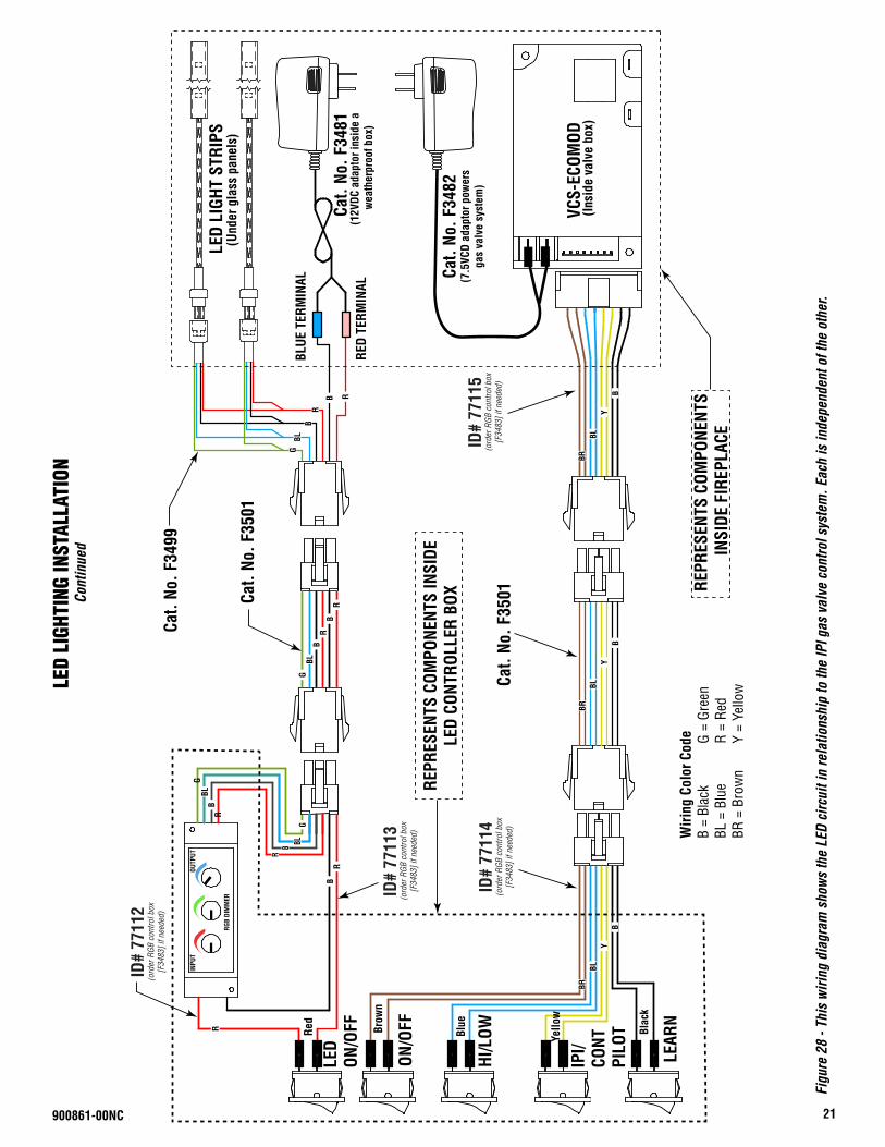
Figure 27 - Overview of fireplace wiring
LED LIGHTING INSTALLATIONContinued
21
Figu
re 2
8 - T
his
wiri
ng d
iagr
am s
how
s th
e LE
D ci
rcui
t in
rela
tions
hip
to th
e IP
I gas
val
ve c
ontro
l sys
tem
. Eac
h is
inde
pend
ent o
f the
oth
er.
LED
LIGH
TING
INST
ALLA
TION
Cont
inue
d
Cat.
No. F
3501
Cat.
No. F
3499
Cat.
No. F
3501
INPU
TOU
TPUT
RGB
DIM
MER
LEAR
N
ON/O
FF
HI/L
OW
IPI/
CONT
PILO
T
RED
TERM
INAL
BLUE
TER
MIN
AL
LED
ON/O
FF
LED
LIGH
T ST
RIPS
Cat.
No. F
3481
VCS-
ECOM
OD
(Und
er g
lass
pan
els)
(Insi
de v
alve
box
)
REPR
ESEN
TS C
OMPO
NENT
S IN
SIDE
LED
CONT
ROLL
ER B
OX
(12V
DC a
dapt
or in
side
a w
eath
erpr
oof b
ox)
REPR
ESEN
TS C
OMPO
NENT
S IN
SIDE
FIR
EPLA
CE
Cat.
No. F
3482
(7.5
VCD
adap
tor p
ower
s ga
s va
lve
syst
em)
Brow
n
Blue
Yello
w
Blac
k
Red
BRBL
BY
BRBL
BY
BLB
R
G
RB
RB BL
GBL
G
B
BR
R
BLG
B
B
R
R
BRBL
BY
R
ID#
7711
3(o
rder
RGB
con
trol b
ox
[F34
83] i
f nee
ded)
ID#
7711
4(o
rder
RGB
con
trol b
ox
[F34
83] i
f nee
ded)
ID#
7711
5(o
rder
RGB
con
trol b
ox
[F34
83] i
f nee
ded)
ID#
7711
2(o
rder
RGB
con
trol b
ox
[F34
83] i
f nee
ded)
Wiri
ng C
olor
Cod
eB
= Bl
ack
BL =
Blu
eBR
= B
row
n
G =
Gree
nR
= Re
dY
= Ye
llow
900861-00NC
IHP.us.com 900861-00NC22
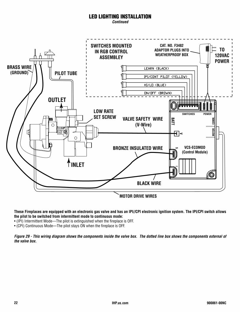
Figure 29 - This wiring diagram shows the components inside the valve box. The dotted line box shows the components external of the valve box.
LED LIGHTING INSTALLATIONContinued
VALVE SAFETY WIRE (V-Wire)
CAT. NO. F3482ADAPTOR PLUGS INTO WEATHERPROOF BOX
VCS-ECOMOD (Control Module)
1/2 PSI SPAIN
INLET
OUTLET
PILOT TUBE
SI
SWITCHES POWER
MOT
ORCO
MM
.BATT
V
BRONZE INSULATED WIRE
BLACK WIRE
BRASS WIRE(GROUND)
MOTOR DRIVE WIRES
TO 120VAC POWER
SWITCHES MOUNTED IN RGB CONTROL
ASSEMBLEY
LOW RATE SET SCREW
These Fireplaces are equipped with an electronic gas valve and has an IPI//CPI electronic ignition system. The IPI/CPI switch allows the pilot to be switched from intermittent mode to continuous mode:• (IPI) Intermittent Mode—The pilot is extinguished when the fireplace is OFF.• (CPI) Continuous Mode—The pilot stays ON when the fireplace is OFF.
900861-00NC 23IHP.us.com
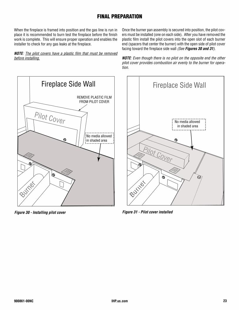
When the fireplace is framed into position and the gas line is run in place it is recommended to burn test the fireplace before the finish work is complete. This will ensure proper operation and enables the installer to check for any gas leaks at the fireplace.
NOTE: The pilot covers have a plastic film that must be removed before installing.
Figure 31 - Pilot cover installed
urne
r
Fireplace Side Wall
Pilot CoverPilot Cover
No media allowed in shaded area
Figure 30 - Installing pilot cover
Fireplace Side Wall
Pilot Cover
Burne
r
Burner End
REMOVE PLASTIC FILM FROM PILOT COVER
No media allowed in shaded area
Once the burner pan assembly is secured into position, the pilot cov-ers must be installed (one on each side). After you have removed the plastic film install the pilot covers into the open slot of each burner end (spacers that center the burner) with the open side of pilot cover facing toward the fireplace side wall (See Figures 30 and 31).
NOTE: Even though there is no pilot on the opposite end the other pilot cover provides combustion air evenly to the burner for opera-tion.
FINAL PREPARATION
IHP.us.com 900861-00NC24
FINAL PREPARATIONContinued
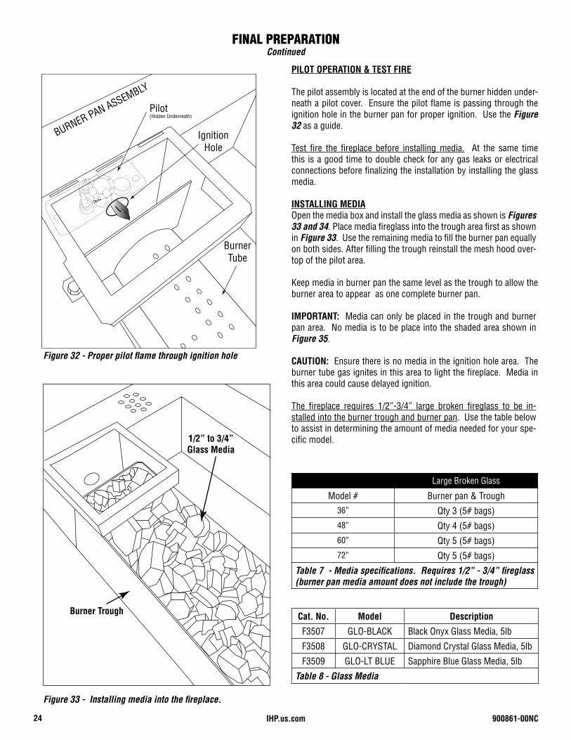
Figure 33 - Installing media into the fireplace.
Large Broken Glass
Model # Burner pan & Trough36” Qty 3 (5# bags)48” Qty 4 (5# bags)60” Qty 5 (5# bags)72” Qty 5 (5# bags)
Table 7 - Media specifications. Requires 1/2” - 3/4” fireglass (burner pan media amount does not include the trough)
BURNER PAN ASSEMBLY
Pilot (Hidden Underneath)
Burner Tube
Ignition Hole
PILOT OPERATION & TEST FIRE
The pilot assembly is located at the end of the burner hidden under-neath a pilot cover. Ensure the pilot flame is passing through the ignition hole in the burner pan for proper ignition. Use the Figure 32 as a guide.
Test fire the fireplace before installing media. At the same time this is a good time to double check for any gas leaks or electrical connections before finalizing the installation by installing the glass media.
INSTALLING MEDIAOpen the media box and install the glass media as shown is Figures 33 and 34. Place media fireglass into the trough area first as shown in Figure 33. Use the remaining media to fill the burner pan equally on both sides. After filling the trough reinstall the mesh hood over-top of the pilot area.
Keep media in burner pan the same level as the trough to allow the burner area to appear as one complete burner pan.
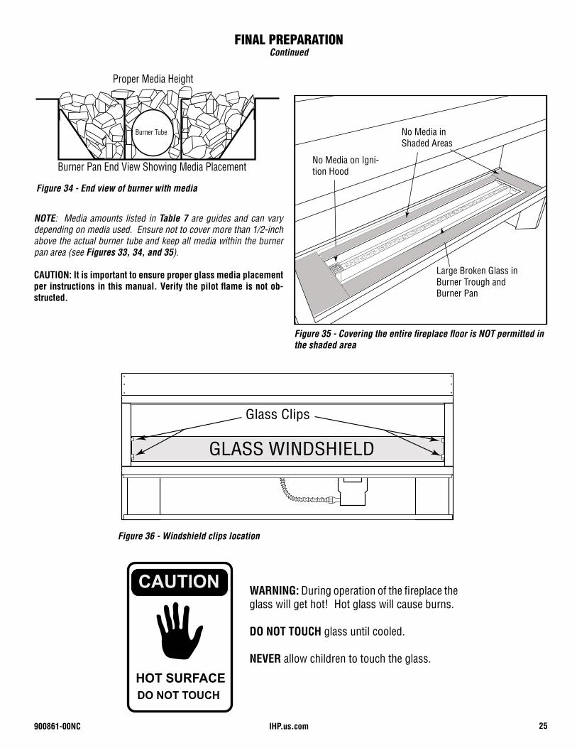
IMPORTANT: Media can only be placed in the trough and burner pan area. No media is to be place into the shaded area shown in Figure 35.
CAUTION: Ensure there is no media in the ignition hole area. The burner tube gas ignites in this area to light the fireplace. Media in this area could cause delayed ignition.
The fireplace requires 1/2”-3/4” large broken fireglass to be in-stalled into the burner trough and burner pan. Use the table below to assist in determining the amount of media needed for your spe-cific model.
Figure 32 - Proper pilot flame through ignition hole
1/2” to 3/4”Glass Media
Burner Trough Cat. No. Model Description
F3507 GLO-BLACK Black Onyx Glass Media, 5lb
F3508 GLO-CRYSTAL Diamond Crystal Glass Media, 5lb
F3509 GLO-LT BLUE Sapphire Blue Glass Media, 5lb
Table 8 - Glass Media
900861-00NC 25IHP.us.com
CAUTION
HOT SURFACEDO NOT TOUCH
FINAL PREPARATIONContinued
Figure 36 - Windshield clips location
WARNING: During operation of the fireplace the glass will get hot! Hot glass will cause burns.
DO NOT TOUCH glass until cooled.
NEVER allow children to touch the glass.
GLASS WINDSHIELD
Glass Clips
Figure 35 - Covering the entire fireplace floor is NOT permitted in the shaded area
NOTE: Media amounts listed in Table 7 are guides and can vary depending on media used. Ensure not to cover more than 1/2-inch above the actual burner tube and keep all media within the burner pan area (see Figures 33, 34, and 35).
CAUTION: It is important to ensure proper glass media placement per instructions in this manual. Verify the pilot flame is not ob-structed.
Figure 34 - End view of burner with media
Burner Pan End View Showing Media Placement
Proper Media Height
Burner Tube
Large Broken Glass inBurner Trough andBurner Pan
No Media inShaded Areas
No Media on Igni-tion Hood
IHP.us.com 900861-00NC26
FINAL PREPARATIONContinued
INSTALLING HOOD(S)
Hood Screw Locations
FRONT VIEWSIDE VIEW
Hood
(Deflector Facing Downward)
Hood DetailEnd View
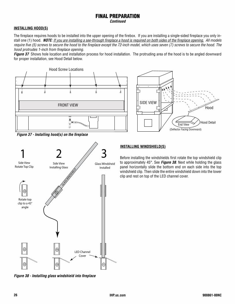
The fireplace requires hoods to be installed into the upper opening of the firebox. If you are installing a single-sided fireplace you only in-stall one (1) hood. NOTE: If you are installing a see-through fireplace a hood is required on both sides of the fireplace opening. All models require five (5) screws to secure the hood to the fireplace except the 72-inch model, which uses seven (7) screws to secure the hood. The hood protrudes 1-inch from fireplace opening.Figure 37 Shows hole location and installation process for hood installation. The protruding area of the hood is to be angled downward for proper installation, see Hood Detail below.
Figure 37 - Installing hood(s) on the fireplace
GLASS
WIN
DSHIEL
D
Side View Installing Glass
Rotate top clip to a 45°
angle
Glass WindsheidInstalled
1 2 3Side View
Rotate Top Clip
LED Channel Cover
INSTALLING WINDSHIELD(S)
Before installing the windshields first rotate the top windshield clip to approximately 45°. See Figure 38. Next while holding the glass panel horizontally slide the bottom end on each side into the top windshield clip. Then slide the entire windshield down into the lower clip and rest on top of the LED channel cover.
Figure 38 - Installing glass windshield into fireplace
900861-00NC 27IHP.us.com
BURNER PAN ASSEMBLY
Pilot (Hidden Underneath)
Burner Tube
Ignition Hole
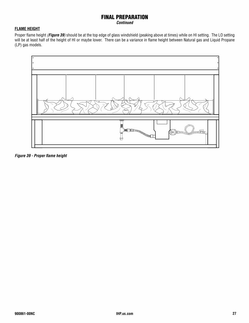
FLAME HEIGHT
Figure 39 - Proper flame height
Proper flame height (Figure 39) should be at the top edge of glass windshield (peaking above at times) while on HI setting. The LO setting will be at least half of the height of HI or maybe lower. There can be a variance in flame height between Natural gas and Liquid Propane (LP) gas models.
FINAL PREPARATIONContinued
IHP.us.com 900861-00NC28
LIGHTING INSTRUCTIONS
READ ALL WARNING AND SAFETY INFORMATION ABOVE BE-FORE ATTEMPTING TO LIGHT FIREPLACE
1. Turn ON main gas supply and check all fittings and connections for leaks with a soap and water solution.
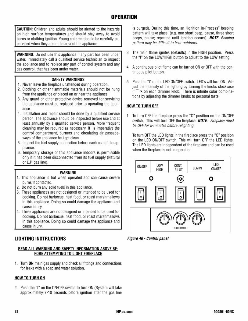
HOW TO TURN ON
2. Push the “I” on the ON/OFF switch to turn ON (System will take approximately 7-10 seconds before ignition after the gas line
Figure 40 - Control panel
WARNING: Do not use this appliance if any part has been under water. Immediately call a qualified service technician to inspect the appliance and to replace any part of control system and any gas control, that has been under water.
CAUTION: Children and adults should be alerted to the hazards on high surface temperatures and should stay away to avoid burns or clothing ignition. Young children should be carefully su-pervised when they are in the area of the appliance.
SAFETY WARNINGS 1. Never leave the fireplace unattended during operation. 2. Clothing or other flammable materials should not be hung
from the appliance or placed on or near the appliance. 3. Any guard or other protective device removed for servicing
the appliance must be replaced prior to operating the appli-ance.
4. Installation and repair should be done by a qualified service person. The appliance should be inspected before use and at least annually by a qualified service person. More frequent cleaning may be required as necessary. It is imperative the control compartment, burners and circulating air passage-ways of the appliance be kept clean.
5. Inspect the fuel supply connection before each use of the ap-pliance.
6. Temporary storage of this appliance indoors is permissible only if it has been disconnected from its fuel supply (Natural or L.P. gas line).
WARNING1. This appliance is hot when operated and can cause severe
burns if contacted.2. Do not burn any solid fuels in this appliance.3. These appliances are not designed or intended to be used for
cooking. Do not barbecue, heat food, or roast marshmallows in this appliance. Doing so could damage the appliance and cause injury.
4. These appliances are not designed or intended to be used for cooking. Do not barbecue, heat food, or roast marshmallows in this appliance. Doing so could damage the appliance and cause injury.
is purged). During this time, an “Ignition In-Process” beeping pattern will take place. (e.g. one short beep, pause, three short beeps, pause; repeated until ignition occurs). NOTE: Beeping pattern may be difficult to hear outdoors.
3. The main flame ignites (defaults) in the HIGH position. Press the “I” on the LOW/HIGH button to adjust to the LOW setting.
4. A continuous pilot flame can be turned ON or OFF with the con-tinuous pilot button.
5. Push the “I” on the LED ON/OFF switch. LED’s will turn ON. Ad-just the intensity of the lighting by turning the knobs clockwise
on each dimmer knob. There is infinite color combina-tions by adjusting the dimmer knobs to personal taste.
HOW TO TURN OFF
1. To turn OFF the fireplace press the “O” position on the ON/OFF switch. This will turn OFF the fireplace. NOTE: Fireplace must be OFF for 5-minutes before relighting.
To turn OFF the LED lights in the fireplace press the “O” position on the LED ON/OFF switch. This will turn OFF the LED lights. The LED lights are independent of the fireplace and can be used when the fireplace is not in operation.
OPERATION
RGB DIMMER
Mounting plate under switch cover
LED ON/OFF
ON/OFF LOWHIGH LEARN
CONT. PILOT
5-5/8”(143mm)
5-5/8”(143mm)
900861-00NC 29IHP.us.com
1. The fireplace should be inspected and cleaned before first use at the beginning of each season by a qualified field service per-son.
2. Any component that is found faulty must be replaced with an approved component.
3. Any tampering with or modifying the fireplace is dangerous and voids all warranties.
4. During winter months in cold climates and various seasons operation the fireplace may be affected by weather conditions. It is recommended to use a weather proof cover overtop for your fireplace to protect it from humid/rainy weather condi-tions when not in use. Heavy rains/downpours could affect the fireplace operation if not covered; if this occurs ensure you allow the fireplace time to dry out before attempting to operate. NOTE: If a combustible type cover is used over the fireplace when not in use be sure to remove it before operation to pre-vent a severe safety hazard.
5. Carbon (soot) may build up on the metal interior during heavy use. Sooting may also occur periodically under the pilot cover. CAUTION: Ensure fireplace is cool to touch and gas is turned OFF. To clean, mix several drops of dish washing liquid into a bucket of hot water. The dish soap assists in breaking up the soot and removing it from the metal.
1. Dip a scrubbing sponge into the soapy water and wipe it back and forth over the soot deposits. This breaks off the majority of the soot from the metallic surface.
2. Spray any remaining soot deposits with a combination of warm water and white vinegar mixed in a spray bottle in a half-and-half solution. White vinegar is slightly acidic and this helps break up the soot and cleans the metal effectively.
3. Run a nylon scrub brush against any stubborn soot to re-move it from the metal. Avoid using a metal scrub brush since this can result in scratching.
4. Buff the metal with a damp rag to remove any remaining soap or vinegar and then dry it with a dry rag.
6. Over time stainless steel parts can discolor when heated, usu-ally a golden or brown hue. This discoloration is normal and does not affect the performance of the appliance.
Verify proper operation after servicing.S’assurer que l’appareil fonctionne adéquatement une fois l’entretien terminé.
Inspect Burner Assembly. If it is evident that the burner is dam-aged, the burner must be replaced with one specified by the manufacturer before the appliance is put into operation.
Inspect Burner Flame and Pilot Flame Appearance Periodi-cally do a visual check of the burner flame and the pilot flame. Ensure that the burner flame appearance resembles the flame shown in Figure 39, Page 27. Refer to Figure 35 on Page 25 for more information about the pilot flame appearance. Contact a qualified service technician at once if any abnormal condition is observed.
WARNING• Turn off gas and any electrical power before servicing
the appliance.• Let fireplace completely cool before cleaning.• Failure to keep the primary air opening(s) of the
burner(s) clean may result in sooting and property damage.
• Burner Flame Pattern - If yellow tipping occurs, your fireplace could produce increased levels of carbon monoxide. Do not mistake orange flames with yellow tipping. Dirt or other fine particles enter the fireplace and burn causing brief patches of orange flame.
CAUTIONYou must keep control areas, burner and circulating air passageways of fireplace clean. Inspect these areas of fireplace before each use. Have fireplace inspected yearly by a qualified service person.
FIREPLACE MAINTENANCE
IHP.us.com 900861-00NC30
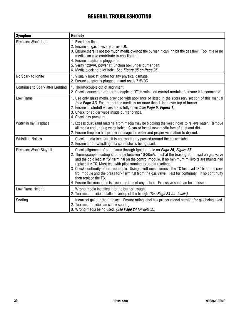
Symptom Remedy
Fireplace Won’t Light 1. Bleed gas line.2. Ensure all gas lines are turned ON.3. Ensure there is not too much media overtop the burner, it can inhibit the gas flow. Too little or no
media can also contribute to non-lighting.4. Ensure adaptor is plugged in.5. Verify 120VAC power at junction box under burner pan.6. Media blocking pilot hole. See Figure 35 on Page 25.
No Spark to Ignite 1. Visually look at igniter for any physical damage.2. Ensure adaptor is plugged in and reads 7.5VDC
Continues to Spark after Lighting 1. Thermocouple out of alignment.2. Check connection of thermocouple at “S” terminal on control module to ensure it is connected.
Low Flame 1. Use only glass media provided with appliance or listed in the accessory section of this manual (see Page 31). Ensure that the media is no more than 1-inch over top of burner.
2. Ensure all shutoff valves are is fully open (see Page 5, Figure 1).3. Check for spider webs inside burner orifice.4. Check gas pressure.
Water in my Fireplace 1. Excess dust/sand material from media may be blocking the weep holes to relieve water. Remove all media and unplug weep holes. Clean or install new media free of dust and dirt.
2. Ensure fireplace has proper drainage for water and proper ventilation to dry out.
Whistling Noises 1. Check media to ensure it is not too tightly packed around the burner tube.2. Ensure a non-whistling flex connector is being used.
Fireplace Won’t Stay Lit 1. Check alignment of pilot flame through ignition hole on Page 25, Figure 35.2. Thermocouple reading should be between 10-20mV. Test at the brass ground lead on gas valve
and the gold lead at “S” terminal on the control module. If no minimum millivolts are maintained replace the TC. Must test with pilot running to obtain readings.
3. Check continuity of thermocouple. Using a volt meter remove the TC test lead “S” from the con-trol module and the brass fork terminal from the gas valve. Test for continuity. If no continuity then replace the TC.
4. Ensure thermocouple is clean and free of any debris. Excessive soot can be an issue.
Low Flame Height 1. Wrong media installed into the burner trough.2. Too much media installed overtop of the trough (See Page 24 for details).
Sooting 1. Incorrect gas for the fireplace. Ensure rating label has proper model number for gas being used.2. Too much media can cause sooting.3. Wrong media being used. (See Page 24 for details).
GENERAL TROUBLESHOOTING
900861-00NC 31IHP.us.com
Error CodesThe control module has the ability to detect problems with the valve kit system and will initiate error codes when they occur. The error codes listed below will guide you to solving trouble-shooting issues.
Ignition Safety Error: One short beep every one second. Cause: Pilot did not light within the trial period of 50-60 seconds therefore step motor will turn gas valve to OFF position.Corrective Action: Press OFF button to clear. Wait 30 seconds and try again.
Recycle Safety Error: Two short beeps every one second.Cause: 1. Pilot automatically lights and drops out 3-times within 2-minutes causes step motor to turn gas valve to OFF position. 2. Someone has pressed the ON/OFF button 6-times within 2-minutes causing the step motor to turn gas valve to OFF position.Corrective Action: Press OFF button to clear. After 5-minutes the beeping will stop then retry.
ERROR CODE TROUBLESHOOTING
OPTIONAL ACCESSORIESPRODUCT REFERENCE INFORMATION
Cat. No. Model# Description
F3502 LPK 1 LP Conversion kit for 36-inch outdoor fireplace
F3503 LPK 2 LP Conversion kit for 48-inch outdoor fireplace
F3504 LPK 3 LP Conversion kit for 60-inch outdoor fireplace
F3505 LPK 4 LP Conversion kit for 72-inch outdoor fireplace
F3507 GLO-BLACK Black Onyx Glass Media, 5lb
F3508 GLO-CRYSTAL Diamond Crystal Glass Media, 5lb
F3509 GLO-LT BLUE Sapphire Blue Glass Media, 5lb
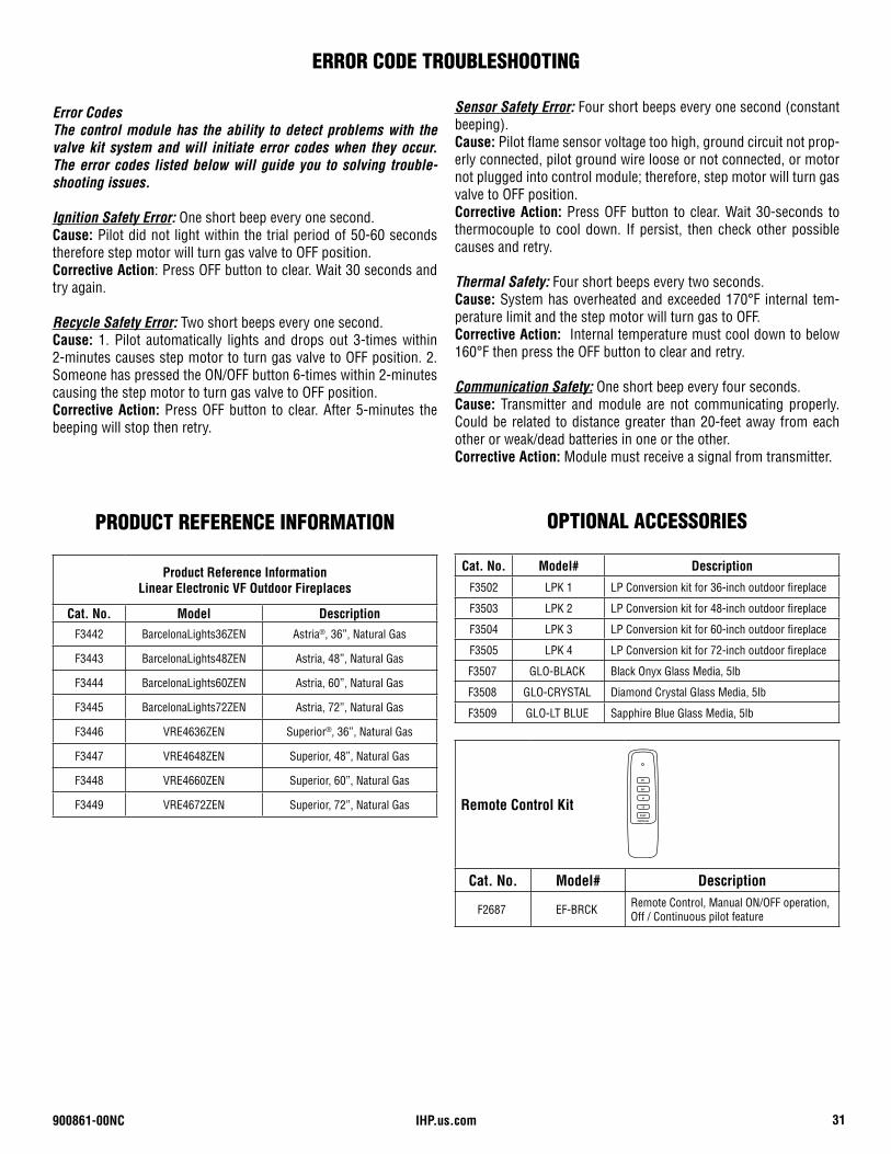
Remote Control Kit
Cat. No. Model# Description
F2687 EF-BRCK Remote Control, Manual ON/OFF operation, Off / Continuous pilot feature
ON
OFF
HI
LO
PILOT
Continuous
Sensor Safety Error: Four short beeps every one second (constant beeping).Cause: Pilot flame sensor voltage too high, ground circuit not prop-erly connected, pilot ground wire loose or not connected, or motor not plugged into control module; therefore, step motor will turn gas valve to OFF position.Corrective Action: Press OFF button to clear. Wait 30-seconds to thermocouple to cool down. If persist, then check other possible causes and retry.
Thermal Safety: Four short beeps every two seconds.Cause: System has overheated and exceeded 170°F internal tem-perature limit and the step motor will turn gas to OFF.Corrective Action: Internal temperature must cool down to below 160°F then press the OFF button to clear and retry.
Communication Safety: One short beep every four seconds.Cause: Transmitter and module are not communicating properly. Could be related to distance greater than 20-feet away from each other or weak/dead batteries in one or the other.Corrective Action: Module must receive a signal from transmitter.
Product Reference InformationLinear Electronic VF Outdoor Fireplaces
Cat. No. Model DescriptionF3442 BarcelonaLights36ZEN Astria®, 36”, Natural Gas
F3443 BarcelonaLights48ZEN Astria, 48”, Natural Gas
F3444 BarcelonaLights60ZEN Astria, 60”, Natural Gas
F3445 BarcelonaLights72ZEN Astria, 72”, Natural Gas
F3446 VRE4636ZEN Superior®, 36”, Natural Gas
F3447 VRE4648ZEN Superior, 48”, Natural Gas
F3448 VRE4660ZEN Superior, 60”, Natural Gas
F3449 VRE4672ZEN Superior, 72”, Natural Gas
IHP.us.com 900861-00NC32
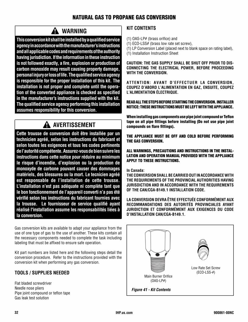
Main Burner Orifice(OAS-LP#)
Low Rate Set Screw(ECO-LSS-#)
Figure 41 - Kit Contents
Gas conversion kits are available to adapt your appliance from the use of one type of gas to the use of another. These kits contain all the necessary components needed to complete the task including labeling that must be affixed to ensure safe operation.
Kit part numbers are listed here and the following steps detail the conversion procedure. Refer to the instructions provided with the conversion kit when performing any gas conversion.
TOOLS / SUPPLIES NEEDED
Flat bladed screwdriverNeedle nose pliersPipe joint compound or teflon tapeGas leak test solution
KIT CONTENTS
(1) OAS-LP# (brass orifice) and(1) ECO-LSS# (brass low rate set screw), (1) LP Conversion Label (placed next to blank space on rating label), (1) Installation Instruction Sheet
CAUTION: THE GAS SUPPLY SHALL BE SHUT OFF PRIOR TO DIS-CONNECTING THE ELECTRICAL POWER, BEFORE PROCEEDING WITH THE CONVERSION.
ATTENTION: AVANT D’EFFECTUER LA CONVERSION, COUPEZ D’ABORD L’ALIMENTATION EN GAZ, ENSUITE, COUPEZ L’ALIMENTATION ÉLECTRIQUE.
READ ALL THE STEPS BEFORE STARTING THE CONVERSION. INSTALLER NOTICE: THESE INSTRUCTIONS MUST BE LEFT WITH THE APPLIANCE.
When installing gas components use pipe joint compound or Teflon tape on all pipe fittings before installing (Do not use pipe joint compounds on flare fittings).
THE APPLIANCE MUST BE OFF AND COLD BEFORE PERFORMING THE GAS CONVERSION.
ALL WARNINGS, PRECAUTIONS AND INSTRUCTIONS IN THE INSTAL-LATION AND OPERATION MANUAL PROVIDED WITH THE APPLIANCE APPLY TO THESE INSTRUCTIONS.
In Canada:THE CONVERSION SHALL BE CARRIED OUT IN ACCORDANCE WITH THE REQUIREMENTS OF THE PROVINCIAL AUTHORITIES HAVING JURISDICTION AND IN ACCORDANCE WITH THE REQUIREMENTS OF THE CAN/CGA-B149.1 INSTALLATION CODE.
LA CONVERSION DEVRA ÊTRE EFFECTUÉE CONFORMÉMENT AUX RECOMMANDATIONS DES AUTORITÉS PROVINCIALES AYANT JURIDICTION ET CONFORMÉMENT AUX EXIGENCES DU CODE D’INSTALLATION CAN/CGA-B149.1.
WARNINGThis conversion kit shall be installed by a qualified service agency in accordance with the manufacturer’s instructions and all applicable codes and requirements of the authority having jurisdiction. If the information in these instruction is not followed exactly, a fire, explosion or production of carbon monoxide may result causing property damage, personal injury or loss of life. The qualified service agency is responsible for the proper installation of this kit. The installation is not proper and complete until the opera-tion of the converted appliance is checked as specified in the manufacturer’s instructions supplied with the kit. The qualified service agency performing this installation assumes responsibility for this conversion.
AVERTISSEMENTCette trousse de conversion doit être installée par un technicien agréé, selon les instructions du fabricant et selon toutes les exigences et tous les codes pertinents de l’autorité compétente. Assurez-vous de bien suivre les instructions dans cette notice pour réduire au minimum le risque d’incendie, d’explosion ou la production de monoxyde de carbone pouvant causer des dommages matériels, des blessures ou la mort. Le tecnicien agréé est responsable de l’installation de cette trousse. L’installation n’est pas adéquate ni complète tant que le bon fonctionnement de l’appareil converti n’a pas été vérifié selon les instructions du fabricant fournies avec la trousse. Le fournisseur de service qualifié ayant réalisé l'installation assume les responsabilités liées à la conversion.
NATURAL GAS TO PROPANE GAS CONVERSION
900861-00NC 33IHP.us.com
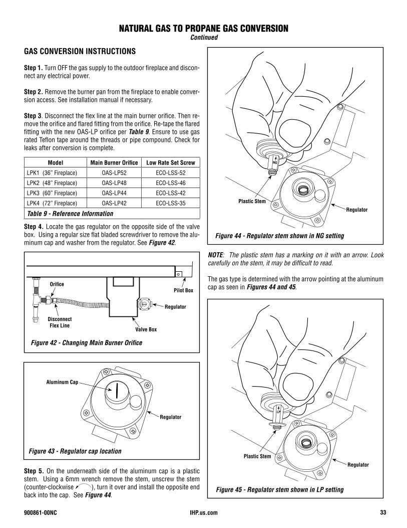
GAS CONVERSION INSTRUCTIONS
Step 1. Turn OFF the gas supply to the outdoor fireplace and discon-nect any electrical power.
Step 2. Remove the burner pan from the fireplace to enable conver-sion access. See installation manual if necessary.
Step 3. Disconnect the flex line at the main burner orifice. Then re-move the orifice and flared fitting from the orifice. Re-tape the flared fitting with the new OAS-LP orifice per Table 9. Ensure to use gas rated Teflon tape around the threads or pipe compound. Check for leaks after conversion is complete.
Step 4. Locate the gas regulator on the opposite side of the valve box. Using a regular size flat bladed screwdriver to remove the alu-minum cap and washer from the regulator. See Figure 42.
NOTE: The plastic stem has a marking on it with an arrow. Look carefully on the stem, it may be difficult to read.
The gas type is determined with the arrow pointing at the aluminum cap as seen in Figures 44 and 45.
Step 5. On the underneath side of the aluminum cap is a plastic stem. Using a 6mm wrench remove the stem, unscrew the stem (counter-clockwise ), turn it over and install the opposite end back into the cap. See Figure 44.
NATURAL GAS TO PROPANE GAS CONVERSIONContinued
Model Main Burner Orifice Low Rate Set Screw
LPK1 (36” Fireplace) OAS-LP52 ECO-LSS-52
LPK2 (48” Fireplace) OAS-LP48 ECO-LSS-46
LPK3 (60” Fireplace) OAS-LP44 ECO-LSS-42
LPK4 (72” Fireplace) OAS-LP42 ECO-LSS-35
Table 9 - Reference Information
Figure 42 - Changing Main Burner Orifice
Regulator
Valve Box
Pilot Box
DisconnectFlex Line
Orifice
Figure 43 - Regulator cap location
Regulator
Aluminum Cap
Figure 44 - Regulator stem shown in NG setting
NG
Regulator
Plastic Stem
LP
Figure 45 - Regulator stem shown in LP setting
Regulator
Plastic Stem
IHP.us.com 900861-00NC34
CAUTION: ENSURE THE ALUMINUM CAP IS INSTALLED WITH THE PLASTIC STEM SEATED COMPLETELY INTO THE CAP AND THE METAL WASHER IS INSTALLED WITH THE ALUMINUM CAP.
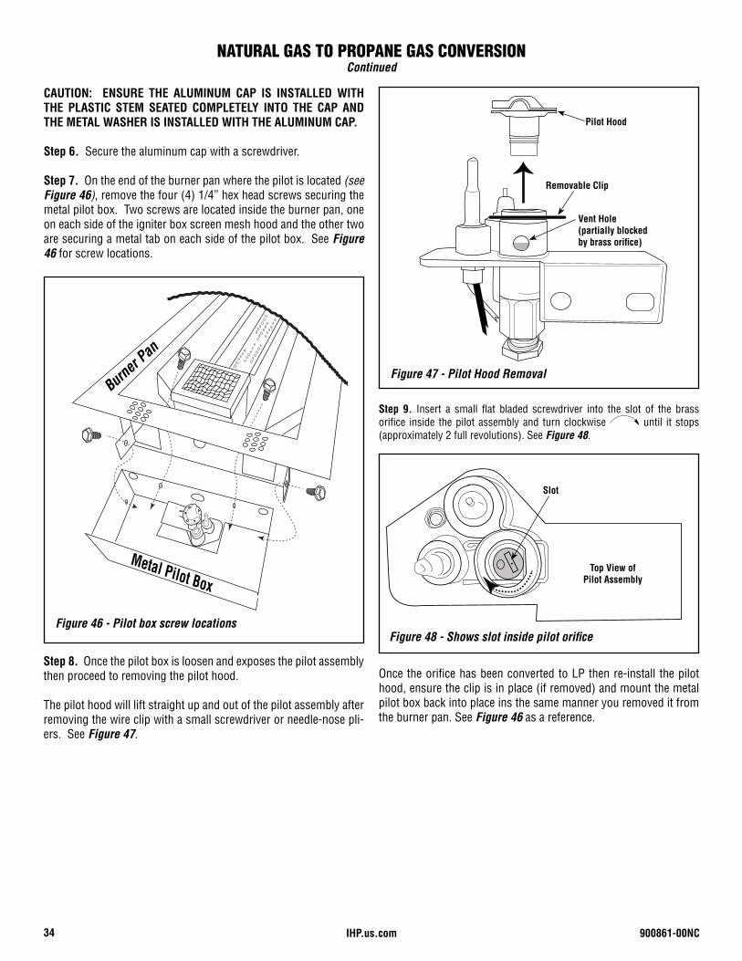
Step 6. Secure the aluminum cap with a screwdriver.
Step 7. On the end of the burner pan where the pilot is located (see Figure 46), remove the four (4) 1/4” hex head screws securing the metal pilot box. Two screws are located inside the burner pan, one on each side of the igniter box screen mesh hood and the other two are securing a metal tab on each side of the pilot box. See Figure 46 for screw locations.
Metal Pilot Box
Burner
Pan
Figure 46 - Pilot box screw locations
Step 8. Once the pilot box is loosen and exposes the pilot assembly then proceed to removing the pilot hood.
The pilot hood will lift straight up and out of the pilot assembly after removing the wire clip with a small screwdriver or needle-nose pli-ers. See Figure 47.
Step 9. Insert a small flat bladed screwdriver into the slot of the brass orifice inside the pilot assembly and turn clockwise until it stops (approximately 2 full revolutions). See Figure 48.
Once the orifice has been converted to LP then re-install the pilot hood, ensure the clip is in place (if removed) and mount the metal pilot box back into place ins the same manner you removed it from the burner pan. See Figure 46 as a reference.
NATURAL GAS TO PROPANE GAS CONVERSIONContinued
Figure 47 - Pilot Hood Removal
Removable Clip
Vent Hole(partially blocked by brass orifice)
Pilot Hood
Figure 48 - Shows slot inside pilot orifice
Top View ofPilot Assembly
Slot
900861-00NC 35IHP.us.com
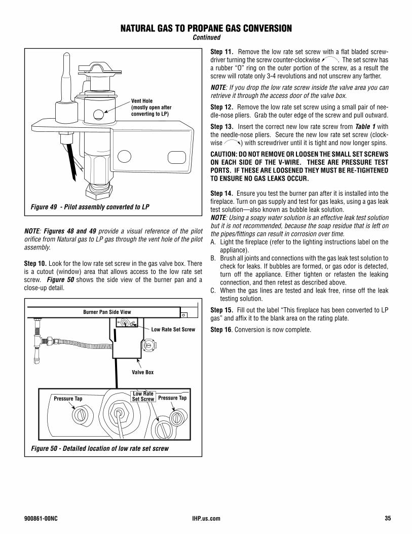
NOTE: Figures 48 and 49 provide a visual reference of the pilot orifice from Natural gas to LP gas through the vent hole of the pilot assembly.
Step 10. Look for the low rate set screw in the gas valve box. There is a cutout (window) area that allows access to the low rate set screw. Figure 50 shows the side view of the burner pan and a close-up detail.
Step 11. Remove the low rate set screw with a flat bladed screw-driver turning the screw counter-clockwise . The set screw has a rubber “O” ring on the outer portion of the screw, as a result the screw will rotate only 3-4 revolutions and not unscrew any farther.
NOTE: If you drop the low rate screw inside the valve area you can retrieve it through the access door of the valve box.
Step 12. Remove the low rate set screw using a small pair of nee-dle-nose pliers. Grab the outer edge of the screw and pull outward.
Step 13. Insert the correct new low rate screw from Table 1 with the needle-nose pliers. Secure the new low rate set screw (clock-wise ) with screwdriver until it is tight and now longer spins.
CAUTION: DO NOT REMOVE OR LOOSEN THE SMALL SET SCREWS ON EACH SIDE OF THE V-WIRE. THESE ARE PRESSURE TEST PORTS. IF THESE ARE LOOSENED THEY MUST BE RE-TIGHTENED TO ENSURE NO GAS LEAKS OCCUR.
Step 14. Ensure you test the burner pan after it is installed into the fireplace. Turn on gas supply and test for gas leaks, using a gas leak test solution—also known as bubble leak solution.NOTE: Using a soapy water solution is an effective leak test solution but it is not recommended, because the soap residue that is left on the pipes/fittings can result in corrosion over time.A. Light the fireplace (refer to the lighting instructions label on the
appliance).B. Brush all joints and connections with the gas leak test solution to
check for leaks. If bubbles are formed, or gas odor is detected, turn off the appliance. Either tighten or refasten the leaking connection, and then retest as described above.
C. When the gas lines are tested and leak free, rinse off the leak testing solution.
Step 15. Fill out the label “This fireplace has been converted to LP gas” and affix it to the blank area on the rating plate.
Step 16. Conversion is now complete.
NATURAL GAS TO PROPANE GAS CONVERSIONContinued
Figure 49 - Pilot assembly converted to LP
Vent Hole(mostly open after converting to LP)
Figure 50 - Detailed location of low rate set screw
Pressure Tap Pressure Tap
Low Rate Set Screw
Valve Box
Burner Pan Side View
Low Rate Set Screw
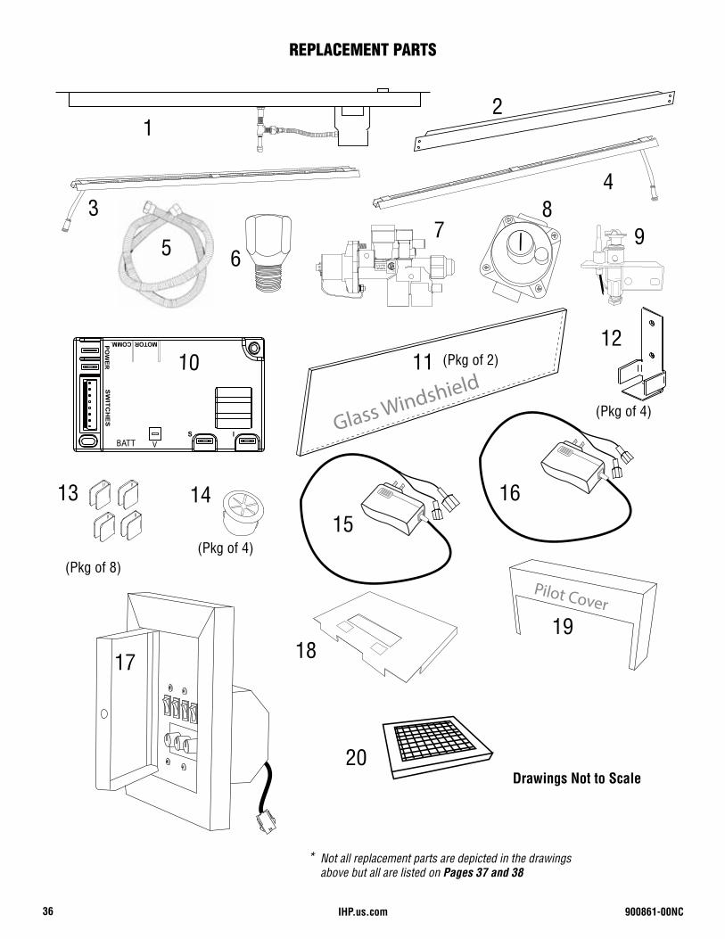
IHP.us.com 900861-00NC36
REPLACEMENT PARTS
Glass Windshield
12
Drawings Not to Scale
13
5
1112
* Not all replacement parts are depicted in the drawings above but all are listed on Pages 37 and 38
9
S I
SW
ITC
HE
SP
OW
ER
MOTOR COMM.
BATT V
151614
17
Pilot Cover
18
1/2 PSI SPAIN
7
43
6
19
(Pkg of 8)(Pkg of 4)
(Pkg of 4)
8
10
20
(Pkg of 2)
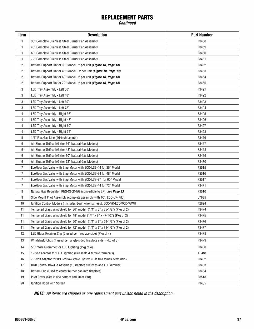
900861-00NC 37IHP.us.com
REPLACEMENT PARTSContinued
Item Description Part Number1 36” Complete Stainless Steel Burner Pan Assembly F3458
1 48” Complete Stainless Steel Burner Pan Assembly F3459
1 60” Complete Stainless Steel Burner Pan Assembly F3460
1 72” Complete Stainless Steel Burner Pan Assembly F3461
2 Bottom Support Fin for 36” Model - 2 per unit (Figure 10, Page 13) F3462
2 Bottom Support Fin for 48” Model - 2 per unit (Figure 10, Page 13) F3463
2 Bottom Support Fin for 60” Model - 2 per unit (Figure 10, Page 13) F3464
2 Bottom Support Fin for 72” Model - 2 per unit (Figure 10, Page 13) F3465
3 LED Tray Assembly - Left 36” F3491
3 LED Tray Assembly - Left 48” F3492
3 LED Tray Assembly - Left 60” F3493
3 LED Tray Assembly - Left 72” F3494
4 LED Tray Assembly - Right 36” F3495
4 LED Tray Assembly - Right 48” F3496
4 LED Tray Assembly - Right 60” F3497
4 LED Tray Assembly - Right 72” F3498
5 1/2” Flex Gas Line (46-inch Length) F3466
6 Air Shutter Orifice NG (for 36” Natural Gas Models) F3467
6 Air Shutter Orifice NG (for 48” Natural Gas Models) F3468
6 Air Shutter Orifice NG (for 60” Natural Gas Models) F3469
6 Air Shutter Orifice NG (for 72” Natural Gas Models) F3470
7 EcoFlow Gas Valve with Step Motor with ECO-LSS-44 for 36” Model F3515
7 EcoFlow Gas Valve with Step Motor with ECO-LSS-34 for 48” Model F3516
7 EcoFlow Gas Valve with Step Motor with ECO-LSS-27 for 60” Model F3517
7 EcoFlow Gas Valve with Step Motor with ECO-LSS-44 for 72” Model F3471
8 Natural Gas Regulator, REG-C80K-NG (convertible to LP). See Page 33 F3510
9 Side Mount Pilot Assembly (complete assembly with TC), ECO-VK-Pilot J7935
10 Ignition Control Module ( includes 8-pin wire harness), ECO-VK-ECOMOD-WWH F2694
11 Tempered Glass Windshield for 36” model (1/4” x 8” x 35-1/2”) (Pkg of 2) F3474
11 Tempered Glass Windshield for 48” model (1/4” x 8” x 47-1/2”) (Pkg of 2) F3475
11 Tempered Glass Windshield for 60” model (1/4” x 8” x 59-1/2”) (Pkg of 2) F3476
11 Tempered Glass Windshield for 72” model (1/4” x 8” x 71-1/2”) (Pkg of 2) F3477
12 LED Glass Retainer Clip (2 used per fireplace side) (Pkg of 4) F3478
13 Windshield Clips (4 used per single-sided fireplace side) (Pkg of 8) F3479
14 5/8” Wire Grommet for LED Lighting (Pkg of 4) F3480
15 12-volt adaptor for LED Lighting (Has male & female terminals) F3481
16 7.5-volt adaptor for IPI Ecoflow Valve System (Has two female terminals) F3482
17 RGB Control Box/Lid Assembly (Fireplace switches and LED dimmer) F3483
18 Bottom End (Used to center burner pan into fireplace) F3484
19 Pilot Cover (Sits inside bottom end, item #18) F3518
20 Ignition Hood with Screen F3485
NOTE: All items are shipped as one replacement part unless noted in the description.
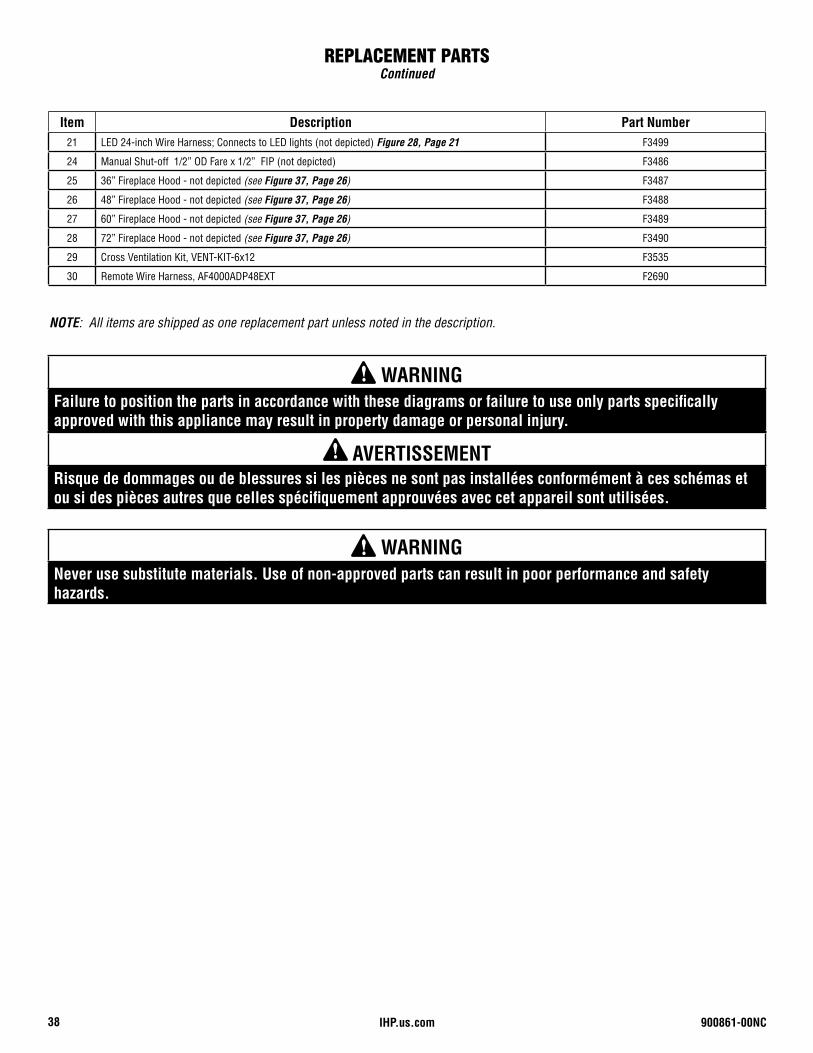
IHP.us.com 900861-00NC38
REPLACEMENT PARTSContinued
Item Description Part Number21 LED 24-inch Wire Harness; Connects to LED lights (not depicted) Figure 28, Page 21 F3499
24 Manual Shut-off 1/2” OD Fare x 1/2” FIP (not depicted) F3486
25 36” Fireplace Hood - not depicted (see Figure 37, Page 26) F3487
26 48” Fireplace Hood - not depicted (see Figure 37, Page 26) F3488
27 60” Fireplace Hood - not depicted (see Figure 37, Page 26) F3489
28 72” Fireplace Hood - not depicted (see Figure 37, Page 26) F3490
29 Cross Ventilation Kit, VENT-KIT-6x12 F3535
30 Remote Wire Harness, AF4000ADP48EXT F2690
NOTE: All items are shipped as one replacement part unless noted in the description.
WARNING Never use substitute materials. Use of non-approved parts can result in poor performance and safety hazards.
WARNING Failure to position the parts in accordance with these diagrams or failure to use only parts specifically approved with this appliance may result in property damage or personal injury.
AVERTISSEMENT Risque de dommages ou de blessures si les pièces ne sont pas installées conformément à ces schémas et ou si des pièces autres que celles spécifiquement approuvées avec cet appareil sont utilisées.
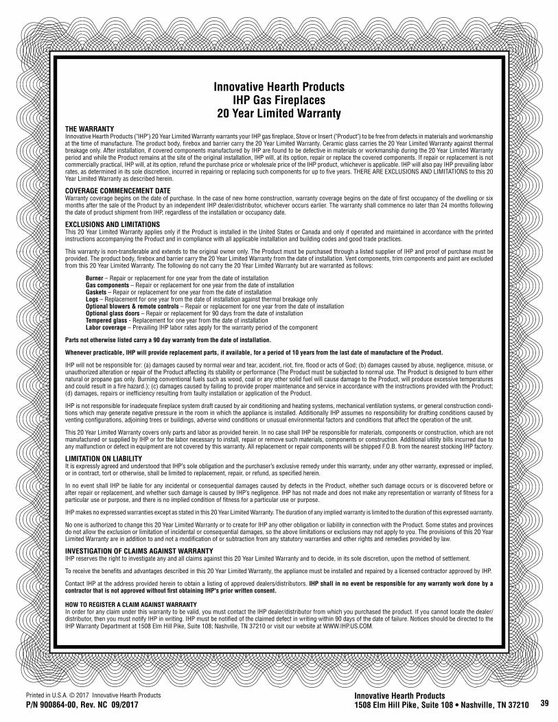
39Printed in U.S.A. © 2017 Innovative Hearth Products
P/N 900864-00, Rev. NC 09/2017Innovative Hearth Products1508 Elm Hill Pike, Suite 108 • Nashville, TN 37210
Innovative Hearth ProductsIHP Gas Fireplaces
20 Year Limited WarrantyTHE WARRANTYInnovative Hearth Products ("IHP") 20 Year Limited Warranty warrants your IHP gas fireplace, Stove or Insert ("Product") to be free from defects in materials and workmanship at the time of manufacture. The product body, firebox and barrier carry the 20 Year Limited Warranty. Ceramic glass carries the 20 Year Limited Warranty against thermal breakage only. After installation, if covered components manufactured by IHP are found to be defective in materials or workmanship during the 20 Year Limited Warranty period and while the Product remains at the site of the original installation, IHP will, at its option, repair or replace the covered components. If repair or replacement is not commercially practical, IHP will, at its option, refund the purchase price or wholesale price of the IHP product, whichever is applicable. IHP will also pay IHP prevailing labor rates, as determined in its sole discretion, incurred in repairing or replacing such components for up to five years. THERE ARE EXCLUSIONS AND LIMITATIONS to this 20 Year Limited Warranty as described herein.
COVERAGE COMMENCEMENT DATEWarranty coverage begins on the date of purchase. In the case of new home construction, warranty coverage begins on the date of first occupancy of the dwelling or six months after the sale of the Product by an independent IHP dealer/distributor, whichever occurs earlier. The warranty shall commence no later than 24 months following the date of product shipment from IHP, regardless of the installation or occupancy date.
EXCLUSIONS AND LIMITATIONSThis 20 Year Limited Warranty applies only if the Product is installed in the United States or Canada and only if operated and maintained in accordance with the printed instructions accompanying the Product and in compliance with all applicable installation and building codes and good trade practices.
This warranty is non-transferable and extends to the original owner only. The Product must be purchased through a listed supplier of IHP and proof of purchase must be provided. The product body, firebox and barrier carry the 20 Year Limited Warranty from the date of installation. Vent components, trim components and paint are excluded from this 20 Year Limited Warranty. The following do not carry the 20 Year Limited Warranty but are warranted as follows:
Burner – Repair or replacement for one year from the date of installationGas components – Repair or replacement for one year from the date of installationGaskets – Repair or replacement for one year from the date of installationLogs – Replacement for one year from the date of installation against thermal breakage onlyOptional blowers & remote controls – Repair or replacement for one year from the date of installationOptional glass doors – Repair or replacement for 90 days from the date of installationTempered glass - Replacement for one year from the date of installationLabor coverage – Prevailing IHP labor rates apply for the warranty period of the component
Parts not otherwise listed carry a 90 day warranty from the date of installation.
Whenever practicable, IHP will provide replacement parts, if available, for a period of 10 years from the last date of manufacture of the Product.
IHP will not be responsible for: (a) damages caused by normal wear and tear, accident, riot, fire, flood or acts of God; (b) damages caused by abuse, negligence, misuse, or unauthorized alteration or repair of the Product affecting its stability or performance (The Product must be subjected to normal use. The Product is designed to burn either natural or propane gas only. Burning conventional fuels such as wood, coal or any other solid fuel will cause damage to the Product, will produce excessive temperatures and could result in a fire hazard.); (c) damages caused by failing to provide proper maintenance and service in accordance with the instructions provided with the Product; (d) damages, repairs or inefficiency resulting from faulty installation or application of the Product.
IHP is not responsible for inadequate fireplace system draft caused by air conditioning and heating systems, mechanical ventilation systems, or general construction condi-tions which may generate negative pressure in the room in which the appliance is installed. Additionally IHP assumes no responsibility for drafting conditions caused by venting configurations, adjoining trees or buildings, adverse wind conditions or unusual environmental factors and conditions that affect the operation of the unit.
This 20 Year Limited Warranty covers only parts and labor as provided herein. In no case shall IHP be responsible for materials, components or construction, which are not manufactured or supplied by IHP or for the labor necessary to install, repair or remove such materials, components or construction. Additional utility bills incurred due to any malfunction or defect in equipment are not covered by this warranty. All replacement or repair components will be shipped F.O.B. from the nearest stocking IHP factory.
LIMITATION ON LIABILITYIt is expressly agreed and understood that IHP’s sole obligation and the purchaser’s exclusive remedy under this warranty, under any other warranty, expressed or implied, or in contract, tort or otherwise, shall be limited to replacement, repair, or refund, as specified herein.
In no event shall IHP be liable for any incidental or consequential damages caused by defects in the Product, whether such damage occurs or is discovered before or after repair or replacement, and whether such damage is caused by IHP’s negligence. IHP has not made and does not make any representation or warranty of fitness for a particular use or purpose, and there is no implied condition of fitness for a particular use or purpose.
IHP makes no expressed warranties except as stated in this 20 Year Limited Warranty. The duration of any implied warranty is limited to the duration of this expressed warranty.
No one is authorized to change this 20 Year Limited Warranty or to create for IHP any other obligation or liability in connection with the Product. Some states and provinces do not allow the exclusion or limitation of incidental or consequential damages, so the above limitations or exclusions may not apply to you. The provisions of this 20 Year Limited Warranty are in addition to and not a modification of or subtraction from any statutory warranties and other rights and remedies provided by law.
INVESTIGATION OF CLAIMS AGAINST WARRANTYIHP reserves the right to investigate any and all claims against this 20 Year Limited Warranty and to decide, in its sole discretion, upon the method of settlement.
To receive the benefits and advantages described in this 20 Year Limited Warranty, the appliance must be installed and repaired by a licensed contractor approved by IHP.
Contact IHP at the address provided herein to obtain a listing of approved dealers/distributors. IHP shall in no event be responsible for any warranty work done by a contractor that is not approved without first obtaining IHP's prior written consent. HOW TO REGISTER A CLAIM AGAINST WARRANTYIn order for any claim under this warranty to be valid, you must contact the IHP dealer/distributor from which you purchased the product. If you cannot locate the dealer/distributor, then you must notify IHP in writing. IHP must be notified of the claimed defect in writing within 90 days of the date of failure. Notices should be directed to the IHP Warranty Department at 1508 Elm Hill Pike, Suite 108; Nashville, TN 37210 or visit our website at WWW.IHP.US.COM.

40
IHP reserves the right to make changes at any time, without notice, in design, materials, specifications, prices and also to discontinue colors, styles and products. Consult your local distributor for fireplace code information.
Printed in U.S.A. © 2017 Innovative Hearth ProductsP/N 900861-00 Rev. NC 10/2017 1508 Elm Hill Pike, Suite 108 • Nashville, TN 37210
P900861-00
IHP.us.comRecord the following important information about your fireplace:
Fireplace model number
Fireplace serial number
Date fireplace was Installed
Type of gas fireplace uses
Dealer name