otgb - student symposium poster
TRANSCRIPT
TEMPLATE DESIGN © 2007
www.PosterPresentations.com
Implementation of safety control systems in laboratory
station for advanced research in energy storage
Introduction
Automated systems have proven to improve safetyand increase productivity. In compliance with OregonTech’s Safety Policy, this project will outline safe andreliable equipment to further the research in energystorage on campus.
Objectives
Method Results
Renewable Energy EngineeringPaulo Vasconcelos, Frank Rytkonen, PE, Dr. Claudia Torres Garibay, Dr. Lawrence J Wolf, PE
The main objectives of this project are:
1. To develop a Safety Study Analysis of incidentcauses
2. To design and implement safety control systems3. To develop engineering documentation and
training
Motivation:• Safety is a priority for Oregon Tech.• Help fellow students to focus on their research not on monitoring the system.
Fig. 2. Damage inside glovebox after incident.
Fig. 6. Protection Layers. Old system had only thefirst layer of protection.
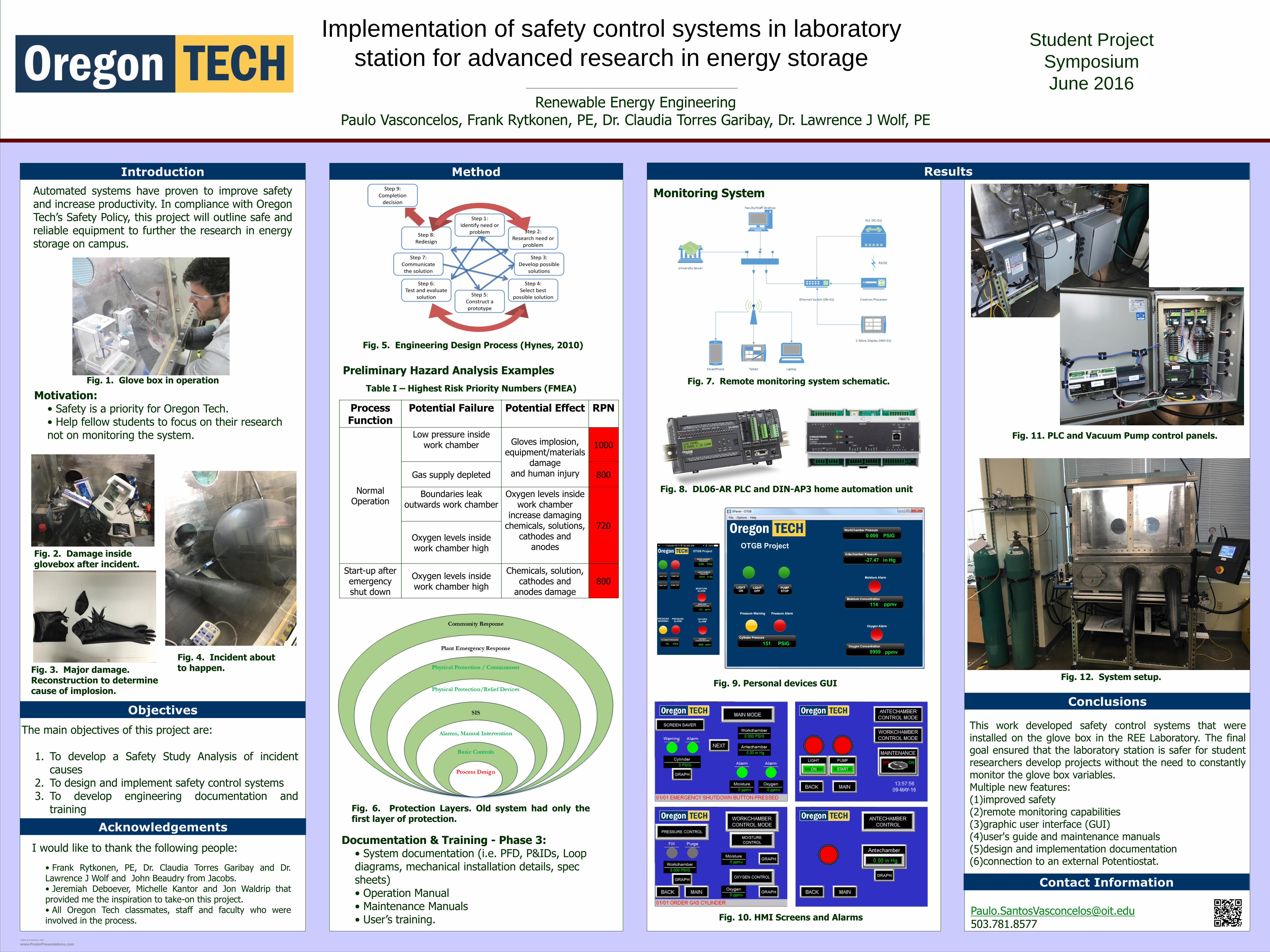
Fig. 7. Remote monitoring system schematic.
Acknowledgements
I would like to thank the following people:
• Frank Rytkonen, PE, Dr. Claudia Torres Garibay and Dr.Lawrence J Wolf and John Beaudry from Jacobs.• Jeremiah Deboever, Michelle Kantor and Jon Waldrip thatprovided me the inspiration to take-on this project.• All Oregon Tech classmates, staff and faculty who wereinvolved in the process.
Conclusions
Fig. 3. Major damage. Reconstruction to determine cause of implosion.
Preliminary Hazard Analysis ExamplesFig. 1. Glove box in operation
Documentation & Training - Phase 3:• System documentation (i.e. PFD, P&IDs, Loop diagrams, mechanical installation details, spec sheets)• Operation Manual• Maintenance Manuals• User’s training.
Process Function
Potential Failure Potential Effect RPN
Normal Operation
Low pressure inside work chamber Gloves implosion,
equipment/materials damage
and human injury
1000
Gas supply depleted 800
Boundaries leak outwards work chamber
Oxygen levels inside work chamber
increase damaging chemicals, solutions,
cathodes and anodes
720
Oxygen levels inside work chamber high
Start-up after emergency shut down
Oxygen levels inside work chamber high
Chemicals, solution, cathodes and
anodes damage800
Table I – Highest Risk Priority Numbers (FMEA)
Monitoring System
This work developed safety control systems that wereinstalled on the glove box in the REE Laboratory. The finalgoal ensured that the laboratory station is safer for studentresearchers develop projects without the need to constantlymonitor the glove box variables.Multiple new features:(1)improved safety(2)remote monitoring capabilities(3)graphic user interface (GUI)(4)user's guide and maintenance manuals(5)design and implementation documentation(6)connection to an external Potentiostat.
Contact Information
Fig. 9. Personal devices GUI
Fig. 4. Incident about to happen.
Fig. 5. Engineering Design Process (Hynes, 2010)
Fig. 11. PLC and Vacuum Pump control panels.
Fig. 8. DL06-AR PLC and DIN-AP3 home automation unit
Fig. 12. System setup.
Student Project
Symposium
June 2016
Fig. 10. HMI Screens and Alarms