oscillator dr.debashis de associate professor west bengal university of technology
TRANSCRIPT
OscillatorDr.Debashis DeAssociate ProfessorWest Bengal University of Technology

12-1 Introduction 12-2 Classifications of Oscillators 12-3 Circuit Analysis of a General Oscillator 12-4 Conditions for Oscillation: Barkhausen- Criteria 12-5 Tuned Oscillator 12-6 Crystal Oscillator 12-7 Applications of Oscillators

In this chapter we will explore the working principle of the oscillator. Generally speaking, the oscillator produces sinusoidal and other waveforms.
Beginning with a detailed circuit analysis of the oscillator, we will proceed to discuss the conditions and frequency of oscillation.
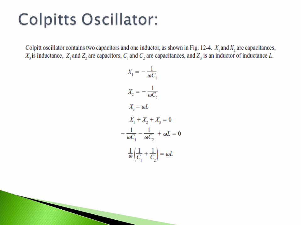
Following this, the different types of oscillators—Tuned oscillator, Hartley oscillator, Colpitts oscillator, Clapp oscillator, Phase-shift oscillator, Crystal oscillator and Wien-bridge oscillator—will be examined with detailed mathematical analysis and illustrations.
The chapter ends with an overview of the applications of the oscillator.
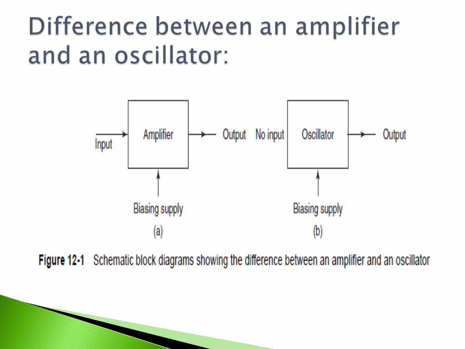
An oscillator is an electronic system. It comprises active and passive circuit elements
and sinusoidal produces repetitive waveforms at the output without the application of a direct external input signal to the circuit.
It converts the dc power from the source to ac power in the load. A rectifier circuit converts ac to dc power, but an oscillator converts dc noise signal/power to its ac equivalent.
The general form of a harmonic oscillator is an electronic amplifier with the output attached to a narrow-band electronic filter, and the output of the filter attached to the input of the amplifier.
In this chapter, the oscillator analysis is done in two methods—first by a general analysis, considering all other circuits are the special form of a common generalized circuit and second, using the individual circuit KVL analysis.

Oscillators are classified based on the type of the output waveform.
If the generated waveform is sinusoidal or close to sinusoidal (with a certain frequency) then the oscillator is said to be a Sinusoidal Oscillator.
If the output waveform is non-sinusoidal, which refers to square/saw-tooth waveforms, the oscillator is said to be a
Relaxation Oscillator. An oscillator has a positive feedback with the loop
gain infinite. Feedback-type sinusoidal oscillators can be classified as LC (inductor-capacitor) and RC (resistor-capacitor) oscillators.
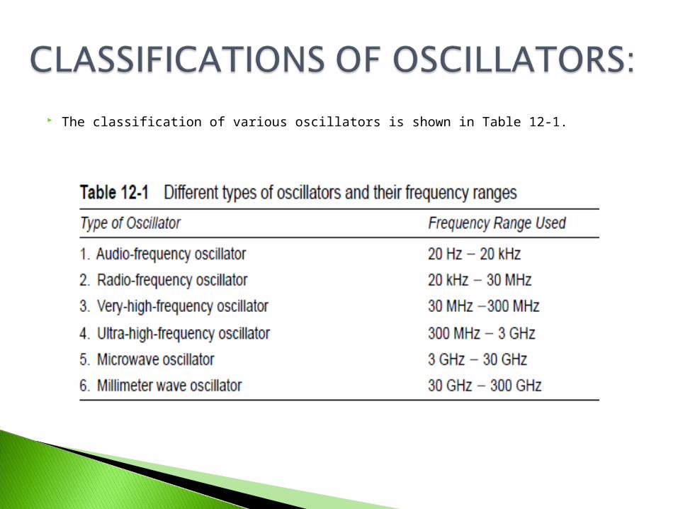
The classification of various oscillators is shown in Table 12-1.
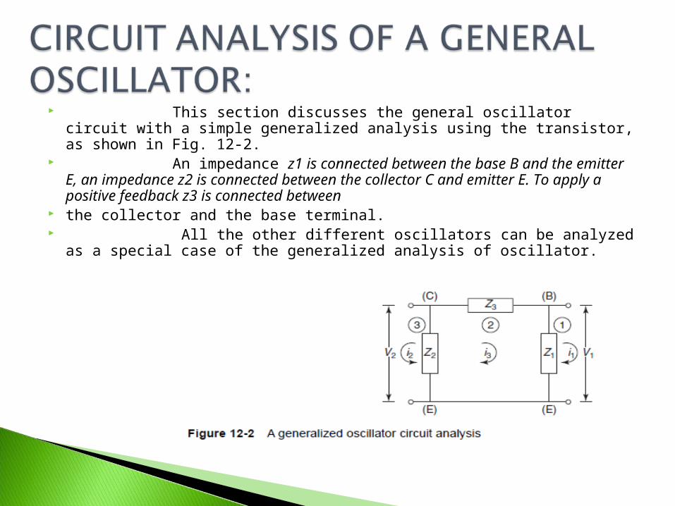
This section discusses the general oscillator circuit with a simple generalized analysis using the transistor, as shown in Fig. 12-2.
An impedance z1 is connected between the base B and the emitter E, an impedance z2 is connected between the collector C and emitter E. To apply a positive feedback z3 is connected between
the collector and the base terminal. All the other different oscillators can be analyzed as a special
case of the generalized analysis of oscillator.
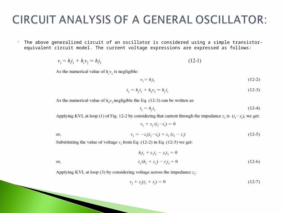
The above generalized circuit of an oscillator is considered using a simple transistor-equivalent circuit model. The current voltage expressions are expressed as follows:


Advantages of Wien-Bridge Oscillator: 1. The frequency of oscillation can be easily varied just by
changing RC network 2. High gain due to two-stage amplifier 3. Stability is high
Disadvantages of Wien-Bridge Oscillator The main disadvantage of the Wien-bridge oscillator is that a high
frequency of oscillation cannot be generated.

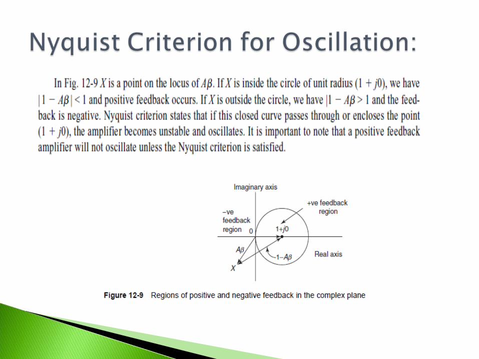
Nyquist criterion states that if this closed curve passes through or encloses the point (1 + j0), the amplifier becomes unstable and oscillates.
It is important to note that a positive feedback amplifier will not oscillate unless the Nyquist criterion is satisfied.
In the steady state condition the loop gain becomes unity and the oscillations are sustained, the frequency of oscillations is controlled by the frequency-determining network of the oscillator.
The RC and a LC combination circuits are used in oscillators to serve as the frequency-determining network.
Let us summarize the key necessities of a feedback oscillator. 1. Amplifier with positive feedback produces a negative
resistance in the system. 2. A frequency-determining network creates oscillations at
certain required frequencies. 3. System non-linearity introduced by the devices contain the
amplitude of oscillation.
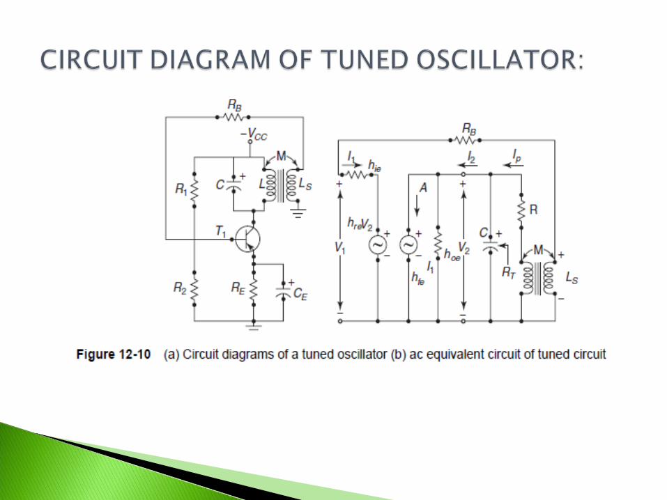

The circuit diagram of a tuned oscillator is shown in Fig. 12-10(a). The emitter by pass capacitor CE shunts the ac so that RE is omitted from the ac equivalent circuit of Fig. 12-10(b).
The dc operating point of the transistor is determined by the resistances R1, R2 and RE, and supply voltage. The transistor gives a phase-shift of 1800.
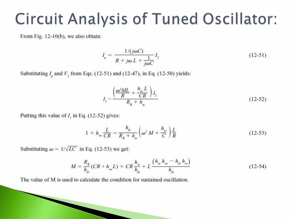
Circuit Analysis of Tuned Oscillator:

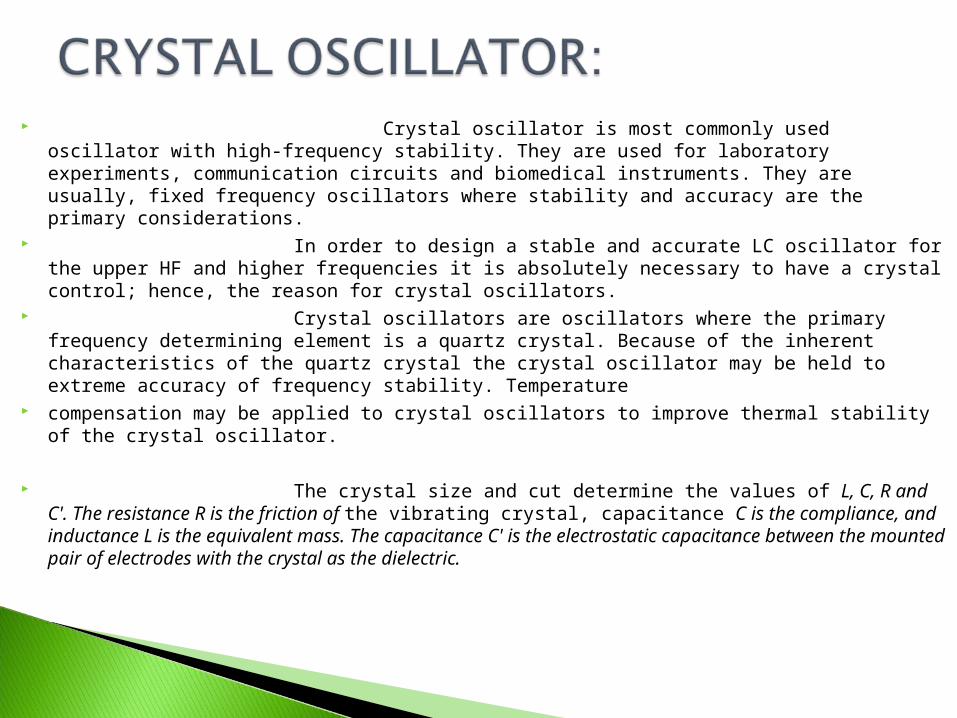
Crystal oscillator is most commonly used oscillator with high-frequency stability. They are used for laboratory experiments, communication circuits and biomedical instruments. They are usually, fixed frequency oscillators where stability and accuracy are the primary considerations.
In order to design a stable and accurate LC oscillator for the upper HF and higher frequencies it is absolutely necessary to have a crystal control; hence, the reason for crystal oscillators.
Crystal oscillators are oscillators where the primary frequency determining element is a quartz crystal. Because of the inherent characteristics of the quartz crystal the crystal oscillator may be held to extreme accuracy of frequency stability. Temperature
compensation may be applied to crystal oscillators to improve thermal stability of the crystal oscillator.
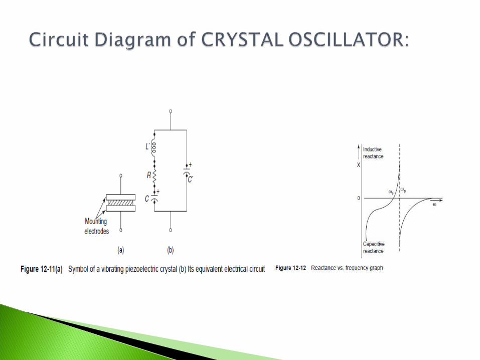
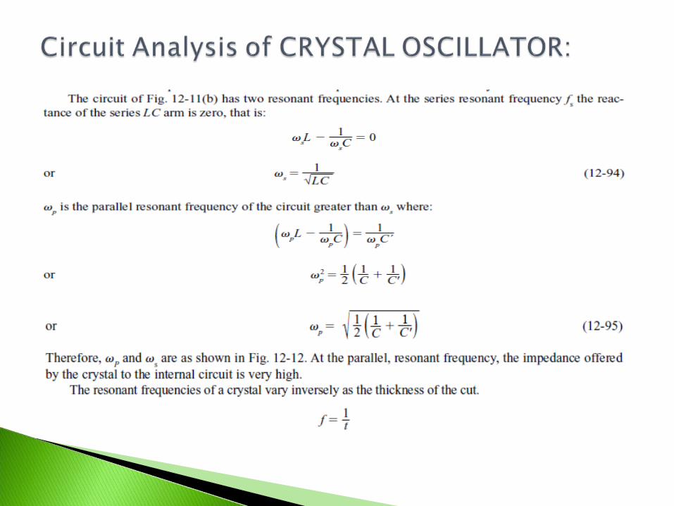
The crystal size and cut determine the values of L, C, R and C'. The resistance R
is the friction of the vibrating crystal, capacitance C is the compliance, and inductance L is the equivalent mass. The capacitance C' is the electrostatic capacitance between the mounted pair of electrodes with the crystal as the dielectric.


Oscillators are a common element of almost all electronic circuits. They are used in various applications, and their use makes it possible for circuits and subsystems to perform numerous useful functions.
In oscillator circuits, oscillation usually builds up from zero when power is first applied under linear circuit operation.
The oscillator’s amplitude is kept from building up by limiting the amplifier saturation and various non-linear effects.
Oscillator design and simulation is a complicated process. It is also extremely important and crucial to design a good and stable oscillator.
Oscillators are commonly used in communication circuits. All the communication circuits for different modulation techniques—AM, FM, PM—
the use of an oscillator is must. Oscillators are used as stable frequency sources in a variety of
electronic applications. Oscillator circuits are used in computer peripherals, counters,
timers, calculators, phase-locked loops, digital multi-metres, oscilloscopes, and numerous other applications.

A common oscillator implementation is the voltage-controlled oscillator (VCO) circuit, where an input tuning voltage is applied to an oscillator circuit and the tuning voltage adjusted to set the frequency at which the circuit oscillates.
The VCO is the most widely used oscillator circuit and it produces an oscillatory output voltage.
It provides a periodic signal, where the frequency of the periodic signal is related to the level of an input voltage control signal supplied to the VCO.
A VCO is simply an oscillator having a frequency output that is proportional to an applied voltage.
The centre frequency of a VCO is the frequency of the periodic output signal formed by the VCO when the input
control voltage is set to a nominal level.
The cascode crystal oscillator is composed of a Colpitts crystal oscillator and a base-common buffer amplifier in mobile circuits.
In the cascode crystal oscillator, a temparature-independent voltage source biases the buffer amplifier and the bypass capaciter gets eliminated.
GSM phones, set-top boxes and digital audio broadcasting equipments use oscillators. and digital audio roadcasting equipment use oscillators.

1. Oscillator converts dc to ac. 2. Oscillator has no input signal. 3. Oscillator behaviour is opposite to that of a rectifier. 4. The conditions and frequencies of oscillation are classified as:
