orthodontic bracket bonding from a different angle - an ... · orthodontics over the past couple of...
TRANSCRIPT
Abstract— Bracket bonding has become routine procedure in fixed
orthodontics over the past couple of decades. The choice whether to
receive ceramic or polycarbonate brackets is mainly the patient’s but
the issues related to bonding them are part of the practitioner’s
responsibility. Recurrent bracket debonding can unduly prolong
treatment or even lead to compromised results. Therefore, we
collected human extracted premolars and bonded them with
aesthetic brackets and investigated them by a new, non-invasive
method – optical coherence tomography (OCT) in order to assess the
quality of the bracket-tooth interface. The OCT investigation
revealed a series of gaps within the adhesive at the bracket-tooth
interface. The importance of our research resides in the fact that this
type of investigates opens a totally new perspective in dentistry due
to the fact that samples are left intact and ready for further testing
unlike of the majority of investigation methods available nowadays.
Keywords — optical coherence tomography, orthodontic
bonding, orthodontic brackets, non-invasive investigations. adhesive
dentistry
I. INTRODUCTION
Bracket bonding has become routine procedure in fixed
orthodontics over the past couple of decades. In spite that in
this field the requirements are not as high as in other
branches of adhesive dentistry, since the life span of a fixed
appliance is about 24 months, so shorter than that of a
prostheses, we still encounter problems, especially when
using tooth colored brackets. The choice whether to receive
ceramic or polycarbonate brackets is mainly the patient’s but
the issues related to bonding them are part of the
Manuscript received October 9, 2007: Revised version received August 7,
2011. This work was supported in part by the CNCSIS Grant TE 101/2010
Roxana Romînu is with the ―Victor Babes‖ University of Medicine and
Pharmacy Timişoara, School of Dentistry, Department of Prostheses Technology
and Dental Materials, Bd. Revolutiei Nr. 9, Timisoara Romania,
Cosmin Sinescu is with the ―Victor Babes‖ University of Medicine and
Pharmacy Timişoara, School of Dentistry, Department of Prostheses Technology
and Dental Materials, Bd. Revolutiei Nr. 9, Timisoara Romania
Meda Negrutiu is with the ―Victor Babes‖ University of Medicine and
Pharmacy Timişoara, School of Dentistry, Department of Prostheses Technology
and Dental Materials, Bd. Revolutiei Nr. 9, Timisoara Romania
practitioner’s responsibility. Recurrent bracket debonding can
unduly prolong treatment or even lead to compromised
results.
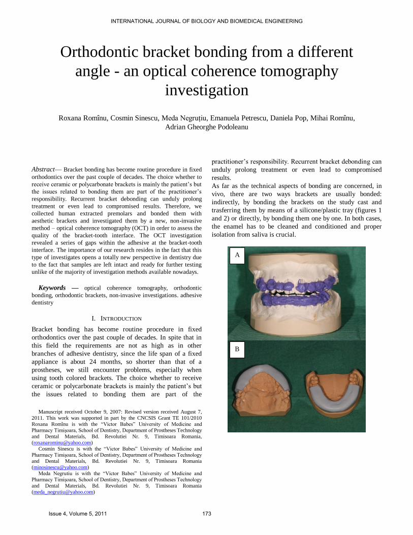
As far as the technical aspects of bonding are concerned, in
vivo, there are two ways brackets are usually bonded:
indirectly, by bonding the brackets on the study cast and
trasferring them by means of a silicone/plastic tray (figures 1
and 2) or directly, by bonding them one by one. In both cases,
the enamel has to be cleaned and conditioned and proper
isolation from saliva is crucial.
Orthodontic bracket bonding from a different
angle - an optical coherence tomography
investigation
Roxana Romînu, Cosmin Sinescu, Meda Negruţiu, Emanuela Petrescu, Daniela Pop, Mihai Romînu,
Adrian Gheorghe Podoleanu
A
B
INTERNATIONAL JOURNAL OF BIOLOGY AND BIOMEDICAL ENGINEERING
Issue 4, Volume 5, 2011 173
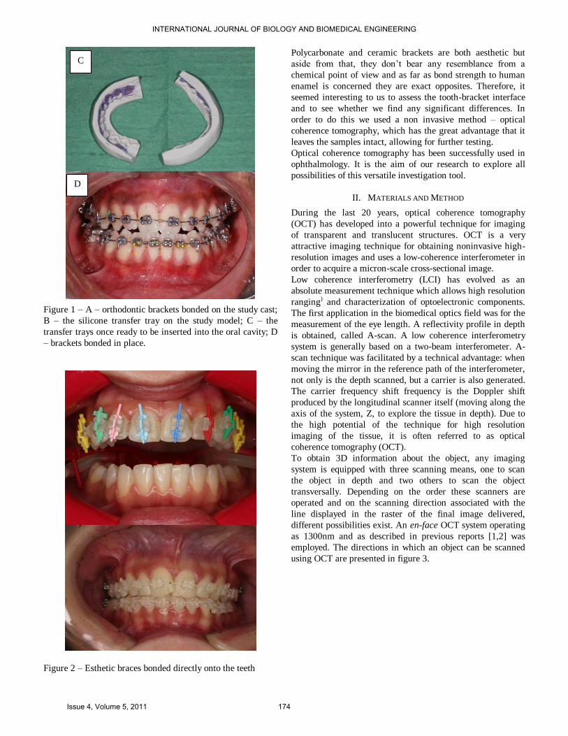
Figure 1 – A – orthodontic brackets bonded on the study cast;
B – the silicone transfer tray on the study model; C – the
transfer trays once ready to be inserted into the oral cavity; D
– brackets bonded in place.
Figure 2 – Esthetic braces bonded directly onto the teeth
Polycarbonate and ceramic brackets are both aesthetic but
aside from that, they don’t bear any resemblance from a
chemical point of view and as far as bond strength to human
enamel is concerned they are exact opposites. Therefore, it
seemed interesting to us to assess the tooth-bracket interface
and to see whether we find any significant differences. In
order to do this we used a non invasive method – optical
coherence tomography, which has the great advantage that it
leaves the samples intact, allowing for further testing.
Optical coherence tomography has been successfully used in
ophthalmology. It is the aim of our research to explore all
possibilities of this versatile investigation tool.
II. MATERIALS AND METHOD
During the last 20 years, optical coherence tomography
(OCT) has developed into a powerful technique for imaging
of transparent and translucent structures. OCT is a very
attractive imaging technique for obtaining noninvasive high-
resolution images and uses a low-coherence interferometer in
order to acquire a micron-scale cross-sectional image.
Low coherence interferometry (LCI) has evolved as an
absolute measurement technique which allows high resolution
ranging) and characterization of optoelectronic components.
The first application in the biomedical optics field was for the
measurement of the eye length. A reflectivity profile in depth
is obtained, called A-scan. A low coherence interferometry
system is generally based on a two-beam interferometer. A-
scan technique was facilitated by a technical advantage: when
moving the mirror in the reference path of the interferometer,
not only is the depth scanned, but a carrier is also generated.
The carrier frequency shift frequency is the Doppler shift
produced by the longitudinal scanner itself (moving along the
axis of the system, Z, to explore the tissue in depth). Due to
the high potential of the technique for high resolution
imaging of the tissue, it is often referred to as optical
coherence tomography (OCT).
To obtain 3D information about the object, any imaging
system is equipped with three scanning means, one to scan
the object in depth and two others to scan the object
transversally. Depending on the order these scanners are
operated and on the scanning direction associated with the
line displayed in the raster of the final image delivered,
different possibilities exist. An en-face OCT system operating
as 1300nm and as described in previous reports [1,2] was
employed. The directions in which an object can be scanned
using OCT are presented in figure 3.
C
D
INTERNATIONAL JOURNAL OF BIOLOGY AND BIOMEDICAL ENGINEERING
Issue 4, Volume 5, 2011 174
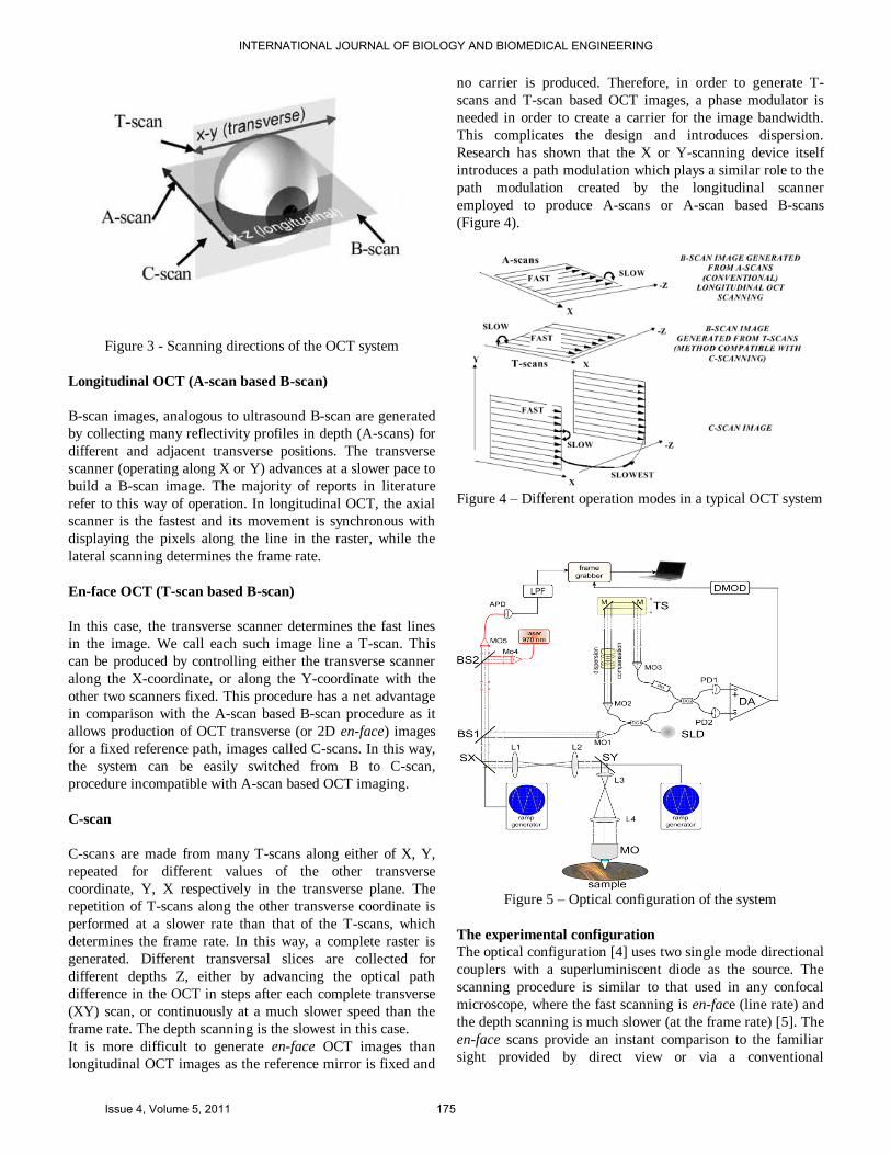
Figure 3 - Scanning directions of the OCT system
Longitudinal OCT (A-scan based B-scan)
B-scan images, analogous to ultrasound B-scan are generated
by collecting many reflectivity profiles in depth (A-scans) for
different and adjacent transverse positions. The transverse
scanner (operating along X or Y) advances at a slower pace to
build a B-scan image. The majority of reports in literature
refer to this way of operation. In longitudinal OCT, the axial
scanner is the fastest and its movement is synchronous with
displaying the pixels along the line in the raster, while the
lateral scanning determines the frame rate.
En-face OCT (T-scan based B-scan)
In this case, the transverse scanner determines the fast lines
in the image. We call each such image line a T-scan. This
can be produced by controlling either the transverse scanner
along the X-coordinate, or along the Y-coordinate with the
other two scanners fixed. This procedure has a net advantage
in comparison with the A-scan based B-scan procedure as it
allows production of OCT transverse (or 2D en-face) images
for a fixed reference path, images called C-scans. In this way,
the system can be easily switched from B to C-scan,
procedure incompatible with A-scan based OCT imaging.
C-scan
C-scans are made from many T-scans along either of X, Y,
repeated for different values of the other transverse
coordinate, Y, X respectively in the transverse plane. The
repetition of T-scans along the other transverse coordinate is
performed at a slower rate than that of the T-scans, which
determines the frame rate. In this way, a complete raster is
generated. Different transversal slices are collected for
different depths Z, either by advancing the optical path
difference in the OCT in steps after each complete transverse
(XY) scan, or continuously at a much slower speed than the
frame rate. The depth scanning is the slowest in this case.
It is more difficult to generate en-face OCT images than
longitudinal OCT images as the reference mirror is fixed and
no carrier is produced. Therefore, in order to generate T-
scans and T-scan based OCT images, a phase modulator is
needed in order to create a carrier for the image bandwidth.
This complicates the design and introduces dispersion.
Research has shown that the X or Y-scanning device itself
introduces a path modulation which plays a similar role to the
path modulation created by the longitudinal scanner
employed to produce A-scans or A-scan based B-scans
(Figure 4).
Figure 4 – Different operation modes in a typical OCT system
Figure 5 – Optical configuration of the system
The experimental configuration
The optical configuration [4] uses two single mode directional
couplers with a superluminiscent diode as the source. The
scanning procedure is similar to that used in any confocal
microscope, where the fast scanning is en-face (line rate) and
the depth scanning is much slower (at the frame rate) [5]. The
en-face scans provide an instant comparison to the familiar
sight provided by direct view or via a conventional
INTERNATIONAL JOURNAL OF BIOLOGY AND BIOMEDICAL ENGINEERING
Issue 4, Volume 5, 2011 175
microscope [6]. Features seen with the naked eye could easily
be compared with features hidden in depth. Sequential and
rapid switching between the en-face regime and the cross-
section regime, specific for the en-face OCT systems
developed by us, represents a significant advantage in the
non-invasive imaging. Images with different orientations can
be obtained using the same system. As shown in figure 4, in
the en-face regime, the frame grabber is controlled by signals
from the generators driving the X-scanner and the Y-scanner.
One galvo-scanner is driven with a ramp at 500 Hz and the
other galvo-scanner with a ramp at 2 Hz. In this way, an en-
face image, in the plane (x, y) is generated at constant depth.
The next en-face image at a new depth is then generated by
moving the translation stage in the reference arm of the
interferometer and repeating the (x, y) scan. Ideally, the depth
interval between successive frames should be much smaller
than the system resolution in depth and the depth change
applied only after the entire en-face image has been collected.
However, in practice, to speed up the acquisition, the
translation stage was moved continuously. Alternatively, a
scanning delay line could be used, which can achieve faster
depth scanning rates [7]. In the images presented below, no
other phase modulation was employed apart from that
introduced by the X-galvanometer scanner [8]. In Podoleanu
et al [9], we demonstrated the role played by the image size in
balancing the effects of an external phase modulator and of
the modulation produced by the transversal scanner. If the
image is sufficient large, then the distortions introduced by
not using a phase modulator are insignificant.
In the cross-section regime, the frame grabber is controlled by
signals from the generator driving the X-scanner (or the Y-
scanner) with a ramp at 500 Hz and the translation stage
moving over the depth range required in 0.5 s. In this case, an
OCT cross-section image is produced either in the plane (x,
z) or (y, z).
In the images presented below, no other phase modulation
was employed apart from that introduced by the X
galvanometer scanner, determining the line in the raster. We
demonstrated in a previous study the role played by the image
size in balancing the effects of an external phase modulator
and of the modulation produced by the transversal scanner. If
the image is sufficient large, then the distortions introduced
by not using a phase modulator are insignificant.
The system operates together with a confocal microscope at a
wavelength of 970 nm. This allows for the easy identification
of the area of interest which can then be scanned using the
OCT. Confocal microscopy can detect superficial defects
itself, whereas the OCT is required to identify the deeper
material defects (Figure 5). The confocal channel operates at
a different wavelength than that of the OCT, to allow the
utilization of a high gain silicon avalanche photodiode, APD.
Light from a superluminescent diode at 970 nm is collimated
by a microscope objective MO4 and reflected by a splitter BS2
(20% reflection) towards BS1. Light at 970 nm is transmitted
via BS1 and BS2 towards the APD. The photo-detected signal
is amplified and low pass filtered in LPF.
Sample processing and evaluation
We collected 40 crack-free, non carious extracted human first
premolars and third molars. All teeth were stored in tap water
at 4 ºC until they were used. In order to create the samples the
teeth were professionally cleaned with pumice and rotary
brushes by a single operator. In order to eliminate possible
flaws the rotary brush was changed for a new one after every
fifth tooth. After cleaning the teeth were thoroughly rinsed
and dried and divided into two groups of 20 teeth each and
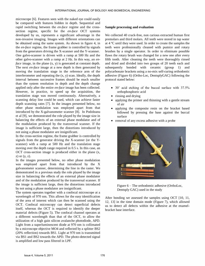
subsequently bonded with ceramic (group 1) and
polycarbonate brackets using a no-mix self-curing orthodontic
adhesive (Figure 6) (Ortho-Loc, DentsplyGAC) following the
protocol stated below:
30’ acid etching of the buccal surface with 37.5%
orthophosphoric acid
rinsing and drying
applying the primer and thinning with a gentle stream
of air
applying the composite resin on the bracket based
followed by pressing the base against the buccal
surface
removal of any excess adhesive with a probe
Figure 6 – The orthodontic adhesive (OrthoLoc,
Dentsply GAC) used in the study
After bonding we assessed the samples using OCT [10, 11,
12, 13] in the time domain mode (Figure 7), which allowed
us to detect all defects within the adhesive at the enamel-
bracket base interface.
INTERNATIONAL JOURNAL OF BIOLOGY AND BIOMEDICAL ENGINEERING
Issue 4, Volume 5, 2011 176
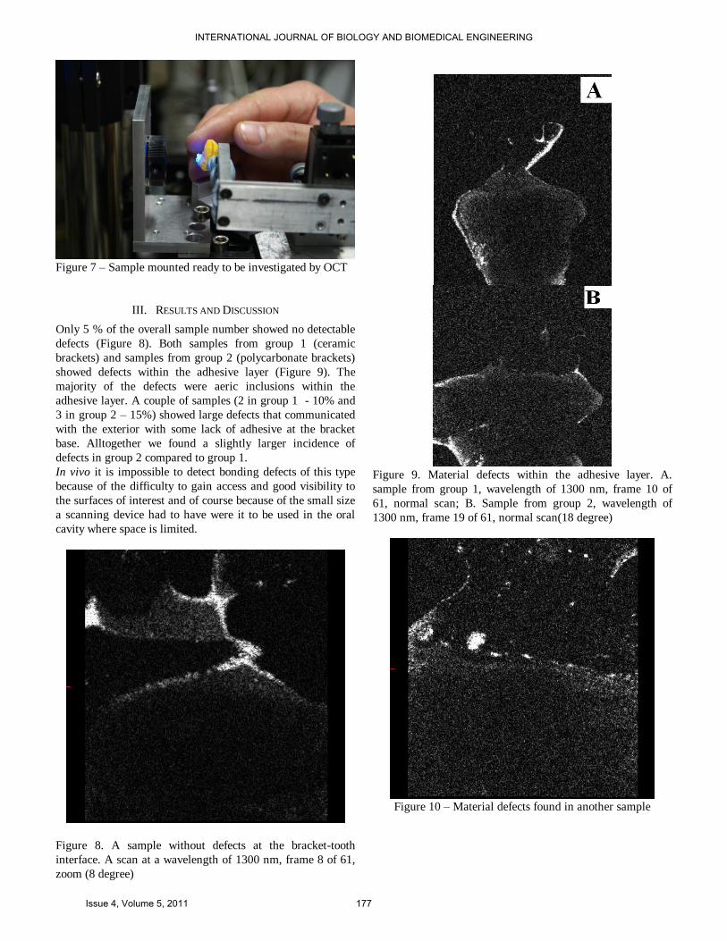
Figure 7 – Sample mounted ready to be investigated by OCT
III. RESULTS AND DISCUSSION
Only 5 % of the overall sample number showed no detectable
defects (Figure 8). Both samples from group 1 (ceramic
brackets) and samples from group 2 (polycarbonate brackets)
showed defects within the adhesive layer (Figure 9). The
majority of the defects were aeric inclusions within the
adhesive layer. A couple of samples (2 in group 1 - 10% and
3 in group 2 – 15%) showed large defects that communicated
with the exterior with some lack of adhesive at the bracket
base. Alltogether we found a slightly larger incidence of
defects in group 2 compared to group 1.
In vivo it is impossible to detect bonding defects of this type
because of the difficulty to gain access and good visibility to
the surfaces of interest and of course because of the small size
a scanning device had to have were it to be used in the oral
cavity where space is limited.
Figure 8. A sample without defects at the bracket-tooth
interface. A scan at a wavelength of 1300 nm, frame 8 of 61,
zoom (8 degree)
Figure 9. Material defects within the adhesive layer. A.
sample from group 1, wavelength of 1300 nm, frame 10 of
61, normal scan; B. Sample from group 2, wavelength of
1300 nm, frame 19 of 61, normal scan(18 degree)
Figure 10 – Material defects found in another sample
INTERNATIONAL JOURNAL OF BIOLOGY AND BIOMEDICAL ENGINEERING
Issue 4, Volume 5, 2011 177
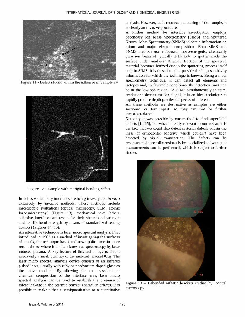
Figure 11 - Defects found within the adhesive in Sample 24
Figure 12 – Sample with mariginal bonding defect
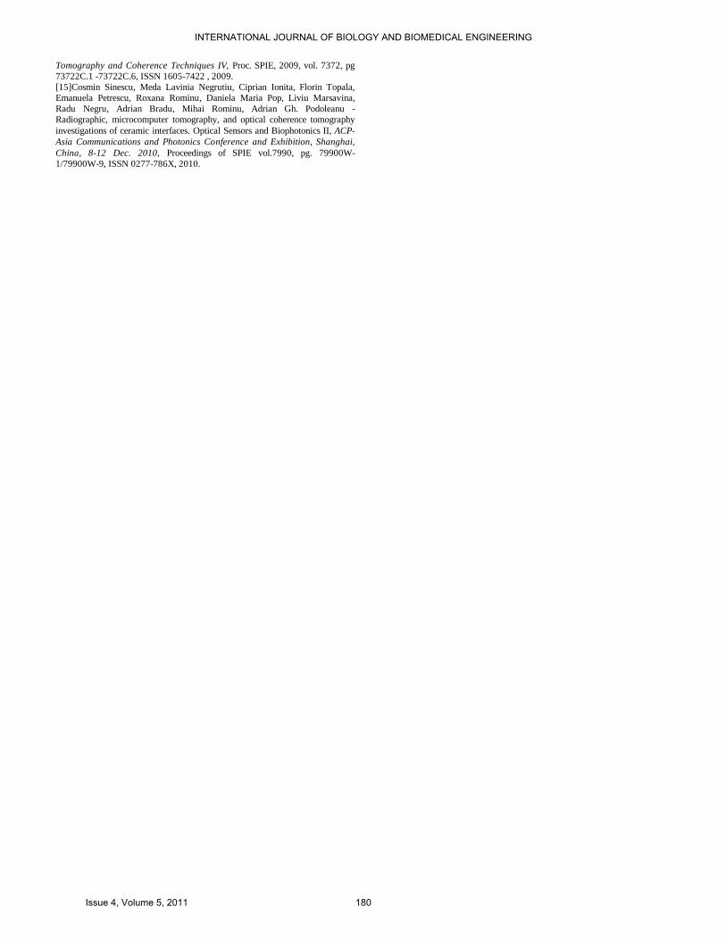
In adhesive dentistry interfaces are being investigated in vitro
exlusively by invasive methods. These methods include
microscopic evaluations (optical microscopy, SEM, atomic
force microscopy ) (Figure 13), mechanical tests (where
adhesive interfaces are tested for their shear bond strength
and tensile bond strength by means of standardized testing
devices) (Figures 14, 15).
An alternative technique is laser micro spectral analysis. First
introduced in 1962 as a method of investigating the surfaces
of metals, the technique has found new applications in more
recent times, where it is often known as spectroscopy by laser
induced plasma. A key feature of this technology is that it
needs only a small quantity of the material, around 0.1g. The
laser micro spectral analysis device consists of an infrared
pulsed laser, usually with ruby or neodymium doped glass as
the active medium. By allowing for an assessment of
chemical composition of the interface area, laser micro
spectral analysis can be used to establish the presence of
micro leakage in the ceramic bracket enamel interfaces. It is
possible to make either a semiquantitative or a quantitative
analysis. However, as it requires puncturing of the sample, it
is clearly an invasive procedure.
A further method for interface investigation employs
Secondary Ion Mass Spectrometry (SIMS) and Sputtered
Neutral Mass Spectrometry (SNMS) to obtain information on
minor and major element composition. Both SIMS and
SNMS methods use a focused, mono-energetic, chemically
pure ion beam of typically 1-10 keV to sputter erode the
surface under analysis. A small fraction of the sputtered
material becomes ionized due to the sputtering process itself
and, in SIMS, it is these ions that provide the high-sensitivity
information for which the technique is known. Being a mass
spectrometry technique, it can detect all elements and
isotopes and, in favorable conditions, the detection limit can
be in the low ppb region. As SIMS simultaneously sputters,
erodes and detects the ion signal, it is an ideal technique to
rapidly produce depth profiles of species of interest.
All these methods are destructive as samples are either
sectioned or torn apart, so they can not be further
investigated/used.
Not only it was possible by our method to find superficial
defects [14,15], but what is really relevant to our research is
the fact that we could also detect material defects within the
mass of orthodontic adhesive which couldn’t have been
detected by visual examination. The defects can be
reconstructed three-dimensionally by specialized software and
measurements can be performed, which is subject to further
studies.
Figure 13 – Debonded esthetic brackets studied by optical
microscopy
INTERNATIONAL JOURNAL OF BIOLOGY AND BIOMEDICAL ENGINEERING
Issue 4, Volume 5, 2011 178
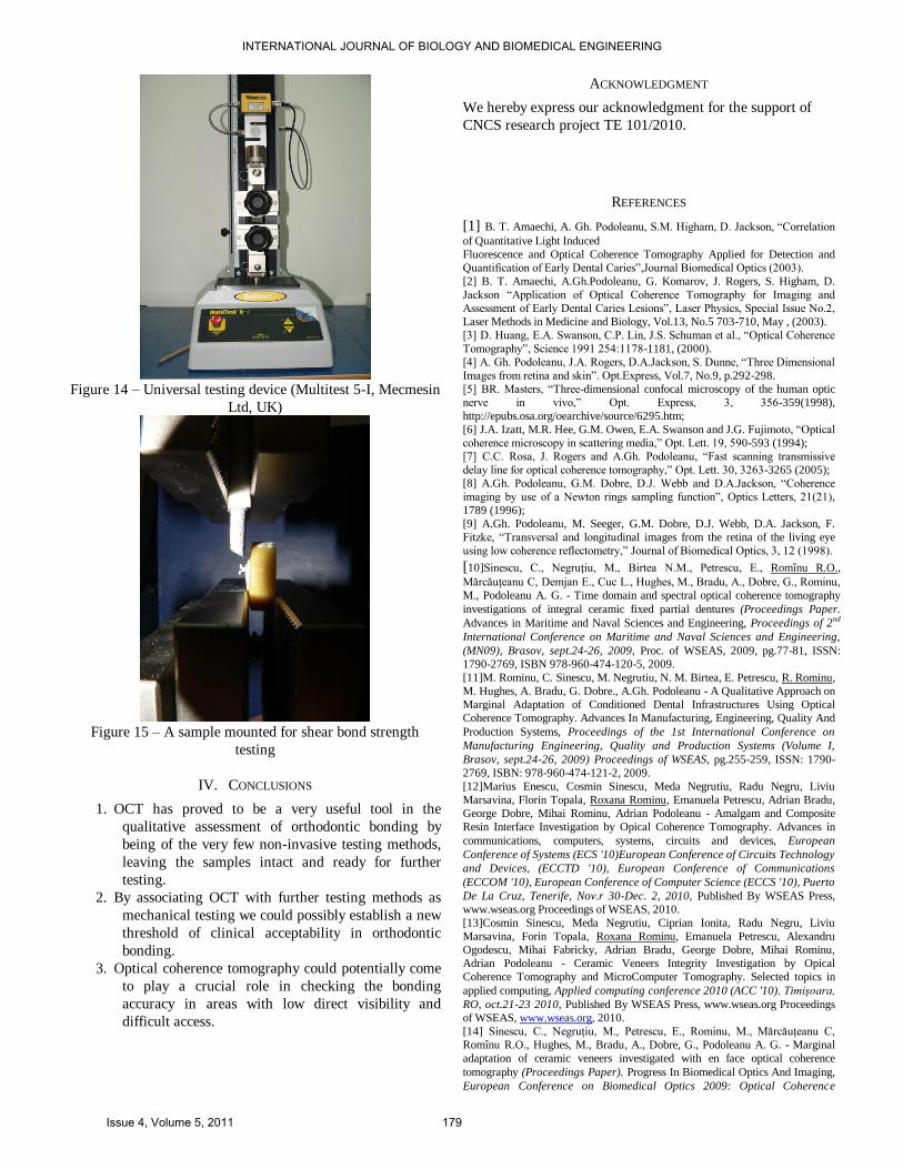
Figure 14 – Universal testing device (Multitest 5-I, Mecmesin
Ltd, UK)
Figure 15 – A sample mounted for shear bond strength
testing
IV. CONCLUSIONS
1. OCT has proved to be a very useful tool in the
qualitative assessment of orthodontic bonding by
being of the very few non-invasive testing methods,
leaving the samples intact and ready for further
testing.
2. By associating OCT with further testing methods as
mechanical testing we could possibly establish a new
threshold of clinical acceptability in orthodontic
bonding.
3. Optical coherence tomography could potentially come
to play a crucial role in checking the bonding
accuracy in areas with low direct visibility and
difficult access.
ACKNOWLEDGMENT
We hereby express our acknowledgment for the support of
CNCS research project TE 101/2010.
REFERENCES
[1] B. T. Amaechi, A. Gh. Podoleanu, S.M. Higham, D. Jackson, ―Correlation
of Quantitative Light Induced
Fluorescence and Optical Coherence Tomography Applied for Detection and
Quantification of Early Dental Caries‖,Journal Biomedical Optics (2003).
[2] B. T. Amaechi, A.Gh.Podoleanu, G. Komarov, J. Rogers, S. Higham, D.
Jackson ―Application of Optical Coherence Tomography for Imaging and
Assessment of Early Dental Caries Lesions‖, Laser Physics, Special Issue No.2,
Laser Methods in Medicine and Biology, Vol.13, No.5 703-710, May , (2003).
[3] D. Huang, E.A. Swanson, C.P. Lin, J.S. Schuman et al., ―Optical Coherence
Tomography‖, Science 1991 254:1178-1181, (2000).
[4] A. Gh. Podoleanu, J.A. Rogers, D.A.Jackson, S. Dunne, ―Three Dimensional
Images from retina and skin‖. Opt.Express, Vol.7, No.9, p.292-298.
[5] BR. Masters, ―Three-dimensional confocal microscopy of the human optic
nerve in vivo,‖ Opt. Express, 3, 356-359(1998),
http://epubs.osa.org/oearchive/source/6295.htm;
[6] J.A. Izatt, M.R. Hee, G.M. Owen, E.A. Swanson and J.G. Fujimoto, ―Optical
coherence microscopy in scattering media,‖ Opt. Lett. 19, 590-593 (1994);
[7] C.C. Rosa, J. Rogers and A.Gh. Podoleanu, ―Fast scanning transmissive
delay line for optical coherence tomography,‖ Opt. Lett. 30, 3263-3265 (2005);
[8] A.Gh. Podoleanu, G.M. Dobre, D.J. Webb and D.A.Jackson, ―Coherence
imaging by use of a Newton rings sampling function‖, Optics Letters, 21(21),
1789 (1996);
[9] A.Gh. Podoleanu, M. Seeger, G.M. Dobre, D.J. Webb, D.A. Jackson, F.
Fitzke, ―Transversal and longitudinal images from the retina of the living eye
using low coherence reflectometry,‖ Journal of Biomedical Optics, 3, 12 (1998).
[10]Sinescu, C., Negruţiu, M., Birtea N.M., Petrescu, E., Romînu R.O.,
Mărcăuţeanu C, Demjan E., Cuc L., Hughes, M., Bradu, A., Dobre, G., Rominu,
M., Podoleanu A. G. - Time domain and spectral optical coherence tomography
investigations of integral ceramic fixed partial dentures (Proceedings Paper.
Advances in Maritime and Naval Sciences and Engineering, Proceedings of 2nd
International Conference on Maritime and Naval Sciences and Engineering,
(MN09), Brasov, sept.24-26, 2009, Proc. of WSEAS, 2009, pg.77-81, ISSN:
1790-2769, ISBN 978-960-474-120-5, 2009.
[11]M. Rominu, C. Sinescu, M. Negrutiu, N. M. Birtea, E. Petrescu, R. Rominu,
M. Hughes, A. Bradu, G. Dobre., A.Gh. Podoleanu - A Qualitative Approach on
Marginal Adaptation of Conditioned Dental Infrastructures Using Optical
Coherence Tomography. Advances In Manufacturing, Engineering, Quality And
Production Systems, Proceedings of the 1st International Conference on
Manufacturing Engineering, Quality and Production Systems (Volume I,
Brasov, sept.24-26, 2009) Proceedings of WSEAS, pg.255-259, ISSN: 1790-
2769, ISBN: 978-960-474-121-2, 2009.
[12]Marius Enescu, Cosmin Sinescu, Meda Negrutiu, Radu Negru, Liviu
Marsavina, Florin Topala, Roxana Rominu, Emanuela Petrescu, Adrian Bradu,
George Dobre, Mihai Rominu, Adrian Podoleanu - Amalgam and Composite
Resin Interface Investigation by Opical Coherence Tomography. Advances in
communications, computers, systems, circuits and devices, European
Conference of Systems (ECS '10)European Conference of Circuits Technology
and Devices, (ECCTD '10), European Conference of Communications
(ECCOM '10), European Conference of Computer Science (ECCS '10), Puerto
De La Cruz, Tenerife, Nov.r 30-Dec. 2, 2010, Published By WSEAS Press,
www.wseas.org Proceedings of WSEAS, 2010.
[13]Cosmin Sinescu, Meda Negrutiu, Ciprian Ionita, Radu Negru, Liviu
Marsavina, Forin Topala, Roxana Rominu, Emanuela Petrescu, Alexandru
Ogodescu, Mihai Fabricky, Adrian Bradu, George Dobre, Mihai Rominu,
Adrian Podoleanu - Ceramic Veneers Integrity Investigation by Opical
Coherence Tomography and MicroComputer Tomography. Selected topics in
applied computing, Applied computing conference 2010 (ACC '10), Timişoara,
RO, oct.21-23 2010, Published By WSEAS Press, www.wseas.org Proceedings
of WSEAS, www.wseas.org, 2010.
[14] Sinescu, C., Negruţiu, M., Petrescu, E., Rominu, M., Mărcăuţeanu C,
Romînu R.O., Hughes, M., Bradu, A., Dobre, G., Podoleanu A. G. - Marginal
adaptation of ceramic veneers investigated with en face optical coherence
tomography (Proceedings Paper). Progress In Biomedical Optics And Imaging,
European Conference on Biomedical Optics 2009: Optical Coherence
INTERNATIONAL JOURNAL OF BIOLOGY AND BIOMEDICAL ENGINEERING
Issue 4, Volume 5, 2011 179
Tomography and Coherence Techniques IV, Proc. SPIE, 2009, vol. 7372, pg
73722C.1 -73722C.6, ISSN 1605-7422 , 2009.
[15]Cosmin Sinescu, Meda Lavinia Negrutiu, Ciprian Ionita, Florin Topala,
Emanuela Petrescu, Roxana Rominu, Daniela Maria Pop, Liviu Marsavina,
Radu Negru, Adrian Bradu, Mihai Rominu, Adrian Gh. Podoleanu -
Radiographic, microcomputer tomography, and optical coherence tomography
investigations of ceramic interfaces. Optical Sensors and Biophotonics II, ACP-
Asia Communications and Photonics Conference and Exhibition, Shanghai,
China, 8-12 Dec. 2010, Proceedings of SPIE vol.7990, pg. 79900W-
1/79900W-9, ISSN 0277-786X, 2010.
INTERNATIONAL JOURNAL OF BIOLOGY AND BIOMEDICAL ENGINEERING
Issue 4, Volume 5, 2011 180