orkney research centre for archaeology orca …€¦ · orkney research centre for archaeology –...
TRANSCRIPT

Orkney Research Centre for Archaeology – ORCA Marine
Roan Head, Flotta
Roan Head Boom Buoy Vessel
Project Report
March 2015
Diving Survey: Boom Buoy Vessel Side scan: Boom Buoy Vessel

Orkney Research Centre for Archaeology – ORCA Marine
This page is deliberately blank

Orkney Research Centre for Archaeology – ORCA Marine
Title: Roan Head Boom Buoy Vessel: Project Report
Author(s): Annalisa Christie, Marine Archaeologist ORCA Marine,
[email protected]; 01856 569346
Kevin Heath, Marine Historian, SULA Diving, [email protected];
01856 850285
Mark Littlewood, Geomatics Officer, ORCA Marine,
[email protected]; 01856 569227
Derivation:
Origination Date: 12 March 2015
Reviser(s): Paul Sharman, Philip Robertson, Annalisa Christie, Kevin Heath
Date of last
revision:
19 March 2015
Version: V3
Status: Final Report
Summary of
Changes:
Circulation: Philip Robertson, Historic Scotland,
Required Action:
File Name /
Location:
X:\MarineArchaeology\ORCA Marine
Projects\572_HS_Boom_Buoys\Report\572_Boom_Buoy_Barge
_Report_Final
Approval:

Orkney Research Centre for Archaeology – ORCA Marine
This page is deliberately blank

Orkney Research Centre for Archaeology – ORCA Marine
CONTENTS
Table of Plates ........................................................................................................... 6
Table of Figures ......................................................................................................... 6
Executive Summary ................................................................................................... 7
Acknowledgements .................................................................................................... 7
1. Introduction ......................................................................................................... 1
2. Project Background ............................................................................................. 1
3. Aims and Objectives ........................................................................................... 2
4. Methodology ....................................................................................................... 2
4.1 Desk Based Assessment Data Sources ........................................................ 2
4.2 GIS ................................................................................................................ 3
4.3 Side Scan Sonar Survey ............................................................................... 3
4.4 Side Scan Data Processing........................................................................... 4
4.5 Diver Ground-truthing .................................................................................... 4
5. Results ................................................................................................................ 5
5.1 Side scan sonar survey ................................................................................. 5
5.1.1 Target site (Canmore ID 102201) ........................................................... 5
5.1.2 Other key side scan sonar contacts ........................................................ 7
5.2 Diving surveys ............................................................................................... 9
6. Discussion ......................................................................................................... 13
6.1 Identification ................................................................................................ 13
6.2 Construction and Use .................................................................................. 15
6.3 Other known ATCPP sites .......................................................................... 18
6.3.1 Roan Head, Flotta (Canmore ID 249683) ............................................. 18
6.3.2 Hoxa Head (Canmore ID 314006) ........................................................ 20
7. Conclusions and Future Work ........................................................................... 22
8. Bibliography ...................................................................................................... 24

Orkney Research Centre for Archaeology – ORCA Marine
TABLE OF PLATES
Note plates of side scan sonar images do not include scale or orientation. For scale
an orientation see Figures.
Plate 1: Side scan sonar image of the target site (RC1 and RC2) ............................. 5
Plate 2: Side scan sonar image of associated boom defence debris ......................... 6
Plate 3: Photograph of Spar C ................................................................................... 7
Plate 4: Side scan sonar Image of RC3 ..................................................................... 7
Plate 5: Side scan sonar image of RC4, RC5 and CC1. ............................................ 8
Plate 6: Photographs of vessel machinery ............................................................... 10
Plate 7: Photographs of Tread-plate......................................................................... 10
Plate 8: Photographs of boom buoys and netting ..................................................... 11
Plate 9: RC2 Boom Netting ...................................................................................... 11
Plate 10: RC2 Winch and Moon-pool ....................................................................... 12
Plate 11: Examples of spars ..................................................................................... 13
Plate 12: Evidence of wooden rubbing strip ............................................................. 15
Plate 13: Join between two sections of the pontoon ................................................ 15
Plate 14: Alignment of winch on pontoons deployed from Rosyth (ADM244-26). .... 16
Plate 15: Pontoons in operation protecting HMS Duke of York in the Firth of Forth
(ADM 224/26) ........................................................................................................... 17
Plate 16: Remains of a Pontoon on Roan Head, Flotta ............................................ 18
Plate 17: Evidence of burning indicating salvage of machinery ................................ 19
Plate 18: Examples of Features on the Flotta barge replicated underwater ............. 19
Plate 19: Distribution of pontoon wreckage at Hoxa ................................................. 20
Plate 20: More intact portion of pontoon section at Hoxa ......................................... 21
Plate 21: Dispersed pontoon debris at Hoxa ............................................................ 21
TABLE OF FIGURES
Figure 1: Mosaic of side scan sonar survey runs showing distribution of observed features
At end
Figure 2: Side scan sonar and stills images of RC1 and RC2 At end Figure 3: Distribution of rectangular contacts in relation to moorings
detailed on historic chart. At end

Orkney Research Centre for Archaeology – ORCA Marine
EXECUTIVE SUMMARY
This report presents the outcomes of side scan sonar surveys and archaeological
diving evaluations of two boom defence vessels located off the north coast of Flotta
within Scapa Flow, Orkney (Canmore ID 102201). The site was initially dived by Rob
Baxandall off the MV Valkyrie in September 2014. He reported that the wreck was a
long narrow vessel that was associated with World War II boom defence debris
(boom netting and buoys) – which overlay and surrounded the site.
The remains were described to Kevin Heath and Annalisa Christie and following
discussions with Hazel Weaver (of the MV Valkyrie) a project was proposed to
Historic Scotland to conduct an assessment of the site and surrounding area to
confirm the identification, survival, character and condition of the remains.
Desk based assessment of archival sources, in light of diver surveys of the vessels,
indicate that these are the remains of experimental Anti-Torpedo Close Protection
Pontoons, used in the close protection of vessels at anchor from aircraft launch
torpedoes. The pontoons were only in operation for 13 months (March 1941 – April
1942) and few were brought into service – with the majority of the units deployed in
Scapa Flow and Rosyth. As such they represent a rare heritage resource for which
very little is known about their operation.
Side scan sonar surveys of the surrounding area resulted in the identification of
numerous features including three other rectangular contacts, which could represent
the remains of other pontoons. Further surveys of these sites using a Remote
Operated Vehicle (ROV) is recommended, to confirm the identity of the remains and
to further elucidate the configuration and operation of these vessels.
While it is not within the remit of this survey project to address management issues,
the evidence from this project (and the outcomes of previous surveys) should
contribute to HS and stakeholders formulating appropriate management and
monitoring strategies for heritage assets with Scapa Flow resource more broadly.
ACKNOWLEDGEMENTS
ORCA Marine would like to thank Rob Baxandall and Hazel Weaver for bringing the
remains to light. Had the site not been reported, a unique heritage asset would have
been overlooked and the identity of similar vessels on Flotta and at Hoxa would have
remained unconfirmed. We would also like to thank Philip Robertson for his
comments on early drafts of this report and his advice throughout the project. Finally,
thanks to UKHO for permission to use their charts.
Annalisa Christie, Kevin Heath and Mark Littlewood authored this report. In addition,
Malcolm Thomson and Brett Green completed the side scan sonar and diving
surveys, facilitating the data collection.

Orkney Research Centre for Archaeology – ORCA Marine
This page is deliberately blank

Orkney Research Centre for Archaeology – ORCA Marine
1 Project 572: Roan Head Boom Buoy Vessel - Project Report
1. INTRODUCTION
This report presents the outcomes of a project commissioned by Historic Scotland
(HS) to undertake an archaeological assessment of submerged wartime defences off
Roan Head, Flotta with particular reference to the reported remains of a vessel
indicated by the symbol Wk 19 on the chart (Canmore ID 102201). The wreck is
situated in an area of foul ground.
The site was initially dived by Rob Baxandall off the MV Valkyrie in September 2014.
He reported that the wreck was a long narrow vessel that was associated with World
War II boom defence debris (boom netting and buoys) – which overlay and
surrounded the site. It was hypothesised that the vessel could be the wreck of a
boom gate vessel which would have been used to deploy the boom nets and buoys.
The remains were described to Kevin Heath and Annalisa Christie and following
discussions with Hazel Weaver (of the MV Valkyrie) a project was proposed to
Historic Scotland to conduct an assessment of the site and surrounding area using
side scan sonar and diver ground truthing.
The surveys aimed to confirm the identification, survival, character and condition of
the remains in support of the HS Strategy for the protection, management and
promotion of marine heritage 2012 - 15. The strategy aims to help advance
knowledge, understanding and enjoyment of marine heritage, disseminating such
information widely and to improve stewardship of key marine heritage assets.
2. PROJECT BACKGROUND
The surveys undertaken build on the work of previous projects conducted in Scapa
Flow, which have provided baseline and monitoring data to document the extent and
condition of submerged heritage assets in the area. These projects include:
Multibeam Echosounder (MBES) surveys in 2001 and 2006 as part of the HS
funded ScapaMap project to map the remains of the scuttled German High
Seas Fleet and the area of the Royal Navy Anchorage including the
dispersed remains of the HMS Vanguard (http://www.scapamap.org);
Ministry of Defence (MoD) surveys of the HMS Royal Oak;
HS-funded MBES surveys completed by Wessex Archaeology (WA) in 2011
to map the blockships in Burra Sound and other wartime wrecks (HMS
Strathgarry; UB116; the F2 and YC21 barge; S54; V83; and Dewey Eve)
(Dresch and McCarthy 2012);
Desk-based assessment (DBA) work to improve the record of the marine
historic environment conducted as part of HS and the Royal Commission for
Ancient and Historic Monuments of Scotland (RCAHMS) Project Adair
(Pollard et al. 2012); and

Orkney Research Centre for Archaeology – ORCA Marine
2 Project 572: Roan Head Boom Buoy Vessel - Project Report
Side scan sonar and diving surveys of the blockships at the Churchill Barriers
and lesser known wartime wrecks around Scapa Flow conducted by ORCA
Marine and SULA Diving in 2013 as part of the HS funded Scapa Flow 2013
Marine Archaeology Survey (Christie et al. 2014).
3. AIMS AND OBJECTIVES
The project aimed to:
Build on work conducted by previous projects (detailed above) by undertaking
survey and evaluation work to provide information on the extent, survival and
condition of a submerged vessel directly associated with boom nets and
buoys off Roan Head, Flotta (Canmore ID 102201);
Provide information to aid HS in its consideration of potential designation of
an Historic Marine Protected Area (HMPA) that would focus on the key
surviving submerged wartime heritage assets in Scapa Flow; and
Ensure that the information collected is disseminated widely and made
available for public study, appreciation and enjoyment.
These aims fit into Objectives 1 and 2 of the HS Strategy for the protection,
management and promotion of marine heritage 2012 – 15, which are to:
1. Collaborate with all relevant parties to enhance the record of the marine
historic environment and disseminate this information widely to support
marine planning; and
2. Make recommendations, including input from stakeholders, to Scottish
Ministers on the selection, designation and management of HMPAs,
establishing a well-managed group in Scottish Territorial Waters.
The specific objectives of the project were to:
Conduct side scan sonar surveys around the vessel and in the surrounding
area to record and identify any associated submerged remains; and
Complete a diver survey on the submerged vessel and any other key targets
noted on the side scan sonar surveys to assess the character and condition of
the remains.
4. METHODOLOGY
4.1 DESK BASED ASSESSMENT DATA SOURCES
The project team identified a number of sources to collect historical data to provide
contextual information about the site. These were assessed to aid in the
identification of the remains:
The initial datasets acquired included:

Orkney Research Centre for Archaeology – ORCA Marine
3 Project 572: Roan Head Boom Buoy Vessel - Project Report
Historic Scotland data;
RCAHMS data (via Canmore and Project Adair);
Orkney Sites and Monuments Record (SMR); and
United Kingdom Hydrographic Office (UKHO).
Other data sources included:
Orkney Archives;
Local diver reports, videos and photos (via Orkney Marine Archaeology
Forum (OMAF)); and
Orkney Harbours surveys.
As part of the DBA a number of Admiralty files from the National Archives at Kew
were also consulted. These provided a rich resource of documentary evidence and
historical photographs of the vessels while in service, confirming the identity of the
remains.
4.2 GIS
A Marine Environmental Data and Information Network (MEDIN)-compliant ArcGIS
Project was created using a WGS1984 geodetic datum projected to UTM Zone 30N.
The acquired data and fieldwork results were entered into ArcGIS. ESRI’s ArcGIS
software was chosen as the most suitable program for use on this project due to its
advanced tools, database connections and graphical output capabilities. A shapefile
was created within an ArcGIS *.mxd project, ensuring compatibility with the
RCAHMS Canmore database and HS data management systems. Each asset in the
GIS and the database has been assigned a Unique ID number allowing easy spatial
querying of the GIS, enabling the auditing and assessment of the sites and
anomalies.
Images, including all of the side scan mosaics have been geo-rectified into the GIS
where necessary and worldfiles created for appropriate image files such as TIFFs
and JPEGs. Relevant datasets have been imported into this database, and have
been linked to the mapped shapefiles of records within the GIS. These have been
modelled closely on existing National Monuments Records (NMR) and Orkney SMR
databases and data fields allowing for easier integration.
4.3 SIDE SCAN SONAR SURVEY
The side scan sonar surveys were completed using a standard C-MAX Sonar CM2
Digital Towfish with depth sensor. A medium frequency setting of 325kHz was used
during the surveys, with the range set initially to 75m (7 pings per second) and
subsequently reduced to 50m (9.1 pings per second) once the target site had been
located. This resulted in either a 100m or 150m swathe during each run, at a
resolution which enabled the technician to distinguish both wrecks and smaller
objects such as mooring ropes, spars and boom defence debris (boom net buoys
and nets).
Orkney Research Centre for Archaeology – ORCA Marine
4 Project 572: Roan Head Boom Buoy Vessel - Project Report
Spatial data was collected using an Evermore SA380 Marine GPS which was
attached to the winch. The layback of the towfish was calculated using a counter-
pulley secured to a davit at the stern of the vessel. The distance between the GPS
and the counter pulley is used during post processing to determine the location of
the towfish (and thus the site) relative to the boat. This has an accuracy of +/- 3m.
Side scanning was an appropriate survey methodology for this project as it provided
a detailed overview of seabed features with sufficient detail to create a detailed plan
of the target site.
The surrounding area was also scanned using this method, situating the site within
its broader context. A mosaic of the survey runs completed during this project can be
seen in Figure 1.
4.4 SIDE SCAN DATA PROCESSING
Side scan sonar data was collected and post processed using SonarWiz 5 following
guidance in the 2013 Marine Geophysics Data Acquisition, Processing and
Interpretation: Guidance Notes (Plets et al. 2013: 34-36). SonarWiz 5 software
allows other data such as basemaps in ESRI shapefile format to be viewed
alongside the side scan sonar data. Additionally, it can be used to produce a mosaic
of several survey transects achieving the best possible images of the sites. To avoid
losing data by using slant range correction (where the water column is removed
during processing), where possible the scans were completed to ensure the target
was within either the port or the starboard mosaic channel.
4.5 DIVER GROUND-TRUTHING
Following the side scan sonar surveys, the target site was assessed by divers who
evaluated the remains to determine their survival, identification, character and
apparent condition. A shot line was deployed on the target coordinates using the
position determined by the Evermore SA380 Marine GPS (approximate accuracy
3m) in relation to the echosounder return.
Divers were followed around the site using a marker buoy but it was not possible to
provide precise diver tracking. Four dives were made on the site. Video footage and
photographs of key features of were collected on all four dives. These were reviewed
by a marine archaeologist and marine historian upon return to shore.
SCUBA diving followed all recommendations of the Scientific and Archaeological
Diving Projects Approved Code of Practice and a complete Health and Safety Risk
Assessment was completed by the diving contractor to ensure diver and crew safety.

Orkney Research Centre for Archaeology – ORCA Marine
5 Project 572: Roan Head Boom Buoy Vessel - Project Report
5. RESULTS
5.1 SIDE SCAN SONAR SURVEY
The surveys identified the target site as well as the remains of three other similar
rectangular contacts. These features are described below. Numerous spars, several
square blocks, a large circular contact (CC1) (2m in diameter which stands over
2.4m proud of the seabed) and several concentrations of boom defence debris (piles
of net and associated buoys) were also found in the survey area. The boom defence
debris was interpreted as such on the basis of previous side scan sonar and drop
camera ground truthing completed during the Scapa Flow 2013 Marine Archaeology
Survey (Christie et al. 2014: 56-60). Each of the contacts identified by surveys was
given a unique ID number and a contact report was produced. A list and description
of these features can be found in Annex 1. Detailed descriptions of the target site
and the other three rectangular contacts observed in the surveys are provided below.
Their distribution is shown in Figure 1.
5.1.1 TARGET SITE (CANMORE ID 102201)
The target site comprises two overlapping rectangular contacts, three mast-like
features (hereafter referred to as spars), and large quantities of boom defence debris
situated in a charted depth of 19m (Plates 1 & 2, Figure 2).
PLATE 1: SIDE SCAN SONAR IMAGE OF THE TARGET SITE (RC1 AND RC2)
RC1
RC2
Spar A
Spar B
Spar C

Orkney Research Centre for Archaeology – ORCA Marine
6 Project 572: Roan Head Boom Buoy Vessel - Project Report
PLATE 2: SIDE SCAN SONAR IMAGE OF ASSOCIATED BOOM DEFENCE DEBRIS
The first rectangular contact (RC1) is 30m long by 3m wide, oriented north to south.
There is a large pile of boom nets and buoys abutting the northern end of the
remains to the west of the contact. This feature overlays a second rectangular
contact of the same dimensions (RC2). RC2 is oriented northeast to southwest with
RC1 overlaying the northeastern end.
Both contacts lie under two spars (Spar A and Spar B respectively). Spar A is
approximately 22.6m is oriented northwest to southeast; while Spar B is
approximately 24.9 and is oriented east-northeast to west-southwest. Subsequent
assessment of the survey data following the diver surveys indicates the presence of
a third spar (Spar C) approximately 5m to the east of the main target site. This is
visible as three strong returns, which mark the position of flanges visible on the spars
underwater (Plate 3). Spar C is at least 16m long, however the contact extends
beyond the range of the side scan runs.
There is a coherent pile of boom net and buoys (30m long by 2m wide and standing
between 1m and 2m proud of the seabed) approximately 13m to the northwest of the
target site, oriented northeast to southwest.
Coherent Boom
Nets and Buoys

Orkney Research Centre for Archaeology – ORCA Marine
7 Project 572: Roan Head Boom Buoy Vessel - Project Report
PLATE 3: PHOTOGRAPH OF SPAR C
5.1.2 OTHER KEY SIDE SCAN SONAR CONTACTS
The three other rectangular features identified in the surrounding area are described
below.
PLATE 4: SIDE SCAN SONAR IMAGE OF RC3
Rectangular Contact 3 (RC3) is an isolated contact to the northwest of the target site
in a depth of approximately 26m. Measuring 30m long by 3m wide, the remains
stand approximately 1.2m proud of the seabed. The shadow from the image
indicates a single high point in the centre of the contact (approximately 2.9m at its
highest point) and in addition suggests the presence of numerous smaller features
Spar C flanges

Orkney Research Centre for Archaeology – ORCA Marine
8 Project 572: Roan Head Boom Buoy Vessel - Project Report
protruding from it. Some of these smaller features are visible as strong returns on the
main contact (Plate 4). RC3 is oriented east to west with a slight scour in the seabed
at the southwest corner of the remains.
Rectangular Contacts 4 and 5 (RC4 and RC5) are located to the west of the target
site in a depth of approximately 5m. RC4 measures 30m long by 3m wide and the
remains stand approximately 1.2m proud of the seabed. The shadow from the image
indicates a single high point in the centre of the contact (approximately 2.4m high).
The feature is likely to be slightly higher as the shadow extends beyond the side of
the survey record. Similar to RC3 there are a number of strong returns on the main
contact suggesting the top of the feature is populated with smaller features (Plate 5).
RC4 is oriented northeast to southwest.
PLATE 5: SIDE SCAN SONAR IMAGE OF RC4, RC5 AND CC1.
RC5 is situated approximately 4m to the north of RC4, and has the same
dimensions. Unlike RC3 and RC4, there is no high point in the shadows. There are
two strong linear returns approximate 10m from either end of the contact (Plate 5).
RC 5 is oriented north to south. CC1 is situated approximately 6m to the north of the
remains of RC5.
RC4
RC5
CC1

Orkney Research Centre for Archaeology – ORCA Marine
9 Project 572: Roan Head Boom Buoy Vessel - Project Report
5.2 DIVING SURVEYS
Diving surveys were only conducted on the target site incorporating the remains of
RC1, RC2, Spars A, B and C and the associated pile of boom netting and buoys to
the northwest.
The remains are on a silt bottom off the north coast of Flotta, in a charted depth of
19m. They are covered with short animal turf and a large number of plumose
anemones. There is no evidence of human interference (discarded fishing gears, or
tangled lines) on, or in the vicinity of the wreckage.
Upon descent divers encountered the wrecks of two long, narrow vessels. RC1 was
upright, and the ‘deck’ was divided into three 10m sections. The sections at each
end were populated with a number of pulleys (running both along and across the
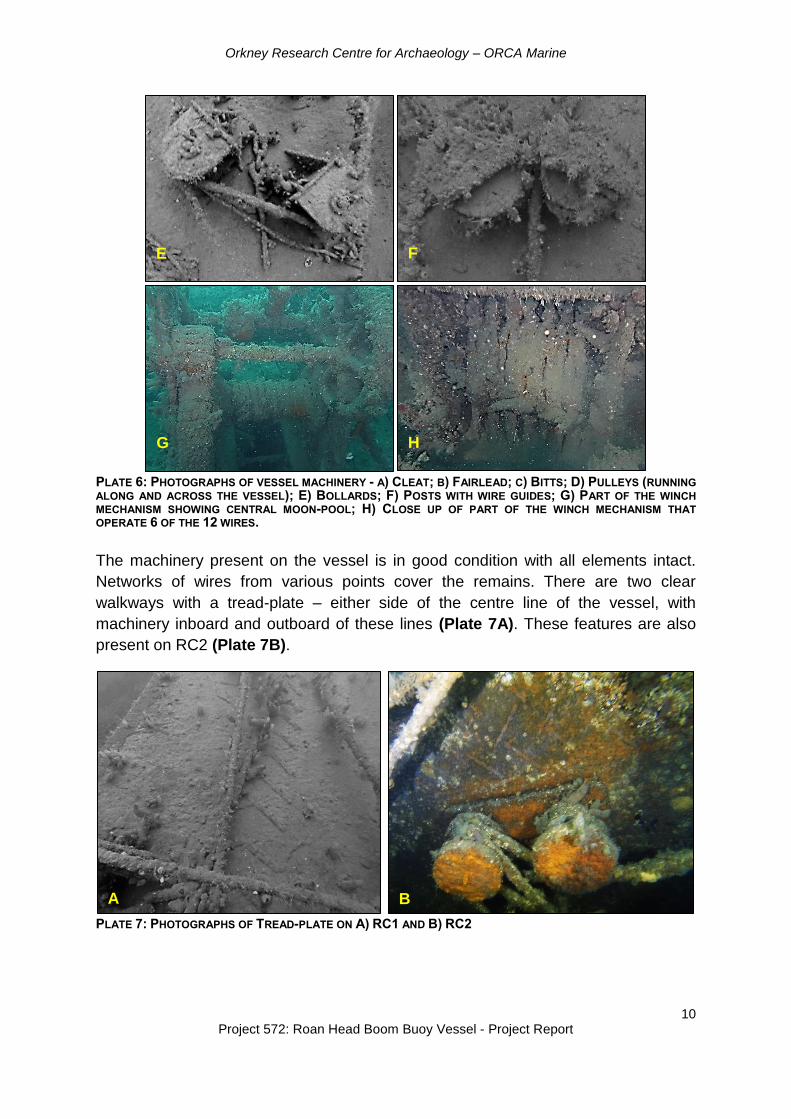
vessel), posts (with wire guides), cleats, fairleads, bollards and bitts (Plate 6A – 6F).
Each of the pulleys was associated with a 0.16m diameter aperture, and wires in situ
in the pulleys passed through tubes to the underside of the vessel. The central
section comprises several other pulleys and posts, surrounding a large winch which
has the capacity to operate twelve wires (Plate 6G and 6H).
A B
C D
Orkney Research Centre for Archaeology – ORCA Marine
10 Project 572: Roan Head Boom Buoy Vessel - Project Report
PLATE 6: PHOTOGRAPHS OF VESSEL MACHINERY - A) CLEAT; B) FAIRLEAD; C) BITTS; D) PULLEYS (RUNNING
ALONG AND ACROSS THE VESSEL); E) BOLLARDS; F) POSTS WITH WIRE GUIDES; G) PART OF THE WINCH
MECHANISM SHOWING CENTRAL MOON-POOL; H) CLOSE UP OF PART OF THE WINCH MECHANISM THAT
OPERATE 6 OF THE 12 WIRES.
The machinery present on the vessel is in good condition with all elements intact.
Networks of wires from various points cover the remains. There are two clear
walkways with a tread-plate – either side of the centre line of the vessel, with
machinery inboard and outboard of these lines (Plate 7A). These features are also
present on RC2 (Plate 7B).
PLATE 7: PHOTOGRAPHS OF TREAD-PLATE ON A) RC1 AND B) RC2
E
C
C
F
C
C
G
C
C
H
C
C
A B

Orkney Research Centre for Archaeology – ORCA Marine
11 Project 572: Roan Head Boom Buoy Vessel - Project Report
In the northwest corner of the site, a large pile of circular and ovular boom buoys and
associated nets was observed. The buoys showed evidence of corrosion around
distinct circular holes but were otherwise intact (Plate 8). The circular holes are likely
to have been caused by small artillery shells used to sink the buoys. It is probable
that these buoys were sunk after RC1 as they overlay the wreckage around the
middle section.
PLATE 8: PHOTOGRAPHS OF BOOM BUOYS AND NETTING IN THE NORTHWEST CORNER OF THE SITE
RC1 overlies the remains of RC2. RC2 appears to have been the same type of
vessel as RC1, however the wreck has capsized. The joins between the three
sections like those observed on RC1 are clearly visible and there are a number of
correlating apertures on the underside of the vessel. Several wires protrude from
these apertures. These are attached to steel beams onto which linear piles of boom
netting are secured (Plate 9). This boom netting lies off to the southeast side of RC2.
PLATE 9: RC2 BOOM NETTING: A) SHOWING WIRES CONNECTING TO STEEL BEAMS FROM UNDERSIDE OF
RC2; B) BOOM NET ATTACHED TO THE STEEL BEAMS
A B

Orkney Research Centre for Archaeology – ORCA Marine
12 Project 572: Roan Head Boom Buoy Vessel - Project Report
In the centre of the middle section there is a large circular aperture (known as a
moon-pool, which is a hole in a vessel that provides access to the water). This was
directly over the remains of a crushed winch (Plate 10) – supporting the above
interpretation that the two vessels are likely to be identical.
PLATE 10: RC2 WINCH AND MOON-POOL: A) MOON-POOL ON UNDERSIDE OF RC2; B) VIEW INTO MOON-POOL SHOWING PART OF THE WINCH; C) REMAINS OF INVERTED CRUSHED WINCH ON THE ‘DECK’ OF RC2
Spars A, B and C are long steel tubes comprising several sections of piping joined
together with flanges. As discussed above, the flanges of Spar C are visible on the
side scan sonar survey data, and this has led to the identification of several other
spars in the surrounding area.
Divers also made an assessment of the boom buoys and netting to the northwest of
RC1 and RC2. This was found to be a coherent unit of boom netting and buoys. The
buoys were spaced at regular intervals, likely in their original positions along the
nets. The remains are largely intact, though some of the buoys are broken up. There
is very little marine growth (short animal turf) on either the buoys or nets. The buoys
have clear small artillery shell holes and there is some moderate corrosion around
these edges.
A B
C

Orkney Research Centre for Archaeology – ORCA Marine
13 Project 572: Roan Head Boom Buoy Vessel - Project Report
6. DISCUSSION
6.1 IDENTIFICATION
RC1 and RC2 are the remains of Anti-Torpedo Close Protection Pontoons (ATCPP)
(ADM116/5790: 70). Admiralty records indicate that the pontoons were brought into
service in Scapa Flow in March 1941 to act as close protection for vessels in the
Flow from aircraft launch torpedoes.
In November 1940 the British launched an air attack on the Italian harbour of
Taranto. The battle resulted in large Italian losses (half the capital ships of the Italian
Navy were lost in one night) because although anti-torpedo baffles were deployed,
there was no close protection for the ships at anchor (ADM223/336).
Fearing that such an attack could be used against British assets, the Royal Navy
trialled a number of approaches for ATCP (including concrete barges, dumb barges,
roller nets, spar protection and pontoons), before finally opting for deployment of
Landing Craft Tanks (LCTs) adapted to take close protection nets (ADM1/12757). It
should be noted that the Spars A, B and C identified during the side scan sonar and
diving surveys are not considered representative of spar protection defences.
Historic photographs show that the pontoons are held away from the ships they are
protecting by linear beams known as spars. Spars A, B and C are examples of these
(Plate 11).
PLATE 11: EXAMPLES OF SPARS USED TO KEEP PONTOONS AWAY FROM THE SHIPS THEY ARE PROTECTING
Fender beams
(spars)

Orkney Research Centre for Archaeology – ORCA Marine
14 Project 572: Roan Head Boom Buoy Vessel - Project Report
ATCPP are described as being 90 foot long, replicating the dimensions of all the
rectangular contacts identified by the surveys completed during this project.
Individual pontoons would have been “secured end to end to the required length of
defence” (ADM1165790: 70). The pontoons would have had nets secured
underneath one side of them to a depth of 40 feet (the standard depth of close
protection anti-torpedo netting) (ADM1/12757).
These pontoons were found to be unsatisfactory, as they were hard to manoeuvre,
required a lot of maintenance and were not suitable for the conditions prevailing in
Scapa Flow. As a result they were unrigged and decommissioned in April 1942 and
were replaced by spar defence nets.
The depth of netting beneath the vessel also restricted the docking of the pontoons
alongside harbour facilities, suggesting that they would have been stored on
nearshore moorings. Historic charts of the area to the north of Flotta show the
positions of eighteen mooring buoys close to shore but in sufficient water depth to
facilitate the storage of these vessels with their associated netting. Post processing
of the side scan sonar data show that the target site (RC1 and RC2) and the second
pair of rectangular contacts (RC4 and RC5) are situated close to specific moorings
indicated on the historic chart. This could support the interpretation that these
moorings were used to store the pontoons when not deployed (Figure 3).
Historic photographs of the pontoons indicate that boom buoys were not part of the
deployed ATCP system. It is possible that additional boom netting and buoys were
also stored alongside these vessels in light of the extensive and coherent piles of
boom net associated with RC1 and RC2.
There are potential discrepancies within the Admiralty records as to how many
pontoons would have been in use during this period. Admiralty file (ADM116/5790:
70) indicates that there were 17 units at Scapa Flow, noting that each unit was
sufficient to protect one ship. At present it is unclear as to how many pontoons made
up a unit – as a single pontoon would not have had sufficient length to protect an
average sized vessel. Admiralty file ADM1/12757 (Sheet A: Close Protection
Summary) which dates to the 16 October 1942, indicates that one “set” of pontoons
was still “in use” at Scapa. It is unclear as to how many pontoons comprise a “set”. It
should be noted however that this document post-dates the reported
decommissioning of the pontoons.

Orkney Research Centre for Archaeology – ORCA Marine
15 Project 572: Roan Head Boom Buoy Vessel - Project Report
6.2 CONSTRUCTION AND USE
RC1, RC2 and historic records of the ATCPP’s indicate that each 90 foot pontoon
comprises three 30 foot sections, made of steel. The top edges of the pontoons have
a wooden rubbing strip for protection (Plate 12).
PLATE 12: EVIDENCE OF WOODEN RUBBING STRIP
There is an ovular access hatch on each section facilitating access to the inside of
the pontoon. The sections are bolted together as shown in Plate 13.
PLATE 13: JOIN BETWEEN TWO SECTIONS OF THE PONTOON

Orkney Research Centre for Archaeology – ORCA Marine
16 Project 572: Roan Head Boom Buoy Vessel - Project Report
There is a large winch on the centre section, which operates twelve wires – six to
each end of the pontoon. This winch would have been used to raise or lower the
anti-torpedo netting on one side of the vessel. This would have created a net wall
that would have protected the ship. For this to be effective the nets secured by the
pontoons needed to be more than 60 foot away from the ship that was being
protected (Bureau of Ordnance 1944: 63).
The winches on the pontoons that were recorded during this survey indicate that wire
was pulled along the pontoon, whereas similar pontoons in operation at other bases
(e.g. Rosyth) show winches to operate at 90 degrees to those at Scapa Flow (Plate
14) – pulling wire laterally across the pontoon, rather than along it.
PLATE 14: ALIGNMENT OF WINCH ON PONTOONS DEPLOYED FROM ROSYTH (ADM244-26).
The historic photos of the pontoons in operation protecting the HMS Duke of York in
the Firth of Forth clearly show the operational challenges involved with their
deployment. Sailors are shown standing on the pontoons, several of which are
attached together, whilst they are being towed into position. The images suggest that
there would have been some railings around the edges of the pontoons. These are
no longer present on the pontoons identified and recorded during these surveys
(Plate 15).

Orkney Research Centre for Archaeology – ORCA Marine
17 Project 572: Roan Head Boom Buoy Vessel - Project Report
PLATE 15: PONTOONS IN OPERATION PROTECTING HMS DUKE OF YORK IN THE FIRTH OF FORTH (ADM
224/26)

Orkney Research Centre for Archaeology – ORCA Marine
18 Project 572: Roan Head Boom Buoy Vessel - Project Report
6.3 OTHER KNOWN ATCPP SITES
In addition to the submerged pontoons at the target sites, a further two shore based
sites can now be confirmed as ATCPP.
6.3.1 ROAN HEAD, FLOTTA (CANMORE ID 249683)
The first is the largely intact remains of a pontoon on the beach on Flotta, referenced
in the Canmore record for the remains of anti-submarine boom defences (Canmore
ID 249683) as “…a flat metal structure extends into the intertidal zone on the Flotta
side of Calf Sound. It is 1m wide and at least 5m long. The remnants of winding gear
are attached to the seaward end”. Images of this pontoon are shown in Plate 16.
PLATE 16: REMAINS OF A PONTOON ON ROAN HEAD, FLOTTA
A B
C
Reported base of a
beacon Discarded boom net

Orkney Research Centre for Archaeology – ORCA Marine
19 Project 572: Roan Head Boom Buoy Vessel - Project Report
Two sections of the pontoon currently rest in the inter-tidal zone to the west of a
large pile of discarded boom netting and the reported remains of a 20th-century
beacon (Plate 16C), although it should be noted that there are no charted beacons
in the area. It is possible that this is the remains of an anchor for one of the Hoxa
booms. The third section has broken away and is resting perpendicular to the
midsection in the water. There is evidence to suggest that some salvage has taken
place, particularly on the remains of the larger section, as some of the fittings have
been removed or partly removed and there is evidence of sections of burning (Plate
17).
PLATE 17: EVIDENCE OF BURNING INDICATING SALVAGE OF MACHINERY
The features on this pontoon replicate exactly those found on the sites underwater.
Examples of these can be seen in Plate 18.
PLATE 18: EXAMPLES OF FEATURES ON THE FLOTTA BARGE REPLICATED UNDERWATER

Orkney Research Centre for Archaeology – ORCA Marine
20 Project 572: Roan Head Boom Buoy Vessel - Project Report
6.3.2 HOXA HEAD (CANMORE ID 314006)
The more dispersed remains of a second pontoon can be found on the rocks
beneath Hoxa battery. The debris is described in the Canmore site record for Leynei
Geo (Canmore ID 314006) as “fragments of a large metal structure, possibly part of
a ship or boom, are wedged fast between the rocks” (Plate 19).
PLATE 19: DISTRIBUTION OF PONTOON WRECKAGE AT HOXA
This site includes the remains of at least one section of a pontoon (broken and
present in two portions). One large portion measuring 3.13m long by 3m wide with a
height of 1.2m is half way up the beach. Four circular apertures and associated
tubes can be seen (Plate 20).
A second more fragmentary portion, wedged between rocks closer to the low water
mark is 3.18m long, but is too broken up to gauge other dimensions (Plate 21A and
21B). This is associated with several corroded piles of wire (Plate 21C). Although
the machinery and fittings from the pontoon are no longer in situ, likely a result of the
high energy environment they rest in, a winch with the same configuration of those
observed on Flotta and on the target wreck sites was observed close to the low
water mark in the vicinity of the rest of the wreckage (Plate 21D).
The winch, the join configuration, available dimensions and the presence of the
apertures and associated tubes have been used to confirm the identity of the
remains.
Winch
Dispersed
wreckage

Orkney Research Centre for Archaeology – ORCA Marine
21 Project 572: Roan Head Boom Buoy Vessel - Project Report
PLATE 20: MORE INTACT PORTION OF PONTOON SECTION AT HOXA
PLATE 21: DISPERSED PONTOON DEBRIS AT HOXA: A AND B) FRAGMENTARY REMAINS OF A PORTION OF
PONTOON SECTION; C) CORRODED NET/WIRES; D) WINCH MECHANISM
Circular
aperture
A
B
C D

Orkney Research Centre for Archaeology – ORCA Marine
22 Project 572: Roan Head Boom Buoy Vessel - Project Report
7. CONCLUSIONS AND FUTURE WORK
The side scan sonar surveys of the area surrounding the target site revealed
numerous features including several concentrations of boom defence debris. That
said, there were fewer features than anticipated compared to the quantity of debris
observed in foul ground areas surveyed as part of the Scapa Flow 2013 Marine
Archaeology Survey (Christie et al. 2014: 56-59). These surveys successfully
recorded the target site off the north coast of Flotta, highlighting the presence of two
distinct vessels, rather than a single wreck. This was associated with two coherent
concentrations of boom defence debris and three spars.
The diving surveys have documented that pontoons RC1 and RC2 are in good
condition, observing that both pontoons were identical; populated with a variety of
machinery including pulleys, posts, bollards, bitts, fairleads and cleats. A large winch
was observed in the central section of both vessels. Although directly associated
with boom buoys, historic photographs of the pontoons in service indicate that these
were not part of the defences deployed by the pontoons (as there are no buoys
surrounding the pontoons in these photographs). It is possible that these represent
the subsequent sinking of one (or more) coherent units of boom net and buoys.
The vessels were identified as being the remains of experimental Anti-Torpedo
Close Protection Pontoons, used in the close protection of vessels at anchor from
aircraft launch torpedoes. The pontoons were only in operation for 13 months (March
1941 – April 1942) and few were brought into service – with the majority of the units
deployed in Scapa Flow and Rosyth. As such they represent a rare heritage
resource for which very little is known about their operation.
The submerged remains have the same configuration as two other vessels - one in
the intertidal zone of Roan Head and one on the beach at Hoxa. It is hypothesised
that the remains three rectangular contacts (RC3, RC4 and RC5) identified by the
side scan sonar surveys are other further examples of these craft. If these contacts
are confirmed as pontoons, this could suggest that these vessels were stored on the
historic moorings that populate the area when they were not deployed to protect
ships in Scapa Flow.
Although the surveys provided an overview of the extent of the remains at the target
sites (and others observed), it was not within the scope of the project to produce
plans of the vessels and their associated wiring. More detailed diver and ROV
mapping surveys undertaken at these sites to record them in detail would contribute
to a fuller understanding of the resource, and contribute to longer term management
and monitoring programmes.
It is recommended that the RC3, RC4, RC5 and the circular feature (CC1) observed
in proximity to RC4 and RC5 should be the subject of further investigation to confirm
the identity of the remains, to document their condition and to map their
configuration. Evidence from historic photographs suggest that the winches on the

Orkney Research Centre for Archaeology – ORCA Marine
23 Project 572: Roan Head Boom Buoy Vessel - Project Report
central sections of pontoons deployed from Rosyth were oriented to pull cables
across, rather than along the vessel - how does this compare to the three
rectangular contacts? More extensive diving surveys around these sites should also
be completed to determine whether there is any evidence of mooring blocks in their
vicinity.
It may be possible to complete some of these surveys by involving the local diving
community through the delivery of training programmes such as the Nautical
Archaeology society courses; however, some of the sites are in deep water which
would restrict survey time. It is therefore suggested that the initial record of the other
submerged sites be conducted using an ROV.
While it is not within the remit of this survey project to address management issues,
the evidence from this project (and the outcomes of previous surveys) should
contribute to HS and stakeholders formulating appropriate management and
monitoring strategies for heritage assets with Scapa Flow resource more broadly.

Orkney Research Centre for Archaeology – ORCA Marine
24 Project 572: Roan Head Boom Buoy Vessel - Project Report
8. BIBLIOGRAPHY
Bureau of Ordnance (1944) Net and Boom Defenses. Bureau of Ordnance
Publication. Accessed from:
http://www.maritime.org/doc/netsandbooms/index.htm.
Christie, A.C., Heath, K., and Littlewood, M.E., (2014) Scapa Flow 2013 Marine
Archaeology Survey: Final Report. Accessed from
http://www.scapaflowwrecks.com/cms-assets/documents/158613-
94536.450scapa-project-reportfinal.pdf
Dresch, P. and McCarthy, J. (2012) Archaeological Interpretation of Multibeam Data
and Desk-Based Assessment. Wessex Archaeology: Edinburgh Accessed from:
http://www.scribd.com/doc/97523266/Scapa-Flow-Wreck-Surveys
Plets, R., Dix, J. and Bates, R. (2013) Marine Geophysics Data Acquisition,
Processing and Interpretation: Guidance Notes. English Heritage.
Historic Scotland (2012) The Marine Historic Environment: Strategy for the
protection, management and promotion of marine heritage 2012-15
Pollard, E., Littlewood, M., Saunders, M., Forbes, R., & Heath, K. (2012) Project
Adair: Mapping Marine Heritage Sites in Orkney and the Pentland Firth: Desk-
based assessment. ORCA Marine Project No: 293, for RCAHMS and HS.
http://orapweb.rcahms.gov.uk/wp/00/WP000721.pdf
ScapaMap2 (2006) Marine Heritage Monitoring with High-Resolution Survey Tools:
Scapa Flow 2001-2006. http://www.scapamap.org/reports.php
Archive Sources
The National Archives, Kew Admiralty Files:
ADM116/5790: Main Fleet Base - Scapa Flow: inception, development and
history. Includes 200 photographs depicting: Scapa Flow, Orkney: pictures of
ships, installations, defences, accommodation, personnel and anchorage.
Dated 1937-1946.
ADM1/12757: Ships and Vessels (91): Anti-torpedo close protection craft for
capital ships
ADM244/26: Close protection of HM Ships against torpedoes.
ADM223/336: Taranto: Attack by Fleet Air Arm

!
!
!
!
!
!
!
!
!
!
!
!
!
!
!
!
!
!
!
!
!
!
!!
!
!!
RC3RC3RC3RC3
RC5RC5RC5RC5RC4RC4RC4RC4
RC1RC1RC1RC1
RC2RC2RC2RC2
CC1CC1CC1CC1
BDD1BDD1BDD1BDD1
BDD2BDD2BDD2BDD2
BDD5BDD5BDD5BDD5
BDD3BDD3BDD3BDD3
Unknown1Unknown1Unknown1Unknown1
LC1LC1LC1LC1
LC2LC2LC2LC2
LC3LC3LC3LC3LC4LC4LC4LC4
LC6LC6LC6LC6LC5LC5LC5LC5
LC7LC7LC7LC7LC8LC8LC8LC8
BDD4BDD4BDD4BDD4LC9LC9LC9LC9
LC10LC10LC10LC10
493846
494346
494846
495346
495846
496346
6522930
6523430
6523930
6524430
- X:\MarineArchaeology\O
RCA M
arine Projects\572_HS_Boom_Buoys\G
eomatics\G
IS\572_Fig1_2015-03-18.m
xd*M
EL*190315
0 0.5 km @ A31:8,000
477250
487250
497250
507250
517250
6519082
6529082
6539082
6549082
0 10 Km
@ A31:500,000
Figure 1: Mosaic of side scan survey runs
showing distribution of observed features
QA by: ACC*190315
! BDD = Boom Defence Debris
CC = Circular Contact
LC = Linear Contact
RC = Rectangular Contact
Unknown Contact
Basemap
! Contact from side scan survey
Category
Coordinate System: WGS1984 UTM Zone 30N
© SeaZone Solutions Limited 2005, [SZ 112011.016]

494327
494347
494367
494387
6523019
6523039
6523059
6523079
0 20m
@ A31:500
- X:\MarineArchaeology\ORCA Marine Projects\572_HS_Boom_Buoys\Geomatics\GIS\572_Fig2_2015-03-19.mxd*MEL*190315
Coordinate System: WGS1984 UTM Zone 30N
!
493000
494000
495000
496000
6522000
6523000
6524000
0 1 Km
Figure 2: Side scan sonar and stills images of RC1 and RC2
QA by: ACC*190314
@ A31:40,000
© SeaZone Solutions Limited 2005, [SZ 112011.016]
A: Machinery on RC1 showing fairlead, post (with wireguide) and pulley
B: Winch on RC1
D: Netting attached to steel beams with spar B in the background
E: Apertures and wire on underside of RC2. Wires join steel beams like those shown in D
F: Boom buoys and net on northwest side of RC1, with RC1 visible in the background
C: End of RC1 showing rubber joining mechanism
AAAA
BBBB
CCCC
DDDD
EEEE
FFFF
RC2RC2RC2RC2
RC1RC1RC1RC1

!!
! !
!!
!
!
!
!
!
!
!
!
!
!
!
!
!
!
!
!
!
RC3
RC5
RC4
RC1
RC2
49
35
36
49
40
36
49
45
36
6522824
6523324
- X
:\M
ari
ne
Arc
ha
eo
log
y\O
RC
A M
ari
ne
Pro
jec
ts\5
72
_H
S_
Bo
om
_B
uo
ys
\Ge
om
ati
cs
\GIS
\57
2_
Fig
3_
20
15
-03
-18
.mx
d*M
EL
*19
03
15
0 0.5 Km
UKHO 1940, Chart F.083 South West Portion of Scapa Flow Including Cantick and Switha Sands @ A31:5,000 Figure 3: Distribution of rectangular contacts in
relation to moorings detailed on historic chart
QA
by
: A
CC
*19
03
15
47
72
50
48
72
50
49
72
50
50
72
50
51
72
50
6519082
6529082
6539082
6549082
0 10 Km
@ A31:5,000
! Rectangular contact from side scan survey
! Mooring shown on Chart F.083
Basemap
Coordinate System: WGS1984 UTM Zone 30N
© SeaZone Solutions Limited 2005, [SZ 112011.016]