orion-1 operation (hw revision 1) - rollanetjoeh/projects/orion/orion_operation.pdf · orion-1...
TRANSCRIPT
© Joseph M. Haas, 9/05/2016, all rights reserved 1
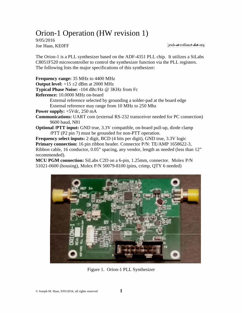
Orion-1 Operation (HW revision 1) 9/05/2016 Joe Haas, KE0FF The Orion-1 is a PLL synthesizer based on the ADF-4351 PLL chip. It utilizes a SiLabs C8051F520 microcontroller to control the synthesizer function via the PLL registers. The following lists the major specifications of this synthesizer: Frequency range: 35 MHz to 4400 MHz Output level: +15 ±2 dBm at 2000 MHz Typical Phase Noise: -104 dBc/Hz @ 3KHz from Fc Reference: 10.0000 MHz on-board External reference selected by grounding a solder-pad at the board edge External reference may range from 10 MHz to 250 Mhz Power supply: +5Vdc, 250 mA Communications: UART com (external RS-232 transceiver needed for PC connection) 9600 baud, N81 Optional /PTT input: GND true, 3.3V compatible, on-board pull-up, diode clamp /PTT (P2 pin 7) must be grounded for non-PTT operation. Frequency select inputs: 2 digit, BCD (4 bits per digit), GND true, 3.3V logic Primary connection: 16 pin ribbon header. Connector P/N: TE/AMP 1658622-3, Ribbon cable, 16 conductor, 0.05” spacing, any vendor, length as needed (less than 12” recommended). MCU PGM connection: SiLabs C2D on a 6-pin, 1.25mm, connector. Molex P/N 51021-0600 (housing), Molex P/N 50079-8100 (pins, crimp, QTY 6 needed)
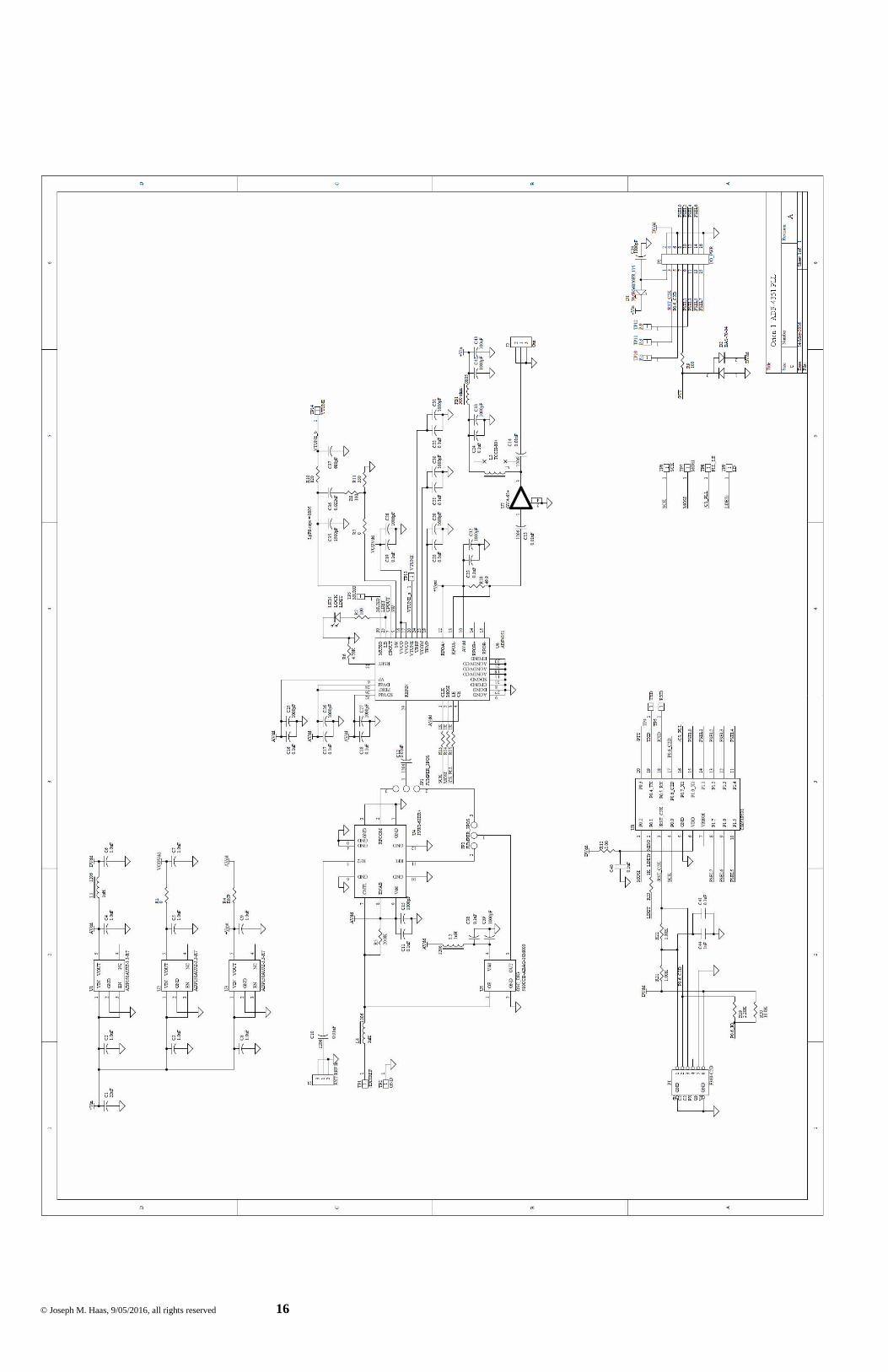
Figure 1. Orion-1 PLL Synthesizer
© Joseph M. Haas, 9/05/2016, all rights reserved 2
Operation The Orion operates from a 5V supply. All power and control signals for normal operation are available at the main connector, P2. At a minimum, the Orion requires +5v and GND for pre-programmed, single frequency operation. P1 Pinout SiLabs PGMR Pinout /RST 1 7 C2D 2 4 /RST_C2K 3 5 n/c 4 GND 5 2, 3, 9 +3.3V 6 10 P2 Pinout +5V in 1 2 GND /RST_C2K (TXD) 3 4 +3.3V out C2D (RXD) 5 6 GND /PTT 7 8 FSEL0 (LSD b0) (LSD b1) FSEL1 9 10 FSEL2 (LSD n2) (LSD b3) FSEL3 11 12 FSEL4 (MSD b0) (MSD b1) FSEL5 13 14 FSEL6 (MSD b2) (MSD b3) FSEL7 15 16 GND Note: /RST_C2K and C2D are the SiLabs C2D programming protocol signals. These pins may optionally be re-assigned (using trace-cuts and jumpers) as the UART serial connections. In this case, P1 is required to allow MCU firmware programming. Note: All logic signals are 3.3V logic and will NOT tolerate higher voltage logic Frequency Selection (Channels) The Orion functions as a 99 channel (channels 01 – 99), pre-programmed frequency source with an “idle” channel (CH#00). Each channel consists of six, 32-bit registers that are transferred to the ADF-4351 when the channel is selected. These six registers comprise the entire register set of the ADF-4351 and allow for complete control of the PLL functionality. Refer to the ADF-4351 datasheet for additional information regarding these registers. It is recommended that users utilize the ADF-435x evaluation software provided by Analog Devices when defining a register set for a particular channel definition. From this software, the contents of the six registers can be copied to a spreadsheet for transfer into the Orion MCU. Programming the channels is covered in a later section of this document.
© Joseph M. Haas, 9/05/2016, all rights reserved 3
The 8-bit, dual BCD logic inputs allow the PLL channel to be selected by applying GND (0V) or open (+3.3V) levels to the FSEL inputs. To switch channels, simply apply the desired BCD bit pattern (using GND true logic) to the FSEL[7:4] (10’s digit) and FSEL[3:0] (1’s digit) inputs. Note: the MCU will change channels immediately upon detecting a change in the channel setting. Thus, if individual bits are changed over even just a few ms, it may be possible for the Orion to select one or more unintended channels as the inputs settle. GND True means that a grounded bit = logic “1” and an open bit = logic “0”. Thus, channel 18 would be set by grounding FSEL4 and FSEL3, with all other FSEL input open (A DIP switch or GND common BCD selector switch works well for this purpose). Optional /PTT Function (CH00 Force: 2nd Frequency, or Mute) If desired, the /PTT input can be used to switch the Orion PLL register set from the currently selected channel (/PTT = GND) to the register set programmed in CH00 (/PTT = open), and vis-à-vis. This feature is intended to operate as a mute input to the synthesizer, but any desired data can be programmed into CH00, so it could also serve many other functions as well (e.g., RX LO for /PTT = high and TX LO for /PTT = low). If the PTT function is not desired, the /PTT input must be grounded to permit the frequency select input to always be recognized and acted upon by the Orion software. In order to accomplish the mute function, CH00 must be programmed with a register set that causes the PLL to mute its RF output. There are a number of different bit fields and patterns that can accomplish this. The following register set is the one used by the factory default software load to provide the mute function: aaaaaaaa bbbbbbbb cccccccc dddddddd eeeeeeee ffffffff 00730010 08008029 00004E42 000004B3 00C50A04 00580005 CH00 can also be thought of as the “100th” channel of the Orion for applications where the PTT input is always grounded. CH00 then simply functions the same as the other 99 channels that are normally available and may be set to any desired PLL configuration. Serial Port The Orion MCU features a serial connection that can be used to program the MCU channel sets or to provide real-time frequency control of the PLL. An external RS-232 transceiver module is available as an option to allow RS-232 serial connection to Orion (this is not needed if +3.3V logic TXD/RXD signals are available from the host). At power-on, an initialization banner message is sent by Orion: ADF4351 PLL Driver Ver 1.1, de ke0ff 100 CH, gnd-true BCD, PTT hi = CH00 Serial cmd enabled pll>
© Joseph M. Haas, 9/05/2016, all rights reserved 4
The reset banner provides the software version and a brief list of version features. Primarily, this message is important for identifying the current software version, and verifying that the UART TX connection to the user terminal is working. The serial commands available are as follows: All commands are terminated with <CR> (ASCII 0x0d, <ENTER> on most keyboards). Serial port does not echo characters. Commands are 1 character, case sensitive. Hex data may be upper or lower case. ?: List Command Help Displays an abbreviated list of the available commands. E: Erase all channels Prompts the user: "Erase all, press Y to accept…" and waits 5 sec for input. Any character other than upper-case "Y", or a delay of more than 5 sec will cause this command to abort with no changes to the system. This command must be executed if the channel(s) to be programmed contain any data other than all 0xFF. M: Program (memory) channel Mxxaaaaaaaabbbbbbbbccccccccddddddddeeeeeeeeffffffff Programs channel "xx" (xx is BCD ASCII ‘00’ thru ‘99’) with “a..a” (R0), thru “f..f” (R5) values (each register field MUST be 8 HEX digits in length. Add leading ‘0’ digits if needed). Data is represented as ASCII hex (‘0’ thru ‘9’, ‘A’ thru ‘F’, or ‘a’ thru ‘f’). Space, comma, or TAB (ASCII 0x09) characters may be included between channel data characters for clarity, but the serial buffer limit is 62 characters per command line, including the command and channel# characters. If any invalid data is received, the command is aborted (with error message) and the channel is left un-programmed. Note: The “M” command processes one channel at a time. When uploading a file of programming commands, command lines that feature errors will not affect other command lines that are error-free. Z: Compare CRC Z hhhh Compares the FLASH CRC to the “hhhh” value provided in ASCII hex (the CRC must be 4 digits). Displays PASS if there is a match or FAIL otherwise. If FAIL, the global error flag is also set. Note: A one (1) second delay is provided to allow terminal upload to finish. As such, this should be the last command in an upload file if the CRC is known beforehand. If a 1 second delay is not sufficient, the “Q” command may be used to interrogate the pass/fail status of the upload.
© Joseph M. Haas, 9/05/2016, all rights reserved 5
C: Calculate Channel Data CRC c Calculates a CRC-16 value (using 0x1021 for the polynomial) based on the 2400 bytes in the channel array stored in FLASH memory and displays the result to the serial port. The MCU calculates the displayed CRC is by sequentially calling calcrc() (the code snippet below may be used to create an off-line CRC calculator if desired) with each byte in the array (2400 bytes, total), starting with CH00 R0 MS nybble (lowest address). “old_crc” = 0x0000 at the start of the calculation. Note: The CRC16 result for all channels erased is 0xB2CF. //------------------------------------------------- -------------------- // calcrc() calculates incremental crcsum using def ined poly // (xmodem poly = 0x1021) //------------------------------------------------- -------------------- U16 calcrc(U8 c, U16 oldcrc) #define POLY 0x1021 // xmodem polynomial U16 crc; U8 i; crc = oldcrc ^ ((U16)c << 8); for (i = 0; i < 8; ++i) if (crc & 0x8000) crc = (crc << 1) ^ POLY; else crc = crc << 1; return crc;
t: Temporary Channel t00aaaaaaaabbbbbbbbccccccccddddddddeeeeeeeeffffffff Programs the temporary channel using the same register syntax as the "M" command (the channel number is ignored, but must be present). The temp channel allows a register set to be input to the Orion without programming a FLASH channel. Once set, the temp command overrides the BCD inputs. PTT behaves normally and will not change the temp channel configuration (/PTT high will select CH00, and /PTT low will select the temp channel when valid). Selecting a new BCD channel, or programming a channel with the "M" command will cancel the temp channel. The temp channel command must then be re-entered to re-enable. r: Read Channel Registers rxx Displays channel "xx" (xx is BCD ASCII ‘00’ thru ‘99’) in the same format as is used by the “M” command. Spaces are inserted between register fields for clarity.
© Joseph M. Haas, 9/05/2016, all rights reserved 6
r-: Read All Channel Registers r- Sequentially displays all channels starting at CH00. The resulting output is in the “M” command syntax format and may be used to archive or clone an entire channel set for a given Orion board. rr: Read Temporary Channel Registers rr Displays temporary channel register values. Display format is: t00 aaaaaaaa bbbbbbbb cccccccc dddddddd eeeeeeee ff ffffff
i: Re-send last register set i Causes Orion to re-send the last selected resister set to the ADF4351 (/PTT = high: CH00; /PTT = low: the BCD or temporary channel set that was last selected). e: Echo Command-Line (debug) e Echo command line. This is a debug command that will echo the characters on the command line and is useful in verifying UART RXD operation. Q: Query Error Status Q Displays FAIL if there was an error encountered in an “M” or “t” command. Otherwise, PASS is displayed. QC: Clear Query Error Status QC Displays the current error status, then clears the status to PASS. While all of the above commands may be typed manually, the “M” and “t” commands are mainly intended to be used by either manually downloading a text file containing the commands, or by using a special-purpose PC program to send the commands after processing them from either a text or spreadsheet input.
© Joseph M. Haas, 9/05/2016, all rights reserved 7
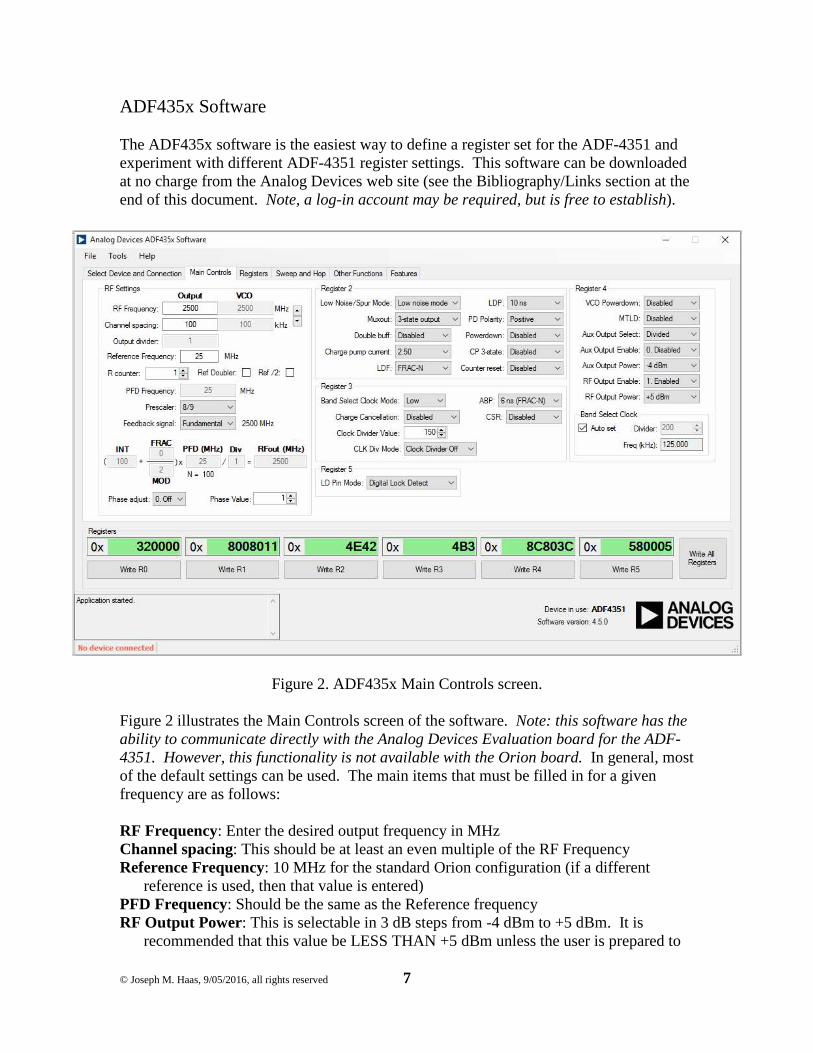
ADF435x Software The ADF435x software is the easiest way to define a register set for the ADF-4351 and experiment with different ADF-4351 register settings. This software can be downloaded at no charge from the Analog Devices web site (see the Bibliography/Links section at the end of this document. Note, a log-in account may be required, but is free to establish).
Figure 2. ADF435x Main Controls screen. Figure 2 illustrates the Main Controls screen of the software. Note: this software has the ability to communicate directly with the Analog Devices Evaluation board for the ADF-4351. However, this functionality is not available with the Orion board. In general, most of the default settings can be used. The main items that must be filled in for a given frequency are as follows: RF Frequency: Enter the desired output frequency in MHz Channel spacing: This should be at least an even multiple of the RF Frequency Reference Frequency: 10 MHz for the standard Orion configuration (if a different
reference is used, then that value is entered) PFD Frequency: Should be the same as the Reference frequency RF Output Power: This is selectable in 3 dB steps from -4 dBm to +5 dBm. It is
recommended that this value be LESS THAN +5 dBm unless the user is prepared to
© Joseph M. Haas, 9/05/2016, all rights reserved 8
monitor the operating temperature of the ADF-4351 to make sure that its temperature limits are not exceeded.
MTLD : (optional) This feature mutes the RF output (to less than -40 dBm) until the PLL lock detect is TRUE.
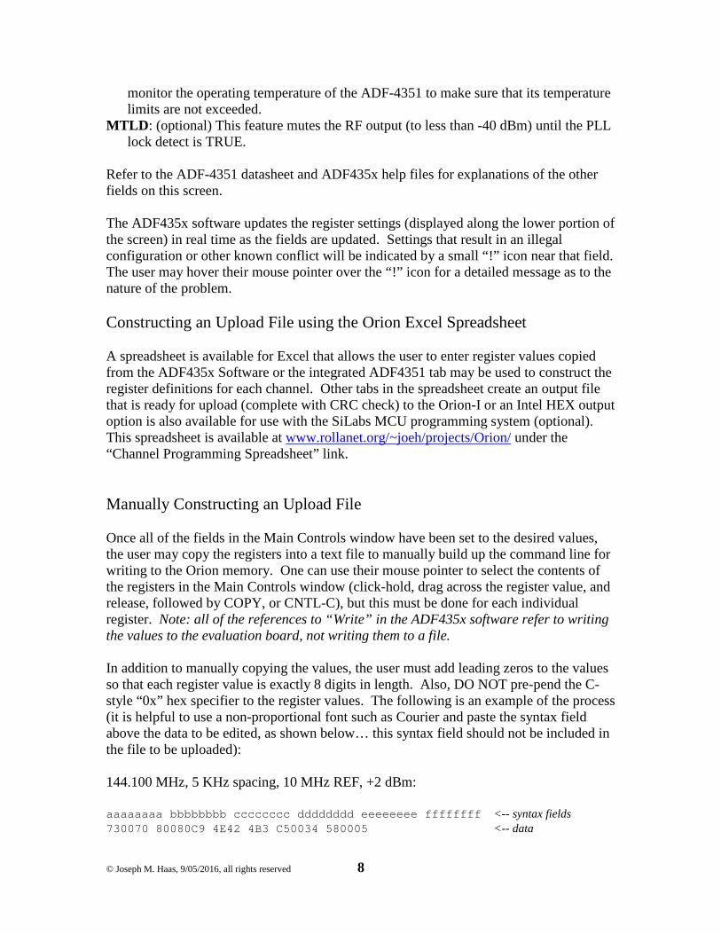
Refer to the ADF-4351 datasheet and ADF435x help files for explanations of the other fields on this screen. The ADF435x software updates the register settings (displayed along the lower portion of the screen) in real time as the fields are updated. Settings that result in an illegal configuration or other known conflict will be indicated by a small “!” icon near that field. The user may hover their mouse pointer over the “!” icon for a detailed message as to the nature of the problem. Constructing an Upload File using the Orion Excel Spreadsheet A spreadsheet is available for Excel that allows the user to enter register values copied from the ADF435x Software or the integrated ADF4351 tab may be used to construct the register definitions for each channel. Other tabs in the spreadsheet create an output file that is ready for upload (complete with CRC check) to the Orion-I or an Intel HEX output option is also available for use with the SiLabs MCU programming system (optional). This spreadsheet is available at www.rollanet.org/~joeh/projects/Orion/ under the “Channel Programming Spreadsheet” link. Manually Constructing an Upload File Once all of the fields in the Main Controls window have been set to the desired values, the user may copy the registers into a text file to manually build up the command line for writing to the Orion memory. One can use their mouse pointer to select the contents of the registers in the Main Controls window (click-hold, drag across the register value, and release, followed by COPY, or CNTL-C), but this must be done for each individual register. Note: all of the references to “Write” in the ADF435x software refer to writing the values to the evaluation board, not writing them to a file. In addition to manually copying the values, the user must add leading zeros to the values so that each register value is exactly 8 digits in length. Also, DO NOT pre-pend the C-style “0x” hex specifier to the register values. The following is an example of the process (it is helpful to use a non-proportional font such as Courier and paste the syntax field above the data to be edited, as shown below… this syntax field should not be included in the file to be uploaded): 144.100 MHz, 5 KHz spacing, 10 MHz REF, +2 dBm: aaaaaaaa bbbbbbbb cccccccc dddddddd eeeeeeee ffffff ff <-- syntax fields 730070 80080C9 4E42 4B3 C50034 580005 <-- data
© Joseph M. Haas, 9/05/2016, all rights reserved 9
Note that spaces were manually added between the registers. Next, add leading zeros to line up the data with the “syntax fields”: aaaaaaaa bbbbbbbb cccccccc dddddddd eeeeeeee ffffff ff 00730070 080080C9 00004E42 000004B3 00C50034 005800 05 <-- leading 0’s added Finally, add the command prefix: for the FLASH channel write, add “Mxx” (no spaces between the characters) where “xx” is the desired channel#, or “t00” for the temporary channel. The following depicts the same register set for both a FLASH channel and the temporary channel: M01 00730070 080080C9 00004E42 000004B3 00C50034 00 580005 t00 00730070 080080C9 00004E42 000004B3 00C50034 00 580005 Comments may be added to the file. Make the first character of comment lines a “;” and limit the comments to 60 characters per line. Note: The 60 character limit applies to all command lines for the Orion board. Also, to help prevent crashes during file transfers, keep the number of added spaces in command lines to a minimum. There is no limit to the number of comment lines, but just be aware that the comment lines add to the file transfer time. The following is an example of a finished channel write command: ;144.1 MHz, 5KHz chspc, 10MHz ref, +2dBm M01 00730070 080080C9 00004E42 000004B3 00C50034 00 580005 These command lines and any comments can be placed into one text file. All 100 channel locations may be programmed by a single upload operation, or multiple files may be used. Note: The Orion software does not check for erased locations before programming. Thus, attempts to write different data into the same channel, either in the same upload file or in separate files, will result in corrupted data for that channel.
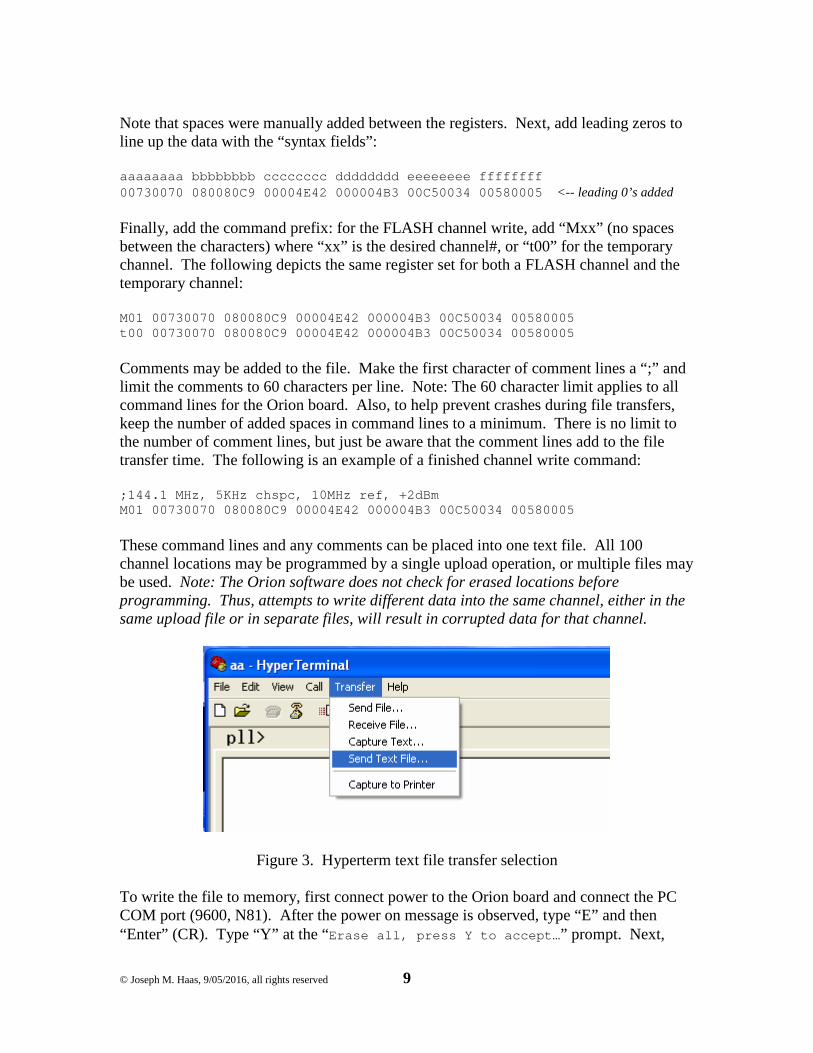
Figure 3. Hyperterm text file transfer selection To write the file to memory, first connect power to the Orion board and connect the PC COM port (9600, N81). After the power on message is observed, type “E” and then “Enter” (CR). Type “Y” at the “Erase all, press Y to accept… ” prompt. Next,
© Joseph M. Haas, 9/05/2016, all rights reserved 10
issue the “QC” command to clear the error status. Then, perform a text file upload using the terminal program of choice (for Hyperterm, see Figure 3). Some terminal programs will display the terminal progress as the file uploads (Hyperterm does this). If so, the “Chan pgmd! ” message should be observed after each “M” line is transferred. Once the file transfer is complete, one should perform a “Q” command to verify that there were no errors encountered in the downloaded data. The CRC16 check (“c” or “Z” command) should also be performed. Note: The “Orion Channel Workbook” spreadsheet will include a “Z” command with the pre-calculated CRC for the data in that file. This will display a “PASS” or “FAIL” message 1 second after the transfer finishes. For the temporary register feature, one may follow the above steps to transfer the register set into the Orion, or use the “Orion Channel Workbook” spreadsheet to create the command line.
© Joseph M. Haas, 9/05/2016, all rights reserved 11
MCU Programming Cable Connections (Hardware revision 1) In order to program the MCU software or channel data using the MCU programming tools, the SiLabs programming adapter, software, and (for hardware rev 1) one of the adapter cables described below are needed. Note: The user made adapter cables described below are not required for hardware revision 2 or greater. The programming adapter is available from DigiKey or Mouser under the part number DEBUGADPTR1-USB (cost is about $35). The software can be obtained from the SiLabs web site at: http://www.silabs.com/products/mcu/Pages/8-bit-microcontroller-software.aspx When only the channel data is to be programmed, this may be accomplished by the UART serial connection which does not require the SiLabs programming adapter. Hardware revision 1 boards will require an external RS-232 transceiver circuit (see below). SiLabs P2 Programming Adapter Cable (NO UART jumpers)
Harting P/N TE/AMP P/N 09185106324 1658621-3 Signal USB Pgm Adapter J2 (P2 mate) /RST_C2K 5 3 +3.3V out 10 4 C2D 4 5 GND 2, 3, 9 6
Note: This connection may be used only if the UART jumper options are not exercised (the factory default). If the UART jumpers are installed, the P1 adapter cable (below) must be used.
SiLabs P1 Programming Adapter Cable (UART jumpers installed)
Harting P/N Molex P/N 09185106324 51021-0600, plus qty 5 pin P/N 50079-8100 Signal Pgm Adapter J1 (P1 mate) /RST_C2K 5 3 +3.3V out 10 6 C2D 4 2 GND 2, 3, 9 5 /RST 7 1 UART Connections (Hardware Rev 1) Hardware revision 1 features jumper options to allow the UART RXD and TXD connections to replace the C2K and C2D FLASH programming signals. Note: Hardware revision 2 and greater connects the UART to P2 by default with no option to modify the P2 connections. To exercise this option, the traces to the C2K and C2D connections must be cut, and jumper wires added from the TXD pad to TP11 (P2-3), and from the
© Joseph M. Haas, 9/05/2016, all rights reserved 12
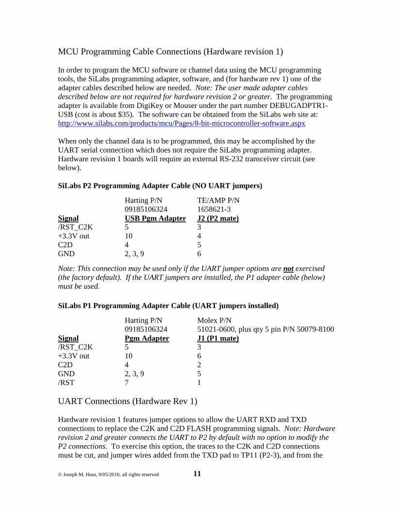
RXD pad to TP10 (P2-5). Figure 4 illustrates the cuts and jumpers that are needed. Use an Xacto-knife to cut a small gap (at least 0.01”/0.25mm) in the traces to be cut and use 30 AWG solid wire-wrap wire for the short jumpers.
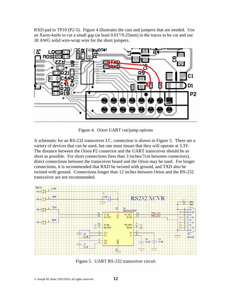
Figure 4. Orion UART cut/jump options A schematic for an RS-232 transceiver I.C. connection is shown in Figure 5. There are a variety of devices that can be used, but one must insure that they will operate at 3.3V. The distance between the Orion P2 connector and the UART transceiver should be as short as possible. For short connections (less than 3 inches/7cm between connectors), direct connections between the transceiver board and the Orion may be used. For longer connections, it is recommended that RXD be twisted with ground, and TXD also be twisted with ground. Connections longer than 12 inches between Orion and the RS-232 transceiver are not recommended.
Figure 5. UART RS-232 transceiver circuit
© Joseph M. Haas, 9/05/2016, all rights reserved 13
Bibliography/References
• ADF435x Software: • https://ez.analog.com/servlet/JiveServlet/download/10667-1-
30579/ADF435x_v4_5_0.zip • ADIsimPLL:
• https://form.analog.com/form_pages/rfcomms/adisimpll.aspx • SiLabs C8051F531 Datasheet and Programming Manual (search for C8051F531):
• http://www.silabs.com/products/mcu/Pages/default.aspx • Analog Devices ADF4351 Datasheet and UG-435 Evaluation Board User Guide:
• http://www.analog.com/en/products/rf-microwave/pll-synth/fractional-n-plls/adf4351.html
• Mini-Circuits GVA-62+ and JSW2-63DR+ Datasheets: • http://www.minicircuits.com
© Joseph M. Haas, 9/05/2016, all rights reserved 14
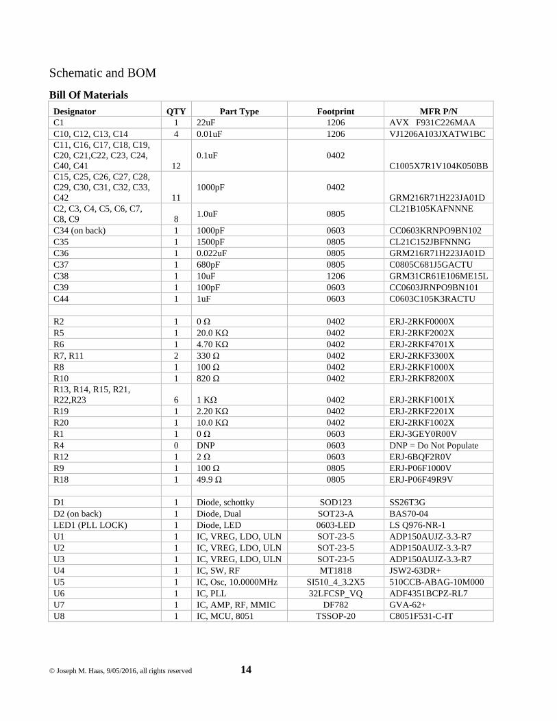
Schematic and BOM
Bill Of Materials
Designator QTY Part Type Footprint MFR P/N C1 1 22uF 1206 AVX F931C226MAA C10, C12, C13, C14 4 0.01uF 1206 VJ1206A103JXATW1BC C11, C16, C17, C18, C19, C20, C21,C22, C23, C24, C40, C41 12
0.1uF 0402 C1005X7R1V104K050BB
C15, C25, C26, C27, C28, C29, C30, C31, C32, C33, C42 11
1000pF 0402 GRM216R71H223JA01D
C2, C3, C4, C5, C6, C7, C8, C9 8
1.0uF 0805 CL21B105KAFNNNE
C34 (on back) 1 1000pF 0603 CC0603KRNPO9BN102 C35 1 1500pF 0805 CL21C152JBFNNNG C36 1 0.022uF 0805 GRM216R71H223JA01D C37 1 680pF 0805 C0805C681J5GACTU C38 1 10uF 1206 GRM31CR61E106ME15L C39 1 100pF 0603 CC0603JRNPO9BN101 C44 1 1uF 0603 C0603C105K3RACTU R2 1 0 Ω 0402 ERJ-2RKF0000X R5 1 20.0 KΩ 0402 ERJ-2RKF2002X R6 1 4.70 KΩ 0402 ERJ-2RKF4701X R7, R11 2 330 Ω 0402 ERJ-2RKF3300X R8 1 100 Ω 0402 ERJ-2RKF1000X R10 1 820 Ω 0402 ERJ-2RKF8200X R13, R14, R15, R21, R22,R23 6 1 KΩ 0402 ERJ-2RKF1001X R19 1 2.20 KΩ 0402 ERJ-2RKF2201X R20 1 10.0 KΩ 0402 ERJ-2RKF1002X R1 1 0 Ω 0603 ERJ-3GEY0R00V R4 0 DNP 0603 DNP = Do Not Populate R12 1 2 Ω 0603 ERJ-6BQF2R0V R9 1 100 Ω 0805 ERJ-P06F1000V R18 1 49.9 Ω 0805 ERJ-P06F49R9V D1 1 Diode, schottky SOD123 SS26T3G D2 (on back) 1 Diode, Dual SOT23-A BAS70-04 LED1 (PLL LOCK) 1 Diode, LED 0603-LED LS Q976-NR-1 U1 1 IC, VREG, LDO, ULN SOT-23-5 ADP150AUJZ-3.3-R7 U2 1 IC, VREG, LDO, ULN SOT-23-5 ADP150AUJZ-3.3-R7 U3 1 IC, VREG, LDO, ULN SOT-23-5 ADP150AUJZ-3.3-R7 U4 1 IC, SW, RF MT1818 JSW2-63DR+ U5 1 IC, Osc, 10.0000MHz SI510_4_3.2X5 510CCB-ABAG-10M000 U6 1 IC, PLL 32LFCSP_VQ ADF4351BCPZ-RL7 U7 1 IC, AMP, RF, MMIC DF782 GVA-62+ U8 1 IC, MCU, 8051 TSSOP-20 C8051F531-C-IT
© Joseph M. Haas, 9/05/2016, all rights reserved 15
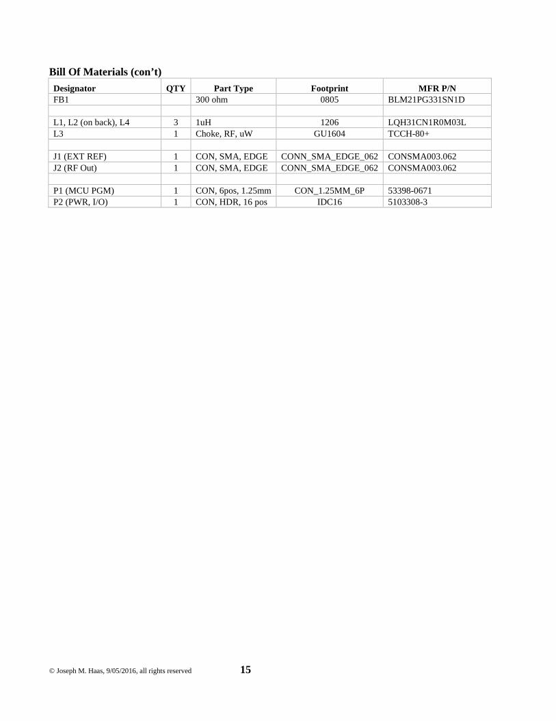
Bill Of Materials (con’t)
Designator QTY Part Type Footprint MFR P/N FB1 300 ohm 0805 BLM21PG331SN1D L1, L2 (on back), L4 3 1uH 1206 LQH31CN1R0M03L L3 1 Choke, RF, uW GU1604 TCCH-80+ J1 (EXT REF) 1 CON, SMA, EDGE CONN_SMA_EDGE_062 CONSMA003.062 J2 (RF Out) 1 CON, SMA, EDGE CONN_SMA_EDGE_062 CONSMA003.062 P1 (MCU PGM) 1 CON, 6pos, 1.25mm CON_1.25MM_6P 53398-0671 P2 (PWR, I/O) 1 CON, HDR, 16 pos IDC16 5103308-3
© Joseph M. Haas, 9/05/2016, all rights reserved 16