original instructions instrucciones originales ... · model ac1234-6 recover, recycle, recharge...
TRANSCRIPT

Model AC1234-6Recover, Recycle, Recharge Machine
for R1234yf A/C Systems
Original InstructionsInstrucciones originales
Instructions d’origine

DISCLAIMER: Information, illustrations, and specifications contained in this manual are based on the latest information available at the time of publication. The right is reserved to make changes at any time without obligation to notify any person or organization of such revisions or changes. Further, ROBINAIR shall not be liable for errors contained herein or for incidental or consequential damages (including lost profits) in connection with the furnishing, performance, or use of this material. If necessary, obtain additional health and safety information from the appropriate government agencies, and the vehicle, refrigerant, and lubricant manufacturers.
Description: Recover, recycle, and recharge machine for use with R1234yf equipped air conditioning systems.
PRODUCT INFORMATIONRecord the serial number and year of manufacture of this unit for future reference. Refer to the product identification label on the unit for information.
AC1234-6Serial Number: _______________________________Year of Manufacture: ____________

1AC1234-6 Rev. C
Table of Contents
Safety Precautions . . . . . . . . . . . . . . . . . . . . . . . . . . . . . . . . . . . . . . . . . . . 2Introduction TechnicalSpecifications . . . . . . . . . . . . . . . . . . . . . . . . . . . . . . . . . . . . . 5 FeaturesoftheAC1234-6 . . . . . . . . . . . . . . . . . . . . . . . . . . . . . . . . . . . 6 ControlPanelFunctions . . . . . . . . . . . . . . . . . . . . . . . . . . . . . . . . . . . . 8 SetupMenuFunctions . . . . . . . . . . . . . . . . . . . . . . . . . . . . . . . . . . . . . . 9Setup UnpacktheAccessoryKit . . . . . . . . . . . . . . . . . . . . . . . . . . . . . . . . . . 10 InstallOilDrainBottle . . . . . . . . . . . . . . . . . . . . . . . . . . . . . . . . . . . . . 10 PowerUptheMachine . . . . . . . . . . . . . . . . . . . . . . . . . . . . . . . . . . . . 11 RegistertheMachine . . . . . . . . . . . . . . . . . . . . . . . . . . . . . . . . . . . . . . 11 LanguageSelection . . . . . . . . . . . . . . . . . . . . . . . . . . . . . . . . . . . . . . . 12 UnitofMeasure . . . . . . . . . . . . . . . . . . . . . . . . . . . . . . . . . . . . . . . . . . 12 Date&TimeSetup . . . . . . . . . . . . . . . . . . . . . . . . . . . . . . . . . . . . . . . . 12 ServiceInstallationClearing . . . . . . . . . . . . . . . . . . . . . . . . . . . . . . . . 12 TankFillAdjustment . . . . . . . . . . . . . . . . . . . . . . . . . . . . . . . . . . . . . . . 13 Tank Filling . . . . . . . . . . . . . . . . . . . . . . . . . . . . . . . . . . . . . . . . . . . . . . 13 GarageData . . . . . . . . . . . . . . . . . . . . . . . . . . . . . . . . . . . . . . . . . . . . 14Operating Instructions VINEntry . . . . . . . . . . . . . . . . . . . . . . . . . . . . . . . . . . . . . . . . . . . . . . . 15 StoredData . . . . . . . . . . . . . . . . . . . . . . . . . . . . . . . . . . . . . . . . . . . . . 15 DiagnosticPressures . . . . . . . . . . . . . . . . . . . . . . . . . . . . . . . . . . . . . . 16 Printouts . . . . . . . . . . . . . . . . . . . . . . . . . . . . . . . . . . . . . . . . . . . . . . . . 16 Recovery . . . . . . . . . . . . . . . . . . . . . . . . . . . . . . . . . . . . . . . . . . . . . . . 17 Vacuum . . . . . . . . . . . . . . . . . . . . . . . . . . . . . . . . . . . . . . . . . . . . . . . . 19 HoseFlush . . . . . . . . . . . . . . . . . . . . . . . . . . . . . . . . . . . . . . . . . . . . . . 20 Charge . . . . . . . . . . . . . . . . . . . . . . . . . . . . . . . . . . . . . . . . . . . . . . . . . 21 Automatic . . . . . . . . . . . . . . . . . . . . . . . . . . . . . . . . . . . . . . . . . . . . . . . 23 SystemFlush . . . . . . . . . . . . . . . . . . . . . . . . . . . . . . . . . . . . . . . . . . . . 25Maintenance General . . . . . . . . . . . . . . . . . . . . . . . . . . . . . . . . . . . . . . . . . . . . . . . . 27 ElectricalProtection . . . . . . . . . . . . . . . . . . . . . . . . . . . . . . . . . . . . . . . 27 TankFillAdjustment . . . . . . . . . . . . . . . . . . . . . . . . . . . . . . . . . . . . . . . 27 Tank Filling . . . . . . . . . . . . . . . . . . . . . . . . . . . . . . . . . . . . . . . . . . . . . . 28 TankFillHoseFilterService . . . . . . . . . . . . . . . . . . . . . . . . . . . . . . . . 29 FilterChange . . . . . . . . . . . . . . . . . . . . . . . . . . . . . . . . . . . . . . . . . . . . 30 RefrigerantIdentifier . . . . . . . . . . . . . . . . . . . . . . . . . . . . . . . . . . . 32 CalibrationCheck . . . . . . . . . . . . . . . . . . . . . . . . . . . . . . . . . . . . . . . . 32 ReplaceOxygenSensorinRefrigerantIdentifier . . . . . . . . . . . . . . . . 33 ChangeVacuumPumpOil . . . . . . . . . . . . . . . . . . . . . . . . . . . . . . . . . . 35 EditPrintHeader . . . . . . . . . . . . . . . . . . . . . . . . . . . . . . . . . . . . . . . . . 36 ReplacePrinterPaper . . . . . . . . . . . . . . . . . . . . . . . . . . . . . . . . . . . . . 36 ReplaceServiceHosesand/orServiceCouplers . . . . . . . . . . . . . . . 36Replacement Parts . . . . . . . . . . . . . . . . . . . . . . . . . . . . . . . . . . . . . . . . . . 37Glossary . . . . . . . . . . . . . . . . . . . . . . . . . . . . . . . . . . . . . . . . . . . . . . . . . . 37Software Flow Chart . . . . . . . . . . . . . . . . . . . . . . . . . . . . . . . . . . . . . . . . . 38Troubleshooting Messages . . . . . . . . . . . . . . . . . . . . . . . . . . . . . . . . . . . . . . . . . . . . . . . 39 Procedures . . . . . . . . . . . . . . . . . . . . . . . . . . . . . . . . . . . . . . . . . . . . . . 41Storage and Transportation of Equipment . . . . . . . . . . . . . . . . . . . . . . . 46

2
Safety Precautions
Explanation of Safety Signal Words Used in this ManualThesafetysignalworddesignatesthedegree,orlevel,ofhazardseriousness.
DANGER:Indicatesanimminentlyhazardoussituationwhich,ifnotavoided,willresultindeathorseriousinjury.
WARNING:Indicatesapotentiallyhazardoussituationwhich,ifnotavoided,couldresultindeathorseriousinjury.
CAUTION:Indicatesapotentiallyhazardoussituationwhich,ifnotavoided,mayresultinminorormoderateinjury.
CAUTION:Usedwithoutthesafetyalertsymbolindicatesapotentiallyhazardoussituationwhich,ifnotavoided,mayresultinpropertydamage.
ThesesafetymessagescoversituationsRobinairisawareof.Robinaircannotknow,evaluate,oradviseyouastoallpossiblehazards.Youmustverifythatconditionsandproceduresdonotjeopardizeyourpersonalsafety.
Explanation of Safety Decals Used on the Machine
Carefullyreadtheinstructions.
Donotuseinopenairincaseofrainorhighhumidity.
Weargloves.
Wearprotectiongoggles.
Alternatingvoltage.
Groundingprotection.
Electricalshockhazard.

3AC1234-6 Rev. C
Safety Precautions
ALLOW ONLY QUALIFIED PERSONNEL TO OPERATE THE MACHINE. Beforeoperatingthemachine,readandfollowtheinstructionsandwarningsinthismanual.Theoperatormustbefamiliarwithairconditioningandrefrigerationsystems,refrigerants,andthedangersofpressurizedcomponents.Iftheoperatorcannotreadthismanual,operatinginstructionsandsafetyprecautionsmustbereadanddiscussedintheoperator’snativelanguage.
USE THE MACHINE AS OUTLINED IN THIS MANUAL.Usingthemachineinamannerforwhichitwasnotdesignedwillcompromisethemachineandnullifytheprotectionsprovided.
PRESSURIZED TANK CONTAINS LIQUID REFRIGERANT.Donotoverfilltheinternalstoragevessel(ISV),becauseoverfillingmaycauseexplosionresultinginpersonalinjuryordeath.Donotrecoverrefrigerantsintononrefillablecontainers;useonlytype-approvedrefillablecontainersthathavepressurereliefvalves.
HOSES MAY CONTAIN LIQUID REFRIGERANT UNDER PRESSURE. Contactwithrefrigerantmaycausepersonalinjury,includingblindnessandfrozenskin.Wearprotectiveequipment,includinggogglesandgloves.Disconnecthosesusingextremecaution.Ensurethephasehasbeencompletedbeforedisconnectingthemachinetopreventthereleaseofrefrigerationtotheatmosphere.
AVOID BREATHING A/C REFRIGERANT AND LUBRICANT VAPOR OR MIST.Exposuremayirritateeyes,nose,andthroat.ToremoverefrigerantfromtheA/Csystem,useonlyequipmentcertifiedforthetypeofrefrigerantbeingremoved.Usetheunitinlocationswithmechanicalventilationthatprovidesatleastfourairchangesperhour.Ifaccidentalsystemdischargeoccurs,ventilatetheworkareabeforeresumingservice.
DO NOT DISPERSE REFRIGERANT INTO THE ENVIRONMENT.Suchaprecautionisnecessarytopreventthepossiblepresenceofrefrigerantintheworkingenvironment.
TO REDUCE THE RISK OF FIRE,donotusethemachineinthevicinityofspilledoropencontainersofgasolineorotherflammablesubstances.
TO REDUCE THE RISK OF FIRE, donotuseanextensioncord. Anextensioncordmayoverheatandcausefire.Ifyoumustuseanextensioncord,usetheshortestpossiblecordwithaminimumsizeof14AWG.
TO REDUCE THE RISK OF FIRE,donotusethemachineinthevicinityofflamesandhotsurfaces. Refrigerantcandecomposeathightemperaturesandcanfreetoxicsubstancestotheenvironmentwhichcanbenoxioustotheuser.
TO REDUCE THE RISK OF FIRE,donotusethemachineinenvironmentscontainingexplosivegasesorvapors.
TO REDUCE THE RISK OF FIRE,protectthemachinefromconditionsthatmaycauseelectricalfailureorotherhazardsrelatingtoambientinteraction.
CAUTION—DO NOT PRESSURE TEST OR LEAK TEST EQUIPMENT AND / OR VEHICLE AIR CON-DITIONING SYSTEMS WITH COMPRESSED AIR.Somemixturesofairandrefrigeranthavebeenshowntobecombustibleatelevatedpressures.Thesemixtures,ifignited,maycauseinjuryorpropertydamage.
HIGH VOLTAGE ELECTRICITY INSIDE THE MACHINE HAS A RISK OF ELECTRICAL SHOCK. Exposuremaycausepersonalinjury.Disconnectpowerbeforeservicingthemachine.
NEVER LEAVE THE MACHINE LIVE IF AN IMMEDIATE USE IS NOT SCHEDULED.Disconnecttheelectricalsupplybeforealongperiodofinactivityorbeforeinternalmaintenanceisperformed.
DO NOT MODIFY THE PRESSURE RELIEF VALVE OR CHANGE THE CONTROL SYSTEM SETTINGS. Usingthemachineinamannerforwhichitwasnotdesignedwillcompromisethemachineandnullifytheprotectionsprovided.
WARNING : To prevent personal injury,
Additional health and safety information may be obtained from refrigerant and lubricant manufacturers.

4
CAUTION : To prevent equipment damage,
Protective devices
Themachineisequippedwiththefollowingprotectivedevices:• Overpressurevalves.• Amaximumpressureswitchstopsthecompressorwhenexcessivepressureissensed.
WARNING: Tampering with these protective devices could result in serious injury.
TO PREVENT CROSS-CONTAMINATION, USE THIS MACHINE WITH R1234YF REFRIGERANT ONLY. Themachineisequippedwithspecialconnectorstorecover,recycle,andrechargeonlyR1234yfrefrigerant.Donotattempttoadaptthemachineforanotherrefrigerant.Donotmixrefrigeranttypesthroughasystemorinthesamecontainer;mixingofrefrigerantswillcauseseveredamagetothemachineandthevehicleairconditioningsystem.
DO NOT USE THIS MACHINE IN DIRECT SUNLIGHT. Positionthemachinefarfromheatsources,suchasdirectsunlight,whichcancauseexcessivetemperatures.Theuseofthismachineundernormalenvironmentalconditions(10°Cto50°C)keepspressuresunderreasonablelimits.
DO NOT USE THIS MACHINE OUTDOORS DURING RAIN OR HIGH HUMIDITY. Protectthemachinefromconditionsthatmaycauseelectricalfailureorotherhazardsrelatingtoambientinteraction.
DO NOT USE THIS MACHINE IN AREAS WHERE THERE IS A RISK OF EXPLOSION.
SET UP THE MACHINE ON AN EVEN SURFACE AND UNDER SUFFICIENT LIGHTING. LOCK THE FRONT WHEELS, AND DO NOT SUBJECT THE MACHINE TO VIBRATION.
Safety Precautions
Additional health and safety information may be obtained from refrigerant and lubricant manufacturers.
J2843 Requirement Regarding Lubricant
Onlynewlubricant,asspecifiedbythesystemmanufacturer,shallbeinstalledintheMAC(MobileAirConditioning)system.Lubricantremovedfromthesystemand/ortheequipmentshallbedisposedofinaccordancewithapplicablefederal,state,andlocalproceduresandregulations.

5AC1234-6 Rev. C
Introduction
ThismachineisdesignedandcertifiedtoSAE J2843 HFO-1234yf Recovery / Recycling / Recharging Equipment for Flammable Refrigerants for Mobile Air-Conditioning Systems .
ThemachineisdesignedtorecoverandrecycleR1234yfrefrigerant,evacuateairafterthesystemhasbeenopen,andrechargerefrigerant.
Otherfunctionsincludesystemflush,diagnosticpressures,andretentionofservicedatabyvehicleVINforrecallandprintout.
Themachineisasingle-passsystem(i.e.refrigerantflowsthroughafilteronce)thatmeetsSAEJ2099specificationsforrecycledrefrigerant.Themachinealsomeetsoilcross-contaminationrequirementsforhigh-voltagesystemcharge.FollowrecommendedserviceproceduresforthecontainmentofR1234yf.
Note: R1234yf systems require special oils. Refer to the A/C system manufacturer’s service manual for oil specifications.
Technical SpecificationsCompressor . . . . . . . . . . . . . . . . . . . . . . . . . . . . . . . 1/3HPDimensions . . . . . . . . . . . . . . . . . . 107cmx61cmx76cmDisplay . . . . . . . . . . . . . . . . . . . . . . . . 1/4VGAcolorgraphicFilter Capacity . . . . . . . . . . . . . . . . . . . . . . . . . . . . . . .150kgHumidity . . . . . . . . . 90°F(32.2°C),86%RHnon-condensingPressure Gauges . . . . . . . . . . . . . . . . . . . . . . . . .Ø100mmMaximum Pressure . . . . . . . . . . . . . . . . . . . . . . . . . . .25barNoise . . . . . . . . . . . . . . . . . . . . . . . . . . . . . . . . . . .<70dB(A)Nominal Voltage . . . . . . . . . . . . . . . . . . 103V—127V,60HzOil Drain Bottle . . . . . . . . . . . . . . . . . . . . . . . . . . . . . .355mlOperating Temperature . . . . .50°Fto122°F(10°Cto50°C)Power Consumption . . . . . . . . . . . . . . . . . . . . . . . . 1100VAPump Free-Air Displacement . . . . . . . . . 1.5CFM(35l/m)Service Hoses . . . . . . . . . . . . . . . . . . . .250cm/SAEJ2888Tank Capacity . . . . . . . . . . . . . . . . . . . . . 9.09kg(20.04lb.)Weight . . . . . . . . . . . . . . . . . . . . . . . . . . . . .107kg(235lbs.)

6
Introduction
1011
12
13
Features of the AC1234-6
9
STOP ESC
OK
HELP MENU
DATABASE
3
2
1
7
8
9
6
4
5

7AC1234-6 Rev. C
ItemNo. Description
1 OilDrainBottle
2 Printer
3 Low-side(blue)andHigh-side(red)ManifoldGauges
4 GraphicDisplayandKeypad
5 PowerON/OFFSwitch
6 Audio,Ethernet,USB,Mini-USB,andSDCardConnections
7 VacuumPumpOilSightGlass
8 VacuumPumpOilDrainFitting
9 WheelLock
10 VisualAlert
11 VacuumPumpOilFillCapandPort
12 ContaminantRecoveryPort
13 ServiceHoseStoragePorts
Introduction
Features of the AC1234-6 continued

8
9
STOP ESC
OK
HELP MENU
DATABASE
Introduction
Control Panel FunctionsARROW UP movesselectionofamenuitemtothepreviousitem;turnsupaudiovolume.
ARROW DOWN movesselectionofamenuitemtothefollowingitem;turnsdownaudiovolume.
ARROW RIGHT scrollstonextscreen;fastforwardsthevideo.
ARROW LEFT scrollstopreviousscreen;rewindsthevideo.
AUTOMATIC activatesamenutosetupanautomaticrecovery/vacuum/leaktest/chargesequence.
CHARGE activatesasequencetochargethevehicleA/Csystemwithaprogrammedamountofrefrigerant.
DATABASE suppliesinformationregardingchargecapacitybyvehiclemodel.
ESC returnsthetestsequencetothepreviousscreen;oranswersaquery.
HELP displaysinformationrelatedtothecurrentdisplay.
OK highlightsthemenuitem;answersaquery;orstartsthevideo.
MENU accessesadditionalfunctionsandsetupparameters.
RECOVER activatesasequencetorecoverrefrigerantfromthevehicleA/Csystem.
STOP interruptstheactivefunction.Pressoncetopause,twicetoterminate.
VACUUM activatesasequencetopulladeepvacuumonthevehicleA/Csystemtoremoveairandmoisture.
Control Panel Keypad

9AC1234-6 Rev. C
Introduction
Air Purge InfoDisplaysinternalstoragevessel(ISV)pressureandtemperature.UsetocheckISVforexcessivepressure.BacklightAdjuststhecontrastonthedisplayscreen.Beeper SettingTurnstheaudio“beep”OFFandON.Calibration CheckUsetoverifyinternalscalecalibration.RefertoCalibration Check intheMaintenancesection.Change Vacuum Pump OilDisplayshowlongthevacuumpumphasoperatedsincethelastoilchange,andtheamountoftimeremaininguntilthenextoilchangeisneeded.Formaximumvacuumpumpperformance,changevacuumpumpoileverytimethefilterisreplaced.RefertotheChange Vacuum Pump Oil intheMaintenancesection.Date and Time SetupProgramthemachineforcurrentdateandtime.Default Charge TargetChangethedefaultchargeamountthatappearsonthechargeprogrammingscreen.Filter ChangeThefilterremovesacid,particulates,andmoisturefromtherefrigerant.Tomeetrequirements,itismandatorytoreplacethefilterafter150kg(331lbs.)ofrefrigeranthasbeenfiltered.Thismenuitemdisplaysthefiltercapacityremaininguntilthemachinelocksdownandnolongerfunctions.RefertoFilter Change intheMaintenancesection.
Setup Menu FunctionsAccessthefollowingfunctionsbypressingtheMenukeyandselectingSetup.
Garage DataProgramsinformationthatwillappearontheprintouteachtimetheprintfunctionisused.Hose FlushFlushesresidualoilfromthemachinetopreparefortheserviceofnextvehicle.Language SelectionSelectalanguageforscreenprompts.Englishisthedefaultlanguage.Refrigerant ManagementDisplaystheamountofrefrigerantrecovered,charged,andreplenished(forthelifeofthemachine),andfilteredsincethelastfilterchange.ServiceForRobinairservicecenteruseonly.System InformationDisplaystherevisionlevelofthesoftwareinthemachine.Tank Fill AdjustmentThetankfillvaluemaybeadjustedupordowntosuittheuser’sneeds.Thedefaultis4.5kg(10lbs.).RefertoTank Fill Adjustment intheMaintenancesection.Tank FillingTransferrefrigerantfromthesourcetanktotheISV.RefertoTank Filling intheMaintenancesection.Unit of MeasureProgramthemachinetodisplayunitsofmeasureinkilogramsorpounds.Thedefaultdisplayiskilograms.

10
Setup
Unpack the Accessory KitUnpacktheaccessorykitfromthebox,andremovetheplasticpackaging.
Accessory Kit
Install Oil Drain Bottle1.Holdtheoildrainbottlestraightandinsertthe
connectorintotheholebehindtheshrouduntilitsnapsintoplace.SeeFigure1.
Oil Drain Bottle
Figure 1
CalibrationWeight 533g
TankFillHoseAdapter
CapandFillerTube VacuumPumpOil 16oz.
OilDrainBottlePouchcontainingawarrantycardtobefilledoutandmailed,MSDSs,EPAinformation,MACS
information,andaservicecenterlist.

11AC1234-6 Rev. C
Power Up the Machine1.Unwindthepowercordfromthehandle,andplugit
intoacorrectvoltage,groundedoutlet.2.Positionthemachinesotheplugandthemain
powerswitchareofeasyaccessfortheoperator.Verifythefanventsontherearofthemachinearenotobstructed.
3.Lockthefrontwheels.4.TurnONthemainpowerswitch.
Setup
CAUTION: The machine is programmed to run the setup procedure as outlined here. To prevent personal injury, do NOT operate the machine without the oil fill port plug installed, because the vacuum pump is pressurized during normal operation.
Register the MachineWhentheProductActivationscreenappearsonthedisplay,followon-screenpromptstoregisterthemachine.
1.Openawebbrowseronapersonalcomputer.EnterthewebaddressshownintheActivationProcessscreenontheAC1234-6machine.
Enteryourusernameandpassword,andlogintothewebsite.
Ifyouareafirst-timeuser,clicktheREGISTERbuttontocreateausernameandpassword.
2.OntheAC1234-6machine,pressOK.Themachinedisplaysfieldsfortheproductactivationkeyandanactivationcode.
3.Entertheproductactivationkeyintothecorrectfieldonthewebpage.Thisgeneratesanactivationcode.
4.EntertheactivationcodeintothefieldontheAC1234-6displayandpressOK . Note: Capitalization is required.
5.Recordtheproductactivationkeyandcodeonapieceofpaperandfileitinasecureplace.
6.PressOK.TheAC1234-6hasbeenactivated.
The Product Activation Key will be displayed in this field.
Failure to register and activate the AC1234-6 within 30 days of initial startup will cause the machine to lock out and no longer function.

12
Figure 2
Service Hoses Connected to Storage Ports
Setup
Language SelectionTheoperatorselectsthelanguageforthescreenpromptdisplays.Englishisthedefaultlanguage.1.UsetheUPorDOWNarrowkeytotogglethrough
theavailablelanguages.2.PressOKtosettheselectedlanguage.3.Thelicenseagreementisdisplayedforyour
approval,afterwhichthemachinecontinueswithSETUPmode.
Unit of MeasureTheoperatorsetsthedisplayforunitsofmeasure.Metricisthedefault.1.UsetheUPorDOWNarrowkeytotoggleMetricor
Englishunits.2 . PressOK tochoosethedisplayedunitofmeasure.
Date and Time SetupThemachineisprogrammedatthefactoryforthelocaltimezone,usinga24-hr.clock,anddate.
1.UsetheLEFTandRIGHTarrowkeystomodifytheminutesdisplayed.
2.UsetheUPandDOWNarrowkeystomodifythehourdisplayed.
Note: The date changes only by scrolling through an entire day.
3.PressOK toacceptthedateandtime.
Service Installation ClearingAtthispointthemachineclearsitsinternalplumbingbeforeproceedingwithsetup.1.Whenprompted,connecttheservicehosesfromthe
machinetotheirstorageportsasshowninFigure2.2.Checkthevacuumpumpoillevelsightglassand
verifytheoilleveliscorrect.3.Opentheservicecouplers. Themachineperformsaninternalclearingofits
plumbing,andthensoundsanalarmwhentheTankFillAdjustmentscreenisdisplayed.

13AC1234-6 Rev. C
Tank FillingTheinternalstoragevessel(ISV)maximumfillofnewrefrigerantmaybeadjustedbetween1.8kgand6.8kgbyusingthekeypad.Note: The lower the ISV fill level setting, the greater the ISV capacity for recovery. Maximum recovery is 9.09 kg.1. Positionthesourcetankontherearofthemachineso
liquidrefrigerantissuppliedtotheconnection.2. UsethestrapshowninFigure3tosecurethetankin
place,beingcarefultonotblockairflowfromtheventsonthelowerrightside.
3. Connectthetankfillhosetothesourcetankfitting,andopenthetankvalve.
4. PressOK. ThemachinecheckstherefrigerantinthesourcetanktoverifyitisR1234yfanditisnotcontaminated.Themachinedisplays
WARMUPCALIBRATIONINPROGRESS
GASIDENTIFYREFRIGERANTPURITYACCEPTABLE
andafterfiveseconds,beginsfillingtheISV.Addatleast3.6kgofrefrigeranttoensureenoughisavailableforcharging.Thisprocesstakes15–20minutes.
5. ThemachinestopswhenthedesignatedamountofrefrigeranthasbeentransferredtotheISV,orwhenthesourcetankisempty.Followthemessagesonthedisplayscreen.
6. PressOKtoreturntotheFunctionsMenu.Themachineisreadyforoperation.
Note: There is no need to calibrate the scale; it was calibrated at the factory.
Setup
Note: After the tank fill process is complete, the display will not show the same amount as the programmed fill level. The display shows the amount of refrigerant that is available for charging, which is approximately 0.91 kg less than the total amount of refrigerant in the tank.
WARNING: To prevent personal i n j u r y w h i l e w o r k i n g w i t h refrigerant, read and follow the instructions and warnings in this manual, and wear protective equipment such as goggles and gloves.
Strap
Tank Fill Hose
Figure 3
Tank Fill AdjustmentTheoperatormayeitheracceptthemachine’spre-setdefaultweightof4.5kg(10lbs.)ofrefrigerantstoredintheISV,orchangetoalesseramounttoaccommodatetheapplication.Themaximumamountallowedfornewrefrigerantis6.8kg,whichleavesroomforadditionalrecovery.1. Themachinedisplays
4.5KG
PressOKtoacceptthedefaultamount,orusethekeypadtoenteranamountandpressOK.
2. Themachinedisplays
CONNECTSOURCETANKTOFILLHOSE
PressOKtocontinueorESCtoexit.

14
Setup
Garage DataThismachinehasthecapabilitytoprintoutrecovery,vacuum,charge,andflushinformationforeachvehicletested.TheinformationenteredinthefillfieldsontheGarageDatascreenwillappearoneachprintout.1.PressMENU,selectSetup,andpresstherightarrow
twiceuntilGarageDataappears.2.Thecursorisblinkinginthefirstfillfield.Referto
Figure4.3.PresstheMENU keyandavirtualkeyboardappears
asshowninFigure5.4 .Usethearrowkeysonthemachine’skeypadto
movearoundthekeyboard.PressOKtoenteracharacter.Thecursorwillmovetothenextcharacter.
5.PresstheMENU keytoexitthevirtualkeyboard.PressOKtosavethedataandmovetothenextfield.PressESC toreturntotheSetupMenu.
AprintoutmaybeobtainedanytimethedisplayscreenshowsOK=PRN .
Garage
Address
City
Tel
Fax
Figure 4
First Fill Field
Figure 5
Use the arrow keys in the virtual keyboard to move the cursor within the fill field.
Use the arrow keys on the machine’s keypad to move around the virtual keyboard.
9
STOP ESC
OK
HELP MENU
DATABASE

15AC1234-6 Rev. C
Operating Instructions
VIN EntryAfterselectinganyservicefunction,informationaboutthevehicleandthevehicleidentificationnumber(VIN)maybeenteredintothemachine.EnteringtheVINactivatestheStored Datafeature.
Year
Make
Model
VIN
Entering a VIN when you see this screen activates the Stored Data feature.
• Toskipthisstepandnotstorevehicledata,pressOK .
• Tostorevehicleservicedata,usethearrowkeystoselectafield,usethevirtualkeypadtoenterinformation,andpressOK .
Stored DataThemachinestoresservicedataforthelast20VINsthatwereloggedintotheVINEntryscreen.Completeserviceresultsmaybeprintedattheendofthevehicle’sentireservicebyselectingtheVINfromtheSTORED DATAmenu.
Servicedataincludes• VIN• vehicleinformation,ifentered• ambienttemperatureandhumidity• high-sideandlow-sidevehiclediagnosticpressures• refrigerantpurity• recoveredamount• vacuumtime• chargedamount1.TheSTORED DATAmenuisaccessedbypressing
MENUandchoosingFUNCTIONS .2.ThechoicesunderSTORED DATA are:• PRINT DATA RECORD — alistofVINsisdisplayed.
UsetheUPorDOWNarrowtohighlighttheVINforwhichyouwishtoprintservicedata.
• DELETE DATA RECORD — followingthepromptsforthisoptionpermanentlydeletesaVINandanyrecordsassociatedwithit.
• CLEAR ALL DATA — followingthepromptsforthisoptionpermanentlydeletesallVINsandanyrecordsassociatedwiththem.

16
Operating Instructions
Diagnostic PressuresDiagnosticPressuresmodeisusedtocaptureandprintvehiclesystemoperatingpressures.Thefollowingvaluesareavailableforprinting:
•vehicleinformation•systemhigh-sidepressure•systemlow-sidepressure•ambienttemperatureandhumidity
WhenDiagnosticPressuresmodeisselectedatthestartofRECOVERYorAUTOMATICrecovery,thevaluesareavailableforprintinguntiltheendoftherecovery.ThecaptureofdiagnosticpressuresisrecommendedattheendofCHARGEorAUTOMATICcharge.WhenDiagnosticPressuresmodeisselectedfromMENU,valuesmaybeprintedaftercapturingpressures.Themachinealsorequireshoseequalizationandhoseclear,necessarytoreducechargelossduetothediagnosticprocedure.
PrintoutsAt the End of Every FunctionDataforthefunctionjustcompletedmaybeprintedfromtheresultsscreenbypressingOKonthemachine’scontrolpanel.SeeFigure6.
After the Last Complete Service ModeAsummaryofthecompleteservicemaybeprintedfromSTORED DATAiftheVINwasenteredintothemachinewhenprompted:1.PressMENU onthemachine’scontrolpanel.2.SelectFUNCTIONS.3. ThechoicesunderSTORED DATA are:• PRINT DATA RECORD — alistofVINsisdisplayed.
UsetheUPorDOWNarrowtohighlighttheVINforwhichyouwishtoprintservicedata.
• DELETE DATA RECORD — followingthepromptsforthisoptionpermanentlydeletesaVINandanyrecordsassociatedwithit.
• CLEAR ALL DATA — followingthepromptsforthisoptionpermanentlydeletesallVINsandanyrecordsassociatedwiththem.
Press OK to print data for the function just completed.
Figure 6
Note:
• Diagnostic pressures will be available in Stored Data only when captured with a VIN entry in Recovery, Automatic, or Charge modes.
• Diagnostic pressures captured from MENU can be printed immediately after the diagnostic pressures are taken, but they will not be stored.
• When running Diagnostic Pressures from MENU, refrigerant identification occurs before clearing hoses.

17AC1234-6 Rev. C
Recover Refrigerant from a Vehicle1.Emptytheoildrainbottlebeforestartingarecovery.
Removetheoildrainbottlefromthemachinebypullingthebottlestraightdown—donotuseatwistingorrockingmotion.RefertoFigure7.
2.Connectthehigh-side(red)andlow-side(blue)hosestothevehicleA/Csystem.
3.Openthecouplervalvesonthehosesbyturningthecollarsclockwise.
4.SelecttheRECOVERY functionbypressingtheRecoverbuttononthecontrolpanel,orbyselectingRecoveryfromtheRRRmenuasshowninFigure8.
5.ThemachinedisplaysaVINentryscreen.TostorevehicleservicedatabyVIN,usethearrowkeystoselectafield,usethevirtualkeypadtoenterinformation,andpressOK .
EnteringaVINisoptional;pressOKtoskipthisstepandnotactivatetheStoredDatafeature.
Operating Instructions — Recovery
WARNING: To prevent personal i n j u r y w h i l e w o r k i n g w i t h refrigerant, read and follow the instructions and warnings in this manual, and wear protective equipment such as goggles and gloves.
Oil Drain Bottle
Press the number on the keypad
that matches
the number of the
function.
9
STOP ESC
OK
HELP MENU
DATABASE
SetupFunctions
RRR
1234
Esc
Another way to select Recovery is by pressing the RECOVER button on the control panel.
Figure 8
Database
Product ActivationUpdate
Figure 7
Esc
RecoveryVacuumCharge
Automatic
123456
System FlushDiagnostic Pressure
56

18
Operating Instructions — Recovery
Recover Refrigerant from a Vehicle continued6. Themachinedisplays
RUNDIAGNOSTICPRESSURES?
Toprintdiagnosticpressuresatthispoint,followthepromptstostartthevehicleandsettheA/CsystemaccordingtoservicemanualA/Cperformancetestrequirements.PressOK .
Themachinedisplayswhentocapturethevaluesandwhentheymaybeprinted.
7. ThemachinecheckstherefrigerantinthevehicletoverifyitisR1234yfandnotcontaminated,anddisplaysthefollowingscreens:
CALIBRATIONINPROGRESSGASIDENTIFY
REFRIGERANTPURITYACCEPTABLE
Afterfivesecondsthemachinebeginstherecoveryprocess.Theclickingnoiseindicatesthesolenoidisopeningandclosing—thisisnormal.
8. Themachinerunsaself-clearingcycletoclearrefrigerantfromitsinternalplumbing.
9. Whenthesystemhasrecoveredto0psi,thevacuumpumpstartsandrunsuntilrecoveryiscomplete.
10.Afteroildrainiscomplete,themachinedisplaysasummaryofgasrecovered . Atthispointyoumayprintoutrecoveryinformationandpre-recoverydiagnosticsbyselectingOK.Thedisplayedrecoveredweightcanvarydependingonambientconditionsandshouldnotbeusedasanindicatorofscaleaccuracy.
11.TheamountofoilthatwasremovedfromtheA/CsystemistheamountofnewoilthatshouldbechargedintotheA/Csystemafterevacuationiscomplete.
• Useonlynewoiltoreplacetheoilremovedduringtherecyclingprocess.
• Disposeofusedoilaccordingtogovernmentregulations.
Recoveryiscomplete.
Note: Diagnostic pressures will be available for printing only until the end of the recovery function unless a VIN was entered in Step 5.

19AC1234-6 Rev. C
Evacuate the Vehicle A/C System1.Connecttheservicehosestothevehicle’sservice
ports.2.Openthecouplervalvesbyturningthecollars
clockwise.3.PressVACUUM .4.ThemachinedisplaysaVINentryscreen.Tostore
vehicleservicedatabyVIN,usethearrowkeystoselectafield,usethevirtualkeypadtoenterinformation,andpressOK .
EnteringaVINisoptional;pressOKtoskipthisstepandnotactivatetheStoredDatafeature.
5 . PressOK toacceptthedefaultevacuationtime (10-minutedefault;5-minuteminimum),orenterthedesiredvacuumtimeusingthenumberkeys,andpressOK .
6.ThemachinepullsavacuumontheA/Csystemfortheprogrammedamountoftime.Duringthevacuumprocess,themachinemayperformanairpurge,ifneeded.
7.Themachinestopswhenthespecifiedamountoftimehaselapsed.AtthispointyoumayprintoutvacuuminformationbyselectingOK.PressESC toreturntothemainmenu.
Operating Instructions — Vacuum
WARNING: To prevent personal i n j u r y w h i l e w o r k i n g w i t h refrigerant, read and follow the instructions and warnings in this manual, and wear protective equipment such as goggles and gloves.
Note: When the vacuum pump has operated for 10 hours, the machine prompts for an oil change. Select OK to proceed with an oil change; select ESC to continue with the vacuum process. Refer to Change Vacuum Pump Oil in the Maintenance section of this manual.
20
Operating Instructions — Hose Flush
WARNING: To prevent personal i n j u r y w h i l e w o r k i n g w i t h refrigerant, read and follow the instructions and warnings in this manual, and wear protective equipment such as goggles and gloves.
Flushing the HosesIfthemachinewillbeusedtoserviceahigh-voltagecompressorsystem,itisveryimportantthatresidualoil(suchasPAG)fromthepreviousserviceisflushedoutofthehosesandplumbingbeforebeginningthehigh-voltageservice.Atthebeginningofeverychargeprocess,themachinedisplays
CHARGINGAHIGHVOLTAGESYSTEM WITHPOEOIL?
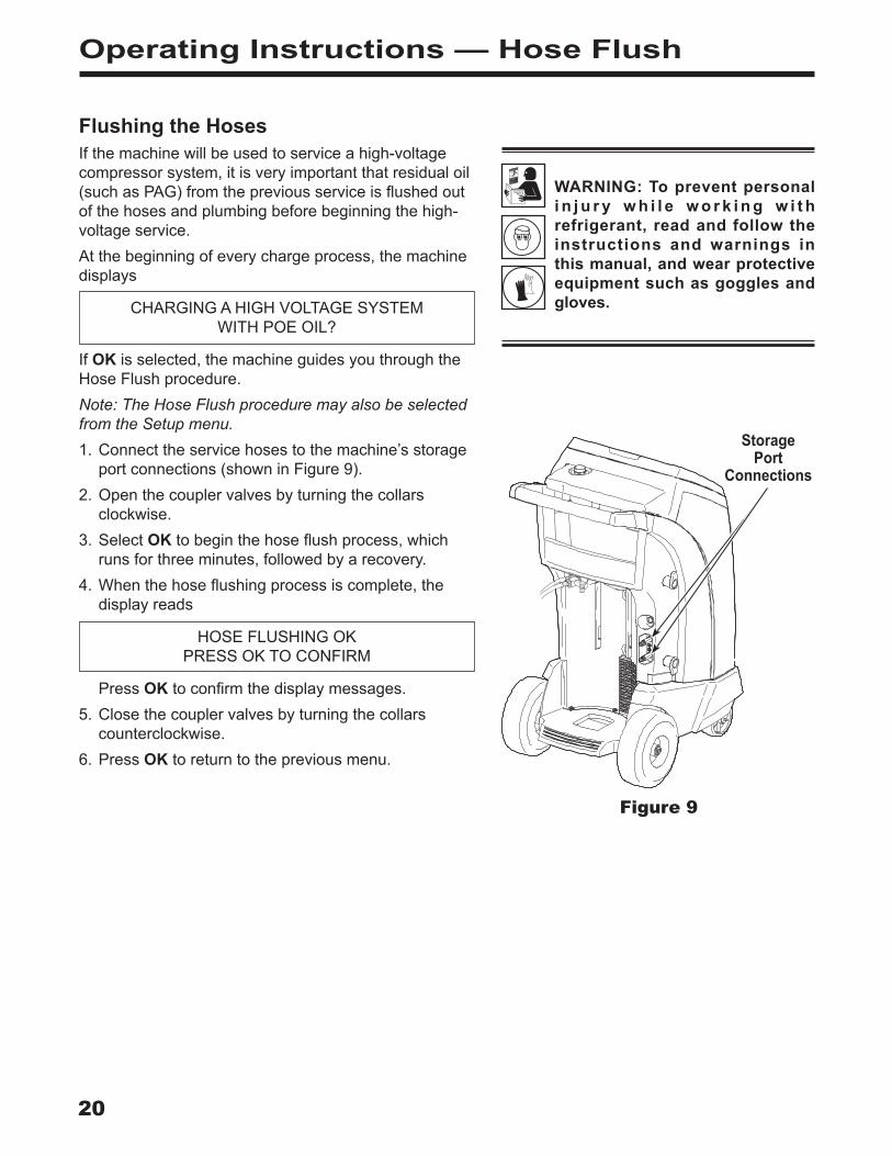
IfOKisselected,themachineguidesyouthroughtheHoseFlushprocedure.Note: The Hose Flush procedure may also be selected from the Setup menu.1.Connecttheservicehosestothemachine’sstorage
portconnections(showninFigure9).2.Openthecouplervalvesbyturningthecollars
clockwise.3.SelectOK tobeginthehoseflushprocess,which
runsforthreeminutes,followedbyarecovery.4.Whenthehoseflushingprocessiscomplete,the
displayreads
HOSEFLUSHINGOKPRESSOKTOCONFIRM
PressOKtoconfirmthedisplaymessages.5.Closethecouplervalvesbyturningthecollars
counterclockwise.6.PressOK toreturntothepreviousmenu.
Figure 9
Storage Port
Connections

21AC1234-6 Rev. C
Recharge the Vehicle A/C SystemThefollowingtestsareautomaticandperformedasrequiredbySAEJ2843:
• vacuumthatruns5–20minutestoachievethecorrectlevel
• 5-minutevacuumrisetest• 15%charge• manualleaktestusingaleakdetectorcertifiedto
SAEJ2913Notes:
• J2843 leak testing is intended to find a gross leak before charge, for safety reasons. It is not intended to take the place of other established leak test practices.
• The 15% charge is automatically recovered before recharging the programmed amount.
• To avoid false failures, the temperatures of the vehicle system and the recovery machine should be within ± 5 degrees C.
Refertothevehicleservicemanualforspecificvehicleinstructions.
1.Connectservicehosestothevehicle’sserviceportsandopenthecouplers.
2.PressCHARGE . 3.ThemachinedisplaysaVINentryscreen.Tostore
vehicleservicedatabyVIN,usethearrowkeystoselectafield,usethevirtualkeypadtoenterinformation,andpressOK .
EnteringaVINisoptional;pressOKtoskipthisstepandnotactivatetheStoredDatafeature.
4.Themachinedisplays
Operating Instructions — Charge
Usethenumberkeysonthekeypadtomakeselections1–3forthevehicleA/Csystem.Forselection7,enteravalueandpressOK .
WARNING: To prevent personal i n j u r y w h i l e w o r k i n g w i t h refrigerant, read and follow the instructions and warnings in this manual, and wear protective equipment such as goggles and gloves.
HPLP
HP + LP
Refrigerant
1237 0.590 kg

22
Operating Instructions — Charge
5. Themachinedisplays
CHARGINGAHIGHVOLTAGESYSTEMTHATUSESPOEOIL?
IfOKisselected,themachinepromptsforaHoseFlushprocedure.Connecthigh-side(red)andlow-side(blue)servicehosestothestorageports,andopenthecouplervalves.PressOK.IfESCisselected,themachinecontinueswithCHARGE .
6. AfterHoseFlushiscomplete,moveservicehosestothevehicle’sserviceportsandopenthecouplers.PressOK.ThemachineperformsautomatictestsonthesystemasrequiredbySAEJ2843.
7. Whenprompted,performamanualleaktestusingaleakdetectorcertifiedtoSAEJ2913.Oncetheleaktesthasbeencompleted,CHARGEcontinues.
Movingorbumpingthemachineatthispointmayresultinaninaccuratecharge.Whenthechargecyclegetsclosetothedesiredweightvalue,themachineslowsdown.Itwillcharge,settle,chargeagain,settle,etc.
8. AttheendofCHARGE,themachinepromptsthroughaDiagnosticPressurestest.
9. FollowpromptstoequalizeliquidrefrigerantintothevehicleA/Csystemformaximumchargeaccuracy.
10.Whenprompted,closethecouplervalvesandremovetheservicehosesfromtheA/Csystem.Installthehosesonmachine’sstorageports.
11.PressOKtobeginclearinghosestopreparethemachineforthenextservice.
12.Whenthehosesareclear,thedisplayshowsasummaryofchargeresults,whichmaybeprintedbypressingOK .
Note: If a VIN was entered when prompted, complete service results may be printed at the end of the vehicle’s entire service by selecting the vehicle VIN from the STORED DATA menu.
The STORED DATA menu is found by pressing MENU and choosing FUNCTIONS.
ThevehicleA/Csystemisnowreadyforuse.
Charge continued
CAUTION: If the low-side (blue) or high-side (red) coupler valve is left open during the hose clearing process, the system will pull refrigerant back out of the vehicle.
Note: The charge process includes an automatic vacuum leak test, after which the system is pressurized with a small amount of refrigerant for a manual leak test.
• If the leak test passes, the refrigerant is automatically recovered and the selected charge is added.
• If the leak test fails, the refrigerant needs to be recovered and the vehicle needs to be checked for leaks by using an electronic leak detector.
23AC1234-6 Rev. C
Operating Instructions — Automatic
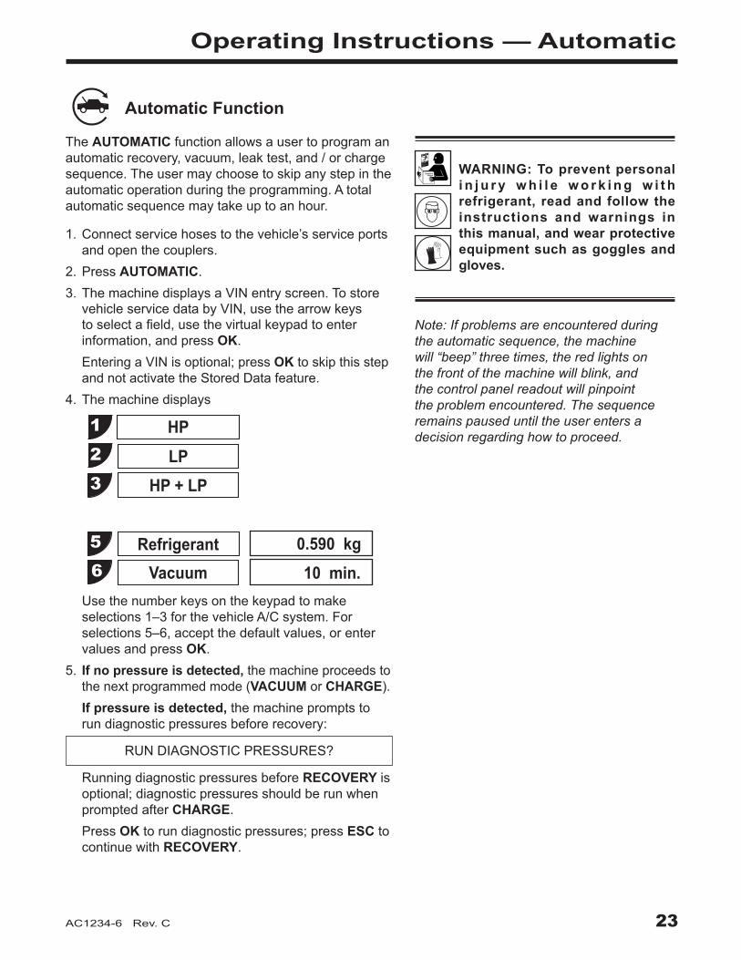
WARNING: To prevent personal i n j u r y w h i l e w o r k i n g w i t h refrigerant, read and follow the instructions and warnings in this manual, and wear protective equipment such as goggles and gloves.
Automatic Function
The AUTOMATICfunctionallowsausertoprogramanautomaticrecovery,vacuum,leaktest,and/orchargesequence.Theusermaychoosetoskipanystepintheautomaticoperationduringtheprogramming.Atotalautomaticsequencemaytakeuptoanhour.
Usethenumberkeysonthekeypadtomakeselections1–3forthevehicleA/Csystem.Forselections5–6,acceptthedefaultvalues,orentervaluesandpressOK .
5 . If no pressure is detected,themachineproceedstothenextprogrammedmode(VACUUMorCHARGE).
If pressure is detected,themachinepromptstorundiagnosticpressuresbeforerecovery:
RUNDIAGNOSTICPRESSURES?
RunningdiagnosticpressuresbeforeRECOVERY isoptional;diagnosticpressuresshouldberunwhenpromptedafterCHARGE .
PressOKtorundiagnosticpressures;pressESCtocontinuewithRECOVERY .
1.Connectservicehosestothevehicle’sserviceportsandopenthecouplers.
2.PressAUTOMATIC . 3.ThemachinedisplaysaVINentryscreen.Tostore
vehicleservicedatabyVIN,usethearrowkeystoselectafield,usethevirtualkeypadtoenterinformation,andpressOK .
EnteringaVINisoptional;pressOKtoskipthisstepandnotactivatetheStoredDatafeature.
4.Themachinedisplays
HPLP
HP + LP
RefrigerantVacuum
123
56
0.590 kg10 min.
Note: If problems are encountered during the automatic sequence, the machine will “beep” three times, the red lights on the front of the machine will blink, and the control panel readout will pinpoint the problem encountered. The sequence remains paused until the user enters a decision regarding how to proceed.

24
Operating Instructions — Automatic
6. IfOKwasselected,followpromptstostartthevehicleandsettheA/CsystemaccordingtoservicemanualA/Cperformancetestrequirements.PressOKafterpressurestabilizes.PressOKagaintoprintdata;pressESCtocontinuewithRECOVERY .
7. ThemachinecheckstherefrigerantinthevehicletoverifyitisR1234yfandnotcontaminated,whichisrequiredbySAEJ2843.Themachinedisplaysthefollowingscreens:
WARMUPCALIBRATIONINPROGRESS
GASIDENTIFY REFRIGERANTPURITYACCEPTABLE
Ifthepurityreadingisacceptable,themachineperformsarecovery,andsystemoilisdrainedattheend.Ifvacuumtimewasprogrammed,themachineperformsavacuum.
8. IfCHARGEwasselected,themachinedisplays
CHARGINGAHIGHVOLTAGESYSTEMTHATUSESPOEOIL?
IfESCisselected,themachinecontinueswithCHARGE.IfOKisselected,themachinepromptsforahoseflushprocedure.Connecthigh-side(red)andlow-side(blue)servicehosestostorageportsonthemachine.Opencouplervalves.PressOK .
9. Reconnectservicehosestothevehicle’sA/Csystem.Opencouplervalves.PressOK . The machineperformsautomatictestsonthesystemasrequiredbySAEJ2843.
10.Whenprompted,performamanualleaktestusingaleakdetectorcertifiedtoSAEJ2913.Oncetheleaktesthasbeencompleted,CHARGEcontinues.
11.AttheendofCHARGE,themachinepromptsthroughaDiagnosticPressurestest.
12.FollowpromptstoequalizeliquidrefrigerantintothevehicleA/Csystemformaximumchargeaccuracy.
13.Whenthesequenceiscomplete,closethehigh-side(red)andlow-side(blue)couplervalves.
14.Whenprompted,removeservicehosesfromtheA/Csystemandinstallthemonthemachine’sstorageports.SelectOKtobeginclearinghoses.Thispreparesthemachineforthenextservice.
15.Themachinedisplaysasummaryofactionsperformedduringtheautomaticsequence.
Automatic continued
CAUTION: If the low-side (blue) or high-side (red) coupler valve is left open during the hose clearing process, the system will pull refrigerant back out of the vehicle.
Note: Diagnostic pressures will be available for printing only until the end of the Automatic function unless a VIN was entered in Step 3.
25AC1234-6 Rev. C
Operating Instructions — System Flush
System Flushing ProcessThismachineprovidesamethodofremovingoilbyforcingliquidrefrigerantthroughanA/Csystem,orcomponentsofanA/Csystem.Aspecialflushingadapter(purchasedseparately)accessestheA/Csystematthecompressorblock.Afterflushing,therefrigerantisrecoveredbythemachineandfilteredbytherecyclingcircuit,returningittoSAEpuritylevels.A/Csystemsvaryandmayrequiretheadaptingandflushingofindividualcomponents.Refertoservicebulletinsasneededduringthisprocedure.
Notes:
• The machine must have at least 4.5 kg (10 lbs.) of refrigerant available in the ISV (as indicated on the display) for charging.
• If the flush process is interrupted by an accidental power-down or other fault, use the Recovery mode to remove the refrigerant from the vehicle.
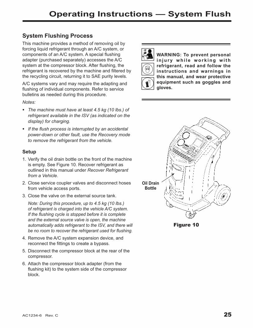
Setup1.Verifytheoildrainbottleonthefrontofthemachine
isempty.SeeFigure10.RecoverrefrigerantasoutlinedinthismanualunderRecover Refrigerant from a Vehicle .
2.Closeservicecouplervalvesanddisconnecthosesfromvehicleaccessports.
3.Closethevalveontheexternalsourcetank.
Note: During this procedure, up to 4.5 kg (10 lbs.) of refrigerant is charged into the vehicle A/C system. If the flushing cycle is stopped before it is complete and the external source valve is open, the machine automatically adds refrigerant to the ISV, and there will be no room to recover the refrigerant used for flushing.
4.RemovetheA/Csystemexpansiondevice,andreconnectthefittingstocreateabypass.
5.Disconnectthecompressorblockattherearofthecompressor.
6.Attachthecompressorblockadapter(fromtheflushingkit)tothesystemsideofthecompressorblock.
Figure 10
Oil Drain Bottle
WARNING: To prevent personal i n j u r y w h i l e w o r k i n g w i t h refrigerant, read and follow the instructions and warnings in this manual, and wear protective equipment such as goggles and gloves.

26
Operating Instructions — System Flush
WARNING: Do NOT disconnect service couplers during the flushing process. Refrigerant could spray out of the fittings, and exposure may cause personal injury.
7.Configuretheblockconnectorstoprovideforward-orback-flushingoftherefrigerant,whichflowsfromthemachinethroughtheredhigh-sideconnectionhose.Opentheredservicecoupler.
8.Connectthefilterhousingtothedesiredreturnsideoftheadapterblockandtothebluelow-sidehose.Opentheblueservicecoupler.
9.Verifythataflushingfilteriscorrectlyinstalledintheflushingfilterhousing.Opentheisolationvalveonthehose.
Operating Instructions1.SelectSYSTEM FLUSHfromtheRRRmenu.See
Figure11.2.ThemachinedisplaysaVINentryscreen.Tostore
vehicleservicedatabyVIN,usethearrowkeystoselectafield,usethevirtualkeypadtoenterinformation,andpressOK .
EnteringaVINisoptional;pressOKtoskipthisstepandnotactivatetheStoredDatafeature.
3.SelectSTART toacceptthedefaultflushtimeof10minutes,orenterthedesiredflushtimeusingthekeypadandselectSTART.
4.ThevacuumpumprunsforfiveminutestoremoveairfromtheA/Csystem,ifneeded.
5 . Themachineflushesthesystemforthedesignatedlengthoftime,andthenentersarecoverymode.
6.Oilthathasbeencollecteddrainsintothegraduatedoildrainbottle.Removethebottleandmeasureoil.
Disposeofoilaccordingtothelawsinyourjurisdiction.Itistheresponsibilityoftheusertodetermineifamaterialisahazardouswasteatthetimeofdisposal.
7.WhenthemachinedisplaysFLUSHCOMPLETE,closeservicecouplers,removehoses,andreassemblethevehicle’sA/Csystemtoitsoriginalstate.
8.Openthevalveonthesourcetank.9.Evacuateandrechargethevehicleaccordingtothe
instructionsinthismanual.
Operating TipsIf the external flushing filter is plugged, the unit displays
SYSTEMFLUSHPOSSIBLECLOGGEDFLUSHFILTER
ORCLOSEDCOUPLERVALVE ESCTORECOVERREFRIGERANT
PRESSOKTORETRYAfter the filter is cleared or replaced, restart System Flush from the menu shown in Figure 11.
CAUTION: To prevent vehicle damage, use an oil inject tool to replace the system oil. Flushing removes all oil from the system except what remains in the compressor.
12345
RecoveryVacuumCharge
Automatic
Esc
Figure 11The RRR Menu
Diagnostic Pressures6System Flush
È

27AC1234-6 Rev. C
Maintenance
WARNING: To prevent personal injury,• Only qualified personnel may
perform inspections and repairs to this machine.
• Read and follow the instructions and warnings in this manual, and wear protective equipment such as goggles and gloves.
• Do not operate the machine when the shroud has been removed.
General MaintenanceWipeoffthemachineoftenusingacleanclothtoremovegreaseanddirt.Periodicallycheckhosesandconnectionsforleakage.UseaJ2913electronicleakdetectortocheckfittingswhentheunithasbeendisconnectedfromitspowersourceandtheshroudhasbeenremoved.Ifyoudetectaleakthatyoucan’trepair,contactaRobinairauthorizedservicecenter.
Electrical ProtectionThemachineisequippedwithafuselocatedinsidethefrontshroud.Trytodeterminethecauseofthefusefailure,suchasanincorrectpowersourceoranextensioncordthatistoolong.1.Disconnectthemachinefromitspowersource.2.Removetheoildrainbottle.3.RemovethefourscrewsshowninFigure12,and
removetheshroud.4.Locatethefuseonthecentersheetmetal.Replace
thefusewiththesameamperageandtype.5.Replacetheshroudandtheoilbottle.
Tank Fill Adjustment Themaximumsettingfortankfillis6.8kg(15lbs.).Thisvaluemaybeadjustedtosuittheapplication.Theminimumvalueis1.8kg(4lbs.).
1.SelectTANK FILL ADJUSTMENTfromtheSetupmenu.
2.Themachinedisplaysthedefaultamountofrefrigerant:
TANKLEVEL4.5KG
3.SelectOKtoacceptthedefaultamount,orusethekeypadtoenteranamountandselectOK. Figure 12
Remove the four screws holding the shroud.

28
Maintenance
Tank FillingThismenuitemisusedtotransferrefrigerantfromasourcetanktotheISV.ThisprocedureworksonlyiftheISVcontainslessthanthemaximumamountofrefrigerantprogrammedunderTankFillAdjustment.(Seepreviouspage.)Note: If a source tank is connected to the tank fill hose while the machine is sitting idle, the machine automatically adds refrigerant up to the level set during Tank Fill Adjustment.1.ConnectanR1234yfsourcetanktothetankfillhose
attherearofthemachine.Note: The tank fill hose and the tank access port have left-hand threads. Handtightenthetankfillhose.
2.Openthetankvalve.3.Mountthesourcetankontheshelfattherearofthe
machine,orientedtosupplyliquidrefrigeranttotheconnection.Tightentheholdingstraparoundthesourcetank. Verifythetankdoesnotrestrictairflowfromthevent.
4.SelectTANK FILLINGfromtheFunctionsmenu.Themachinedisplays
FILLAMOUNTXX .XXX
CONNECTSOURCETANKTOFILLHOSE
5.PressOK.ThemachinecheckstherefrigerantinthesourcetanktoverifyitisR1234yfandnotcontaminated.Themachinedisplaysthefollowingscreens:
WARMUPCALIBRATIONINPROGRESS
GASIDENTIFYREFRIGERANTPURITYACCEPTABLE
andafterfivesecondsbeginsfillingtheinternalstoragevessel(ISV).
6.Themachineautomaticallystopswhenthepresettankfilllevelisreached.Tostopthetankfillbeforethepresetlevelisreached,selectESC .
7. Ifusinganon-refillabletank,themachinemustdisplaySOURCETANKEMPTYbeforethetankmaybediscarded.
Tank Fill Hose
Figure 13
29AC1234-6 Rev. C
Maintenance
Tank Fill Hose Filter ServiceThetankfillhoseattherearofthemachine(seeFigure13)containsafilterthatcanbecleanedwhenitappearsthatrefrigerantflowisrestricted.Whenthemachinesenseslowflow,itmaydisplayoneofthefollowingmessages:
• SOURCETANKEMPTY,butyetyouknowthesourcetankcontainsrefrigerant,connectionsaresecure,andthesourcetankvalveisopen.
• REPLACEIDENTIFIERFILTER,butyetyouknowtherefrigerantidentifierfilterisnotrestricted,thesourcetankcontainsrefrigerant,connectionsaresecure,andthesourcetankvalveisopen.
Thecausemaybethatthetankfillhosefilterisplugged.
Cleaning the Tank Fill Hose Filter1. Firstensurethatpressuredoesnotexistinthe
line.Disconnecttheexternalsourcetank,andperformamanualtankfilltocaptureanyrefrigerantintheline.
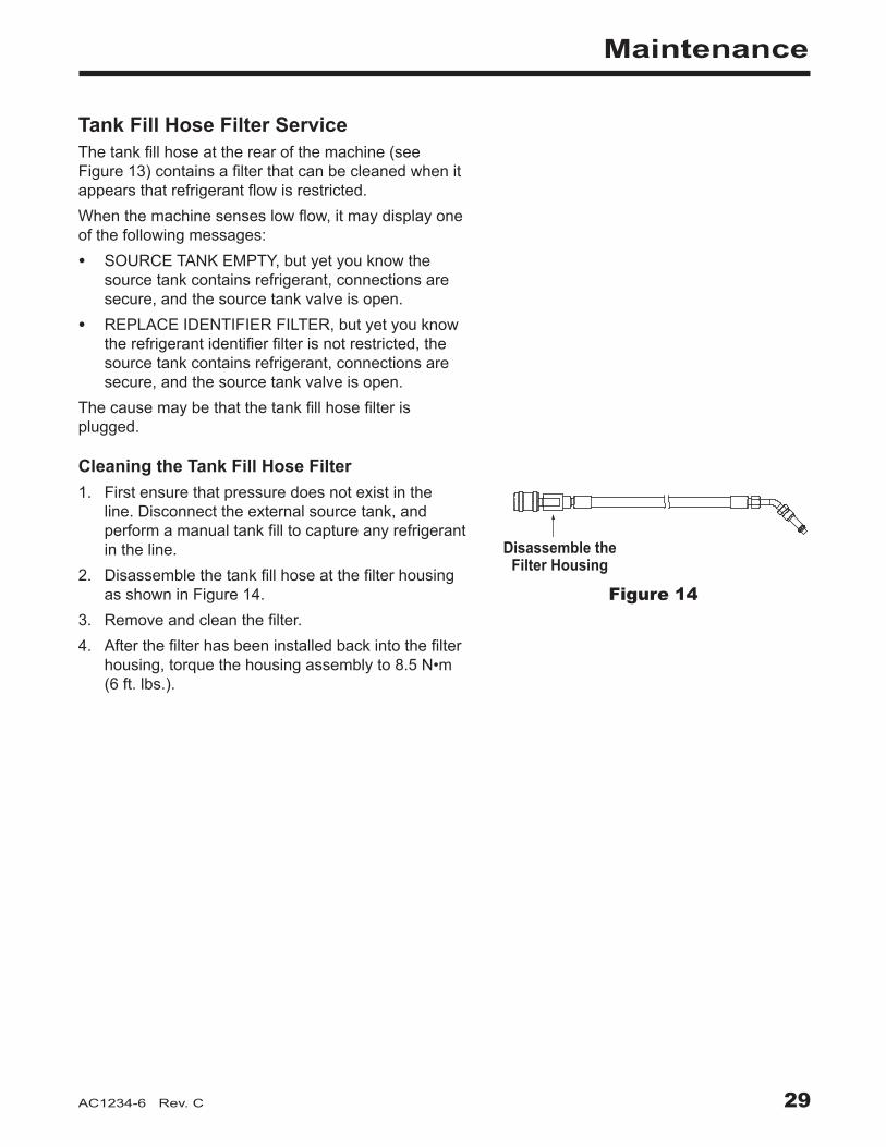
2. DisassemblethetankfillhoseatthefilterhousingasshowninFigure14.
3. Removeandcleanthefilter.4. Afterthefilterhasbeeninstalledbackintothefilter
housing,torquethehousingassemblyto8.5N•m(6ft.lbs.).
Disassemble theFilter HousingFigure 14
Disassemble the Filter Housing

30
Maintenance
Caution: To prevent equipment damage, use only authentic Robinair No. 34724 filters in this machine. All performance tests and claims are based on using this specific filter.
WARNING: To prevent personal injury while working with refrigerant, read and follow the instructions and warnings in this manual, and wear protective equipment such as goggles and gloves.
Filter ChangeThefilterisdesignedtotrapacidandparticulates,andtoremovemoisturefromrefrigerant.Tomeetthemandateforadequatemoistureandcontaminantremoval,thefiltermustbereplacedafter150kg(331lbs.)ofrefrigeranthasbeenfiltered.Themachinegivesawarningwhen100kg(220lbs.)ofthefiltercapacityhasbeenused;themachinelocksdownwhenthe150kg(331lb.)filtercapacityhasbeenreachedandwillnolongerfunction.
WARNING: The components in the machine are under high pressure. To prevent personal injury, change the filter only when the machine prompts.
Check Remaining Filter Capacity1.SelectFILTER CHANGEfromtheSetupMenuor
whenthemachineprompts.Themachinedisplays
FILTERLIFETIME:X.XXKGREPLACEFILTER?
Themachinedisplaystheamountoffiltercapacityremaininguntilthemachinelocksdown.
2.Whenprompted,selectOKtochangethefilter;selectESC toresumeusingthemachine.
Replace the Filters and Sample Hose Assembly1. IfOK wasselectedtochangethefilter,themachine
clearsthefilter,thenpromptsforthenewfiltercodetobeentered.
WAITINGFORFILTERTOBECLEARED SERIALNR.FILTER
UsethekeypadtoentertheserialnumberthatappearsonthenewfilterandselectOK.IfSERIALNUMBERWRONGisdisplayed,theserialnumberhasbeenincorrectlyentered,orthefilterhasalreadybeenusedinthismachine.
2.Themachinedisplays
TURNUNITOFF REMOVESHROUDANDREPLACEFILTER,
IDENTIFIERFILTER,AND IDENTIFIERSAMPLEHOSE
Shutoffthemachine.Removetheoilbottle.Removethefourscrewsholdingtheshroud.SeeFigure15.
Figure 15
Remove the four screws holding the shroud.

31AC1234-6 Rev. C
Maintenance
3.HangtheshroudonthebackofthemachineasshowninFigure16.
4.Removethefilterbyturningitcounterclockwise(asviewedfromthebottomofthefilter).
5.Lookatthenewfilter—verifybotho-ringsarelubricatedandcorrectlylocatedinthegroovesasshowninFigure17.
6. Installthenewfilterbythreadingitclockwiseintoplace.VerifythefilterispositionedcorrectlyasshowninFigure18.Tightenthefilterto20N•m.
Filter Change continues on next page
Filter Change continued
O-rings
Figure 17
9
STOP
ESC
OKHELP
MENU
Figure 16
Filter Hang Shroud
Here
Figure 18
Assembled Correctly
Assembled Incorrectly

32
Maintenance
Refrigerant IdentifierTherefrigerantidentifiersamplesrefrigerantgoingintotheISVtoverifyitisR1234yfandthatitisnotcontaminated.Replacethesamplehoseassemblyduringeveryfilterchangeandalsoifpromptedbyanerrormessagesayingthehoseisclogged.SeeFigure19.7. Disconnecttheexistingsamplehoseassembly
betweenthesolenoidandtherefrigerantidentifier,andinstallanewsamplehoseassembly.
Note: If the filter is any color but white, the filter needs to be replaced.
8. Pullthefilteroutofthebracketswhileremovingthebarbsfromtherubberconnectors.
9. Installanewfilterwiththearrowpointingupwardasshown.Pushthefilterbarbsintotherubberconnectors.
10.InstalltheshroudonthemachineandswitchthepowerON.
Magnet
Figure 20
Calibration CheckThisfunctionisusedtoensurethemachine’sinternalscaleisalwayscalibrated.Duringthistest,useonlythecalibrationweightthatisprovidedwiththemachine.1.SelectCALIBRATION CHECKintheSetupmenu.
Themachinedisplays
PLACESAMPLEWEIGHTONSCALE PRESSOKTOTESTPRESSESCTOQUIT
2.RefertoFigure20,andverifythemagnetonthebottomofthemachineisclean.
3.Attachthecalibrationweighttothemagnetonthebottomofthemachine.SelectOK .
• Ifthedisplayshows
PROCEDURECOMPLETED
thescaleisincalibration.SelectOK .
• Ifthedisplayshows
CALIBRATIONREJECTED!
thescaleisoutofcalibration.ContactanauthorizedRobinairservicecenterforassistance.
4.Removethecalibrationweightfromthescale.
Refrigerant Identifier
Install new filter with arrow ↑ positioned as shown.
Barb
Figure 19Replace the sample hose assembly
during every filter change.
Sample Hose Assembly
33AC1234-6 Rev. C
Maintenance
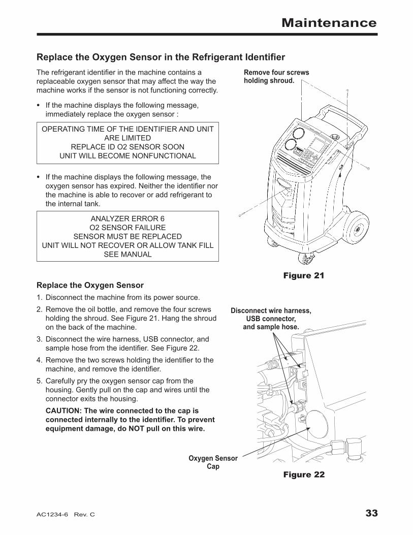
Replace the Oxygen Sensor in the Refrigerant Identifier
Figure 21
Remove four screws holding shroud.
Therefrigerantidentifierinthemachinecontainsareplaceableoxygensensorthatmayaffectthewaythemachineworksifthesensorisnotfunctioningcorrectly.
• Ifthemachinedisplaysthefollowingmessage,immediatelyreplacetheoxygensensor:
OPERATINGTIMEOFTHEIDENTIFIERANDUNITARELIMITED
REPLACEIDO2SENSORSOONUNITWILLBECOMENONFUNCTIONAL
• Ifthemachinedisplaysthefollowingmessage,theoxygensensorhasexpired.Neithertheidentifiernorthemachineisabletorecoveroraddrefrigeranttotheinternaltank.
ANALYZERERROR6O2SENSORFAILURE
SENSORMUSTBEREPLACEDUNITWILLNOTRECOVERORALLOWTANKFILL
SEEMANUAL
Replace the Oxygen Sensor1.Disconnectthemachinefromitspowersource.2.Removetheoilbottle,andremovethefourscrews
holdingtheshroud.SeeFigure21.Hangtheshroudonthebackofthemachine.
3.Disconnectthewireharness,USBconnector,andsamplehosefromtheidentifier.SeeFigure22.
4.Removethetwoscrewsholdingtheidentifiertothemachine,andremovetheidentifier.
5.Carefullyprytheoxygensensorcapfromthehousing.Gentlypullonthecapandwiresuntiltheconnectorexitsthehousing.
CAUTION: The wire connected to the cap is connected internally to the identifier. To prevent equipment damage, do NOT pull on this wire.
Disconnect wire harness, USB connector,
and sample hose.
Figure 22
Oxygen Sensor Cap

34
Maintenance
Replacing the Oxygen Sensor continued6. Disconnectthewireharnessattheconnectorby
pressingonthecentertab.Pulltheconnectorsapart.SeeFigure23.
7. Movethecapandharnessaside.Holdtheleadfromthesensor,anduseaflat-bladescrewdrivertounthreadandremovetheoxygensensor.SeeFigure24.
8. Removethepinkprotectivefilmfromthethreadedendofthenewoxygensensor.
9. Installthenewoxygensensor,usingthescrewdrivertothreaditintoplace.Tightenthesensorto4in.lbs.
10.Reconnecttheleadattheconnector,andtuckthewiresintotheopening.
11.Replacethecapandpushuntilit“clicks”intoplace.Installtheidentifierontothemachine,andreconnectthewireharness,USBconnector,andsamplehose.
12.Verifythewiringisnotbinding,andreplacetheshroud.
Figure 23
Press to disconnect
wire harness.
Use flat-blade screwdriver
to remove sensor.
Figure 24

35AC1234-6 Rev. C
Maintenance
Figure 25
Oil Drain Fitting
Oil Fill Cap and Port
Sight Glass
CAUTION: To prevent personal injury, do NOT operate the machine at any other time without the oil fill port cap installed, because the vacuum pump is pressurized during normal operation.
Caution: It is the responsibility of the user to monitor vacuum pump oil level and clarity. If contaminated oil is not removed from the vacuum pump and replaced, the vacuum pump will be permanently damaged.
Change Vacuum Pump Oil1.SelectCHANGE VACUUM PUMP OILfromthe
Setupmenuorwhenprompted.Thedisplayshowshowlongthevacuumpumphasoperatedsincethelastoilchange.
OILLIFETIMEXHOURSXMINUTES
CHANGEOIL?
2.PressOK.Ifthemachinedisplays
OILCHANGEWAIT...
allowthevacuumpumptorunfor30secondstowarmuptheoil.Iftheoilisalreadywarm,thedisplayshows
OILCHANGE UNITCLEARING
WAIT
whilethecompressorrunstoeliminateanypressureinthevacuumpump.
3.Afterthecompressorstops,slowlyopentheoilfillcaptoverifythereisnopressureinthemachine.Thencarefullyremovethecap.SeeFigure25.
4.Thedisplayshows
DRAINTHEUSEDPUMPOIL ATTHEENDADDABOUT150MLOFNEWOIL
PRESSOKTOCONFIRM
Removetheoildrainfittingcap,anddraintheoilintoasuitablecontainerfordisposal.Replacethecapandclosetightly.
5 . Slowlyaddapproximately150mlofvacuumpumpoiltothepumpthroughtheoilfillport.PressOK tostartthevacuumpump.
6.Thedisplayshows
POUROILINTHEPUMP UPTOTHECORRECTLEVEL
PRESSESCTOQUIT
Slowlyaddvacuumpumpoiltothepumpthroughtheoilfillportuntiltheoillevelrisestothecenterofthesightglass.
7. Installthecapontheoilfillportandclosetightly . PressESC.

36
Maintenance
Edit Print HeaderTomakechangestothetextthatappearsintheheaderoneachprintout:1.SelectGARAGE DATAfromtheSetupmenu.2.Thecursorisblinkinginthefirstfield.Pressthe
Menukeytodisplayavirtualkeyboard.3.Usethearrowkeystomovearoundthekeyboard.
PressOKtoenteracharacter.4.PresstheMenukeytoexitthekeyboardandmove
tothenextfillfield.5.PressOKtosavethedataandpressESCtoexitthe
keyboard.ThisprocedureisexplainedinmoredetailintheSetupsectionofthismanualunderGarageData.
Replace Printer PaperToinstallanewpaperrollintheprinter:1.Removethecoverontheprinterbypullingouton
thetabasshowninFigure26.2.Removethepapercore.3. Installthenewrollofpaperwiththeendofthepaper
atthetopoftheroll.4.Assemblethecoverontotheprinterwiththeleading
edgeofthepaperovertheroller.
Tab
Leading Edge of Paper Over Roller
Figure 26Replace Service Hoses and / or Service CouplersEnsurepressurehasbeenremovedfromservicehosesbeforedisconnectingahoseorcouplerfromthemachine.Pressuregaugesmustreadatorbelow0psig.Ifpressureexists,recovertherefrigerantfromthehosesbeforedisconnectingahoseorcoupler.

37AC1234-6 Rev. C
Component Replacement Part No.CalibrationWeight 16214ContaminatedRefrigerantTank(optional) 17990Filter 34724FilterMaintenanceKit 13172 (includes filter and vacuum pump oil)IdentifierFilter 16913IdentifierOxygenSensor 16916IdentifierSampleHoseAssembly 16106OilDrainBottle 19100PrinterPaper(1roll) 34214ServiceCoupler,High-Side(red) 18123ServiceCoupler,Low-Side(blue) 18122ServiceCouplerSet 18124 (high-side [red] and low-side [blue)] couplers) ServiceHose(low-side, blue) 70123ServiceHose(high-side, red) 70124ServiceHoseSet 71234 (high-side [red] and low-side [blue)] hoses)TankFillHoseFilter 10233VacuumPumpOil(quart) 13203VacuumPumpOil(gallon) 13204VinylDustCover(optional) 17499
Parts List
CAUTION: To prevent personal injury, use only those repair parts called out in this parts list. Items found in this parts list have been carefully tested and selected by Robinair.
Replacement Parts and Glossary
Glossary
A/C System :Thevehicleairconditioningsystembeingserviced.Evacuation :Moistureandothernon-condensablesareremovedfromanA/Csystembyavacuumpumpcapableofpullingthesystemto5mbarabsolute.Internal Storage Vessel (ISV) :Therefillablerefrigerantstoragetankdesignedspecificallyforthismachine;9.09kg(20.04lb.)capacity.Leak Test (Vacuum) : Componentscontainingrefrigerantareevacuatedandmonitoredforpressurerise,whichcouldindicatealeak.Machine :ModelNo.AC1234-6.PAG : PolyalkyleneGlycolPOE : PolyesterOilRecovery / Recycling :RefrigerantisrecoveredfromanA/Csystem,filtered,andstoredintheISV.Refrigerant :R1234yf.
38
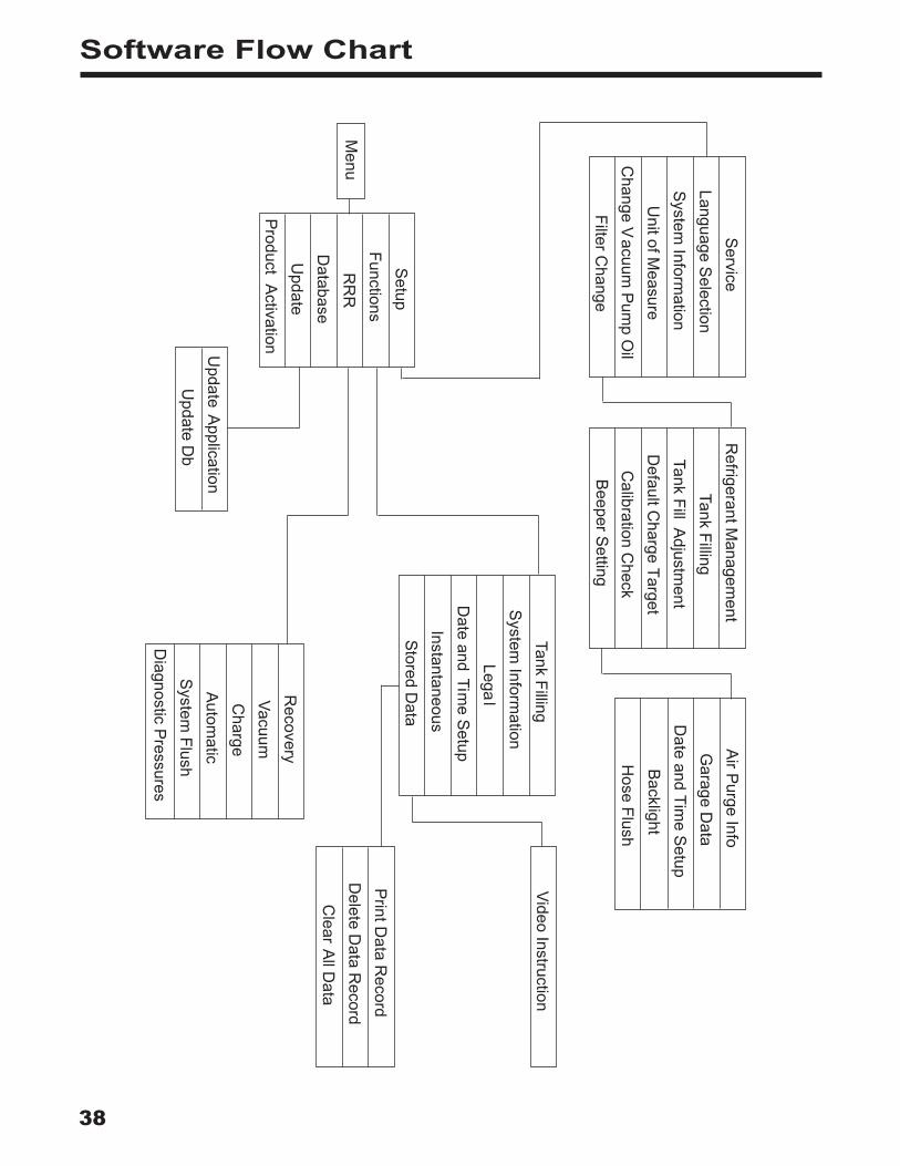
Software Flow Chart
Setup
FunctionsR
RR
DatabaseU
pdateP
roduct Activation
Menu
Service
Language Selection
System
Information
Unit of M
easureC
hange Vacuum
Pum
p Oil
Filter Change
Refrigerant M
anagement
Tank FillingTank Fill A
djustment
Default C
harge TargetC
alibration Check
Beeper S
etting
Air P
urge InfoG
arage Data
Date and Tim
e Setup
Backlight
Recovery
VacuumC
hargeA
utomatic
System
FlushD
iagnostic Pressures
Tank FillingS
ystem Inform
ationLega
lD
ate and Time S
etupInstantaneous
Stored D
ata
Update A
pplicationU
pdate Db
Print D
ata Record
Delete D
ata Record
Clear A
ll Data
Video Instruction
Hose Flush

39AC1234-6 Rev. C
Troubleshooting Messages
Display Cause Solution
AIRFLOWERROR Fanisnotworking.Airflowisblocked.
Exit current test. Contact Robinair authorized service center.
ANALYZERERROR1 UNSTABLEOUTPUT
1.Insufficientrefrigerantflowtoidentifier.
2.PossibleelectromagneticorRF(radiofrequency)interference.
1. Check source tank for pressure and secure valve connections.
2. Move unit away from EMF or RFI sources.
ANALYZERERROR2 HIGHOUTPUT
PossibleelectromagneticorRF(radiofrequency)interference.
Move unit away from EMF or RFI sources.
ANALYZERERROR3 AIRCALIBRATIONLOW
Possiblerefrigerantinexternalcalibrationair.
Check air ventilation and air flow.
ANALYZERERROR4 IDENTIFIEROUTOF
TEMPERATURERANGE
Identifiertemperatureoutsideoperatingrange.
Check unit ventilation and ambient conditions.
ANALYZERERROR5 REPLACEIDENTIFIER
FILTERANDSAMPLEHOSEASSEMBLY
1.Insufficientrefrigerantflowtoidentifier.
2.Samplehoseorfilterinsiderefrigerantidentifierispluggedorcontaminatedwithoil.
1. Check source tank for pressure and secure valve connections.
2. Follow maintenance procedure to change identifier filter and sample hose.
CHARGEINPROGRESSAIRPURGE
Non-condensablegasispresentinISVthatcouldcontaminateA/Csystem.
Before it charges, the machine purges air out of the ISV.
EMPTYSOURCETANK
1.Machinesenseslowpressure.
2.Filterintankfillhoseisplugged.
1. Check source tank for pressure and secure valve connections.
2. Refer to Tank Fill Hose Service in Maintenance section.
INSUFFICIENTPRESSURE Ifpressureislessthan0.7bar,refrigerantcannotbeidentified.
Refer to Vacuum section; follow instructions to evacuate system.
ISVCONDITIONMachineiscirculatingrefrigeranttobuildISVpressureforachargecycle.
Charge process is automatically interrupted and machine operates in a mode to build tank pressure. Once tank pressure is sufficient, machine automatically completes charge.

40
Troubleshooting Messages
Troubleshooting Messages continued
Display Cause Solution
OILOUTOFLIMITVacuumpumphasrunfor10hours;vacuumpumpoilshouldbereplaced.
Refer to Change Vacuum Pump Oil in the Maintenance section for instructions.
PRESSURETOOHIGH Excessivepressurehasbeendetected.
Press ESC. Refer to Recovery section and recover refrigerant before proceeding.
PURITYTESTFAILEDRefrigerantinvehicleiseithernotR1234yforitiscontaminated.
Refer to Troubleshooting Procedures section. Use 25700 external recovery machine to recover refrigerant.
PURITYTESTFAILED 100%AIR
1.Insufficientrefrigerantflowtoidentifier.
2.Excessiveairinsourcetank.
1. Check source tank for pressure and secure valve connections.
2. Replace source tank with good refrigerant.
REFRIGERANTINSUFF
AfterselectingCHARGEandenteringadesiredweight,iftheweightenteredwillleavelessthan.91kg(2lbs.)ofrefrigerantinISVaftercharge,chargefunctionwillnotstart.
Refer to Manually Fill the Internal Storage Vessel (ISV) in the Maintenance section.
REPLACEIDENTIFIERFILTER
1.Filterinsiderefrigerantidentifierisplugged.
2.Filterintankfillhoseisplugged.
1. Refer to Maintenance section for instructions to change identifier filter.
2. Refer to Tank Fill Hose Service in Maintenance section.
SYSTEMPRESSURETOOLOW
Ifpressureislessthan0.7bar,therefrigerantcannotbeidentified.
If vehicle is very cold, allow vehicle to warm up and retest. Otherwise enter Vacuum mode and evacuate system.
VACUUMDECAYTESTFAILED
AleakinthevehicleA/Csystem.
Exit current test and perform repairs on the vehicle A/C system.
41AC1234-6 Rev. C
Setup, Tank Fill, and Background Tank Fill Functions
Troubleshooting Procedures
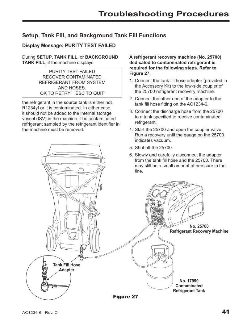
Display Message: PURITY TEST FAILED
DuringSETUP,TANK FILL,orBACKGROUND TANK FILL,ifthemachinedisplays
PURITYTESTFAILED RECOVERCONTAMINATED
REFRIGERANTFROMSYSTEM ANDHOSES.
OKTORETRYESCTOQUIT
therefrigerantinthesourcetankiseithernotR1234yforitiscontaminated.Ineithercase,itshouldnotbeaddedtotheinternalstoragevessel(ISV)inthemachine.Thecontaminatedrefrigerantsampledbytherefrigerantidentifierinthemachinemustberemoved.
A refrigerant recovery machine (No. 25700) dedicated to contaminated refrigerant is required for the following steps. Refer to Figure 27.1.Connectthetankfillhoseadapter(providedin
theAccessoryKit)tothelow-sidecouplerofthe25700refrigerantrecoverymachine.
2.ConnecttheotherendoftheadaptertothetankfillhosefittingontheAC1234-6.
3.Connectthedischargehosefromthe25700toatankspecifiedtoreceivecontaminatedrefrigerant.
4.Startthe25700andopenthecouplervalve.Runarecoveryuntilthegaugeonthe25700indicatesvacuum.
5.Shutoffthe25700.6.Slowlyandcarefullydisconnecttheadapter
fromthetankfillhoseandthe25700.Theremaystillbeasmallamountofpressureintheline .
No. 25700 Refrigerant Recovery Machine
No. 17990 Contaminated
Refrigerant TankFigure 27
Tank Fill Hose Adapter

42
Recovery Function or Automatic Function
Figure 28
Troubleshooting Procedures
Connect No. 25700 contaminated refrigerant recovery machine here.
Display Message: PURITY TEST FAILED
DuringtheRECOVERYfunctionorAUTOMATIC RECOVERYfunction,ifthemachinedisplays
PURITYTESTFAILED RECOVERCONTAMINATED
REFRIGERANTFROMSYSTEM ANDHOSES.
OKTORETRYESCTOQUIT
therefrigerantinthesourcetankorinthevehicleA/CsystemiseithercontaminatedoritisnotR1234yf.Ineithercase,itshouldnotbeaddedtotheinternalstoragevesselinthemachine.Thecontaminatedrefrigerantsampledbytherefrigerantidentifierinthemachinemustberemoved.A refrigerant recovery machine (No. 25700) dedicated to contaminated refrigerant is required for the following steps:1.Withthemachinestillconnectedtothevehicle
andthecouplersopen,connectthelow-side(blue)couplerfromthe25700tothecontaminantrecoveryportonthebackoftheAC1234-6.SeeFigure28.Openthecouplervalves.
2.Connectthedischargehosefromthe25700toatankdesignedtoreceivecontaminatedrefrigerant.
3.Startthe25700andrunarecoveryaccordingtoinstructionssuppliedwiththemachine.
4.Uponachievingavacuuminthevehicle(orperrecoverymachineinstructions),disconnectthe25700fromtheAC1234-6.
5.Clearthevehicleofresidualcontaminationaccordingtothevehiclemanufacturer’sinstructionsbeforecontinuingservice.
43AC1234-6 Rev. C
Recovery FunctionDisplay Message: SYSTEM EMPTY
Ifsystempressureisbelow0bargauge,untilpressureincreases,thedisplayreads
SYSTEMEMPTY CHECKCONNECTIONS RECOVERANYWAY?
Verifyhigh-side(red)andlow-side(blue)hosesareconnectedandcouplervalvesopen.PressOKtorecover,selectVACUUMtobypassRECOVER,orpressESCtoexit.
Display Message: Filter Weight XXX LBIf100kg(220lbs.)ormoreofrefrigeranthasbeenrecoveredsincelastfilterchange,displayreads
FILTERWEIGHTXXXLB
Tomeetrequirements,itismandatorytoreplacethefilterafter150kg(331lbs.)ofrefrigeranthasbeenfiltered.Themachinegivesawarningtoreplacethefilterwhenfilterweightreaches100kg(220lbs.);whenfilterweightreaches150kg(331lbs.),themachinelocksoutandceasestooperate.RefertoReplace the FilterintheMaintenancesection.
Display Message: Replace Identifier FilterIfthemachinedisplays
REPLACEIDENTIFIERFILTER OKTOCONFIRM
thefilterinsidetherefrigerantidentifierneedstobereplaced.PressOKtoconfirm,andrefertotheMaintenancesectionofthismanualforinstructions.
Troubleshooting Procedures
44
Vacuum FunctionDisplay Message: PRESSURE TOO HIGH
BeforethemachinebeginsevacuatingtheA/Csystem,itchecksforpressureinthesystemthatmightdamagethevacuumpump.Ifpressuregreaterthan0.7barisdetected,themachinedisplays
PRESSURETOOHIGHCHECKCONNECTIONS
SelectOK,andrecoverrefrigerantbeforeproceeding.
Display Message: Vacuum Time X:XX MinIfaleaktestwasprogrammed,andaleakisdetected,themachinedisplays
VACUUMTIMEX:XXMINLEAKTESTRESULTNEGATIVE
PressESCtoexittheautomaticsequenceandperformneededrepairs.PressOKtocontinuetheautomaticsequencedespitethefailedleaktest.Toensureanaccurateleaktest,itisimperativethatathoroughrecoveryandevacuationofthesystembeperformed.Duringtherecoveryprocess,coldspotscandevelopintheA/Csystem.PocketsofrefrigerantindesiccantandinsystemoilwillcontinuetovaporizeastheA/Csystemtemperatureequalizestowardambient.Asthisoccurs,A/Csystempressurewillincrease,whichmaybeinterpretedbythemachineasaleak.Thiswillvarysomewhatwithambienttemperatureconditions.
Troubleshooting Procedures

45AC1234-6 Rev. C
Automatic Function, System Flush, or Charge Function
Troubleshooting Procedures
Display Message: REFRIGERANT INSUFF
IftheweightenteredismorethantherefrigerantavailableintheISV,thechargefunctionwillnotstart.Thedisplayreads
REFRIGERANTINSUFF
RefertoManuallyFilltheISVintheMaintenancesection.
Display Message: PRESSURE TOO HIGH FOR VACUUM
BeforethemachinebeginsevacuatingtheA/Csystemduringtheautomaticsequence,itchecksforanypressureinthesystemthatmaydamagethevacuumpump.Ifpressureisdetected,themachinedisplays
PRESSURETOOHIGHFORVACUUM!
PressESC.Recoverrefrigerantbeforeproceeding.
Display Message: VACUUM TIME X:XX MINIfaleaktestwasprogrammed,andaleakisdetected,themachinedisplays
VACUUMTIMEX:XXMINLEAKTESTRESULTNEGATIVE
PressESCtoexittheautomaticsequenceandperformneededrepairs.PressOKtocontinuetheautomaticsequencedespitethefailedleaktest.
Display Message: PURITY TEST FAILED
RefertoTroubleshooting Procedures, Recovery Function and Automatic Function .
InformationToensureanaccurateleaktest,itisimperativethatathoroughrecoveryandevacuationofthesystemisperformed.Duringtherecoveryprocess,coldspotscandevelopintheA/Csystem.PocketsofrefrigerantindesiccantandinsystemoilwillcontinuetovaporizeastheA/Csystemtemperatureequalizestowardambient.Asthisoccurs,A/Csystempressureincreases,whichmaybeinterpretedbythemachineasaleak.Thisvariessomewhatwithambienttemperatureconditions.

46
Storage and Transportation of Equipment
StorageNeverleavethemachineliveifanimmediateuseisnotscheduled.1.Disconnectthemachinefromitspowersupply.2.Looptheservicehosesaroundthehandletwiceand
attachthemtothestorageports.SeeFigure30.3.Storethemachineinadry,stablearea,awayfrom
flamesandhotsurfaces.Thetemperatureofthestorageareashouldrangebetween-18°Cand66°C(0°Fand150°F).
4.Lockthefrontwheels.
Transportation of Equipment
WARNING: To prevent personal injury should the machine require transport to a local Robinair service center, follow local government regulations regarding transportation of equipment containing R1234yf.
Figure 29
Hose couplers connected to storage ports.

Rev. November 1, 2005This product is warranted to be free from defects in workmanship, materials, and components for a period of one year from date of purchase. All parts and labor required to repair defective products covered under the warranty will be at no charge. The following restrictions apply:1. The limited warranty applies to the original
purchaser only.2. The warranty applies to the product in
normal usage situations only, as described in the Operating Manual. The product must be serviced and maintained as specified.
3. If the product fails, it will be repaired or replaced at the option of the manufacturer.
4. Transportation charges for warranty service will be reimbursed by the factory upon verification of the warranty claim and submission of a freight bill for normal ground service. Approval from the manufacturer must be obtained prior to shipping to an authorized service center.
5. Warranty service claims are subject to authorized inspection for product defect(s).
6. The manufacturer shall not be responsible for any additional costs associated with a product failure including, but not limited to, loss of work time, loss of refrigerant, cross-contamination of refrigerant, and unauthorized shipping and/or labor charges.
7. All warranty service claims must be made within the specified warranty period. Proof-of-purchase date must be supplied to the manufacturer.
8. Use of recovery/recycling equipment with unauthorized refrigerants or sealants will void warranty.• Authorized refrigerants are listed on the
equipment or are available through the Technical Service Department.
• The manufacturer prohibits the use of the recovery/recycling equipment on air conditioning (A/C) systems containing leak sealants, either of a seal-swelling or aerobic nature.
This Limited Warranty does NOT apply if:
• The product, or product part, is broken by accident.
• The product is misused, tampered with, or modified.
• The product is used for recovering or recycling any substance other than the specified refrigerant type. This includes, but is not limited to, materials and chemicals used to seal leaks in A/C systems.
Robinair Limited Warranty Statement
Declaración de garantía limitada Robinair
Revisión del 1 de noviembre de 2005Se garantiza que este producto no posee defectos de mano de obra, materiales y componentes por el período de un año a partir de la fecha de compra. Todas las partes y mano de obra requerida para reparar los productos con defecto cubiertos bajo la garantía no tendrán costo. Aplican las siguientes restricciones:1. La garantía limitada aplica al comprador
original únicamente.2. La garantía aplica al producto en situaciones
de uso normal únicamente, como lo indica el Manual de funcionamiento. Al producto se le debe dar servicio y mantenimiento como se especifica.
3. Si falla el producto, se debe reparar o reemplazar a discreción del fabricante.
4. Los cargos de transporte de servicio de garantía serán reembolsados por la fábrica al verificar el reclamo de garantía y presentar una boleta de flete por servicio terrestre regular. Se debe obtener la aprobación del fabricante antes de hacer el envío a un centro de servicio autorizado.
5. Los reclamos de servicio de garantía están sujetos a inspección de defectos del producto.
6. El fabricante no será responsable de los costos adicionales relacionados con fallas en el producto, que incluyen pero no se limitan a, tiempo improductivo, pérdida de refrigerante, contaminación de refrigerante y envío no autorizado o cargos por mano de obra.
7. Todo reclamo de servicio de garantía se debe hacer dentro del período de garantía establecido. Se debe proporcionar la fecha de la prueba de compra al fabricante.
8. El uso de equipo de recuperación/reciclaje con refrigerantes o selladores no autorizados anula la garantía.• Los refrigerantes autorizados se indican
en el equipo o están disponibles a través del Departamento de servicio técnico.
• El fabricante prohíbe el uso de equipo de recuperación/reciclaje en sistemas de aire acondicionado (A/C) con fugas de sellador, ya sea porque un sello se infla o es de naturaleza aeróbica.
Esta garantía limitada NO aplica si:
• El producto, o parte de éste, se rompe accidentalmente.
• El producto se usa incorrectamente, se adultera o modifica.
• El producto se usa para recuperar o reciclar cualquier sustancia que sea diferente al tipo de refrigerante establecido. Esto incluye, pero no se limita a materiales y productos químicos utilizados para sellar fugas en sistemas de A/C.
Énoncé de la garantie limitée de Robinair
Révisée le 1er novembre 2005Ce produit est couvert contre les défauts de matériau, de fabrication et de composant pendant un an à compter de la date d’achat. Toutes les pièces et la main-d’œuvre nécessaires aux réparations sous garantie sont sans frais. Toutefois, les restrictions suivantes s’appliquent :1. La garantie limitée s’applique uniquement à
l’acheteur initial.2. La garantie s’applique uniquement au
produit utilisé dans des conditions de fonctionnement normales conformément au manuel d’utilisation. Il doit être réparé et entretenu conformément aux spécifications.
3. Si le produit subit une défaillance, il sera réparé ou remplacé à la discrétion du fabricant.
4. Les frais de transport pour les réparations sous garantie sont remboursés par l’usine après l’évaluation de la réclamation au titre de la garantie et après la soumission d’une facture de transport terrestre standard. L’approbation du fabricant est requise avant l’expédition du produit à un atelier de réparation autorisé.
5. Les réclamations au titre de la garantie sont sujettes à l’inspection du produit défectueux par un personnel autorisé.
6. Le fabricant ne peut être tenu responsable pour tout coût supplémentaire lié à la défaillance du produit incluant, sans toutefois s’y limiter, les interruptions de fonctionnement, la perte de liquide frigorigène, la contamination des liquides frigorigènes et l’expédition et/ou les frais de main-d’œuvre soumis par des ateliers non autorisés.
7. Toute réclamation pour des réparations au titre de la garantie doit être soumise durant la période de garantie. Une preuve d’achat doit être fournie au fabricant.
8. L’utilisation d’un appareil de récupération et de recyclage avec du liquide frigorigène ou des scellants non spécifiés annule la garantie.• Les liquides frigorigènes autorisés sont
indiqués sur l’appareil, ou ils peuvent être obtenus auprès du Service technique.
• Le fabricant interdit l’utilisation d’un appareil de récupération et de recyclage dans les systèmes de climatisation contenant des colmatants pour fuites, que ce soient des scellants à dilatation ou aérobiques.
Cette garantie limitée NE s’applique PAS si le produit :
• ou une partie du produit a été endommagé par un accident.
• a été utilisé de façon inadéquate, ou qu’il a été altéré ou modifié.
• est utilisé pour la récupération et le recyclage de substances autres que le type de liquide frigorigène spécifié. Ces substances comprennent, sans toutefois s’y limiter, les matériaux et les produits chimiques utilisés pour colmater les fuites des systèmes de climatisation.

567817 (Rev. C, November 10, 2014) © Bosch Automotive Service Solutions LLC
The Robinair unit is designed to meet all applicable agency certifications, including Underwriter's Laboratories, Inc., SAE Standards, and CUL. Certain state and local jurisdictions dictate that using this equipment to sell refrigerant by weight may not be permitted. We recommend charging for any A/C service by the job performed. This weight scale provides a means of metering the amount of refrigerant needed for optimum A/C system performance as recommended by OEM manufacturers.
La unidad Robinair está diseñada para cumplir con todas las certificaciones de agencia aplicables, incluyendo Underwriter's Laboratories, Inc., Estándares SAE y CUL. Ciertas jurisdicciones estatales y locales prescriben que el uso de este equipo para vender refrigerante por peso es posible que no sea permitido. Recomendamos que se cobre el trabajo realizado por dar servicio al aire acondicionado. Esta escala de peso proporciona un medio para medir la cantidad de refrigerante que se necesita para el rendimiento óptimo del sistema de aire acondicionado, tal como lo recomiendan los fabricantes OEM.
La machine Robinair a été conçue pour répondre à toutes les certifications applicables, y compris celles de l’organisation Underwriters Laboratories, Inc., ainsi qu’aux normes SAE et CUL. Certaines juridictions nationales et locales n’autorisent pas l’utilisation de cet équipement pour vendre du réfrigérant au poids. Nous recommandons de facturer l’entretien du système de climatisation en fonction du travail effectué. Ce poids de tarification permet de calculer la quantité de réfrigérant requise pour garantir le fonctionnement optimal du système de climatisation, conformément aux recommandations des fabricants de l’équipement d’origine.
Due to ongoing product improvements, we reserve the right to change design, specifications, and materials without notice.Debido a las constantes mejoras del producto, nos reservamos el derecho de cambiar diseño, especificaciones y materiales sin aviso.
En raison des améliorations constantes apportées à nos produits, nous nous réservons le droit de modifier la conception, les spécifications et les matériaux sans préavis.
655 EISENHOWER DRIVEOWATONNA, MN 55060-0995 USA
TECH SERVICES 800 822 5561 FAX 866 259 1241
CUSTOMER SERVICE 800 533 6127 FAX 800 322 2890
www.robinair.com