oracle® openstack - configuration guide for release 4 · and remove openstack services. the...
TRANSCRIPT
Oracle® OpenStack
Configuration Guide for Release 4.0
E90982-03February 2018

Oracle Legal Notices
Copyright © 2018, Oracle and/or its affiliates. All rights reserved.
This software and related documentation are provided under a license agreement containing restrictions on use and disclosure and are protectedby intellectual property laws. Except as expressly permitted in your license agreement or allowed by law, you may not use, copy, reproduce,translate, broadcast, modify, license, transmit, distribute, exhibit, perform, publish, or display any part, in any form, or by any means. Reverseengineering, disassembly, or decompilation of this software, unless required by law for interoperability, is prohibited.
The information contained herein is subject to change without notice and is not warranted to be error-free. If you find any errors, please report themto us in writing.
If this is software or related documentation that is delivered to the U.S. Government or anyone licensing it on behalf of the U.S. Government, thenthe following notice is applicable:
U.S. GOVERNMENT END USERS: Oracle programs, including any operating system, integrated software, any programs installed on the hardware,and/or documentation, delivered to U.S. Government end users are "commercial computer software" pursuant to the applicable Federal AcquisitionRegulation and agency-specific supplemental regulations. As such, use, duplication, disclosure, modification, and adaptation of the programs,including any operating system, integrated software, any programs installed on the hardware, and/or documentation, shall be subject to licenseterms and license restrictions applicable to the programs. No other rights are granted to the U.S. Government.
This software or hardware is developed for general use in a variety of information management applications. It is not developed or intended foruse in any inherently dangerous applications, including applications that may create a risk of personal injury. If you use this software or hardwarein dangerous applications, then you shall be responsible to take all appropriate fail-safe, backup, redundancy, and other measures to ensure itssafe use. Oracle Corporation and its affiliates disclaim any liability for any damages caused by use of this software or hardware in dangerousapplications.
Oracle and Java are registered trademarks of Oracle and/or its affiliates. Other names may be trademarks of their respective owners.
Intel and Intel Xeon are trademarks or registered trademarks of Intel Corporation. All SPARC trademarks are used under license and aretrademarks or registered trademarks of SPARC International, Inc. AMD, Opteron, the AMD logo, and the AMD Opteron logo are trademarks orregistered trademarks of Advanced Micro Devices. UNIX is a registered trademark of The Open Group.
This software or hardware and documentation may provide access to or information about content, products, and services from third parties.Oracle Corporation and its affiliates are not responsible for and expressly disclaim all warranties of any kind with respect to third-party content,products, and services unless otherwise set forth in an applicable agreement between you and Oracle. Oracle Corporation and its affiliates will notbe responsible for any loss, costs, or damages incurred due to your access to or use of third-party content, products, or services, except as setforth in an applicable agreement between you and Oracle.

iii
Table of ContentsAbout This Document ......................................................................................................................... v1 Introduction to OpenStack Configuration .......................................................................................... 1
Using the kollacli Command ....................................................................................................... 1Enabling Bash Command Completion ................................................................................. 2Using the kollacli Shell ....................................................................................................... 2Formatting Command Output .............................................................................................. 3
Using Groups to Deploy Services ............................................................................................... 3Setting Properties for Deployment Groups or Hosts ..................................................................... 5
Dealing With Variable Network Interface Names .................................................................. 7Configuring Network Interfaces for OpenStack Networks .............................................................. 8Configuring OpenStack Service Endpoints ................................................................................. 10Configuring OpenStack Service Accounts .................................................................................. 12About the OpenStack Kolla User ............................................................................................... 13
2 Openstack Service Configuration ................................................................................................... 15Barbican Key Manager Service ................................................................................................. 16Cinder Block Storage Service ................................................................................................... 17
Using LVM for Cinder Volumes ......................................................................................... 18Using External iSCSI Storage for Cinder Volumes ............................................................. 19Configuring the iSCSI Initiator Name and iSCSI Multipath .................................................. 21Using the NFS Backup Driver for Cinder Backup ............................................................... 22Using the Swift Backup Driver for Cinder Backup ............................................................... 22Using Shared Cinder Volumes (Multi-Attached) .................................................................. 22
Glance Image Service .............................................................................................................. 23Murano Application Catalog Service .......................................................................................... 24Neutron Networking Service ...................................................................................................... 24
Setting up Multiple External Network Interfaces ................................................................. 24Enabling Distributed Virtual Routing (DVR) ........................................................................ 25Enabling Neutron Agent High Availability ........................................................................... 26Neutron Plugins: Firewalls and Load Balancing .................................................................. 26
Nova Compute Service ............................................................................................................. 26Hypervisors Supported ...................................................................................................... 26Automatic Hypervisor Configuration ................................................................................... 28Introduction to Oracle VM Server ...................................................................................... 28Preparing a Compute Node .............................................................................................. 29Removing a Compute Node .............................................................................................. 30
Swift Object Storage Service .................................................................................................... 31Preparing the Storage Devices ......................................................................................... 31Building the Swift Rings .................................................................................................... 32Enabling and Configuring Swift ......................................................................................... 35
3 Additional Component Configuration ............................................................................................... 37Central Logging (Fluentd, Elasticsearch and Kibana) ................................................................. 37Ceph Storage ........................................................................................................................... 38
Ceph Storage Partitioning ................................................................................................. 39Setting up Ceph Storage .................................................................................................. 42Configuring Ceph Networks .............................................................................................. 44Adding a Ceph Node ........................................................................................................ 45Removing a Ceph OSD Node (Storage) ............................................................................ 45Removing a Ceph Mon Node (Controller) .......................................................................... 46Running Ceph Commands ................................................................................................ 47
MySQL Database ..................................................................................................................... 47Setting MySQL NDB Cluster Global Options ...................................................................... 47

Oracle® OpenStack
iv
Setting MySQL NDB Cluster Configuration Parameters ...................................................... 48Configuring the Service Databases ................................................................................... 49Backing Up and Restoring the MySQL Database ............................................................... 50
Service Endpoint High Availability (Keepalived and HAProxy) ..................................................... 55Time Synchronization (Chrony) ................................................................................................. 57
A kollacli Command Reference ......................................................................................................... 61
v
About This DocumentThis document is part of the documentation library for Oracle OpenStack Release 4.0, which is availableat:
https://docs.oracle.com/cd/E90981_01/
The documentation library consists of the following items:
Oracle OpenStack Release Notes
This document provides a summary of the new features, changes, fixed bugs, and known issues inOracle OpenStack. It contains last-minute information, which may not be included in the main body ofdocumentation, and information on Oracle OpenStack support.Read this document before you install your environment.
Oracle OpenStack Installation and Deployment Guide
This document explains how to install Oracle OpenStack and deploy OpenStack services.
Oracle OpenStack Configuration Guide
This document describes the configuration options for deploying services with Oracle OpenStack.
Oracle OpenStack Application Deployment Guide
This document describes how to set up Oracle products and deploy them using the OpenStackApplication Catalog (Murano) service.
Oracle OpenStack Licensing Information User Manual
This document provides licensing information for Oracle OpenStack.
This document was generated on 16 February 2018 (revision: 1309) .
You can get the latest information on Oracle OpenStack at:
https://www.oracle.com/linux/openstack/index.html
ConventionsThe following text conventions are used in this document:
Convention Meaning
boldface Boldface type indicates graphical user interface elements associated with anaction, or terms defined in text or the glossary.
italic Italic type indicates book titles, emphasis, or placeholder variables for whichyou supply particular values.
monospace Monospace type indicates commands within a paragraph, URLs, code inexamples, text that appears on the screen, or text that you enter.
Command SyntaxCommand syntax appears in monospace font. The dollar character ($) and number sign (#) are commandprompts. You do not enter them as part of the command. Commands that any user, including the rootuser, can run are shown with the $ prompt:
Access to Oracle Support
vi
$ command
Commands that must be run as the root user, or by a user with superuser privileges obtained throughanother utility such as sudo, are shown with the # prompt:
# command
The following command syntax conventions are used in this guide:
Convention Description
backslash \ A backslash is the Oracle Linux command continuation character. It is used incommand examples that are too long to fit on a single line. Enter the commandas displayed (with a backslash) or enter it on a single line without a backslash:
dd if=/dev/rdsk/c0t1d0s6 of=/dev/rst0 bs=10b \ count=10000
braces { } Braces indicate required items:
.DEFINE {macro1}
brackets [ ] Brackets indicate optional items:
cvtcrt termname [outfile]
ellipses ... Ellipses indicate an arbitrary number of similar items:
CHKVAL fieldname value1 value2 ... valueN
italics Italic type indicates a variable. Substitute a value for the variable:
library_name
vertical line | A vertical line indicates a choice within braces or brackets:
FILE filesize [K|M]
Access to Oracle Support
Oracle customers that have purchased support have access to electronic support through My OracleSupport. For information, visithttp://www.oracle.com/pls/topic/lookup?ctx=acc&id=info or visit http://www.oracle.com/pls/topic/lookup?ctx=acc&id=trs if you are hearing impaired.
1
Chapter 1 Introduction to OpenStack Configuration
Table of ContentsUsing the kollacli Command ............................................................................................................... 1
Enabling Bash Command Completion ......................................................................................... 2Using the kollacli Shell ............................................................................................................... 2Formatting Command Output ...................................................................................................... 3
Using Groups to Deploy Services ....................................................................................................... 3Setting Properties for Deployment Groups or Hosts ............................................................................. 5
Dealing With Variable Network Interface Names .......................................................................... 7Configuring Network Interfaces for OpenStack Networks ...................................................................... 8Configuring OpenStack Service Endpoints ......................................................................................... 10Configuring OpenStack Service Accounts .......................................................................................... 12About the OpenStack Kolla User ....................................................................................................... 13
Oracle OpenStack is based on the OpenStack Kolla project, which aims to simplify deployments by usingDocker containers to run OpenStack clouds. Oracle provides Docker images for OpenStack servicesbased on Oracle Linux 7.
In line with Docker best practices, each OpenStack service is broken down into its components (sometimesreferred to as a microservice). Ansible playbooks (based on the OpenStack Kolla-Ansible project) are usedto configure, deploy, and manage the Docker containers on a large number of hosts.
While it is possible to use the Ansible playbooks manually, Oracle OpenStack provides a command-lineinterface (the kollacli command) to make it easier to configure a deployment, and to deploy, update,and remove OpenStack services. The kollacli command is the only supported method for configuringand deploying Oracle OpenStack.
This chapter covers some of general configuration options for deploying Oracle OpenStack.
Using the kollacli CommandThis section introduces the kollacli command, and how you use it to configure and deploy OpenStackservices.
You run the kollacli command on the master node. To run kollacli commands, you must be amember of the kolla group.
The kollacli command has a set of subcommands, which are organized by the objects that theymanage.
To configure the layout of your OpenStack deployment, you perform actions on groups, hosts and services,as follows:
• The kollacli host commands manage the nodes in a deployment.
Example command: kollacli host add adds a host to the list of nodes.
• The kollacli group commands manage the associations between nodes and the OpenStackservices they run. Nodes in the same group run the same services.
Example command: kollacli group addhost adds a host to a group.
• The kollacli service commands manage the OpenStack services to add or remove them fromdeployment groups.
Enabling Bash Command Completion
2
Example command: kollacli service addgroup adds an OpenStack service to a deploymentgroup.
To configure your OpenStack deployment, you configure values for passwords and properties, as follows:
• The kollacli password commands manage the passwords for the OpenStack components.
Example command: kollacli password set sets a value for an individual password.
• The kollacli property commands manage the configuration settings for OpenStack services.
Example command: kollacli property set sets a value for a configuration property.
Once you have configured your deployment, you deploy OpenStack services with the kollacli deploycommand.
Help on how to use the kollacli command is available, as follows:
• To list all kollacli commands, use the kollacli help command.
• To list the related commands for an object, use the kollacli help object for example kollaclihelp host.
• To get help for a specific command, use the kollacli help subcommand command, wheresubcommand is the name of the command, for example kollacli host list or kollacliservice listgroups.
For a complete syntax reference for kollacli commands, see Appendix A, kollacli Command Reference.
Enabling Bash Command Completion
You can enable Bash command completion for the kollacli command, as follows:
1. Install the bash-completion package, if it is not already installed:
# yum install bash-completion
2. Use the kollacli complete command to generate the command completion function.
To display the function so you can copy and paste it into a file:
$ kollacli complete
To output the function to a file:
$ kollacli complete >/etc/bash_completion.d/kollacli
You need root privileges to write to the /etc/bash_completion.d directory.
3. Source the file to enable command completion:
$ source /etc/bash_completion.d/kollacli
Using the kollacli Shell
The kollacli shell enables you to enter several commands without having to type the kollaclicommand each time. You start the shell with the kollacli command. When you are in the kollaclishell, the prompt changes to (kollacli). From the shell prompt you can enter kollacli commands intheir short form, for example:
Formatting Command Output
3
$ kollacli(kollacli) host list(kollacli) group listhosts
In addition to the help command, the kollacli shell also supports the -h and --help options forobtaining help with kollacli commands.
To exit the kollacli shell and return to the operating system prompt, type exit, quit, or q.
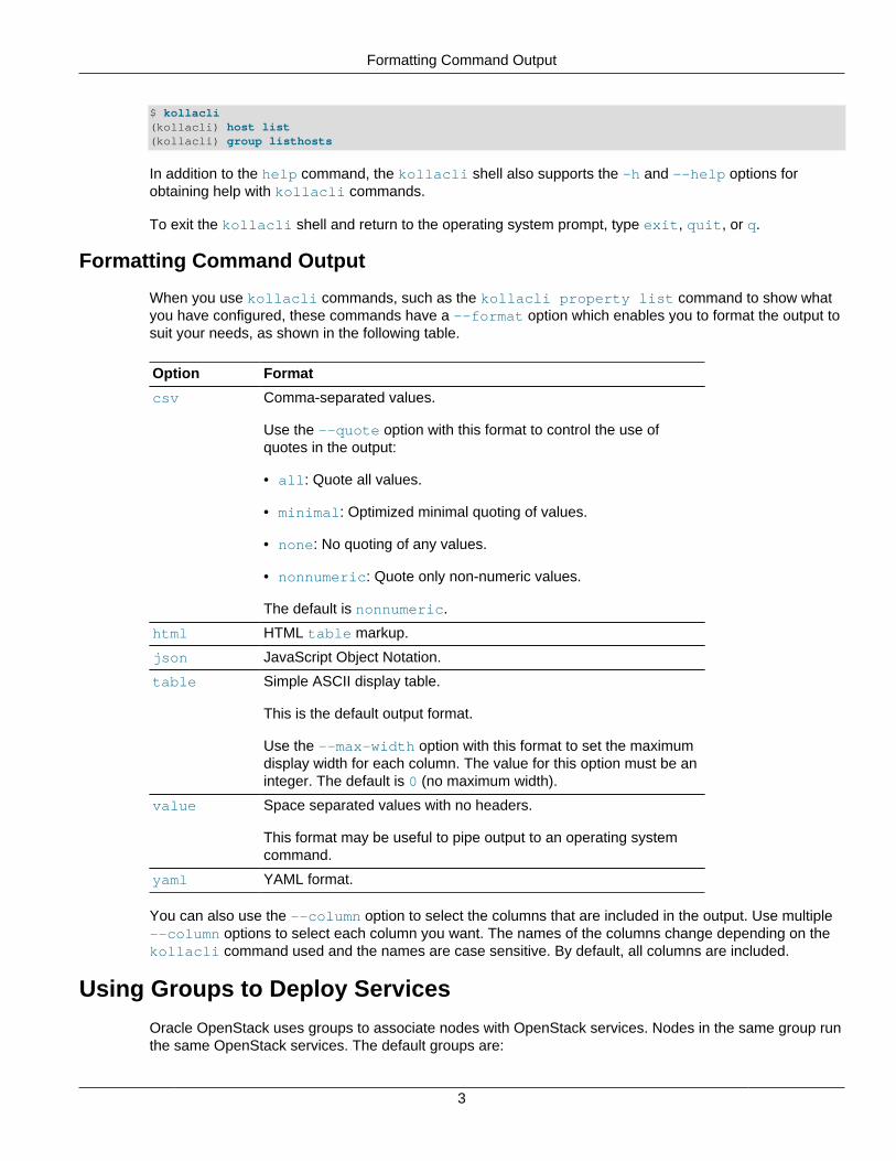
Formatting Command Output
When you use kollacli commands, such as the kollacli property list command to show whatyou have configured, these commands have a --format option which enables you to format the output tosuit your needs, as shown in the following table.
Option Format
csv Comma-separated values.
Use the --quote option with this format to control the use ofquotes in the output:
• all: Quote all values.
• minimal: Optimized minimal quoting of values.
• none: No quoting of any values.
• nonnumeric: Quote only non-numeric values.
The default is nonnumeric.
html HTML table markup.
json JavaScript Object Notation.
table Simple ASCII display table.
This is the default output format.
Use the --max-width option with this format to set the maximumdisplay width for each column. The value for this option must be aninteger. The default is 0 (no maximum width).
value Space separated values with no headers.
This format may be useful to pipe output to an operating systemcommand.
yaml YAML format.
You can also use the --column option to select the columns that are included in the output. Use multiple--column options to select each column you want. The names of the columns change depending on thekollacli command used and the names are case sensitive. By default, all columns are included.
Using Groups to Deploy Services
Oracle OpenStack uses groups to associate nodes with OpenStack services. Nodes in the same group runthe same OpenStack services. The default groups are:
Using Groups to Deploy Services
4
• control: Contains the control-related services, such as glance, keystone, ndbcluster, nova, andrabbitmq.
• compute: Contains the hypervisor part of the compute services, such as nova-compute.
• database: Contains the data part of the database services.
• network: Contains the shared network services, such as neutron-server, neutron-agents and neutron-plugins.
• storage: Contains the storage part of storage services, such as cinder and swift.
A node can belong to more than one group and can run multiple OpenStack services.
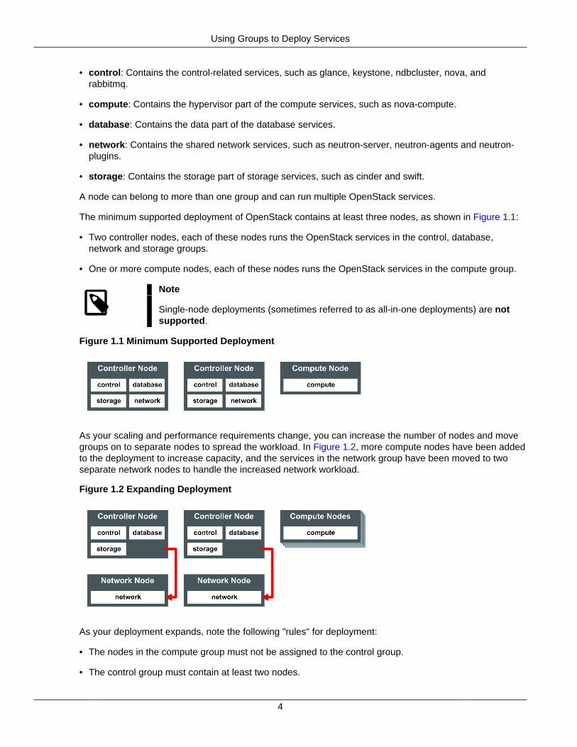
The minimum supported deployment of OpenStack contains at least three nodes, as shown in Figure 1.1:
• Two controller nodes, each of these nodes runs the OpenStack services in the control, database,network and storage groups.
• One or more compute nodes, each of these nodes runs the OpenStack services in the compute group.
Note
Single-node deployments (sometimes referred to as all-in-one deployments) are notsupported.
Figure 1.1 Minimum Supported Deployment
As your scaling and performance requirements change, you can increase the number of nodes and movegroups on to separate nodes to spread the workload. In Figure 1.2, more compute nodes have been addedto the deployment to increase capacity, and the services in the network group have been moved to twoseparate network nodes to handle the increased network workload.
Figure 1.2 Expanding Deployment
As your deployment expands, note the following "rules" for deployment:
• The nodes in the compute group must not be assigned to the control group.
• The control group must contain at least two nodes.
Setting Properties for Deployment Groups or Hosts
5
• The number of nodes in the database group must always be a multiple of two.
• The number of nodes in each group must be two or more to enable high availability.
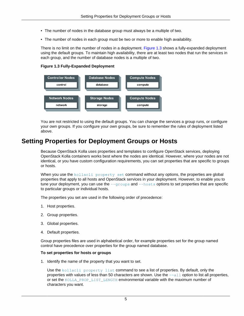
There is no limit on the number of nodes in a deployment. Figure 1.3 shows a fully-expanded deploymentusing the default groups. To maintain high availability, there are at least two nodes that run the services ineach group, and the number of database nodes is a multiple of two.
Figure 1.3 Fully-Expanded Deployment
You are not restricted to using the default groups. You can change the services a group runs, or configureyour own groups. If you configure your own groups, be sure to remember the rules of deployment listedabove.
Setting Properties for Deployment Groups or Hosts
Because OpenStack Kolla uses properties and templates to configure OpenStack services, deployingOpenStack Kolla containers works best where the nodes are identical. However, where your nodes are notidentical, or you have custom configuration requirements, you can set properties that are specific to groupsor hosts.
When you use the kollacli property set command without any options, the properties are globalproperties that apply to all hosts and OpenStack services in your deployment. However, to enable you totune your deployment, you can use the --groups and --hosts options to set properties that are specificto particular groups or individual hosts.
The properties you set are used in the following order of precedence:
1. Host properties.
2. Group properties.
3. Global properties.
4. Default properties.
Group properties files are used in alphabetical order, for example properties set for the group namedcontrol have precedence over properties for the group named database.
To set properties for hosts or groups
1. Identify the name of the property that you want to set.
Use the kollacli property list command to see a list of properties. By default, only theproperties with values of less than 50 characters are shown. Use the --all option to list all properties,or set the KOLLA_PROP_LIST_LENGTH environmental variable with the maximum number ofcharacters you want.
Setting Properties for Deployment Groups or Hosts
6
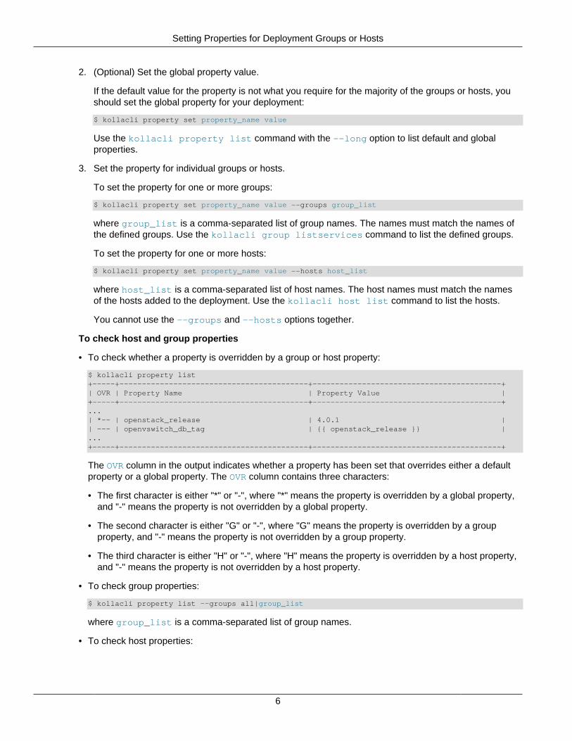
2. (Optional) Set the global property value.
If the default value for the property is not what you require for the majority of the groups or hosts, youshould set the global property for your deployment:
$ kollacli property set property_name value
Use the kollacli property list command with the --long option to list default and globalproperties.
3. Set the property for individual groups or hosts.
To set the property for one or more groups:
$ kollacli property set property_name value --groups group_list
where group_list is a comma-separated list of group names. The names must match the names ofthe defined groups. Use the kollacli group listservices command to list the defined groups.
To set the property for one or more hosts:
$ kollacli property set property_name value --hosts host_list
where host_list is a comma-separated list of host names. The host names must match the namesof the hosts added to the deployment. Use the kollacli host list command to list the hosts.
You cannot use the --groups and --hosts options together.
To check host and group properties
• To check whether a property is overridden by a group or host property:
$ kollacli property list+-----+------------------------------------------+------------------------------------------+| OVR | Property Name | Property Value |+-----+------------------------------------------+------------------------------------------+...| *-- | openstack_release | 4.0.1 || --- | openvswitch_db_tag | {{ openstack_release }} |...+-----+------------------------------------------+------------------------------------------+
The OVR column in the output indicates whether a property has been set that overrides either a defaultproperty or a global property. The OVR column contains three characters:
• The first character is either "*" or "-", where "*" means the property is overridden by a global property,and "-" means the property is not overridden by a global property.
• The second character is either "G" or "-", where "G" means the property is overridden by a groupproperty, and "-" means the property is not overridden by a group property.
• The third character is either "H" or "-", where "H" means the property is overridden by a host property,and "-" means the property is not overridden by a host property.
• To check group properties:
$ kollacli property list --groups all|group_list
where group_list is a comma-separated list of group names.
• To check host properties:
Dealing With Variable Network Interface Names
7
$ kollacli property list --hosts all|host_list
where host_list is a comma-separated list of host names.
To remove properties for groups or hosts
• To remove a group property:
$ kollacli property clear property_name --groups all|group_list
where group_list is a comma-separated list of group names.
• To remove a host property:
$ kollacli property clear property_name --hosts all|host_list
where host_list is a comma-separated list of host names.
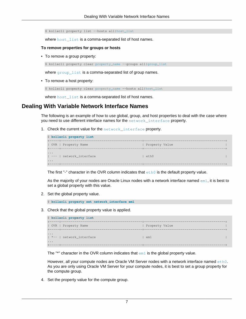
Dealing With Variable Network Interface Names
The following is an example of how to use global, group, and host properties to deal with the case whereyou need to use different interface names for the network_interface property.
1. Check the current value for the network_interface property.
$ kollacli property list+-----+------------------------------------------+------------------------------------------+| OVR | Property Name | Property Value |+-----+------------------------------------------+------------------------------------------+...| --- | network_interface | eth0 |...+-----+------------------------------------------+------------------------------------------+
The first "-" character in the OVR column indicates that eth0 is the default property value.
As the majority of your nodes are Oracle Linux nodes with a network interface named em1, it is best toset a global property with this value.
2. Set the global property value.
$ kollacli property set network_interface em1
3. Check that the global property value is applied.
$ kollacli property list+-----+------------------------------------------+------------------------------------------+| OVR | Property Name | Property Value |+-----+------------------------------------------+------------------------------------------+...| *-- | network_interface | em1 |...+-----+------------------------------------------+------------------------------------------+
The "*" character in the OVR column indicates that em1 is the global property value.
However, all your compute nodes are Oracle VM Server nodes with a network interface named eth0.As you are only using Oracle VM Server for your compute nodes, it is best to set a group property forthe compute group.
4. Set the property value for the compute group.
Configuring Network Interfaces for OpenStack Networks
8
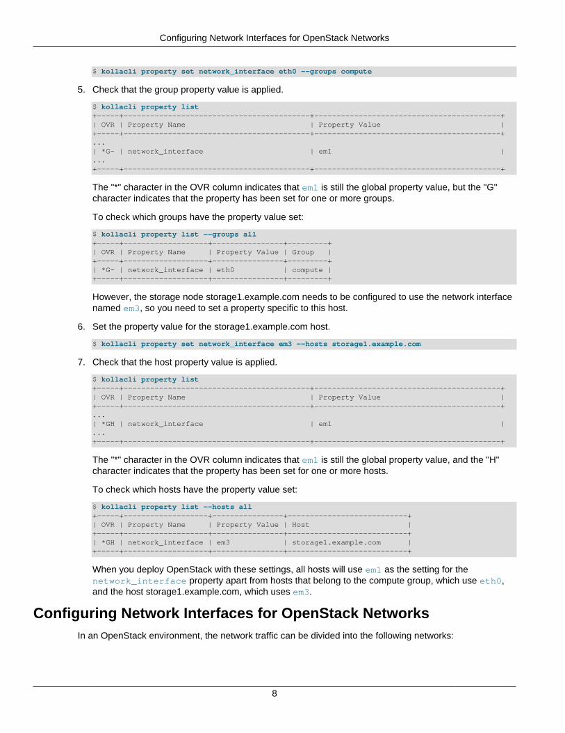
$ kollacli property set network_interface eth0 --groups compute
5. Check that the group property value is applied.
$ kollacli property list+-----+------------------------------------------+------------------------------------------+| OVR | Property Name | Property Value |+-----+------------------------------------------+------------------------------------------+...| *G- | network_interface | em1 |...+-----+------------------------------------------+------------------------------------------+
The "*" character in the OVR column indicates that em1 is still the global property value, but the "G"character indicates that the property has been set for one or more groups.
To check which groups have the property value set:
$ kollacli property list --groups all+-----+-------------------+----------------+---------+| OVR | Property Name | Property Value | Group |+-----+-------------------+----------------+---------+| *G- | network_interface | eth0 | compute |+-----+-------------------+----------------+---------+
However, the storage node storage1.example.com needs to be configured to use the network interfacenamed em3, so you need to set a property specific to this host.
6. Set the property value for the storage1.example.com host.
$ kollacli property set network_interface em3 --hosts storage1.example.com
7. Check that the host property value is applied.
$ kollacli property list+-----+------------------------------------------+------------------------------------------+| OVR | Property Name | Property Value |+-----+------------------------------------------+------------------------------------------+...| *GH | network_interface | em1 |...+-----+------------------------------------------+------------------------------------------+
The "*" character in the OVR column indicates that em1 is still the global property value, and the "H"character indicates that the property has been set for one or more hosts.
To check which hosts have the property value set:
$ kollacli property list --hosts all+-----+-------------------+----------------+---------------------------+| OVR | Property Name | Property Value | Host |+-----+-------------------+----------------+---------------------------+| *GH | network_interface | em3 | storage1.example.com |+-----+-------------------+----------------+---------------------------+
When you deploy OpenStack with these settings, all hosts will use em1 as the setting for thenetwork_interface property apart from hosts that belong to the compute group, which use eth0,and the host storage1.example.com, which uses em3.
Configuring Network Interfaces for OpenStack NetworksIn an OpenStack environment, the network traffic can be divided into the following networks:
Configuring Network Interfaces for OpenStack Networks
9
Administration network
This network is not part of the OpenStack infrastructure. It provides Internet access for all nodes andis used for administration to install software packages and security updates from Oracle UnbreakableLinux Network or Oracle Yum Server, and to provide access to the Docker registry and other servicessuch as NTP and DNS.
Public network
This network provides the external access to OpenStack services. For instances (virtual machines),this network provides the route out to the external network and the IP addresses to enable inboundconnections to the instances. This network can also provide the public API endpoints to connect toOpenStack services.
Management/API network
This network is a private internal network used for communication between all the OpenStack servicesand for high availability. All nodes in the deployment must have an IPv4 address on this network.
Virtual machine network
This network is a private internal network that is used for communication between the OpenStackinstances (virtual machines), and also between the instances and the network nodes to provideinbound and outbound connections to the public network.
Storage network
This network is a private internal network that is used for the communication between compute nodesand storage nodes to access the storage.
Once you have decided how you want to implement these networks, you configure the names of thenetwork interfaces on the OpenStack nodes that are connected to these networks by setting propertieswith the kollacli property set command.
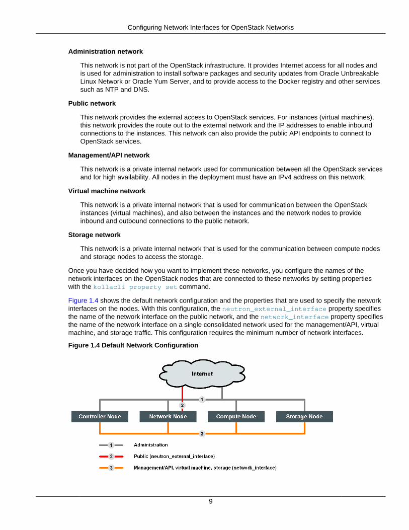
Figure 1.4 shows the default network configuration and the properties that are used to specify the networkinterfaces on the nodes. With this configuration, the neutron_external_interface property specifiesthe name of the network interface on the public network, and the network_interface property specifiesthe name of the network interface on a single consolidated network used for the management/API, virtualmachine, and storage traffic. This configuration requires the minimum number of network interfaces.
Figure 1.4 Default Network Configuration
Configuring OpenStack Service Endpoints
10
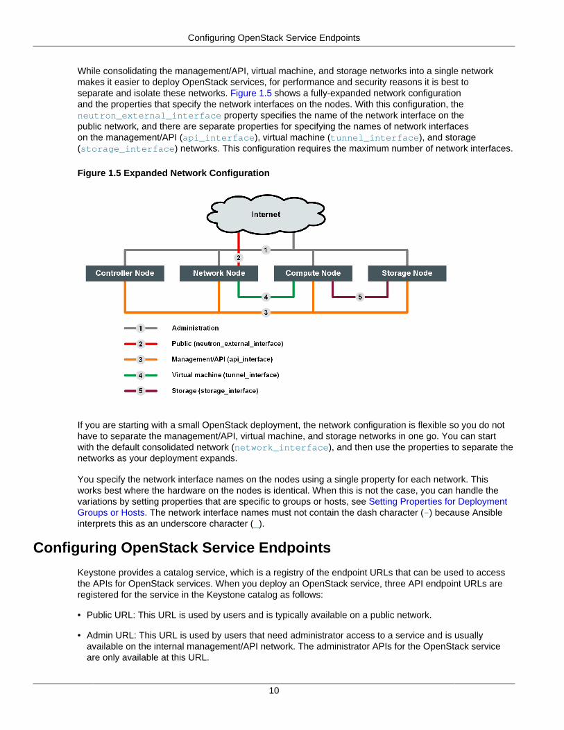
While consolidating the management/API, virtual machine, and storage networks into a single networkmakes it easier to deploy OpenStack services, for performance and security reasons it is best toseparate and isolate these networks. Figure 1.5 shows a fully-expanded network configurationand the properties that specify the network interfaces on the nodes. With this configuration, theneutron_external_interface property specifies the name of the network interface on thepublic network, and there are separate properties for specifying the names of network interfaceson the management/API (api_interface), virtual machine (tunnel_interface), and storage(storage_interface) networks. This configuration requires the maximum number of network interfaces.
Figure 1.5 Expanded Network Configuration
If you are starting with a small OpenStack deployment, the network configuration is flexible so you do nothave to separate the management/API, virtual machine, and storage networks in one go. You can startwith the default consolidated network (network_interface), and then use the properties to separate thenetworks as your deployment expands.
You specify the network interface names on the nodes using a single property for each network. Thisworks best where the hardware on the nodes is identical. When this is not the case, you can handle thevariations by setting properties that are specific to groups or hosts, see Setting Properties for DeploymentGroups or Hosts. The network interface names must not contain the dash character (-) because Ansibleinterprets this as an underscore character (_).
Configuring OpenStack Service Endpoints
Keystone provides a catalog service, which is a registry of the endpoint URLs that can be used to accessthe APIs for OpenStack services. When you deploy an OpenStack service, three API endpoint URLs areregistered for the service in the Keystone catalog as follows:
• Public URL: This URL is used by users and is typically available on a public network.
• Admin URL: This URL is used by users that need administrator access to a service and is usuallyavailable on the internal management/API network. The administrator APIs for the OpenStack serviceare only available at this URL.
Configuring OpenStack Service Endpoints
11
• Internal URL: This URL is used for communication between OpenStack services and is usually availableon the internal management/API network.
Before you deploy OpenStack services, you use the kollacli property set command to set theproperties that configure the endpoint URLs. The following are the main properties to set.
network_interface
The name of the network interface (for example, em1) on all nodes which is connected to the internalmanagement/API network.
kolla_internal_vip_address
An unused IP address on the internal management/API network.
In an OpenStack deployment, Keepalived manages this address as a virtual IP (VIP) address andassigns it to the network_interface on one of the controller nodes.
kolla_external_vip_interface
The name of the network interface (for example, em3) on all controller nodes which is connected tothe public network.
By default, this property is mapped to network_interface.
Caution: The interface must not be the same as the interface specified for theneutron_external_interface.
kolla_external_vip_address
An unused IP address on a public network.
In an OpenStack deployment, Keepalived manages this address as a VIP address and assignsit to the kolla_external_vip_interface on the controller node that currently manages thekolla_internal_vip_address.
By default, this property is mapped to kolla_internal_vip_address.
The minimum properties you should set are network_interface and kolla_internal_vipaddress. With this configuration, the same IP address on the internal management/API network is usedfor all endpoint URLs.
To configure the public URL endpoint to be a different IP address on a public network, set thekolla_external_vip_interface and kolla_external_vip_address properties.
If the nodes have differing network interface names, use group and host properties to set different interfacenames, see Setting Properties for Deployment Groups or Hosts.
You can also use fully qualified DNS names for the endpoints instead of IP addresses by setting thekolla_internal_fqdn and kolla_external_fqdn properties. By default, these properties aremapped to the internal and external VIP address. If you set these properties, you must configure your DNSto ensure that the names resolve correctly to the internal and external VIP address.
Another important component of an API endpoint URL is the network port to use. The ports are fullyconfigurable by setting the appropriate <service>_admin_port and <service>_public_portproperties for each service. These properties are preconfigured with the default ports for each service, forexample, 35357 for the keystone_admin_port and 5000 for the keystone_public_port. You onlyneed to set these properties if you want to change the default ports.
Configuring OpenStack Service Accounts
12
If you want to manually configure an endpoint for a service, you can also do this bysetting the <service>_public_endpoint, <service>_admin_endpoint, or<service>_internal_endpoint properties. Normally you do not need to do this.
Oracle OpenStack uses Keepalived and HAProxy to provide high availability and load balancing for theOpenStack service endpoints, see Service Endpoint High Availability (Keepalived and HAProxy).
Configuring OpenStack Service Accounts
When you deploy an OpenStack service, the credentials for the service admin user are registered with theKeystone service.
The user name for the service user is the name of the service, for example nova for the Novaservice. Normally you do not need to change the name, but the name is configurable (theservice_keystone_user property). The Admin project user name, admin by default, is alsoconfigurable (the keystone_admin_user property).
You must set passwords for the Admin project user and the Keystone service users before you deployOpenStack services. You manage passwords with the kollacli password family of commands. Youcan set the passwords for individual services with the kollacli password set command:
$ kollacli password set password_name
The service password names are:
• keystone_admin_password: The password for the Admin project user that performs administrativetasks in your OpenStack deployment.
• service_keystone_password: The Keystone password for a service.
Alternatively, you can use the kollacli password init command to set all the passwords at onceusing random secure passwords.
If you set passwords individually using the kollacli password set command, it is best to run thekollacli password init command afterward, as this command sets values for the password namesthat do not have a value.
Caution
If you want to clear a password, for example because you want generate a securerandom password using kollacli password init, use the kollaclipassword set command to set an empty password. Do not use the kollaclipassword clear command as this removes both the password and the passwordname.
Once you deploy Oracle OpenStack, you must ensure that any password changes applied to Keystoneservice users are also applied to your configuration (using the kollacli password set command) sothat the password changes are preserved when you upgrade or redeploy.
Password Security
The passwords you set are stored in the /etc/kolla/passwords.yml file on the master node. Thekollacli password command is the only supported method for managing the passwords in this file.
By default, the passwords.yml file is read-writable only by the kolla user and members of the kollagroup. For security reasons, you should restrict access to this user and group.
About the OpenStack Kolla User
13
When setting passwords individually, it is best to use a random strong password generator to generatesecure passwords. The kollacli password init generates strong random passwords for you.
About the OpenStack Kolla User
Oracle OpenStack uses Ansible to deploy the OpenStack Docker containers to the nodes. Ansible requiresan SSH login on the nodes, and Oracle OpenStack uses the kolla user and SSH keys for this purpose.The configuration of the kolla user happens automatically, as follows.
When you prepare nodes by installing either the openstack-kolla-preinstall package or theopenstack-kollacli package, the openstack-kolla-user package is also installed. This packageprepares the kolla user and performs the following operations on the node:
• Create the kolla group.
The kolla group is for the users that run the kollacli command.
• Create the docker group.
The docker group enables non-root users to run docker commands.
• Create the kolla user.
The user is created as a system user with the home directory set to /usr/share/kolla. The user isadded to the kolla and docker groups, with the kolla group as the primary group. No private groupis created for the user.
• Set up sudoers for the kolla user.
Configuration is added either to the /etc/sudoers.d/kolla or the /etc/sudoers configuration file.
The configuration enables the kolla user to run commands, such as ansible and ansible-playbook, as root without prompting for a password.
• Set up SSH for the kolla user.
The SSH configuration directory (.ssh) is created in the kolla user's home directory, theauthorized_keys file is created in the .ssh directory.
When you install the openstack-kollacli package on the master node, SSH public and private keysare created for the kolla user on the master node.
When you run the kollacli host setup command, as described in Setting up a Deployment, thepublic key is copied from the master node to the kolla user's authorized_keys file on the nodes.

14
15
Chapter 2 Openstack Service Configuration
Table of ContentsBarbican Key Manager Service ......................................................................................................... 16Cinder Block Storage Service ........................................................................................................... 17
Using LVM for Cinder Volumes ................................................................................................. 18Using External iSCSI Storage for Cinder Volumes ..................................................................... 19Configuring the iSCSI Initiator Name and iSCSI Multipath .......................................................... 21Using the NFS Backup Driver for Cinder Backup ....................................................................... 22Using the Swift Backup Driver for Cinder Backup ...................................................................... 22Using Shared Cinder Volumes (Multi-Attached) .......................................................................... 22
Glance Image Service ...................................................................................................................... 23Murano Application Catalog Service .................................................................................................. 24Neutron Networking Service .............................................................................................................. 24
Setting up Multiple External Network Interfaces ......................................................................... 24Enabling Distributed Virtual Routing (DVR) ................................................................................ 25Enabling Neutron Agent High Availability ................................................................................... 26Neutron Plugins: Firewalls and Load Balancing ......................................................................... 26
Nova Compute Service ..................................................................................................................... 26Hypervisors Supported .............................................................................................................. 26Automatic Hypervisor Configuration ........................................................................................... 28Introduction to Oracle VM Server .............................................................................................. 28Preparing a Compute Node ...................................................................................................... 29Removing a Compute Node ...................................................................................................... 30
Swift Object Storage Service ............................................................................................................ 31Preparing the Storage Devices ................................................................................................. 31Building the Swift Rings ............................................................................................................ 32Enabling and Configuring Swift ................................................................................................. 35
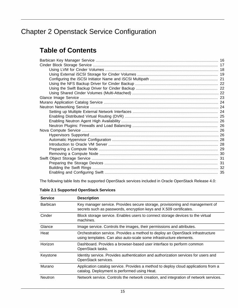
The following table lists the supported OpenStack services included in Oracle OpenStack Release 4.0:
Table 2.1 Supported OpenStack Services
Service Description
Barbican Key manager service. Provides secure storage, provisioning and management ofsecrets such as passwords, encryption keys and X.509 certificates.
Cinder Block storage service. Enables users to connect storage devices to the virtualmachines.
Glance Image service. Controls the images, their permissions and attributes.
Heat Orchestration service. Provides a method to deploy an OpenStack infrastructureusing templates. Can also auto-scale some infrastructure elements.
Horizon Dashboard. Provides a browser-based user interface to perform commonOpenStack tasks.
Keystone Identity service. Provides authentication and authorization services for users andOpenStack services.
Murano Application catalog service. Provides a method to deploy cloud applications from acatalog. Deployment is performed using Heat.
Neutron Network service. Controls the network creation, and integration of network services.
Barbican Key Manager Service
16
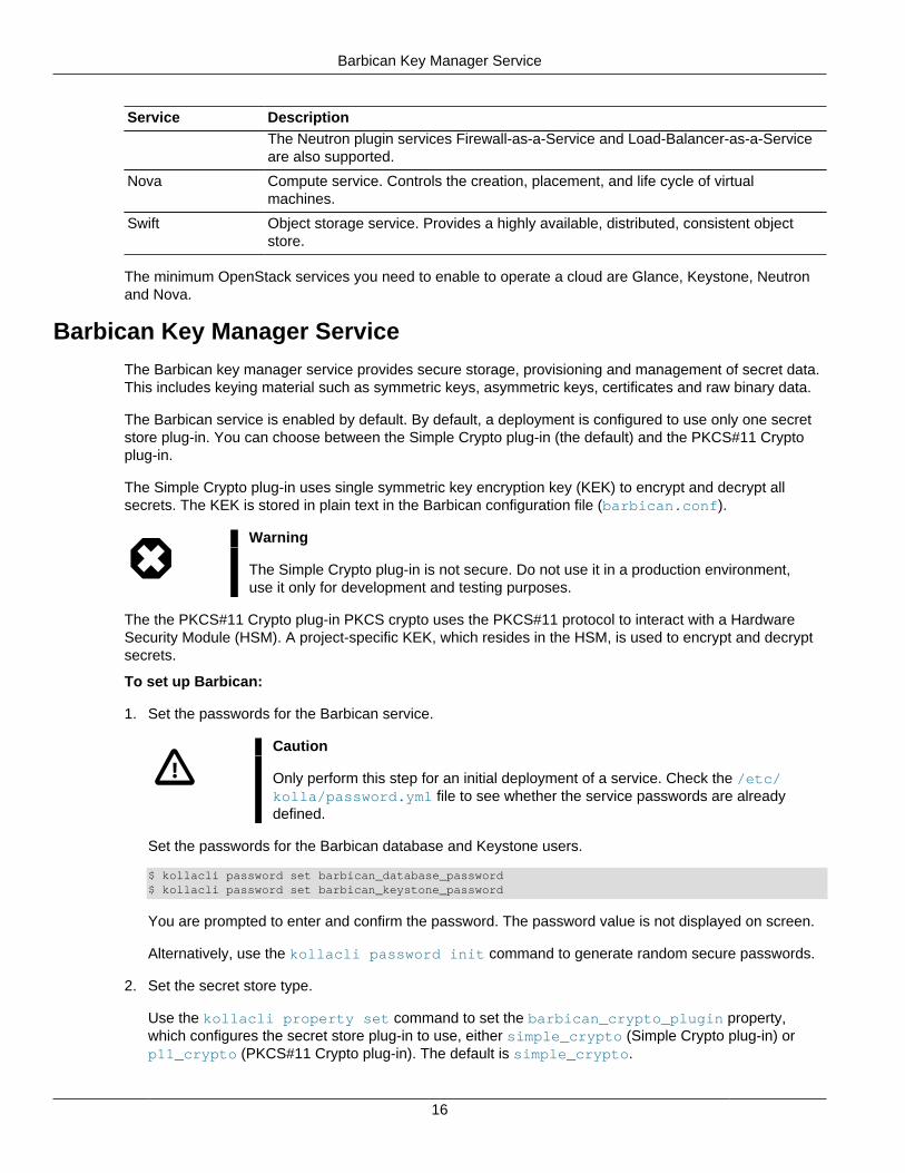
Service DescriptionThe Neutron plugin services Firewall-as-a-Service and Load-Balancer-as-a-Serviceare also supported.
Nova Compute service. Controls the creation, placement, and life cycle of virtualmachines.
Swift Object storage service. Provides a highly available, distributed, consistent objectstore.
The minimum OpenStack services you need to enable to operate a cloud are Glance, Keystone, Neutronand Nova.
Barbican Key Manager Service
The Barbican key manager service provides secure storage, provisioning and management of secret data.This includes keying material such as symmetric keys, asymmetric keys, certificates and raw binary data.
The Barbican service is enabled by default. By default, a deployment is configured to use only one secretstore plug-in. You can choose between the Simple Crypto plug-in (the default) and the PKCS#11 Cryptoplug-in.
The Simple Crypto plug-in uses single symmetric key encryption key (KEK) to encrypt and decrypt allsecrets. The KEK is stored in plain text in the Barbican configuration file (barbican.conf).
Warning
The Simple Crypto plug-in is not secure. Do not use it in a production environment,use it only for development and testing purposes.
The the PKCS#11 Crypto plug-in PKCS crypto uses the PKCS#11 protocol to interact with a HardwareSecurity Module (HSM). A project-specific KEK, which resides in the HSM, is used to encrypt and decryptsecrets.
To set up Barbican:
1. Set the passwords for the Barbican service.
Caution
Only perform this step for an initial deployment of a service. Check the /etc/kolla/password.yml file to see whether the service passwords are alreadydefined.
Set the passwords for the Barbican database and Keystone users.
$ kollacli password set barbican_database_password$ kollacli password set barbican_keystone_password
You are prompted to enter and confirm the password. The password value is not displayed on screen.
Alternatively, use the kollacli password init command to generate random secure passwords.
2. Set the secret store type.
Use the kollacli property set command to set the barbican_crypto_plugin property,which configures the secret store plug-in to use, either simple_crypto (Simple Crypto plug-in) orp11_crypto (PKCS#11 Crypto plug-in). The default is simple_crypto.
Cinder Block Storage Service
17
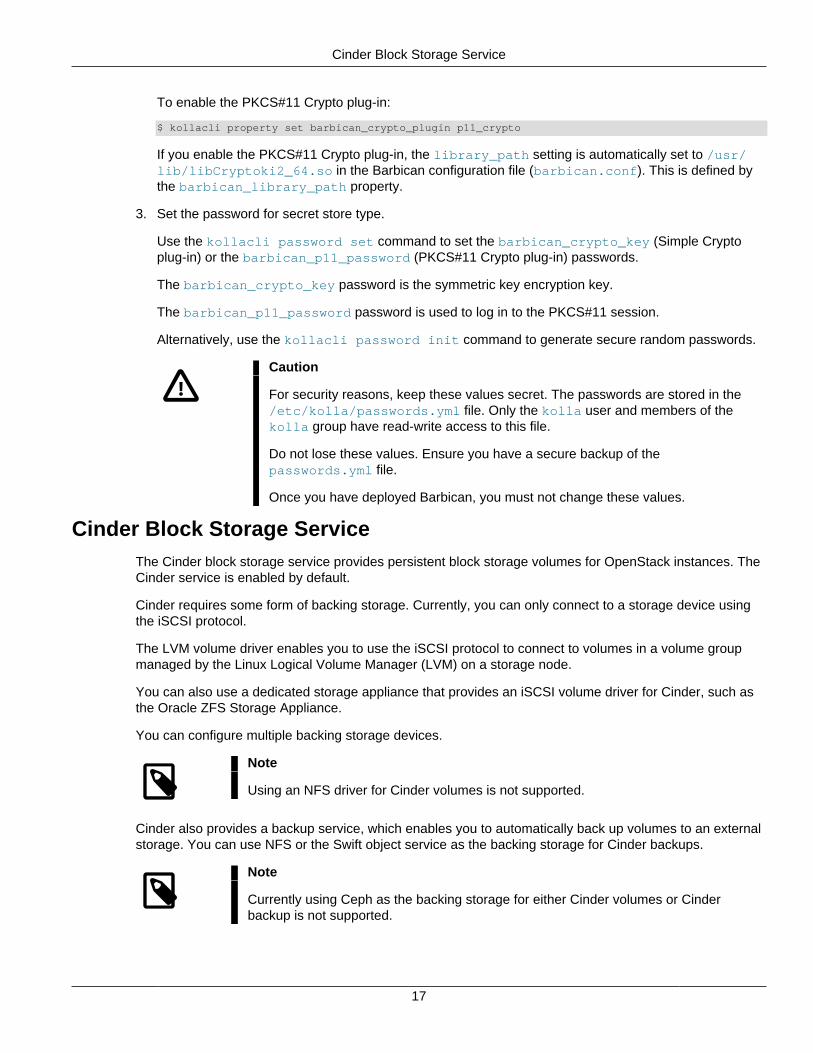
To enable the PKCS#11 Crypto plug-in:
$ kollacli property set barbican_crypto_plugin p11_crypto
If you enable the PKCS#11 Crypto plug-in, the library_path setting is automatically set to /usr/lib/libCryptoki2_64.so in the Barbican configuration file (barbican.conf). This is defined bythe barbican_library_path property.
3. Set the password for secret store type.
Use the kollacli password set command to set the barbican_crypto_key (Simple Cryptoplug-in) or the barbican_p11_password (PKCS#11 Crypto plug-in) passwords.
The barbican_crypto_key password is the symmetric key encryption key.
The barbican_p11_password password is used to log in to the PKCS#11 session.
Alternatively, use the kollacli password init command to generate secure random passwords.
Caution
For security reasons, keep these values secret. The passwords are stored in the/etc/kolla/passwords.yml file. Only the kolla user and members of thekolla group have read-write access to this file.
Do not lose these values. Ensure you have a secure backup of thepasswords.yml file.
Once you have deployed Barbican, you must not change these values.
Cinder Block Storage ServiceThe Cinder block storage service provides persistent block storage volumes for OpenStack instances. TheCinder service is enabled by default.
Cinder requires some form of backing storage. Currently, you can only connect to a storage device usingthe iSCSI protocol.
The LVM volume driver enables you to use the iSCSI protocol to connect to volumes in a volume groupmanaged by the Linux Logical Volume Manager (LVM) on a storage node.
You can also use a dedicated storage appliance that provides an iSCSI volume driver for Cinder, such asthe Oracle ZFS Storage Appliance.
You can configure multiple backing storage devices.
Note
Using an NFS driver for Cinder volumes is not supported.
Cinder also provides a backup service, which enables you to automatically back up volumes to an externalstorage. You can use NFS or the Swift object service as the backing storage for Cinder backups.
Note
Currently using Ceph as the backing storage for either Cinder volumes or Cinderbackup is not supported.
Using LVM for Cinder Volumes
18
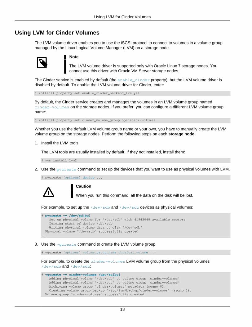
Using LVM for Cinder Volumes
The LVM volume driver enables you to use the iSCSI protocol to connect to volumes in a volume groupmanaged by the Linux Logical Volume Manager (LVM) on a storage node.
Note
The LVM volume driver is supported only with Oracle Linux 7 storage nodes. Youcannot use this driver with Oracle VM Server storage nodes.
The Cinder service is enabled by default (the enable_cinder property), but the LVM volume driver isdisabled by default. To enable the LVM volume driver for Cinder, enter:
$ kollacli property set enable_cinder_backend_lvm yes
By default, the Cinder service creates and manages the volumes in an LVM volume group namedcinder-volumes on the storage nodes. If you prefer, you can configure a different LVM volume groupname:
$ kollacli property set cinder_volume_group openstack-volumes
Whether you use the default LVM volume group name or your own, you have to manually create the LVMvolume group on the storage nodes. Perform the following steps on each storage node:
1. Install the LVM tools.
The LVM tools are usually installed by default. If they not installed, install them:
# yum install lvm2
2. Use the pvcreate command to set up the devices that you want to use as physical volumes with LVM.
# pvcreate [options] device ...
Caution
When you run this command, all the data on the disk will be lost.
For example, to set up the /dev/sdb and /dev/sdc devices as physical volumes:
# pvcreate -v /dev/sd[bc] Set up physical volume for "/dev/sdb" with 41943040 available sectors Zeroing start of device /dev/sdb Writing physical volume data to disk "/dev/sdb" Physical volume "/dev/sdb" successfully created...
3. Use the vgcreate command to create the LVM volume group.
# vgcreate [options] volume_group_name physical_volume ...
For example, to create the cinder-volumes LVM volume group from the physical volumes/dev/sdb and /dev/sdc:
# vgcreate -v cinder-volumes /dev/sd[bc] Adding physical volume '/dev/sdb' to volume group 'cinder-volumes' Adding physical volume '/dev/sdc' to volume group 'cinder-volumes' Archiving volume group "cinder-volumes" metadata (seqno 0). Creating volume group backup "/etc/lvm/backup/cinder-volumes" (seqno 1). Volume group "cinder-volumes" successfully created

Using External iSCSI Storage for Cinder Volumes
19
For more information, see the lvm(8), pvcreate(8), vgcreate(8), and other LVM manual pages.
Using External iSCSI Storage for Cinder Volumes
If you have a dedicated Oracle ZFS Storage Appliance (ZFSSA) storage appliance, you can use it forCinder storage. You can use ZFSSA storage in addition to LVM storage. The Cinder service and the iSCSIstorage backend are enabled by default (with the enable_cinder property).
Many of the properties listed in this section relate to ZFSAA features. For information on those features,see the Oracle® ZFS Storage Appliance Administration Guide, Release OS8.7.x at:
https://docs.oracle.com/cd/E79446_01/html/E79457/
Note
Connecting to the ZFSSA storage is not supported with CEPH.
To enable and configure the ZFSSA driver, use the kollacli property set command to set thefollowing properties:
enable_cinder_backend_zfssa_iscsi
Whether to enable the ZFSSA driver. Set this property to yes to enable the ZFSSA driver for Cinder.The default is no.
zfssa_iscsi_multiattach_enabled
Whether to enable multi-attached volumes on the ZFSSA. Set this property to yes to enable multi-attach enabled volumes. Multi-attach volumes are required for the Oracle Real Application Clusters12c application. Using multi-attached enabled disks for any other purpose is not supported.
zfssa_iscsi_san_ip
The IP address of the ZFSSA host.
zfssa_iscsi_login
The user name to log into the ZFSSA host. The password for this user is set below.
zfssa_iscsi_pool
The ZFSSA storage pool name.
zfssa_iscsi_project
The ZFSSA project name.
zfssa_iscsi_initiator
A comma separated list of IQNs (iSCSI Qualified Names).
zfssa_iscsi_initiator_config
The ZFSSA storage initiator configuration.
zfssa_iscsi_initiator_group
The ZFSSA storage initiator group name.
Using External iSCSI Storage for Cinder Volumes
20
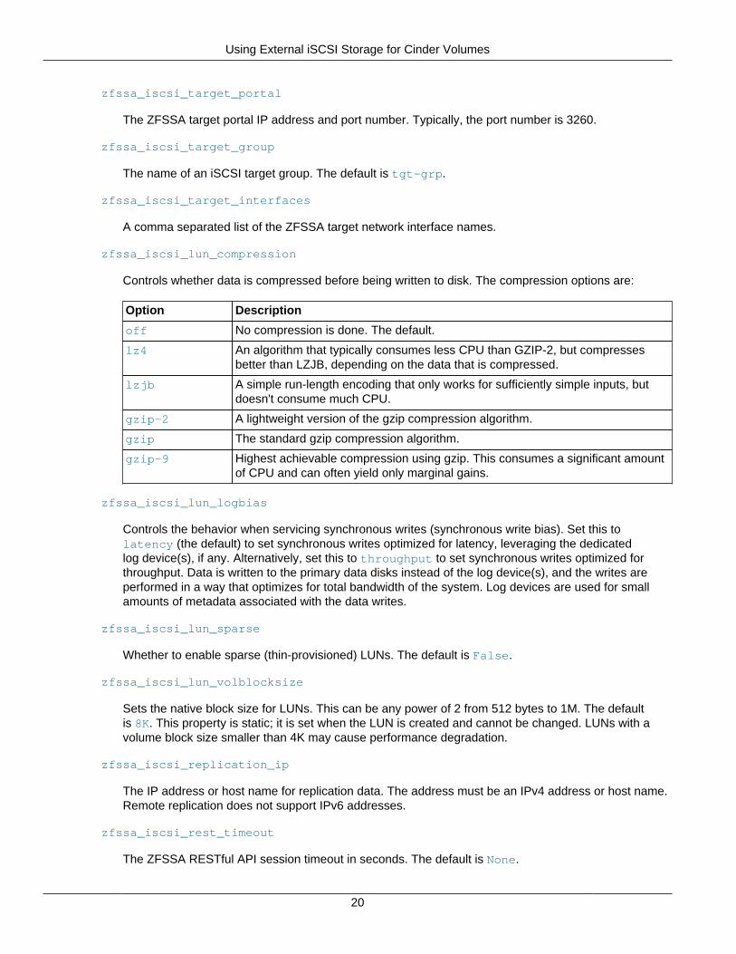
zfssa_iscsi_target_portal
The ZFSSA target portal IP address and port number. Typically, the port number is 3260.
zfssa_iscsi_target_group
The name of an iSCSI target group. The default is tgt-grp.
zfssa_iscsi_target_interfaces
A comma separated list of the ZFSSA target network interface names.
zfssa_iscsi_lun_compression
Controls whether data is compressed before being written to disk. The compression options are:
Option Description
off No compression is done. The default.
lz4 An algorithm that typically consumes less CPU than GZIP-2, but compressesbetter than LZJB, depending on the data that is compressed.
lzjb A simple run-length encoding that only works for sufficiently simple inputs, butdoesn't consume much CPU.
gzip-2 A lightweight version of the gzip compression algorithm.
gzip The standard gzip compression algorithm.
gzip-9 Highest achievable compression using gzip. This consumes a significant amountof CPU and can often yield only marginal gains.
zfssa_iscsi_lun_logbias
Controls the behavior when servicing synchronous writes (synchronous write bias). Set this tolatency (the default) to set synchronous writes optimized for latency, leveraging the dedicatedlog device(s), if any. Alternatively, set this to throughput to set synchronous writes optimized forthroughput. Data is written to the primary data disks instead of the log device(s), and the writes areperformed in a way that optimizes for total bandwidth of the system. Log devices are used for smallamounts of metadata associated with the data writes.
zfssa_iscsi_lun_sparse
Whether to enable sparse (thin-provisioned) LUNs. The default is False.
zfssa_iscsi_lun_volblocksize
Sets the native block size for LUNs. This can be any power of 2 from 512 bytes to 1M. The defaultis 8K. This property is static; it is set when the LUN is created and cannot be changed. LUNs with avolume block size smaller than 4K may cause performance degradation.
zfssa_iscsi_replication_ip
The IP address or host name for replication data. The address must be an IPv4 address or host name.Remote replication does not support IPv6 addresses.
zfssa_iscsi_rest_timeout
The ZFSSA RESTful API session timeout in seconds. The default is None.
Configuring the iSCSI Initiator Name and iSCSI Multipath
21
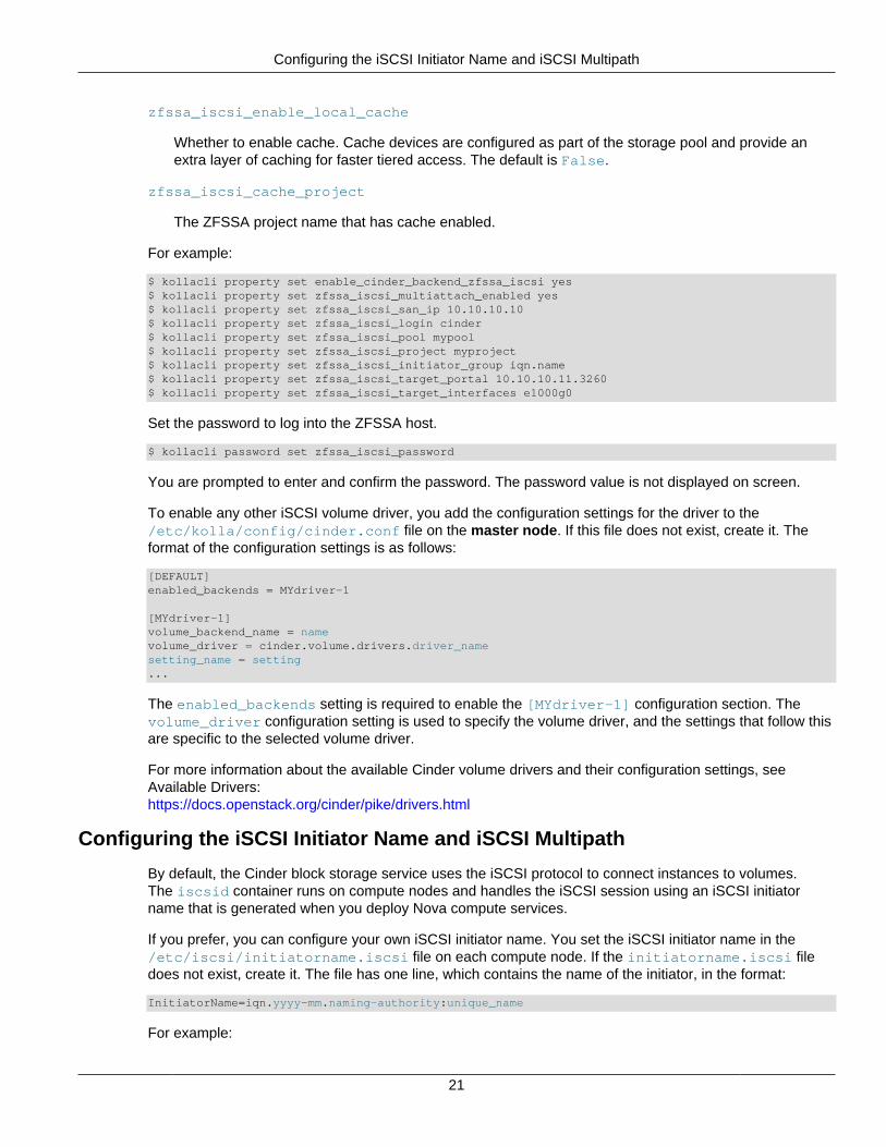
zfssa_iscsi_enable_local_cache
Whether to enable cache. Cache devices are configured as part of the storage pool and provide anextra layer of caching for faster tiered access. The default is False.
zfssa_iscsi_cache_project
The ZFSSA project name that has cache enabled.
For example:
$ kollacli property set enable_cinder_backend_zfssa_iscsi yes$ kollacli property set zfssa_iscsi_multiattach_enabled yes$ kollacli property set zfssa_iscsi_san_ip 10.10.10.10$ kollacli property set zfssa_iscsi_login cinder$ kollacli property set zfssa_iscsi_pool mypool$ kollacli property set zfssa_iscsi_project myproject$ kollacli property set zfssa_iscsi_initiator_group iqn.name$ kollacli property set zfssa_iscsi_target_portal 10.10.10.11.3260$ kollacli property set zfssa_iscsi_target_interfaces e1000g0
Set the password to log into the ZFSSA host.
$ kollacli password set zfssa_iscsi_password
You are prompted to enter and confirm the password. The password value is not displayed on screen.
To enable any other iSCSI volume driver, you add the configuration settings for the driver to the/etc/kolla/config/cinder.conf file on the master node. If this file does not exist, create it. Theformat of the configuration settings is as follows:
[DEFAULT]enabled_backends = MYdriver-1
[MYdriver-1]volume_backend_name = namevolume_driver = cinder.volume.drivers.driver_namesetting_name = setting...
The enabled_backends setting is required to enable the [MYdriver-1] configuration section. Thevolume_driver configuration setting is used to specify the volume driver, and the settings that follow thisare specific to the selected volume driver.
For more information about the available Cinder volume drivers and their configuration settings, seeAvailable Drivers:https://docs.openstack.org/cinder/pike/drivers.html
Configuring the iSCSI Initiator Name and iSCSI Multipath
By default, the Cinder block storage service uses the iSCSI protocol to connect instances to volumes.The iscsid container runs on compute nodes and handles the iSCSI session using an iSCSI initiatorname that is generated when you deploy Nova compute services.
If you prefer, you can configure your own iSCSI initiator name. You set the iSCSI initiator name in the/etc/iscsi/initiatorname.iscsi file on each compute node. If the initiatorname.iscsi filedoes not exist, create it. The file has one line, which contains the name of the initiator, in the format:
InitiatorName=iqn.yyyy-mm.naming-authority:unique_name
For example:
Using the NFS Backup Driver for Cinder Backup
22
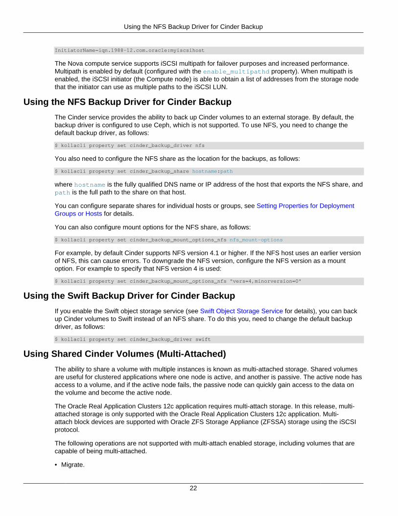
InitiatorName=iqn.1988-12.com.oracle:myiscsihost
The Nova compute service supports iSCSI multipath for failover purposes and increased performance.Multipath is enabled by default (configured with the enable_multipathd property). When multipath isenabled, the iSCSI initiator (the Compute node) is able to obtain a list of addresses from the storage nodethat the initiator can use as multiple paths to the iSCSI LUN.
Using the NFS Backup Driver for Cinder Backup
The Cinder service provides the ability to back up Cinder volumes to an external storage. By default, thebackup driver is configured to use Ceph, which is not supported. To use NFS, you need to change thedefault backup driver, as follows:
$ kollacli property set cinder_backup_driver nfs
You also need to configure the NFS share as the location for the backups, as follows:
$ kollacli property set cinder_backup_share hostname:path
where hostname is the fully qualified DNS name or IP address of the host that exports the NFS share, andpath is the full path to the share on that host.
You can configure separate shares for individual hosts or groups, see Setting Properties for DeploymentGroups or Hosts for details.
You can also configure mount options for the NFS share, as follows:
$ kollacli property set cinder_backup_mount_options_nfs nfs_mount-options
For example, by default Cinder supports NFS version 4.1 or higher. If the NFS host uses an earlier versionof NFS, this can cause errors. To downgrade the NFS version, configure the NFS version as a mountoption. For example to specify that NFS version 4 is used:
$ kollacli property set cinder_backup_mount_options_nfs "vers=4,minorversion=0"
Using the Swift Backup Driver for Cinder Backup
If you enable the Swift object storage service (see Swift Object Storage Service for details), you can backup Cinder volumes to Swift instead of an NFS share. To do this you, need to change the default backupdriver, as follows:
$ kollacli property set cinder_backup_driver swift
Using Shared Cinder Volumes (Multi-Attached)
The ability to share a volume with multiple instances is known as multi-attached storage. Shared volumesare useful for clustered applications where one node is active, and another is passive. The active node hasaccess to a volume, and if the active node fails, the passive node can quickly gain access to the data onthe volume and become the active node.
The Oracle Real Application Clusters 12c application requires multi-attach storage. In this release, multi-attached storage is only supported with the Oracle Real Application Clusters 12c application. Multi-attach block devices are supported with Oracle ZFS Storage Appliance (ZFSSA) storage using the iSCSIprotocol.
The following operations are not supported with multi-attach enabled storage, including volumes that arecapable of being multi-attached.
• Migrate.
Glance Image Service
23
• Live-migrate.
• Volume swap/volume update (unless the new volume is also multi-attach enabled).
• Shelve and shelve-offload.
• Rebuild.
The Oracle Real Application Clusters 12c application automatically creates multi-attach enabled volumesduring the deployment of the application. You do not need to manually set a volume to be multi-attachenabled.
To enable multi-attach for the ZFSSA array, see Using External iSCSI Storage for Cinder Volumes.
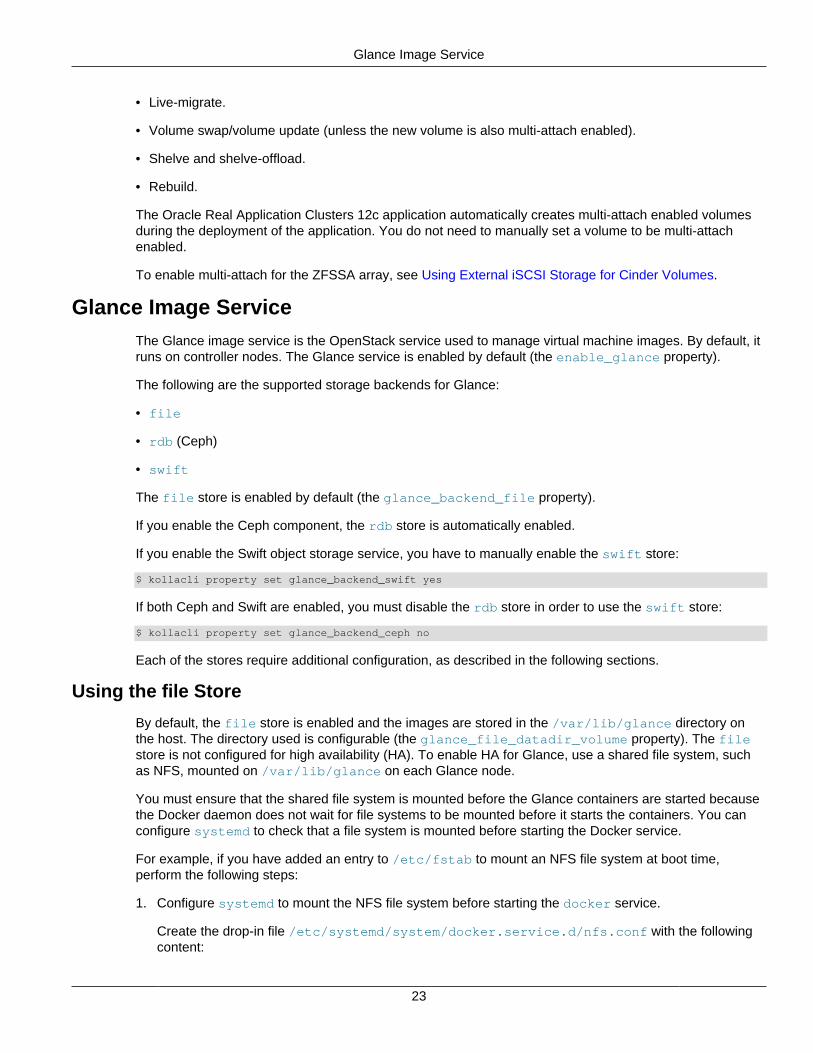
Glance Image ServiceThe Glance image service is the OpenStack service used to manage virtual machine images. By default, itruns on controller nodes. The Glance service is enabled by default (the enable_glance property).
The following are the supported storage backends for Glance:
• file
• rdb (Ceph)
• swift
The file store is enabled by default (the glance_backend_file property).
If you enable the Ceph component, the rdb store is automatically enabled.
If you enable the Swift object storage service, you have to manually enable the swift store:
$ kollacli property set glance_backend_swift yes
If both Ceph and Swift are enabled, you must disable the rdb store in order to use the swift store:
$ kollacli property set glance_backend_ceph no
Each of the stores require additional configuration, as described in the following sections.
Using the file Store
By default, the file store is enabled and the images are stored in the /var/lib/glance directory onthe host. The directory used is configurable (the glance_file_datadir_volume property). The filestore is not configured for high availability (HA). To enable HA for Glance, use a shared file system, suchas NFS, mounted on /var/lib/glance on each Glance node.
You must ensure that the shared file system is mounted before the Glance containers are started becausethe Docker daemon does not wait for file systems to be mounted before it starts the containers. You canconfigure systemd to check that a file system is mounted before starting the Docker service.
For example, if you have added an entry to /etc/fstab to mount an NFS file system at boot time,perform the following steps:
1. Configure systemd to mount the NFS file system before starting the docker service.
Create the drop-in file /etc/systemd/system/docker.service.d/nfs.conf with the followingcontent:
Using the rdb Store
24
[Unit]After=remote-fs.target
2. Reload systemd manager configuration.
# systemctl daemon-reload
3. Restart the docker service.
# systemctl restart docker.service
Using the rdb Store
To use the rdb store for Glance, you must enable the Ceph component, and prepare the storage devices,as described in Setting up Ceph Storage.
By default, the images are stored in a Ceph pool named images. The pool name is configurable (theglance_pool_name property).
The Ceph pool is a replicated pool by default, which means every image is copied to multiple disks. Tosave disk space, the pool can be configured as an erasure-coded pool instead:
$ kollacli property set glance_pool_type erasure
If you use Ceph cache tiering, you can configure the cache tier mode to use (the ceph_cache_modeproperty), either forward, none, or writeback (the default).
Using the swift Store
To use the swift store for Glance, you must enable the Swift service, prepare the storage devices, andcreate the initial rings, as described in Swift Object Storage Service.
The images are stored in a Swift container named glance.
Murano Application Catalog Service
The Murano application catalog service provides a method for creating and deploying cloud-readyapplications.
For information on how to set up applications and deploy them using Murano, see the Oracle OpenStackApplication Deployment Guide at: https://docs.oracle.com/cd/E90981_01/E90977/html/index.html
Neutron Networking Service
The Neutron network service enables you to create and attach interface devices managed by otherOpenStack services to networks.
Setting up Multiple External Network Interfaces
The default network interface to connect to the external (public) network is a single network interface.You can change the configuration to enable more than one network interface to connect to the externalnetwork.
To set up multiple external network interfaces, use the kollacli property set command to configurethe following properties before you perform the deployment:
Enabling Distributed Virtual Routing (DVR)
25
neutron_external_interface
The name of the network interfaces. The default is eth1. To use multiple external network interfaces,use a comma-separated list.
neutron_bridge_name
The name of the network bridges. The default is br-ex. To use multiple bridges, use a comma-separated list.
For example, to set up multiple external network interfaces by specifying the NICs and bridges to theexternal networks:
$ kollacli property set neutron_external_interface em2,em3$ kollacli property set neutron_bridge_name br-ex1,br-ex2
Enabling Distributed Virtual Routing (DVR)
In a default Oracle OpenStack deployment, the routers that provide the connectivity between tenant(project) networks, and between tenant networks and external networks, are created as a single virtualrouter on a network node. This represents a potential point of failure, and has implications for performanceand scalability.
To address this issue, you can enable Distributed Virtual Routing (DVR). With DVR, routers are createdautomatically on compute nodes as instances are connected to networks. The routers on the computenodes can route connections between instances on the same tenant network, and connections betweeninstances and external networks, where instances have been assigned a floating IP. Connections betweeninstances without a floating IP and external networks are handled by the network node.
If you enable DVR, you must disable the Neutron plug-ins Firewall-as-a-Service (FWaaS) and Load-Balancer-as-a-Service (LBaaS). They are disabled by default.
DVR is not enabled by default. DVR only works with the Open vSwitch mechanism driver. Compute nodesmust have a network interface on the external network and the interface should not have an IP address.DVR can be used with all the supported tenant network types.
If you enable DVR, it is recommended that you also enable high availability for the virtual routers, seeEnabling Neutron Agent High Availability.
To enable DVR, use the kollacli property set command to configure the following properties beforeyou perform the deployment:
enable_neutron_dvr
Enable DVR. Valid settings are yes and no. The default is no.
neutron_external_interface
The name of the network interface (for example, em2) which is connected to the external networkwhere the neutron public network will be created. This interface should not have an IP addressand should not be the same as the interface specified for the network_interface property. Thisinterface must be available on all the network nodes, and on all the compute nodes. To use multipleexternal network interfaces, use a comma-separated list, for example:
$ kollacli property set neutron_external_interface em2,em3
neutron_plugin_agent
The name of the Neutron mechanism driver and agent. Valid settings are openvswitch andlinuxbridge. The default is openvswitch. For DVR, this must be set to openvswitch.
Enabling Neutron Agent High Availability
26
For example:
$ kollacli property set enable_neutron_dvr yes$ kollacli property set neutron_external_interface em2
Enabling Neutron Agent High Availability
Neutron agent high availability enables you to distribute virtual routers and DHCP agents across multiplenodes so that there is a backup for the services these components provide in the event of a failure.
For virtual routers, Neutron uses the Virtual Router Redundancy Protocol (VRRP) to provide highavailability of a network's default gateway by enabling two or more routers to provide backup for thisaddress. Only one virtual router is active (the master), the others are backups. The backups listen forregular VRRP multicast advertisement packets from the master. If the backups fail to receive a set numberof advertisement packets, a backup takes over as the master. You configure a minimum and a maximumnumber of virtual routers to ensure that high availability is maintained and that additional virtual routers areadded if you increase the number of network nodes.
For DHCP agents, you configure the number of agents you want to run for each project (tenant) network.
To enable Neutron agent high availability, use the kollacli property set command to configure thefollowing properties before you perform the deployment:
enable_neutron_agent_ha
Enable Neutron agent high availability. Valid settings are yes and no. The default is no.
dhcp_agents_per_network
The number of DHCP agents to run for each project (tenant) network. The default is 2. For highavailability, this must be set to 2 or more.
max_l3_agents_per_router
The maximum number of network nodes (or compute nodes if DVR is enabled) to use for each highlyavailable router. The default is 3.
Neutron Plugins: Firewalls and Load Balancing
Firewall-as-a-Service (FWaaS) and Load-Balancer-as-a-Service (LBaaS) are plug-ins for Neutron. If youenable these plug-ins, do not enable Neutron distributed virtual routing (DVR). Neutron DVR is disabled bydefault.
To enable the plug-ins:
$ kollacli property set enable_neutron_fwaas yes$ kollacli property set enable_neutron_lbaas yes
Nova Compute ServiceThe Nova compute service is responsible for managing the hypervisors and virtual machine instances. Youmight need to perform additional configuration before you deploy this service.
Hypervisors Supported
The following are the supported hypervisors for Oracle OpenStack:
• Kernel-based Virtual Machine (KVM) provided with Oracle Linux
Hypervisors Supported
27
• Xen hypervisor provided with Oracle VM Server
For details of the system requirements for these hypervisors, see System Requirements.
Support for Microsoft Hyper-V is available on request. Contact Oracle Support at https://support.oracle.com.
Supported Guest Operating Systems on Oracle Linux KVM
Oracle Linux Release 7 is the only guest operating system supported and certified on Oracle Linux KVMcompute nodes.
Oracle software products (such as the Oracle Database) are not certified on KVM-based compute nodes.To gain full certification for Oracle software products, you should use Oracle VM Server compute nodes torun Oracle software.
You may also be able to create instances with the guest operating systems supported by KVM, althoughno Oracle Support is offered for these operating systems. For a list of the operating systems supported byKVM, see:
http://www.linux-kvm.org/page/Guest_Support_Status
Supported Guest Operating Systems on Oracle VM Server
Oracle OpenStack supports the guest operating systems supported by Oracle VM, which includes OracleLinux, Oracle Solaris, Microsoft Windows, and other Linux distributions.
For a complete list of certified guest operating systems, see the Oracle VM Release Notes for Release 3.4at:
https://docs.oracle.com/cd/E64076_01/E64077/html/vmrns-guest-os-x86.html
For a list of certified Oracle software on Oracle VM Server, see the Oracle Support document CertifiedSoftware on Oracle VM, (Doc ID 464754.1) at:
https://support.oracle.com/epmos/faces/DocumentDisplay?id=464754.1
Supported OpenStack Features by Hypervisor
The following table summarises the OpenStack features supported by each hypervisor.
Feature Oracle Linux KVM Oracle VM Server
Nova cold migration Yes Yes
Nova live migration Yes Yes
Nova NUMA placement Yes No
Nova CPU pinning Yes No
Neutron DVR Yes No
For more detailed information about the features supported by each hypervisor, see the Nova FeatureClassification documentation at https://docs.openstack.org/nova/latest/user/feature-classification.html.
Live migration only works when an instance uses shared storage. For instances using ephemeral storage,you can enable shared storage by using Ceph storage, or by configuring the /var/lib/kolla/var/lib/nova/instances directory on compute nodes to use a shared file system such as NFS. Forinstances using persistent storage (Cinder volumes), you can enable shared storage by using the iSCSI
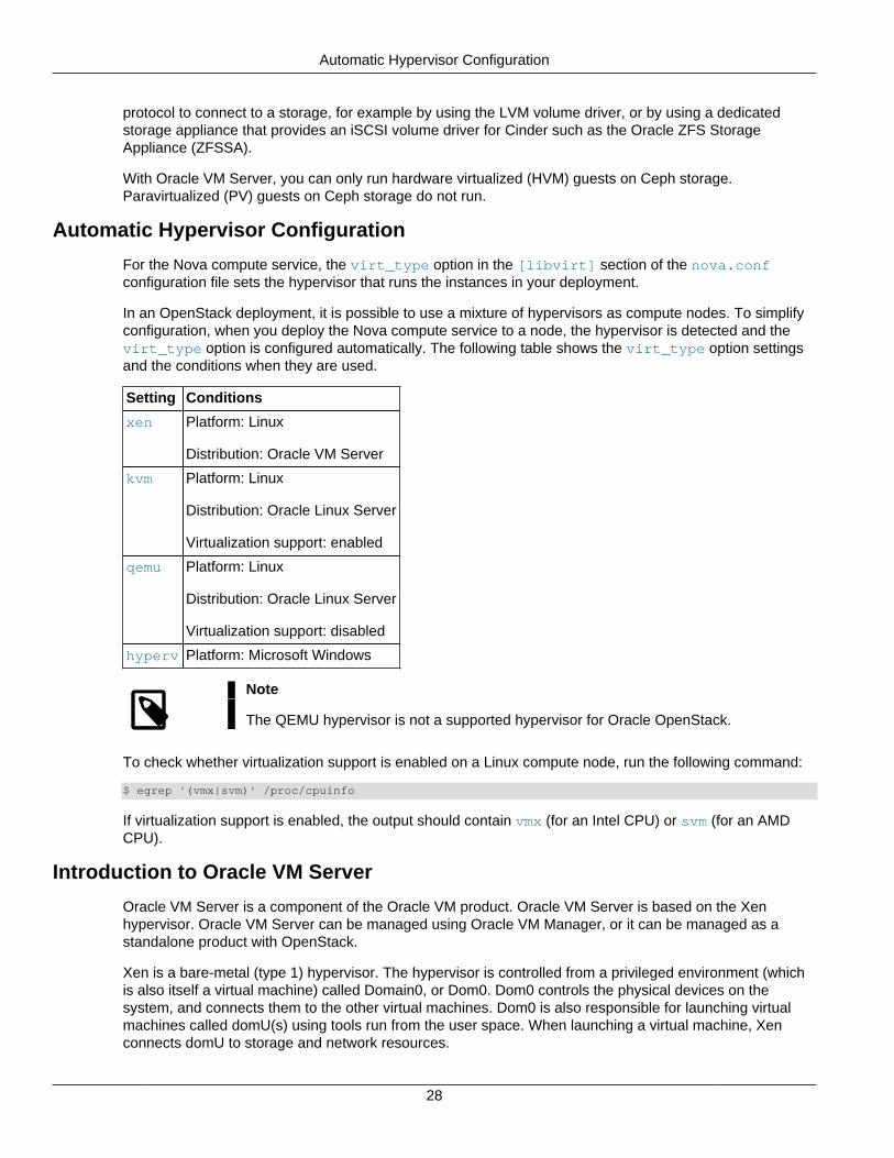
Automatic Hypervisor Configuration
28
protocol to connect to a storage, for example by using the LVM volume driver, or by using a dedicatedstorage appliance that provides an iSCSI volume driver for Cinder such as the Oracle ZFS StorageAppliance (ZFSSA).
With Oracle VM Server, you can only run hardware virtualized (HVM) guests on Ceph storage.Paravirtualized (PV) guests on Ceph storage do not run.
Automatic Hypervisor Configuration
For the Nova compute service, the virt_type option in the [libvirt] section of the nova.confconfiguration file sets the hypervisor that runs the instances in your deployment.
In an OpenStack deployment, it is possible to use a mixture of hypervisors as compute nodes. To simplifyconfiguration, when you deploy the Nova compute service to a node, the hypervisor is detected and thevirt_type option is configured automatically. The following table shows the virt_type option settingsand the conditions when they are used.
Setting Conditions
xen Platform: Linux
Distribution: Oracle VM Server
kvm Platform: Linux
Distribution: Oracle Linux Server
Virtualization support: enabled
qemu Platform: Linux
Distribution: Oracle Linux Server
Virtualization support: disabled
hyperv Platform: Microsoft Windows
Note
The QEMU hypervisor is not a supported hypervisor for Oracle OpenStack.
To check whether virtualization support is enabled on a Linux compute node, run the following command:
$ egrep '(vmx|svm)' /proc/cpuinfo
If virtualization support is enabled, the output should contain vmx (for an Intel CPU) or svm (for an AMDCPU).
Introduction to Oracle VM Server
Oracle VM Server is a component of the Oracle VM product. Oracle VM Server is based on the Xenhypervisor. Oracle VM Server can be managed using Oracle VM Manager, or it can be managed as astandalone product with OpenStack.
Xen is a bare-metal (type 1) hypervisor. The hypervisor is controlled from a privileged environment (whichis also itself a virtual machine) called Domain0, or Dom0. Dom0 controls the physical devices on thesystem, and connects them to the other virtual machines. Dom0 is also responsible for launching virtualmachines called domU(s) using tools run from the user space. When launching a virtual machine, Xenconnects domU to storage and network resources.
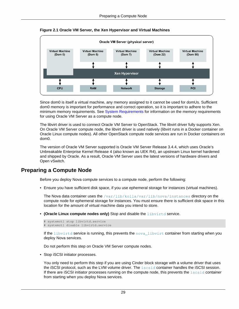
Preparing a Compute Node
29
Figure 2.1 Oracle VM Server, the Xen Hypervisor and Virtual Machines
Since dom0 is itself a virtual machine, any memory assigned to it cannot be used for domUs. Sufficientdom0 memory is important for performance and correct operation, so it is important to adhere to theminimum memory requirements. See System Requirements for information on the memory requirementsfor using Oracle VM Server as a compute node.
The libvirt driver is used to connect Oracle VM Server to OpenStack. The libvirt driver fully supports Xen.On Oracle VM Server compute node, the libvirt driver is used natively (libvirt runs in a Docker container onOracle Linux compute nodes). All other OpenStack compute node services are run in Docker containers ondom0.
The version of Oracle VM Server supported is Oracle VM Server Release 3.4.4, which uses Oracle’sUnbreakable Enterprise Kernel Release 4 (also known as UEK R4), an upstream Linux kernel hardenedand shipped by Oracle. As a result, Oracle VM Server uses the latest versions of hardware drivers andOpen vSwitch.
Preparing a Compute Node
Before you deploy Nova compute services to a compute node, perform the following:
• Ensure you have sufficient disk space, if you use ephemeral storage for instances (virtual machines).
The Nova data container uses the /var/lib/kolla/var/lib/nova/instances directory on thecompute node for ephemeral storage for instances. You must ensure there is sufficient disk space in thislocation for the amount of virtual machine data you intend to store.
• (Oracle Linux compute nodes only) Stop and disable the libvirtd service.
# systemctl stop libvirtd.service# systemctl disable libvirtd.service
If the libvirtd service is running, this prevents the nova_libvirt container from starting when youdeploy Nova services.
Do not perform this step on Oracle VM Server compute nodes.
• Stop iSCSI initiator processes.
You only need to perform this step if you are using Cinder block storage with a volume driver that usesthe iSCSI protocol, such as the LVM volume driver. The iscsid container handles the iSCSI session.If there are iSCSI initiator processes running on the compute node, this prevents the iscsid containerfrom starting when you deploy Nova services.
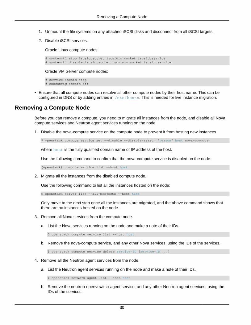
Removing a Compute Node
30
1. Unmount the file systems on any attached iSCSI disks and disconnect from all iSCSI targets.
2. Disable iSCSI services.
Oracle Linux compute nodes:
# systemctl stop iscsid.socket iscsiuio.socket iscsid.service # systemctl disable iscsid.socket iscsiuio.socket iscsid.service
Oracle VM Server compute nodes:
# service iscsid stop# chkconfig iscsid off
• Ensure that all compute nodes can resolve all other compute nodes by their host name. This can beconfigured in DNS or by adding entries in /etc/hosts. This is needed for live instance migration.
Removing a Compute Node
Before you can remove a compute, you need to migrate all instances from the node, and disable all Novacompute services and Neutron agent services running on the node.
1. Disable the nova-compute service on the compute node to prevent it from hosting new instances.
$ openstack compute service set --disable --disable-reason "reason" host nova-compute
where host is the fully qualified domain name or IP address of the host.
Use the following command to confirm that the nova-compute service is disabled on the node:
(openstack) compute service list --host host
2. Migrate all the instances from the disabled compute node.
Use the following command to list all the instances hosted on the node:
$ openstack server list --all-projects --host host
Only move to the next step once all the instances are migrated, and the above command shows thatthere are no instances hosted on the node.
3. Remove all Nova services from the compute node.
a. List the Nova services running on the node and make a note of their IDs.
$ openstack compute service list --host host
b. Remove the nova-compute service, and any other Nova services, using the IDs of the services.
$ openstack compute service delete service-ID [service-ID ...]
4. Remove all the Neutron agent services from the node.
a. List the Neutron agent services running on the node and make a note of their IDs.
$ openstack network agent list --host host
b. Remove the neutron-openvswitch-agent service, and any other Neutron agent services, using theIDs of the services.
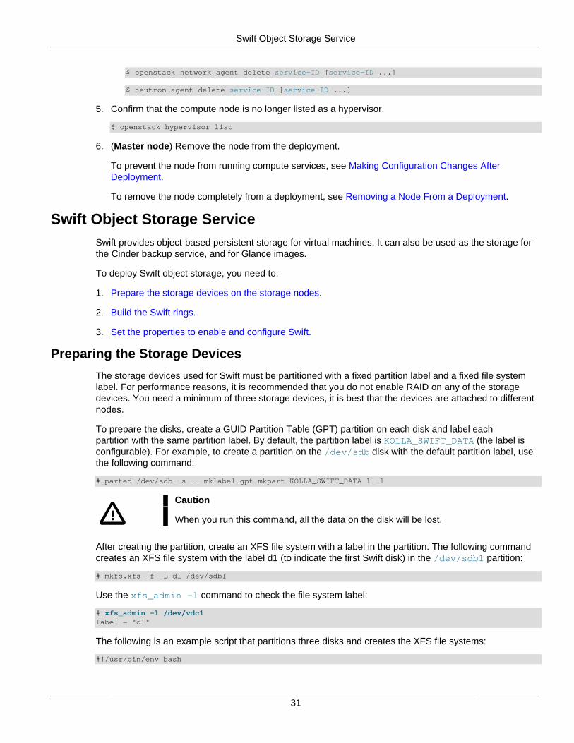
Swift Object Storage Service
31
$ openstack network agent delete service-ID [service-ID ...]
$ neutron agent-delete service-ID [service-ID ...]
5. Confirm that the compute node is no longer listed as a hypervisor.
$ openstack hypervisor list
6. (Master node) Remove the node from the deployment.
To prevent the node from running compute services, see Making Configuration Changes AfterDeployment.
To remove the node completely from a deployment, see Removing a Node From a Deployment.
Swift Object Storage ServiceSwift provides object-based persistent storage for virtual machines. It can also be used as the storage forthe Cinder backup service, and for Glance images.
To deploy Swift object storage, you need to:
1. Prepare the storage devices on the storage nodes.
2. Build the Swift rings.
3. Set the properties to enable and configure Swift.
Preparing the Storage Devices
The storage devices used for Swift must be partitioned with a fixed partition label and a fixed file systemlabel. For performance reasons, it is recommended that you do not enable RAID on any of the storagedevices. You need a minimum of three storage devices, it is best that the devices are attached to differentnodes.
To prepare the disks, create a GUID Partition Table (GPT) partition on each disk and label eachpartition with the same partition label. By default, the partition label is KOLLA_SWIFT_DATA (the label isconfigurable). For example, to create a partition on the /dev/sdb disk with the default partition label, usethe following command:
# parted /dev/sdb -s -- mklabel gpt mkpart KOLLA_SWIFT_DATA 1 -1
Caution
When you run this command, all the data on the disk will be lost.
After creating the partition, create an XFS file system with a label in the partition. The following commandcreates an XFS file system with the label d1 (to indicate the first Swift disk) in the /dev/sdb1 partition:
# mkfs.xfs -f -L d1 /dev/sdb1
Use the xfs_admin -l command to check the file system label:
# xfs_admin -l /dev/vdc1label = "d1"
The following is an example script that partitions three disks and creates the XFS file systems:
#!/usr/bin/env bash
Building the Swift Rings
32
index=0for d in sdc sdd sde; do parted /dev/${d} -s -- mklabel gpt mkpart KOLLA_SWIFT_DATA 1 -1 sudo mkfs.xfs -f -L d${index} /dev/${d}1 (( index++ ))done
The Swift storage devices are automatically mounted under /srv/node. Create this mount point manuallyon each storage node:
# mkdir -p /srv/node
If the mlocate package is installed on the storage nodes, it is recommended that you add /srv/node tothe PRUNEPATHS entry in /etc/updatedb.conf to prevent updatedb from indexing directories below /srv/node.
Building the Swift Rings
You need to create the Swift rings so that each storage node knows where to store the objects. The pathto an object stored in Swift consists of an account (tenant or project), a container, and the object itself.Accounts and containers are the means by which objects are organized and replicated in the storage.Swift rings are databases, as follows:
• The Swift account servers use the account ring to manage the list of containers for each account.
• The Swift container servers use the container ring to manage the list of objects in each container.
• The Swift object servers use the object ring to manage the list of where objects are located on thestorage devices.
Swift storage is organized into regions (for geographical separation), which contain zones (for availability,such as a building, a data center, or a server rack), which contain storage servers, and disks (inside orattached to the storage servers).
For more information about the Swift rings and how storage is organized, see the OpenStack Swiftdocumentation:
• https://docs.openstack.org/swift/pike/overview_ring.html
• https://docs.openstack.org/swift/pike/admin_guide.html#managing-the-rings
• https://docs.openstack.org/swift/pike/admin/objectstorage-components.html
Before you deploy Swift services, you build the initial Swift rings manually on the master node, using theswift-ring-builder utility. To avoid any issues with software versions, it is best to run the swift-ring-builder utility in a Docker container using the ol-openstack-swift-base image that isincluded with the Oracle OpenStack images. To do this:
• The Docker Engine must be set up and running on the master node, see Preparing Oracle Linux Nodesin the Oracle OpenStack Installation and Deployment Guide for the required configuration.
• The Oracle OpenStack images must be loaded in a Docker registry.
For ease of management, it is recommended that you use a script to create the Swift rings. An examplescript is included in this section. The user that runs the script must be a member of the Docker group (sothat they can run Docker commands). It is best that this user is also a member of the kolla group.
If you are using the Oracle Container Registry, you might need to sign in at https://container-registry.oracle.com before you can run the swift-ring-builder utility. After you accept the terms, you
Building the Swift Rings
33
also need to register your login credentials for the Oracle Container Registry with Docker so that you canpull (download) images:
$ docker login -u user-name container-registry.oracle.comPassword:Login Succeeded
The Swift rings are created as custom configuration files in the /etc/kolla/config/swift directory onthe master node. When you deploy the Swift service, the rings are copied to the storage nodes. You haveto manually create the /etc/kolla/config/swift directory on the master node:
# mkdir -p /etc/kolla/config/swift
The example script creates the following files:
• account.builder and account.ring.gz for the account ring.
• container.builder and container.ring.gz for the container ring.
• object.builder and object.ring.gz for the object ring.
You must use these file names in your own scripts.
Caution
Make sure you keep a backup of the .builder files, as you need these files if youwant to make changes to the rings.
Example 2.1 Example Swift Ring Configuration Script
The following is an example configuration script for setting up the Swift rings by running the swift-ring-builder utility in a Docker container. The script configures three nodes with three disks each. Note thefollowing:
• The STORAGE_NODES array stores the IP addresses of the storage nodes (three storage nodes in thisexample). Replace node_IP with the IP addresses of your nodes.
• The SWIFT_BASE_IMAGE is the full name of the image that is used to pull the Swift base image from theregistry.
• The REGISTRY variable contains the host name and port of the Docker registry that contains the OracleOpenStack images. If you are using the Oracle Container Registry, set this variable to container-registry.oracle.com.
• The NAMESPACE variable contains the namespace used to store the Oracle OpenStack images in theDocker registry. If you are using the Oracle Container Registry, set this variable to openstack. If youare using Docker Hub, set this variable to oracle.
• The IMAGE variable contains the name of the Oracle OpenStack Swift base image, ol-openstack-swift-base.
• The TAG variable contains the Oracle OpenStack release number such as 4.0.
• The .builder files are created using a 10 3 1 specification, which configures 1024 (2^10) maximumpartitions, 3 replicas of each object, and 1 hour minimum time between moving a partition more thanonce. A partition is a directory on a storage device rather than a hard disk division. It is recommended tohave a minimum of three replicas.
• The script assumes the default Swift ports 6000 (object server), 6001 (account server) and 6002(container server) are used. The ports are configurable.
Building the Swift Rings
34
• The script assigns the same weight (1) to balance the distribution of partitions on drives across thecluster. This assumes all the disks are the same size.
#!/usr/bin/env bash
STORAGE_NODES=(node1_IP node2_IP node3_IP)
REGISTRY=registry_hostname:registry_portNAMESPACE=namespaceIMAGE=ol-openstack-swift-baseTAG=openstack_releaseSWIFT_BASE_IMAGE=${REGISTRY}/${NAMESPACE}/${IMAGE}:${TAG}
# Create the config directory mkdir -p /etc/kolla/config/swift
# Create the object ringdocker run \ --rm \ -v /etc/kolla/config/swift/:/etc/kolla/config/swift/ \ $SWIFT_BASE_IMAGE \ swift-ring-builder \ /etc/kolla/config/swift/object.builder create 10 3 1
for node in ${STORAGE_NODES[@]}; do for i in {0..2}; do docker run \ --rm \ -v /etc/kolla/config/swift/:/etc/kolla/config/swift/ \ $SWIFT_BASE_IMAGE \ swift-ring-builder \ /etc/kolla/config/swift/object.builder add r1z1-${node}:6000/d${i} 1; donedone
# Create the account ringdocker run \ --rm \ -v /etc/kolla/config/swift/:/etc/kolla/config/swift/ \ $SWIFT_BASE_IMAGE \ swift-ring-builder \ /etc/kolla/config/swift/account.builder create 10 3 1
for node in ${STORAGE_NODES[@]}; do for i in {0..2}; do docker run \ --rm \ -v /etc/kolla/config/swift/:/etc/kolla/config/swift/ \ $SWIFT_BASE_IMAGE \ swift-ring-builder \ /etc/kolla/config/swift/account.builder add r1z1-${node}:6001/d${i} 1; donedone
# Create the container ringdocker run \ --rm \ -v /etc/kolla/config/swift/:/etc/kolla/config/swift/ \ $SWIFT_BASE_IMAGE \ swift-ring-builder \ /etc/kolla/config/swift/container.builder create 10 3 1
for node in ${STORAGE_NODES[@]}; do for i in {0..2}; do docker run \ --rm \ -v /etc/kolla/config/swift/:/etc/kolla/config/swift/ \
Enabling and Configuring Swift
35
$SWIFT_BASE_IMAGE \ swift-ring-builder \ /etc/kolla/config/swift/container.builder add r1z1-${node}:6002/d${i} 1; donedone
# Rebalance the ringsfor ring in object account container; do docker run \ --rm \ -v /etc/kolla/config/swift/:/etc/kolla/config/swift/ \ $SWIFT_BASE_IMAGE \ swift-ring-builder \ /etc/kolla/config/swift/${ring}.builder rebalance;done
Enabling and Configuring Swift
Perform the following steps on the master node.
1. Enable the Swift service.
$ kollacli property set enable_swift yes
2. Set the Swift hash path prefix and suffix.
The hash path prefix and suffix are random numbers that are used in Swift's hashing process whenstoring objects.
To set the prefix and suffix, use the following commands
$ kollacli password set swift_hash_path_prefix$ kollacli password set swift_hash_path_suffix
The kollacli password set command prompts you for the password (the prefix or suffix), and toconfirm the password. The password value is not displayed on screen. The values for the prefix andsuffix must be different. Use a cryptographically secure random number generator to generate thenumber, for example:
# openssl rand –hex 10
Alternatively, you can use the kollacli password init command to set secure random numbersfor the prefix and suffix. However, this command also configures all the passwords that have not beenset for individual services, which may not be want you want.
Caution
For security reasons, keep these values secret. The prefix and suffix values arestored in the /etc/kolla/passwords.yml file. Only the kolla user andmembers of the kolla group have read-write access to this file.
Do not lose these values. Ensure you have a secure backup of thepasswords.yml file.
Once you have deployed Swift, you must not change these values.
3. Configure the Swift storage devices to use.
The default property settings (shown below) are sufficient. Use the swift_devices_name property tospecify the partition label if you used a different label.

Enabling and Configuring Swift
36
$ kollacli property set swift_devices_match_mode strict$ kollacli property set swift_devices_name KOLLA_SWIFT_DATA
Caution
Do not change the swift_devices_mount_point property from the defaultvalue of /srv/node.
37
Chapter 3 Additional Component Configuration
Table of ContentsCentral Logging (Fluentd, Elasticsearch and Kibana) ......................................................................... 37Ceph Storage ................................................................................................................................... 38
Ceph Storage Partitioning ......................................................................................................... 39Setting up Ceph Storage .......................................................................................................... 42Configuring Ceph Networks ...................................................................................................... 44Adding a Ceph Node ................................................................................................................ 45Removing a Ceph OSD Node (Storage) .................................................................................... 45Removing a Ceph Mon Node (Controller) .................................................................................. 46Running Ceph Commands ........................................................................................................ 47
MySQL Database ............................................................................................................................. 47Setting MySQL NDB Cluster Global Options .............................................................................. 47Setting MySQL NDB Cluster Configuration Parameters .............................................................. 48Configuring the Service Databases ........................................................................................... 49Backing Up and Restoring the MySQL Database ....................................................................... 50
Service Endpoint High Availability (Keepalived and HAProxy) ............................................................. 55Time Synchronization (Chrony) ......................................................................................................... 57
In addition to the OpenStack services, an OpenStack deployment requires several other components inorder to operate, such as a database to store information and a message queue to coordinate operationsand status information among services. These components are deployed as Docker containers on nodes.This section describes some of the configuration options for these general components.
Central Logging (Fluentd, Elasticsearch and Kibana)
Central logging consolidates and indexes the log files from the OpenStack Docker containers on all nodesso that you can search the logs from a single location using a web browser. Central logging is enabled bydefault.
Central logging makes use of the following components:
• Fluentd: This is an open source data collector. Fluentd collects the OpenStack logs and forwards thedata to Elasticsearch.
• Elasticsearch: This is a distributed, open source search and analytics engine. Elasticsearch is used tostore and index the processed log files, and to provide full-text search capabilities.
• Kibana: This is an open source data visualization platform. Kibana is used to search the OpenStack logsin Elasticsearch, and to create graphical representations of the data.
Fluentd is always deployed and it runs on every node in the deployment. All the log files that are processedby Fluentd are collected on each node in the/var/lib/docker/volumes/kolla_logs/_data directory. When central logging is enabled,Elasticsearch and Kibana run on the controller nodes.
Kibana has a web interface where you can search the logs, and create graphics and dashboards. The webinterface is available at http://kibana-address:5601, where kibana-address is the internal or externalvirtual IP (VIP) address, or the internal or external fully qualified DNS name, used for your OpenStack
Using the Kibana Web Interface
38
deployment. See Configuring OpenStack Service Endpoints for more details about VIP addresses andDNS names. The port is configurable (the kibana_port property).
Access to the kibana web interface is protected by HTTP Basic Authentication (configured in the HAProxyconfiguration). The default user name is kibana (configurable with the kibana_user property).You configure the password (kibana_password) with either the kollacli password set or thekollacli password init command. The password is stored in the /etc/kolla/passwords.ymlfile on the master node.
To disable central logging before you deploy OpenStack:
$ kollacli property set enable_central_logging no
If you disable central logging, you can examine the log files on each node in the/var/lib/docker/volumes/kolla_logs/_data directory. You can also collect the log files fromthe nodes, as described in Collecting the Log Files in the Oracle OpenStack Installation and DeploymentGuide.
Using the Kibana Web Interface
After you have deployed OpenStack services with central logging enabled, you need to log in to the Kibanaweb interface so that you can search and view the logs, and create data visualizations.
In a web browser, go to http://kibana-address:5601, where kibana-address is the internal or externalvirtual IP (VIP) address, or the internal or external fully qualified DNS name, used for your OpenStackdeployment. See Configuring OpenStack Service Endpoints for more details about VIP addresses andDNS names. When prompted, log in with the Kibana user name and password.
Kibana supports most modern web browsers.See https://www.elastic.co/support/matrix#matrix_browsers for details of the supported browsers forKibana version 4.
The Kibana web interface is not shipped with any preconfigured searches, visualizations or dashboards foruse with OpenStack. You might want to configure these for use in your deployment, as follows:
• The Discover tab enables you to search the logs, filter the results on the available log fields, and viewmatching individual log entries.
• The Visualize tab enables you to create a variety of charts based on searches of the logs.
• The Dashboard tab enables you to create dashboards that use your saved searches and visualizations.
In the Kibana web interface, the time period filter you select in the top right-hand corner controls theamount of data shown in any searches, visualizations, or dashboards.
You can save searches, visualizations, and dashboards so that they can be used again in another Kibanasession. You can also export them so that they can imported for use in another OpenStack deployment(select the Settings tab and then the Objects tab) .
For more detailed information, see the Kibana User Guide at https://www.elastic.co/guide/en/kibana/current/index.html.
Ceph StorageCeph is a scalable, distributed storage system, comprised of an object store, block store, and a POSIX-compliant distributed file system. Ceph can be used for ephemeral storage for Nova instances, and as thestorage for Glance images (see Glance Image Service.
Ceph Storage Partitioning
39
Ceph is based on RADOS: Reliable Autonomic Distributed Object Store. RADOS distributes objectsacross the storage cluster and replicates objects for fault tolerance. The following RADOS components areincluded with Oracle OpenStack:
• Ceph Object Storage Device (Ceph OSD) Daemon. The Ceph OSD storage daemon. The Ceph OSDcontainer (ceph_osd) is deployed to storage nodes. You must attach and label a disk or LUN on eachstorage node for use with Ceph OSD. It is recommended you have at least three storage nodes for HighAvailability.
• Ceph Monitor (Ceph MON). A daemon that handles all communications with external applicationsand clients. It checks the state and the consistency of the data, and tracks active and failed nodes inthe Ceph storage cluster. The Ceph MON container (ceph_mon) is deployed to control nodes. It isrecommended you have at least three control nodes for High Availability.
Virtual machine instances deployed to Oracle VM Server with Ceph enabled must be Hardware Virtualized.That is, you must set the Glance image vm_mode property to hvm. For example:
$ openstack image create --private --disk-format raw --container-format bare \--file mydisk.img --property vm_mode=hvm MyImage
For more information on Ceph, see the Ceph Storage for Oracle® Linux Release Notes at:
https://docs.oracle.com/cd/E52668_01/E66514/html/index.html
Ceph Storage Partitioning
Ceph requires two partitions on each storage node for an OSD: a small partition (usually around 5GB) fora journal, and another using the remaining space for the Ceph data. These partitions can be on the samedisk or LUN (co-located), or the data can be on one partition, and the journal stored on a solid state drive(SSD) or in memory (external journals).
The location of the OSD journal and data partitions is set using GPT partition labels. You set labels onpartitions on the storage node before you deploy OpenStack. The deployment looks for partitions with theappropriate Ceph-related labels, and wipes and reformats the disks, and then partitions them as requiredfor the Ceph deployment.
You set one label for a co-located deployment, or two labels for external journals. You can set additionalpartition labels for the Ceph cache tiering feature. The labels are described in the following table.
Table 3.1 Ceph Disk Provisioning
Partition Label Disk Provisioning
KOLLA_CEPH_OSD_BOOTSTRAP Used for co-located journals and data.
If a partition is found with this label, the disk is wiped,and partitioned into two partitions, the first being a small5GB partition for the journal, and the second with theremaining space for the data.
KOLLA_CEPH_OSD_BOOTSTRAP_TOKEN
KOLLA_CEPH_OSD_BOOTSTRAP_TOKEN_J
Used for external journals.
If these two partition labels are found, the data andjournal are deployed to these partitions separately. Thelabel ending with J is used for the journal.
TOKEN can be any alphanumeric string. For example:
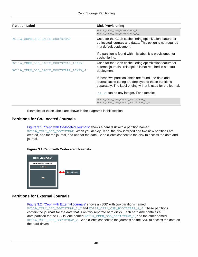
Ceph Storage Partitioning
40
Partition Label Disk ProvisioningKOLLA_CEPH_OSD_BOOTSTRAP_1KOLLA_CEPH_OSD_BOOTSTRAP_1_J
KOLLA_CEPH_OSD_CACHE_BOOTSTRAP Used for the Ceph cache tiering optimization feature forco-located journals and datas. This option is not requiredin a default deployment.
If a partition is found with this label, it is provisioned forcache tiering.
KOLLA_CEPH_OSD_CACHE_BOOTSTRAP_TOKEN
KOLLA_CEPH_OSD_CACHE_BOOTSTRAP_TOKEN_J
Used for the Ceph cache tiering optimization feature forexternal journals. This option is not required in a defaultdeployment.
If these two partition labels are found, the data andjournal cache tiering are deployed to these partitionsseparately. The label ending with J is used for the journal.
TOKEN can be any integer. For example:
KOLLA_CEPH_OSD_CACHE_BOOTSTRAP_1KOLLA_CEPH_OSD_CACHE_BOOTSTRAP_1_J
Examples of these labels are shown in the diagrams in this section.
Partitions for Co-Located Journals
Figure 3.1, “Ceph with Co-located Journals” shows a hard disk with a partition namedKOLLA_CEPH_OSD_BOOTSTRAP. When you deploy Ceph, the disk is wiped and two new partitions arecreated, one for the journal, and one for the data. Ceph clients connect to the disk to access the data andjournal.
Figure 3.1 Ceph with Co-located Journals
Partitions for External Journals
Figure 3.2, “Ceph with External Journals” shows an SSD with two partitions namedKOLLA_CEPH_OSD_BOOTSTRAP_1_J and KOLLA_CEPH_OSD_BOOTSTRAP_2_J. These partitionscontain the journals for the data that is on two separate hard disks. Each hard disk contains adata partition for the OSDs, one named KOLLA_CEPH_OSD_BOOTSTRAP_1, and the other namedKOLLA_CEPH_OSD_BOOTSTRAP_2. Ceph clients connect to the journals on the SSD to access the data onthe hard drives.
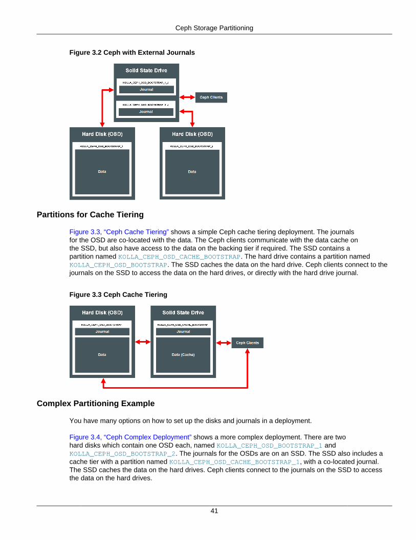
Ceph Storage Partitioning
41
Figure 3.2 Ceph with External Journals
Partitions for Cache Tiering
Figure 3.3, “Ceph Cache Tiering” shows a simple Ceph cache tiering deployment. The journalsfor the OSD are co-located with the data. The Ceph clients communicate with the data cache onthe SSD, but also have access to the data on the backing tier if required. The SSD contains apartition named KOLLA_CEPH_OSD_CACHE_BOOTSTRAP. The hard drive contains a partition namedKOLLA_CEPH_OSD_BOOTSTRAP. The SSD caches the data on the hard drive. Ceph clients connect to thejournals on the SSD to access the data on the hard drives, or directly with the hard drive journal.
Figure 3.3 Ceph Cache Tiering
Complex Partitioning Example
You have many options on how to set up the disks and journals in a deployment.
Figure 3.4, “Ceph Complex Deployment” shows a more complex deployment. There are twohard disks which contain one OSD each, named KOLLA_CEPH_OSD_BOOTSTRAP_1 andKOLLA_CEPH_OSD_BOOTSTRAP_2. The journals for the OSDs are on an SSD. The SSD also includes acache tier with a partition named KOLLA_CEPH_OSD_CACHE_BOOTSTRAP_1, with a co-located journal.The SSD caches the data on the hard drives. Ceph clients connect to the journals on the SSD to accessthe data on the hard drives.
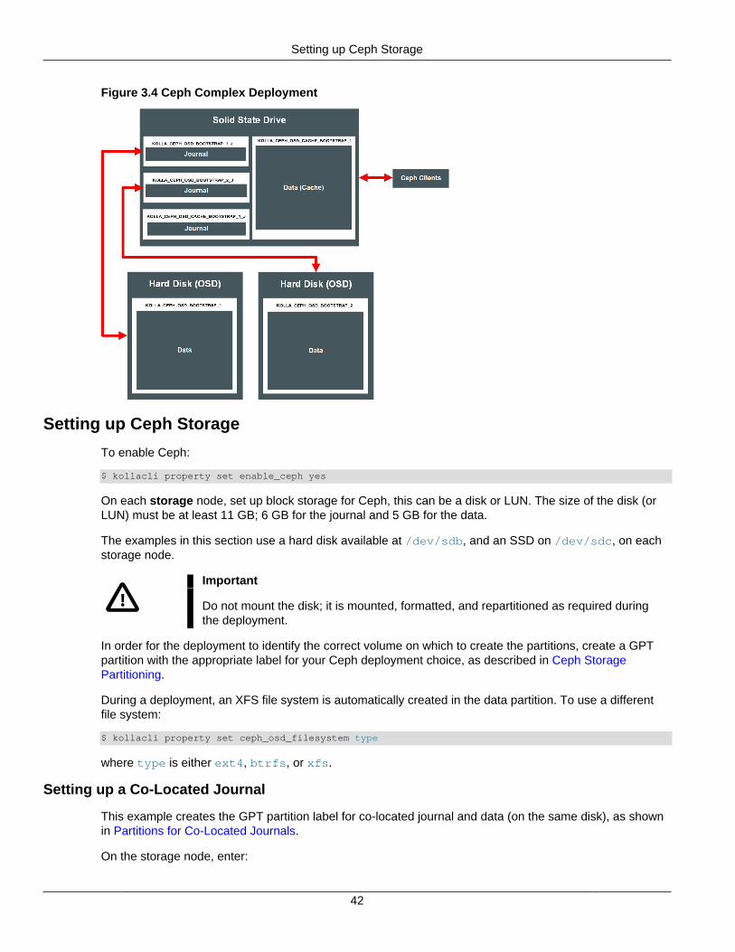
Setting up Ceph Storage
42
Figure 3.4 Ceph Complex Deployment
Setting up Ceph Storage
To enable Ceph:
$ kollacli property set enable_ceph yes
On each storage node, set up block storage for Ceph, this can be a disk or LUN. The size of the disk (orLUN) must be at least 11 GB; 6 GB for the journal and 5 GB for the data.
The examples in this section use a hard disk available at /dev/sdb, and an SSD on /dev/sdc, on eachstorage node.
Important
Do not mount the disk; it is mounted, formatted, and repartitioned as required duringthe deployment.
In order for the deployment to identify the correct volume on which to create the partitions, create a GPTpartition with the appropriate label for your Ceph deployment choice, as described in Ceph StoragePartitioning.
During a deployment, an XFS file system is automatically created in the data partition. To use a differentfile system:
$ kollacli property set ceph_osd_filesystem type
where type is either ext4, btrfs, or xfs.
Setting up a Co-Located Journal
This example creates the GPT partition label for co-located journal and data (on the same disk), as shownin Partitions for Co-Located Journals.
On the storage node, enter:

Setting up Ceph Storage
43
# parted /dev/sdb -s -- mklabel gpt mkpart KOLLA_CEPH_OSD_BOOTSTRAP 1 -1
If the deployment finds a partition with the KOLLA_CEPH_OSD_BOOTSTRAP label, the disk is wiped andre-partitioned to one small (6 GB) partition for the journal, and the remaining space on the disk is used as apartition for the data.
If there are other partitions on the disk, the deployment fails in order to avoid any unexpected data loss.Make sure you only create a partition with the KOLLA_CEPH_OSD_BOOTSTRAP label, and no otherpartitions exist.
If you want to override this behavior, you can set the following property to ignore the warning and wipe thedisk (including any other partitions):
$ kollacli property set ceph_osd_wipe_disk yes-i-really-mean-it
Setting up an External Journal
If you want to separate the journal and data partitions and use external journals, create two partitions. Thedata is on the hard disk, and the journal is on the SSD, as shown in Partitions for External Journals. Tolabel the data partition on the hard disk, use:
# parted /dev/sdb -s -- mklabel gpt mkpart KOLLA_CEPH_OSD_BOOTSTRAP_1 1 -1
Create a smaller (at least 6 GB) partition for the journal on the SSD with the appropriate label for the OSD:
# parted /dev/sdc -s -- mkpart KOLLA_CEPH_OSD_BOOTSTRAP_1_J start_MB end_MB
Make sure the token in both the data and journal labels matches for each OSD, in this case, 1.
Setting up Cache Tiering
The Ceph cache tiering I/O optimization feature creates two Ceph pools: one for the backing data storage,and another as the data cache. The pools are set up automatically during the deployment when you enableCeph cache tiering.
Cache tiering involves using fast storage devices (such as SSDs) as a cache tier, and slower/cheaperdevices as a storage tier. In some situations, cache tiering may be a slower deployment model. Whethercache tiering is useful to your deployment depends on your workload, as there is a performance costassociated with moving objects into or out of the cache.
To enable Ceph cache tiering:
$ kollacli property set ceph_enable_cache yes
You must also set up the Ceph cache tiering partition labels on the storage nodes. These partitions are inaddition to the partitions you set up for the OSDs, as shown in Partitions for Cache Tiering.
Usually, you set up cache tiering on a fast drive, such as an SSD. You can co-locate or use externaljournals. The following examples set up the cache tier on an SSD at /dev/sdc.
For co-located journal and data on the SSD, use:
# parted /dev/sdc -s -- mklabel gpt mkpart KOLLA_CEPH_OSD_CACHE_BOOTSTRAP 1 -1
Alternatively, you can create a partition for the cache and journal, instead of using the entire disk with:
# parted /dev/sdc -s -- mkpart KOLLA_CEPH_OSD_CACHE_BOOTSTRAP start_MB end_MB
To use separate cache journal and data partitions (external journals) on the SSD, use:
Configuring Ceph Networks
44
# parted /dev/sdc -s -- mkpart KOLLA_CEPH_OSD_CACHE_BOOTSTRAP_1 start_MB end_MB# parted /dev/sdc -s -- mkpart KOLLA_CEPH_OSD_CACHE_BOOTSTRAP_1_J start_MB end_MB
For more information on cache tiering, see the Ceph documentation:
http://docs.ceph.com/docs/master/rados/operations/cache-tiering/
Setting up an Erasure Code Pool
A Ceph pool, by default, is created as a replicated pool, meaning every object is copied to multiple disks.You can set a Ceph pool to use erasure code instead to save disk space.
In order to use erasure code pools, you must also set up a cache tier. For information on setting up acache tier, see Setting up Cache Tiering.
To use an erasure code pool, edit the ceph_pool_type property:
$ kollacli property set ceph_pool_type erasure
To change the erasure profile, edit the ceph_erasure_profile property:
$ kollacli property set ceph_erasure_profile profile
The default value is k=4 m=2 ruleset-failure-domain=host.
For more information on the Ceph erasure code feature and profiles, see the Ceph documentation at:
http://docs.ceph.com/docs/hammer/rados/operations/erasure-code/
Setting up Oracle VM Server as a Ceph OSD
Setting up Oracle VM Server as a Ceph OSD node enables you to make use of the local storage on anOracle VM Server host. You can create the appropriate partition labels on any extra storage and use thepartitions as a Ceph OSD.
To set up Oracle VM Server as a Ceph OSD:
1. Prepare an Oracle VM Server for a deployment.
See Preparing Oracle VM Server Nodes in the Oracle OpenStack Installation and Deployment Guidefor information on setting up an Oracle VM Server.
2. Log into the Oracle VM Server as the root user.
3. Set up the Ceph OSD partition label(s) as described in Setting up Ceph Storage.
The following example creates the GPT partition label for co-located journal and data (on the samedisk), as shown in in Partitions for Co-Located Journals.
# parted /dev/sdb -s -- mklabel gpt mkpart KOLLA_CEPH_OSD_BOOTSTRAP 1 -1
4. Add the Oracle VM Server to the storage deployment group as described in Adding a Ceph Node.
Configuring Ceph Networks
Ceph uses two networks, a public network and a cluster network.
The public network is used for all communication with Ceph. All Ceph nodes must have a networkinterface on this network. You specify the network interface by setting the storage_interface property.By default, the value of the network_interface property is used.
Adding a Ceph Node
45
The cluster network is used for heartbeat communication and object replication between OSDs. All CephOSD nodes must have a network interface on this network. You specify the network interface by setting thecluster_interface property. By default, the value of the network_interface property is used.
For security and performance reasons, it is recommended to configure two separate networks for Ceph.The cluster network should not be publicly accessible.
Adding a Ceph Node
To add a Ceph MON (monitor) node to the Ceph cluster, add the node to the control deployment group.For example, for a node named control03:
$ kollacli host add control03$ kollacli group addhost control control03
To add a Ceph OSD storage node, you must first configure the partition(s) or disk as outlined in Settingup Ceph Storage. You must then add the node to the storage deployment group. For example, for a nodenamed storage03:
$ kollacli host add storage03$ kollacli group addhost storage storage03
To deploy the node(s):
$ kollacli reconfigure
If you are using the Oracle Container Registry, you might need to sign in athttps://container-registry.oracle.com and accept the Oracle Standard Terms and Restrictions for the Oraclesoftware images (see Choosing a Docker Registry) before you deploy.
Removing a Ceph OSD Node (Storage)
To remove a Ceph OSD node (storage), first migrate the data from the node, and then remove the nodefrom the Ceph cluster.
To remove a Ceph OSD node:
1. (Controller node) Find the ID of the Ceph OSD node you want to remove.
# docker exec -it ceph_mon ceph osd tree# id weight type name up/down reweight-1 3 root default-2 1 host 192.168.11.90 1 osd.0 up 1 -3 1 host 192.168.11.121 1 osd.1 up 1 -4 1 host 192.168.11.82 1 osd.2 up 1
In this example, the OSD on the storage node with the host IP address of 192.168.11.8 is to beremoved. This OSD has an ID of 2.
2. (Controller node) Mark the OSD node as out of the Ceph cluster.
# docker exec -it ceph_mon ceph osd out 2
The data on the OSD is automatically migrated to another OSD (storage node) in the Ceph cluster.Wait for the data migration to complete. You can monitor the data migration with the command:
# docker exec -it ceph_mon ceph -w
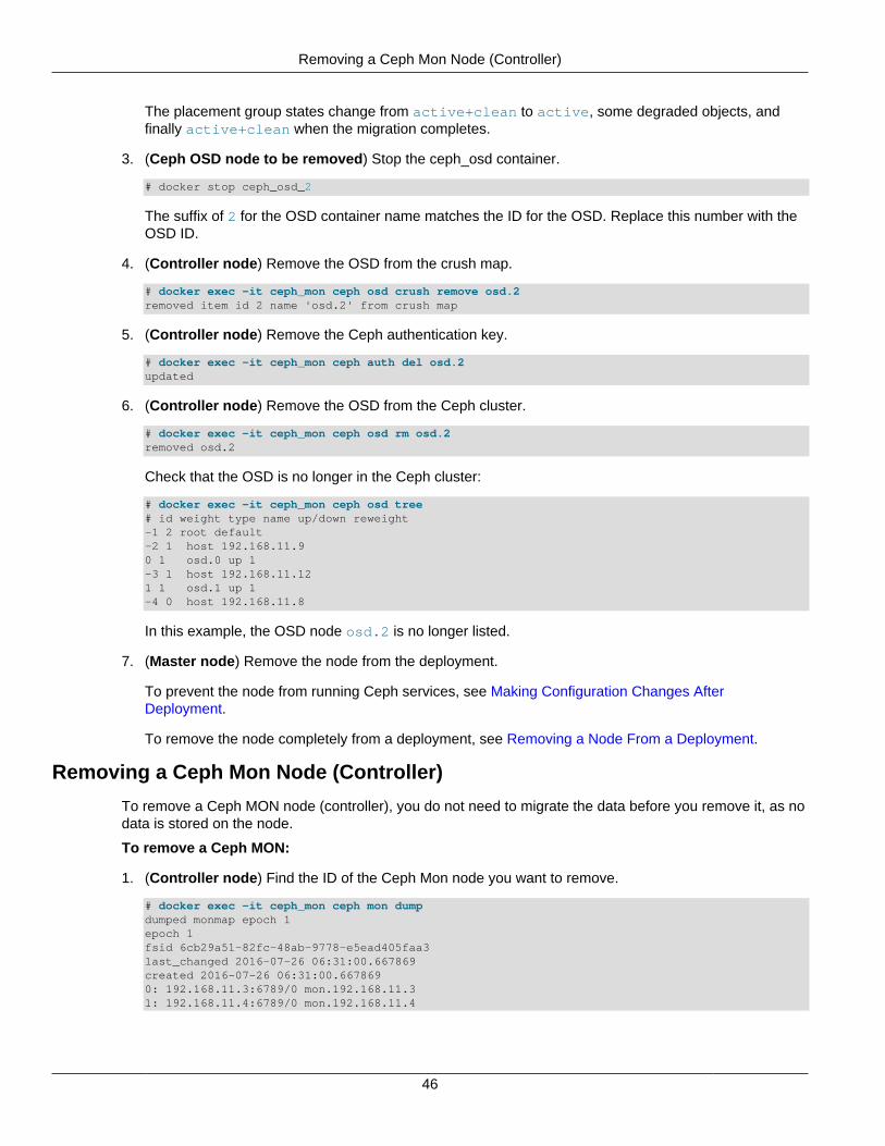
Removing a Ceph Mon Node (Controller)
46
The placement group states change from active+clean to active, some degraded objects, andfinally active+clean when the migration completes.
3. (Ceph OSD node to be removed) Stop the ceph_osd container.
# docker stop ceph_osd_2
The suffix of 2 for the OSD container name matches the ID for the OSD. Replace this number with theOSD ID.
4. (Controller node) Remove the OSD from the crush map.
# docker exec -it ceph_mon ceph osd crush remove osd.2removed item id 2 name 'osd.2' from crush map
5. (Controller node) Remove the Ceph authentication key.
# docker exec -it ceph_mon ceph auth del osd.2updated
6. (Controller node) Remove the OSD from the Ceph cluster.
# docker exec -it ceph_mon ceph osd rm osd.2removed osd.2
Check that the OSD is no longer in the Ceph cluster:
# docker exec -it ceph_mon ceph osd tree# id weight type name up/down reweight-1 2 root default-2 1 host 192.168.11.90 1 osd.0 up 1 -3 1 host 192.168.11.121 1 osd.1 up 1 -4 0 host 192.168.11.8
In this example, the OSD node osd.2 is no longer listed.
7. (Master node) Remove the node from the deployment.
To prevent the node from running Ceph services, see Making Configuration Changes AfterDeployment.
To remove the node completely from a deployment, see Removing a Node From a Deployment.
Removing a Ceph Mon Node (Controller)
To remove a Ceph MON node (controller), you do not need to migrate the data before you remove it, as nodata is stored on the node.
To remove a Ceph MON:
1. (Controller node) Find the ID of the Ceph Mon node you want to remove.
# docker exec -it ceph_mon ceph mon dumpdumped monmap epoch 1epoch 1fsid 6cb29a51-82fc-48ab-9778-e5ead405faa3last_changed 2016-07-26 06:31:00.667869created 2016-07-26 06:31:00.6678690: 192.168.11.3:6789/0 mon.192.168.11.31: 192.168.11.4:6789/0 mon.192.168.11.4
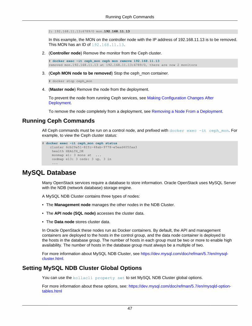
Running Ceph Commands
47
2: 192.168.11.13:6789/0 mon.192.168.11.13
In this example, the MON on the controller node with the IP address of 192.168.11.13 is to be removed.This MON has an ID of 192.168.11.13.
2. (Controller node) Remove the monitor from the Ceph cluster.
# docker exec -it ceph_mon ceph mon remove 192.168.11.13removed mon.192.168.11.13 at 192.168.11.13:6789/0, there are now 2 monitors
3. (Ceph MON node to be removed) Stop the ceph_mon container.
# docker stop ceph_mon
4. (Master node) Remove the node from the deployment.
To prevent the node from running Ceph services, see Making Configuration Changes AfterDeployment.
To remove the node completely from a deployment, see Removing a Node From a Deployment.
Running Ceph Commands
All Ceph commands must be run on a control node, and prefixed with docker exec -it ceph_mon. Forexample, to view the Ceph cluster status:
# docker exec -it ceph_mon ceph status cluster 6cb29a51-82fc-48ab-9778-e5ead405faa3 health HEALTH_OK monmap e1: 3 mons at ... osdmap e13: 3 osds: 3 up, 3 in ...
MySQL DatabaseMany OpenStack services require a database to store information. Oracle OpenStack uses MySQL Serverwith the NDB (network database) storage engine.
A MySQL NDB Cluster contains three types of nodes:
• The Management node manages the other nodes in the NDB Cluster.
• The API node (SQL node) accesses the cluster data.
• The Data node stores cluster data.
In Oracle OpenStack these nodes run as Docker containers. By default, the API and managementcontainers are deployed to the hosts in the control group, and the data node container is deployed tothe hosts in the database group. The number of hosts in each group must be two or more to enable highavailability. The number of hosts in the database group must always be a multiple of two.
For more information about MySQL NDB Cluster, see https://dev.mysql.com/doc/refman/5.7/en/mysql-cluster.html.
Setting MySQL NDB Cluster Global Options
You can use the kollacli property set to set MySQL NDB Cluster global options.
For more information about these options, see: https://dev.mysql.com/doc/refman/5.7/en/mysqld-option-tables.html
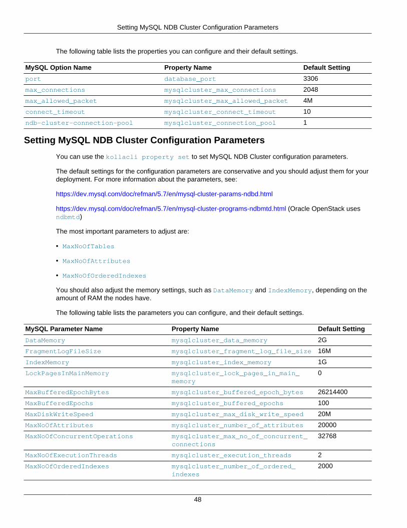
Setting MySQL NDB Cluster Configuration Parameters
48
The following table lists the properties you can configure and their default settings.
MySQL Option Name Property Name Default Setting
port database_port 3306
max_connections mysqlcluster_max_connections 2048
max_allowed_packet mysqlcluster_max_allowed_packet 4M
connect_timeout mysqlcluster_connect_timeout 10
ndb-cluster-connection-pool mysqlcluster_connection_pool 1
Setting MySQL NDB Cluster Configuration Parameters
You can use the kollacli property set to set MySQL NDB Cluster configuration parameters.
The default settings for the configuration parameters are conservative and you should adjust them for yourdeployment. For more information about the parameters, see:
https://dev.mysql.com/doc/refman/5.7/en/mysql-cluster-params-ndbd.html
https://dev.mysql.com/doc/refman/5.7/en/mysql-cluster-programs-ndbmtd.html (Oracle OpenStack usesndbmtd)
The most important parameters to adjust are:
• MaxNoOfTables
• MaxNoOfAttributes
• MaxNoOfOrderedIndexes
You should also adjust the memory settings, such as DataMemory and IndexMemory, depending on theamount of RAM the nodes have.
The following table lists the parameters you can configure, and their default settings.
MySQL Parameter Name Property Name Default Setting
DataMemory mysqlcluster_data_memory 2G
FragmentLogFileSize mysqlcluster_fragment_log_file_size 16M
IndexMemory mysqlcluster_index_memory 1G
LockPagesInMainMemory mysqlcluster_lock_pages_in_main_memory
0
MaxBufferedEpochBytes mysqlcluster_buffered_epoch_bytes 26214400
MaxBufferedEpochs mysqlcluster_buffered_epochs 100
MaxDiskWriteSpeed mysqlcluster_max_disk_write_speed 20M
MaxNoOfAttributes mysqlcluster_number_of_attributes 20000
MaxNoOfConcurrentOperations mysqlcluster_max_no_of_concurrent_connections
32768
MaxNoOfExecutionThreads mysqlcluster_execution_threads 2
MaxNoOfOrderedIndexes mysqlcluster_number_of_ordered_indexes
2000
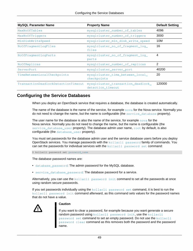
Configuring the Service Databases
49
MySQL Parameter Name Property Name Default Setting
MaxNoOfTables mysqlcluster_number_of_tables 4096
MaxNoOfTriggers mysqlcluster_number_of_triggers 3000
MinDiskWriteSpeed mysqlcluster_min_disk_write_speed 10M
NoOfFragmentLogFiles mysqlcluster_no_of_fragment_log_files
16
NoOfFragmentLogParts mysqlcluster_no_of_fragment_log_parts
4
NoOfReplicas mysqlcluster_number_of_replicas 2
ServerPort mysqlcluster_server_port 40200
TimeBetweenLocalCheckpoints mysqlcluster_time_between_local_checkpoints
20
TransactionDeadlockDetectionTimeout mysqlcluster_transaction_deadlock_detection_timeout
120000
Configuring the Service Databases
When you deploy an OpenStack service that requires a database, the database is created automatically.
The name of the database is the name of the service, for example nova for the Nova service. Normally youdo not need to change the name, but the name is configurable (the service_database property).
The user name for the database is also the name of the service, for example nova for theNova service. Normally you do not need to change the name, but the name is configurable (theservice_database_user property). The database admin user name, root by default, is alsoconfigurable (the database_user property).
You must set passwords for the database admin user and the service database users before you deployOpenStack services. You manage passwords with the kollacli password family of commands. Youcan set the passwords for individual services with the kollacli password set command:
$ kollacli password set password_name
The database password names are:
• database_password: The admin password for the MySQL database.
• service_database_password: The database password for a service.
Alternatively, you can use the kollacli password init command to set all the passwords at onceusing random secure passwords.
If you set passwords individually using the kollacli password set command, it is best to run thekollacli password init command afterward, as this command sets values for the password namesthat do not have a value.
Caution
If you want to clear a password, for example because you want generate a securerandom password using kollacli password init, use the kollaclipassword set command to set an empty password. Do not use the kollaclipassword clear command as this removes both the password and the passwordname.
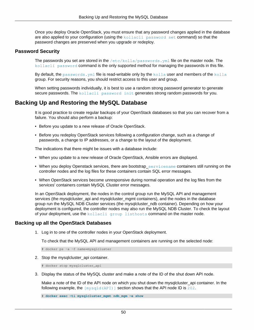
Backing Up and Restoring the MySQL Database
50
Once you deploy Oracle OpenStack, you must ensure that any password changes applied in the databaseare also applied to your configuration (using the kollacli password set command) so that thepassword changes are preserved when you upgrade or redeploy.
Password Security
The passwords you set are stored in the /etc/kolla/passwords.yml file on the master node. Thekollacli password command is the only supported method for managing the passwords in this file.
By default, the passwords.yml file is read-writable only by the kolla user and members of the kollagroup. For security reasons, you should restrict access to this user and group.
When setting passwords individually, it is best to use a random strong password generator to generatesecure passwords. The kollacli password init generates strong random passwords for you.
Backing Up and Restoring the MySQL Database
It is good practice to create regular backups of your OpenStack databases so that you can recover from afailure. You should also perform a backup:
• Before you update to a new release of Oracle OpenStack.
• Before you redeploy OpenStack services following a configuration change, such as a change ofpasswords, a change to IP addresses, or a change to the layout of the deployment.
The indications that there might be issues with a database include:
• When you update to a new release of Oracle OpenStack, Ansible errors are displayed.
• When you deploy Openstack services, there are bootstrap_servicename containers still running on thecontroller nodes and the log files for these containers contain SQL error messages.
• When OpenStack services become unresponsive during normal operation and the log files from theservices' containers contain MySQL Cluster error messages.
In an OpenStack deployment, the nodes in the control group run the MySQL API and managementservices (the mysqlcluster_api and mysqlcluster_mgmt containers), and the nodes in the databasegroup run the MySQL NDB Cluster services (the mysqlcluster_ndb container). Depending on how yourdeployment is configured, the controller nodes may also run the MySQL NDB Cluster. To check the layoutof your deployment, use the kollacli group listhosts command on the master node.
Backing up all the OpenStack Databases
1. Log in to one of the controller nodes in your OpenStack deployment.
To check that the MySQL API and management containers are running on the selected node:
# docker ps -a -f name=mysqlcluster
2. Stop the mysqlcluster_api container.
# docker stop mysqlcluster_api
3. Display the status of the MySQL cluster and make a note of the ID of the shut down API node.
Make a note of the ID of the API node on which you shut down the mysqlcluster_api container. In thefollowing example, the [mysqld(API)] section shows that the API node ID is 202.
# docker exec -ti mysqlcluster_mgmt ndb_mgm -e show
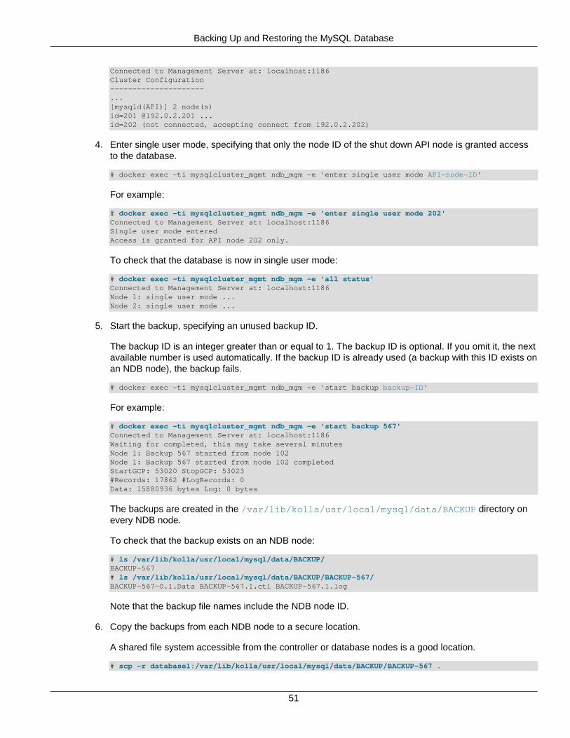
Backing Up and Restoring the MySQL Database
51
Connected to Management Server at: localhost:1186Cluster Configuration---------------------...[mysqld(API)] 2 node(s)id=201 @192.0.2.201 ...id=202 (not connected, accepting connect from 192.0.2.202)
4. Enter single user mode, specifying that only the node ID of the shut down API node is granted accessto the database.
# docker exec -ti mysqlcluster_mgmt ndb_mgm -e 'enter single user mode API-node-ID'
For example:
# docker exec -ti mysqlcluster_mgmt ndb_mgm -e 'enter single user mode 202' Connected to Management Server at: localhost:1186 Single user mode entered Access is granted for API node 202 only.
To check that the database is now in single user mode:
# docker exec -ti mysqlcluster_mgmt ndb_mgm -e 'all status'Connected to Management Server at: localhost:1186Node 1: single user mode ...Node 2: single user mode ...
5. Start the backup, specifying an unused backup ID.
The backup ID is an integer greater than or equal to 1. The backup ID is optional. If you omit it, the nextavailable number is used automatically. If the backup ID is already used (a backup with this ID exists onan NDB node), the backup fails.
# docker exec -ti mysqlcluster_mgmt ndb_mgm -e 'start backup backup-ID'
For example:
# docker exec -ti mysqlcluster_mgmt ndb_mgm -e 'start backup 567' Connected to Management Server at: localhost:1186Waiting for completed, this may take several minutesNode 1: Backup 567 started from node 102Node 1: Backup 567 started from node 102 completedStartGCP: 53020 StopGCP: 53023#Records: 17862 #LogRecords: 0Data: 15880936 bytes Log: 0 bytes
The backups are created in the /var/lib/kolla/usr/local/mysql/data/BACKUP directory onevery NDB node.
To check that the backup exists on an NDB node:
# ls /var/lib/kolla/usr/local/mysql/data/BACKUP/BACKUP-567# ls /var/lib/kolla/usr/local/mysql/data/BACKUP/BACKUP-567/BACKUP-567-0.1.Data BACKUP-567.1.ctl BACKUP-567.1.log
Note that the backup file names include the NDB node ID.
6. Copy the backups from each NDB node to a secure location.
A shared file system accessible from the controller or database nodes is a good location.
# scp -r database1:/var/lib/kolla/usr/local/mysql/data/BACKUP/BACKUP-567 .
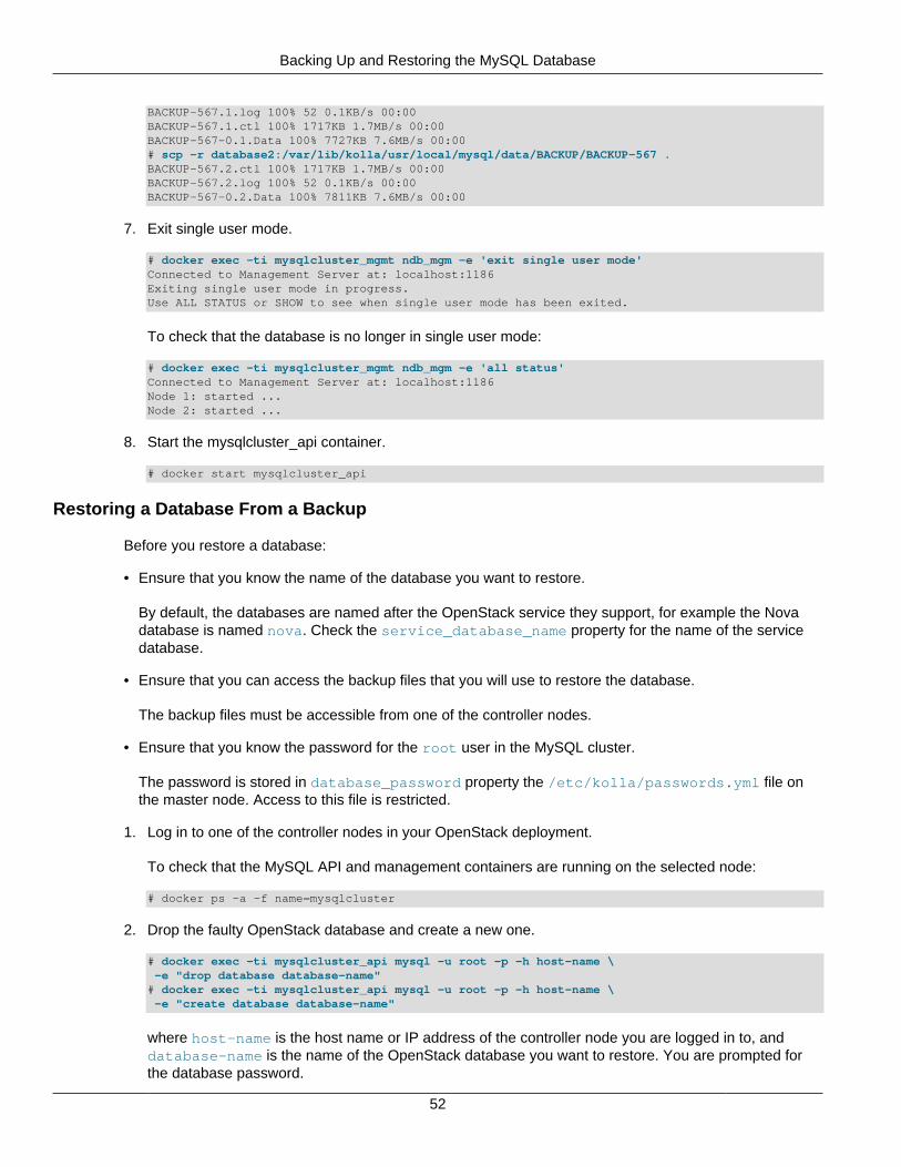
Backing Up and Restoring the MySQL Database
52
BACKUP-567.1.log 100% 52 0.1KB/s 00:00BACKUP-567.1.ctl 100% 1717KB 1.7MB/s 00:00BACKUP-567-0.1.Data 100% 7727KB 7.6MB/s 00:00 # scp -r database2:/var/lib/kolla/usr/local/mysql/data/BACKUP/BACKUP-567 .BACKUP-567.2.ctl 100% 1717KB 1.7MB/s 00:00BACKUP-567.2.log 100% 52 0.1KB/s 00:00BACKUP-567-0.2.Data 100% 7811KB 7.6MB/s 00:00
7. Exit single user mode.
# docker exec -ti mysqlcluster_mgmt ndb_mgm -e 'exit single user mode'Connected to Management Server at: localhost:1186Exiting single user mode in progress.Use ALL STATUS or SHOW to see when single user mode has been exited.
To check that the database is no longer in single user mode:
# docker exec -ti mysqlcluster_mgmt ndb_mgm -e 'all status'Connected to Management Server at: localhost:1186Node 1: started ...Node 2: started ...
8. Start the mysqlcluster_api container.
# docker start mysqlcluster_api
Restoring a Database From a Backup
Before you restore a database:
• Ensure that you know the name of the database you want to restore.
By default, the databases are named after the OpenStack service they support, for example the Novadatabase is named nova. Check the service_database_name property for the name of the servicedatabase.
• Ensure that you can access the backup files that you will use to restore the database.
The backup files must be accessible from one of the controller nodes.
• Ensure that you know the password for the root user in the MySQL cluster.
The password is stored in database_password property the /etc/kolla/passwords.yml file onthe master node. Access to this file is restricted.
1. Log in to one of the controller nodes in your OpenStack deployment.
To check that the MySQL API and management containers are running on the selected node:
# docker ps -a -f name=mysqlcluster
2. Drop the faulty OpenStack database and create a new one.
# docker exec -ti mysqlcluster_api mysql -u root -p -h host-name \ -e "drop database database-name"# docker exec -ti mysqlcluster_api mysql -u root -p -h host-name \ -e "create database database-name"
where host-name is the host name or IP address of the controller node you are logged in to, anddatabase-name is the name of the OpenStack database you want to restore. You are prompted forthe database password.
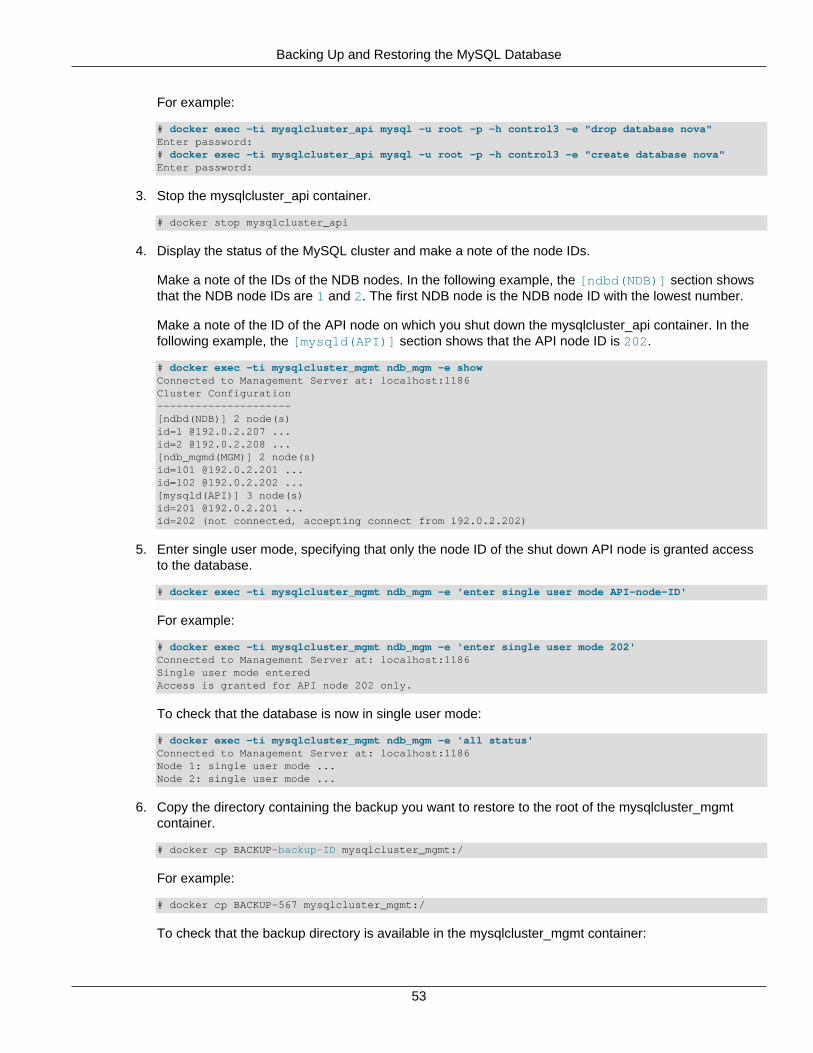
Backing Up and Restoring the MySQL Database
53
For example:
# docker exec -ti mysqlcluster_api mysql -u root -p -h control3 -e "drop database nova"Enter password:# docker exec -ti mysqlcluster_api mysql -u root -p -h control3 -e "create database nova"Enter password:
3. Stop the mysqlcluster_api container.
# docker stop mysqlcluster_api
4. Display the status of the MySQL cluster and make a note of the node IDs.
Make a note of the IDs of the NDB nodes. In the following example, the [ndbd(NDB)] section showsthat the NDB node IDs are 1 and 2. The first NDB node is the NDB node ID with the lowest number.
Make a note of the ID of the API node on which you shut down the mysqlcluster_api container. In thefollowing example, the [mysqld(API)] section shows that the API node ID is 202.
# docker exec -ti mysqlcluster_mgmt ndb_mgm -e showConnected to Management Server at: localhost:1186Cluster Configuration---------------------[ndbd(NDB)] 2 node(s)id=1 @192.0.2.207 ...id=2 @192.0.2.208 ...[ndb_mgmd(MGM)] 2 node(s)id=101 @192.0.2.201 ...id=102 @192.0.2.202 ...[mysqld(API)] 3 node(s)id=201 @192.0.2.201 ...id=202 (not connected, accepting connect from 192.0.2.202)
5. Enter single user mode, specifying that only the node ID of the shut down API node is granted accessto the database.
# docker exec -ti mysqlcluster_mgmt ndb_mgm -e 'enter single user mode API-node-ID'
For example:
# docker exec -ti mysqlcluster_mgmt ndb_mgm -e 'enter single user mode 202' Connected to Management Server at: localhost:1186 Single user mode entered Access is granted for API node 202 only.
To check that the database is now in single user mode:
# docker exec -ti mysqlcluster_mgmt ndb_mgm -e 'all status'Connected to Management Server at: localhost:1186Node 1: single user mode ...Node 2: single user mode ...
6. Copy the directory containing the backup you want to restore to the root of the mysqlcluster_mgmtcontainer.
# docker cp BACKUP-backup-ID mysqlcluster_mgmt:/
For example:
# docker cp BACKUP-567 mysqlcluster_mgmt:/
To check that the backup directory is available in the mysqlcluster_mgmt container:
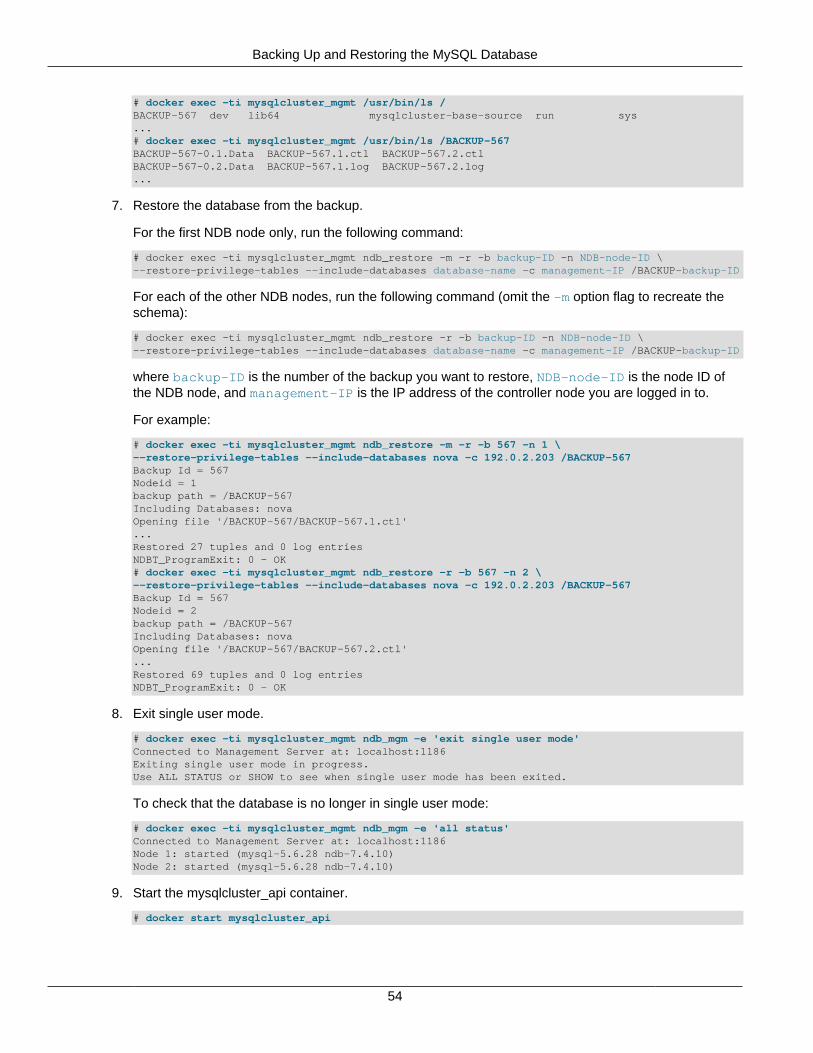
Backing Up and Restoring the MySQL Database
54
# docker exec -ti mysqlcluster_mgmt /usr/bin/ls /BACKUP-567 dev lib64 mysqlcluster-base-source run sys...# docker exec -ti mysqlcluster_mgmt /usr/bin/ls /BACKUP-567BACKUP-567-0.1.Data BACKUP-567.1.ctl BACKUP-567.2.ctlBACKUP-567-0.2.Data BACKUP-567.1.log BACKUP-567.2.log...
7. Restore the database from the backup.
For the first NDB node only, run the following command:
# docker exec -ti mysqlcluster_mgmt ndb_restore -m -r -b backup-ID -n NDB-node-ID \--restore-privilege-tables --include-databases database-name -c management-IP /BACKUP-backup-ID
For each of the other NDB nodes, run the following command (omit the -m option flag to recreate theschema):
# docker exec -ti mysqlcluster_mgmt ndb_restore -r -b backup-ID -n NDB-node-ID \--restore-privilege-tables --include-databases database-name -c management-IP /BACKUP-backup-ID
where backup-ID is the number of the backup you want to restore, NDB-node-ID is the node ID ofthe NDB node, and management-IP is the IP address of the controller node you are logged in to.
For example:
# docker exec -ti mysqlcluster_mgmt ndb_restore -m -r -b 567 -n 1 \--restore-privilege-tables --include-databases nova -c 192.0.2.203 /BACKUP-567Backup Id = 567Nodeid = 1backup path = /BACKUP-567Including Databases: novaOpening file '/BACKUP-567/BACKUP-567.1.ctl'...Restored 27 tuples and 0 log entriesNDBT_ProgramExit: 0 - OK# docker exec -ti mysqlcluster_mgmt ndb_restore -r -b 567 -n 2 \--restore-privilege-tables --include-databases nova -c 192.0.2.203 /BACKUP-567Backup Id = 567Nodeid = 2backup path = /BACKUP-567Including Databases: novaOpening file '/BACKUP-567/BACKUP-567.2.ctl'...Restored 69 tuples and 0 log entriesNDBT_ProgramExit: 0 - OK
8. Exit single user mode.
# docker exec -ti mysqlcluster_mgmt ndb_mgm -e 'exit single user mode'Connected to Management Server at: localhost:1186Exiting single user mode in progress.Use ALL STATUS or SHOW to see when single user mode has been exited.
To check that the database is no longer in single user mode:
# docker exec -ti mysqlcluster_mgmt ndb_mgm -e 'all status'Connected to Management Server at: localhost:1186Node 1: started (mysql-5.6.28 ndb-7.4.10)Node 2: started (mysql-5.6.28 ndb-7.4.10)
9. Start the mysqlcluster_api container.
# docker start mysqlcluster_api
Service Endpoint High Availability (Keepalived and HAProxy)
55
mysqlcluster_api
Service Endpoint High Availability (Keepalived and HAProxy)
Oracle OpenStack uses Keepalived and HAProxy to provide high availability and load balancing forthe OpenStack service endpoints. Keepalived and HAProxy are enabled by default (controlled by theenable_haproxy property), and they run on control nodes.
Keepalived manages the OpenStack internal and external virtual IP (VIP) addresses. When you deployOpenStack services, the kernel on the OpenStack node is modified to enable its network interfaces to bindto a non-local IP address (net.ipv4.ip_nonlocal_bind=1). This enables Keepalived to assign theVIP addresses to the network interfaces on one of the control nodes. If the control node that managesthe VIP addresses fails, Keepalived automatically assigns the VIP addresses to the network interfaces onanother control node (failover).
When the Docker service starts, the kernel on the OpenStack node is modified to enable IP forwarding(net.ipv4.ip_forward=1). HAProxy forwards requests on the VIP addresses to the OpenStack serviceendpoints on the internal management/API network. HAProxy also load-balances the requests between theOpenStack nodes that run the requested service.
See Configuring OpenStack Service Endpoints for more details about internal and external VIP addresses.
Keepalived has a virtual router ID, which is used to manage the virtual IP addresses. This ID mustbe unique to your OpenStack deployment. If you have multiple OpenStack deployments on the samemanagement/API network or an external instance of Keepalived on this network, you must configure aunique ID by setting the keepalived_virtual_router_id property. The default ID is 51. The ID is aninteger between 0 and 255.
Keepalived uses the Virtual Router Redundancy Protocol (VRRP) on the internal management/API networkto manage the VIP addresses. VRRP communication between the Keepalived instances is protectedwith password authentication. You configure the password (keepalived_password) with either thekollacli password set or the kollacli password init command. The password is stored in the/etc/kolla/passwords.yml file on the master node.
HAProxy comes with a web interface for monitoring the load balancer and the nodes that run HAProxy.The web interface is available at http://controller-node-IP-address:1984. The port is configurable(the haproxy_stats_port property). Access to the web interface is protected by HTTP BasicAuthentication (configured in the HAProxy configuration). The default user name is openstack(configurable with the haproxy_user property). You configure the password (haproxy_password) witheither the kollacli password set or the kollacli password init command. The password isstored in the /etc/kolla/passwords.yml file on the master node.
Example High Availability Configuration
Figure 3.5 shows an example of high availability for the Keystone public API endpoint. In this example,there are two control nodes (control1 and control2) with IP addresses 192.0.2.21 and 192.0.2.22 on theinternal management/API network, and the Keystone public API port is port 5000 (the default). The internaland external VIP configuration is as follows:
• kolla_external_vip_address: 203.0.113.10
• kolla_external_vip_interface: em3
• kolla_internal_vip_address: 192.0.2.100
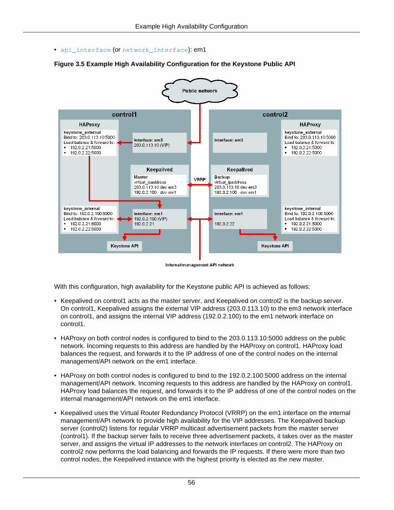
Example High Availability Configuration
56
• api_interface (or network_interface): em1
Figure 3.5 Example High Availability Configuration for the Keystone Public API
With this configuration, high availability for the Keystone public API is achieved as follows:
• Keepalived on control1 acts as the master server, and Keepalived on control2 is the backup server.On control1, Keepalived assigns the external VIP address (203.0.113.10) to the em3 network interfaceon control1, and assigns the internal VIP address (192.0.2.100) to the em1 network interface oncontrol1.
• HAProxy on both control nodes is configured to bind to the 203.0.113.10:5000 address on the publicnetwork. Incoming requests to this address are handled by the HAProxy on control1. HAProxy loadbalances the request, and forwards it to the IP address of one of the control nodes on the internalmanagement/API network on the em1 interface.
• HAProxy on both control nodes is configured to bind to the 192.0.2.100:5000 address on the internalmanagement/API network. Incoming requests to this address are handled by the HAProxy on control1.HAProxy load balances the request, and forwards it to the IP address of one of the control nodes on theinternal management/API network on the em1 interface.
• Keepalived uses the Virtual Router Redundancy Protocol (VRRP) on the em1 interface on the internalmanagement/API network to provide high availability for the VIP addresses. The Keepalived backupserver (control2) listens for regular VRRP multicast advertisement packets from the master server(control1). If the backup server fails to receive three advertisement packets, it takes over as the masterserver, and assigns the virtual IP addresses to the network interfaces on control2. The HAProxy oncontrol2 now performs the load balancing and forwards the IP requests. If there were more than twocontrol nodes, the Keepalived instance with the highest priority is elected as the new master.
Time Synchronization (Chrony)
57
Time Synchronization (Chrony)
Time synchronization is essential to avoid errors with OpenStack operations. Before deploying OpenStack,you should ensure that the time is synchronized on all nodes using the Network Time Protocol (NTP).There are two methods for achieving this:
• Enable the Chrony service in your OpenStack configuration (recommended).
• Enable NTP services manually on the nodes.
Only select one of these methods.
Enabling the Chrony Service
Rather than manually configuring NTP services on each OpenStack node, you can enable the Chronyservice so that it runs in a Docker container on the nodes. When the Chrony service is deployed, the NTPservers are configured automatically, as follows:
• All nodes are configured to use the control nodes as NTP servers. A control node does not use itself asan NTP server.
• Additional external NTP servers are configured, using the NTP servers defined by theexternal_ntp_servers property. By default, four NTP servers from pool.ntp.org are configured.
• On each OpenStack node, the Chrony service is configured to bind to the node's IP address on themanagement/API network (the api_interface property, which is set to the network_interfaceproperty by default). External NTP servers must be contactable on this network.
Currently the Chrony service is unable able to access NTP servers through a proxy server. If direct accessto NTP servers is not possible, you must configure NTP services on the hosts instead, see Manual NTPConfiguration below.
The Chrony service is disabled by default. If you enable it, you must disable NTP services on the nodes.
To enable the Chrony service:
$ kollacli property set enable_chrony yes
To configure external NTP servers:
$ kollacli property set external_ntp_servers \"['ntp1.example.com', 'ntp2.example.com', 'ntp3.example.com', 'ntp4.example.com']"
Manual NTP Configuration
If you want set up time synchronization manually, configure the controller nodes to synchronize the timefrom more accurate (lower stratum) NTP servers, and then configure the other nodes to synchronize thetime from the controller nodes.
The following configuration assumes that the firewall rules for your internal networks enable you to accesspublic or local NTP servers.
Oracle Linux Nodes
1. Install the chrony package.
# yum install chrony
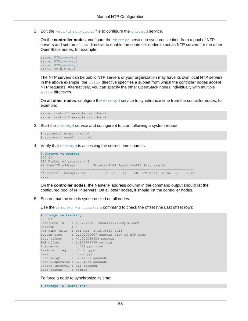
Manual NTP Configuration
58
2. Edit the /etc/chrony.conf file to configure the chronyd service.
On the controller nodes, configure the chronyd service to synchronize time from a pool of NTPservers and set the allow directive to enable the controller nodes to act as NTP servers for the otherOpenStack nodes, for example:
server NTP_server_1server NTP_server_2server NTP_server_3allow 192.0.2.0/24
The NTP servers can be public NTP servers or your organization may have its own local NTP servers.In the above example, the allow directive specifies a subnet from which the controller nodes acceptNTP requests. Alternatively, you can specify the other OpenStack nodes individually with multipleallow directives.
On all other nodes, configure the chronyd service to synchronize time from the controller nodes, forexample:
server control1.example.com iburstserver control2.example.com iburst
3. Start the chronyd service and configure it to start following a system reboot.
# systemctl start chronyd# systemctl enable chronyd
4. Verify that chronyd is accessing the correct time sources.
# chronyc -a sources200 OK210 Number of sources = 2MS Name/IP address Stratum Poll Reach LastRx Last sample===============================================================================^* control1.example.com 3 6 17 40 +9494ns[ +21us] +/- 29ms....
On the controller nodes, the Name/IP address column in the command output should list theconfigured pool of NTP servers. On all other nodes, it should list the controller nodes.
5. Ensure that the time is synchronized on all nodes.
Use the chronyc -a tracking command to check the offset (the Last offset row):
# chronyc -a tracking200 OKReference ID : 192.0.2.21 (control1.example.com)Stratum : 3Ref time (UTC) : Fri Mar 4 16:19:50 2016System time : 0.000000007 seconds slow of NTP timeLast offset : -0.000088924 secondsRMS offset : 2.834978580 secondsFrequency : 3.692 ppm slowResidual freq : -0.006 ppmSkew : 0.222 ppmRoot delay : 0.047369 secondsRoot dispersion : 0.004273 secondsUpdate interval : 2.1 secondsLeap status : Normal
To force a node to synchronize its time:
# chronyc -a 'burst 4/4'
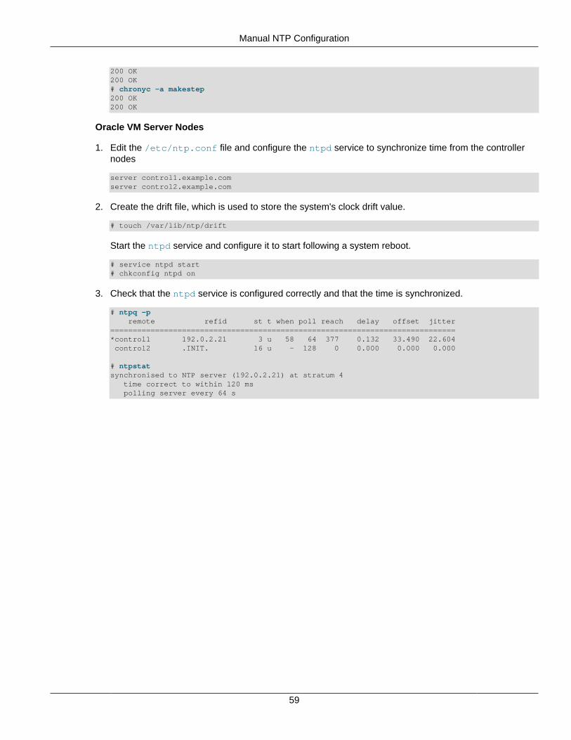
Manual NTP Configuration
59
200 OK200 OK# chronyc -a makestep200 OK200 OK
Oracle VM Server Nodes
1. Edit the /etc/ntp.conf file and configure the ntpd service to synchronize time from the controllernodes
server control1.example.comserver control2.example.com
2. Create the drift file, which is used to store the system's clock drift value.
# touch /var/lib/ntp/drift
Start the ntpd service and configure it to start following a system reboot.
# service ntpd start# chkconfig ntpd on
3. Check that the ntpd service is configured correctly and that the time is synchronized.
# ntpq -p remote refid st t when poll reach delay offset jitter=============================================================================*control1 192.0.2.21 3 u 58 64 377 0.132 33.490 22.604 control2 .INIT. 16 u - 128 0 0.000 0.000 0.000
# ntpstatsynchronised to NTP server (192.0.2.21) at stratum 4 time correct to within 120 ms polling server every 64 s

60
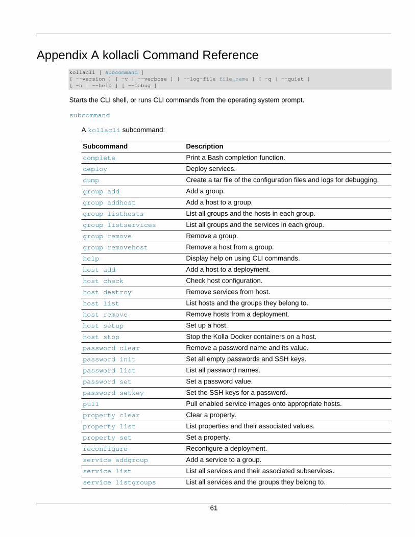
61
Appendix A kollacli Command Referencekollacli [ subcommand ][ --version ] [ -v | --verbose ] [ --log-file file_name ] [ -q | --quiet ][ -h | --help ] [ --debug ]
Starts the CLI shell, or runs CLI commands from the operating system prompt.
subcommand
A kollacli subcommand:
Subcommand Description
complete Print a Bash completion function.
deploy Deploy services.
dump Create a tar file of the configuration files and logs for debugging.
group add Add a group.
group addhost Add a host to a group.
group listhosts List all groups and the hosts in each group.
group listservices List all groups and the services in each group.
group remove Remove a group.
group removehost Remove a host from a group.
help Display help on using CLI commands.
host add Add a host to a deployment.
host check Check host configuration.
host destroy Remove services from host.
host list List hosts and the groups they belong to.
host remove Remove hosts from a deployment.
host setup Set up a host.
host stop Stop the Kolla Docker containers on a host.
password clear Remove a password name and its value.
password init Set all empty passwords and SSH keys.
password list List all password names.
password set Set a password value.
password setkey Set the SSH keys for a password.
pull Pull enabled service images onto appropriate hosts.
property clear Clear a property.
property list List properties and their associated values.
property set Set a property.
reconfigure Reconfigure a deployment.
service addgroup Add a service to a group.
service list List all services and their associated subservices.
service listgroups List all services and the groups they belong to.
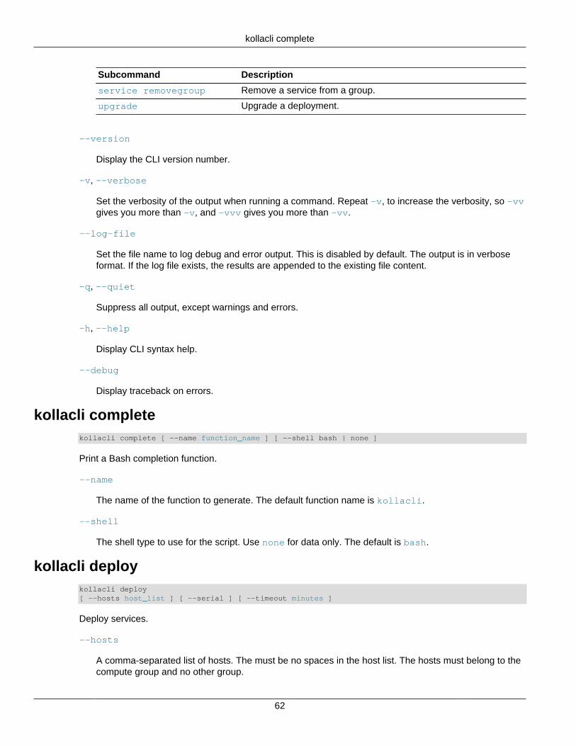
kollacli complete
62
Subcommand Description
service removegroup Remove a service from a group.
upgrade Upgrade a deployment.
--version
Display the CLI version number.
-v, --verbose
Set the verbosity of the output when running a command. Repeat -v, to increase the verbosity, so -vvgives you more than -v, and -vvv gives you more than -vv.
--log-file
Set the file name to log debug and error output. This is disabled by default. The output is in verboseformat. If the log file exists, the results are appended to the existing file content.
-q, --quiet
Suppress all output, except warnings and errors.
-h, --help
Display CLI syntax help.
--debug
Display traceback on errors.
kollacli completekollacli complete [ --name function_name ] [ --shell bash | none ]
Print a Bash completion function.
--name
The name of the function to generate. The default function name is kollacli.
--shell
The shell type to use for the script. Use none for data only. The default is bash.
kollacli deploykollacli deploy [ --hosts host_list ] [ --serial ] [ --timeout minutes ]
Deploy services.
--hosts
A comma-separated list of hosts. The must be no spaces in the host list. The hosts must belong to thecompute group and no other group.
kollacli dump
63
--serial
Deploy services serially (one host at a time).
--timeout
Timeout value in minutes. A deployment is stopped automatically if it takes longer than the timeoutvalue.
kollacli dumpkollacli dump
Create a tar file of the configuration files and logs for debugging.
kollacli group addkollacli group add group_name
Add a group.
group_name
The name of the group.
kollacli group addhostkollacli group addhost group_name host
Add a host to a group.
group_name
The name of the group.
host
The fully qualified domain name or IP address of the host.
kollacli group listhostskollacli group listhosts [ { -f | --format } csv | html | json | table | value | yaml ][ { -c | --column } column_name ] [ --max-width max_width ][ --quote all | minimal | none | nonnumeric ]
List all groups and the hosts in each group.
kollacli group listserviceskollacli group listservices [ { -f | --format } csv | html | json | table | value | yaml ][ { -c | --column } column_name ] [ --max-width max_width ][ --quote all | minimal | none | nonnumeric ]
List all groups and the services in each group.
kollacli group remove
64
kollacli group removekollacli group remove group_name
Remove a group.
group_name
The name of the group.
kollacli group removehostkollacli group removehost group_name host
Remove a host from a group.
group_name
The name of the group.
host
The fully qualified domain name or IP address of the host.
kollacli helpkollacli help [ command ]
Display help on using CLI commands.
command
Help on a specific kollacli command.
kollacli host addkollacli host add host
Add a host to a deployment.
host
The fully qualified domain name or IP address of the host.
kollacli host checkkollacli host check [ --predeploy ] { host | all }
Check host configuration.
--predeploy
Perform predeployment check. Only use this option if no services are deployed to the host.
host | all
The fully qualified domain name or IP address of the host, or all for all hosts.
kollacli host destroy
65
kollacli host destroykollacli host destroy [ --stop ] [ --includedata ] [--removeimages] { host | all }
Remove services from host.
--stop
Perform a graceful shutdown (docker stop) of the containers before removing them.
--includedata
Remove the OpenStack data.
--removeimages
Remove the OpenStack Docker images.
host | all
The fully qualified domain name or IP address of the host, or all for all hosts.
kollacli host listkollacli host list [ host ][ { -f | --format } csv | html | json | table | value | yaml ][ { -c | --column } column_name ] [ --max-width max_width ][ --quote all | minimal | none | nonnumeric ]
List hosts and the groups they belong to.
host
The fully qualified domain name or IP address of the host. If no host is provided, all hosts are listed.
kollacli host removekollacli host remove [ host | all ]
Remove hosts from a deployment.
host | all
The fully qualified domain name or IP address of the host, or all for all hosts.
kollacli host setupkollacli host setup { host | { -f | --file } file_name }
Set up a host.
host
The fully qualified domain name or IP address of the host.
-f --file
Absolute path of a YAML format file that contains the hosts to set up and the credentials to use.
kollacli host stop
66
kollacli host stopkollacli host stop [ host | all ]
Stop the Kolla Docker containers on a host.
host | all
The fully qualified domain name or IP address of the host, or all for all hosts.
kollacli password clearkollacli password clear password_name
Remove a password name and its value.
password_name
The name of the password.
kollacli password initkollacli password init password_name
Set all empty passwords and SSH keys.
kollacli password listkollacli password list
List all password names.
kollacli password setkollacli password set password_name
Set a password value.
password_name
The name of the password.
kollacli password setkeykollacli password setkey password_name private_key_path public_key_path
Set the SSH keys for a password.
password_name
The name of the password.
private_key_path
Path to the SSH private key file.
kollacli property clear
67
public_key_path
Path to the SSH public key file.
kollacli property clearkollacli property clear [ --groups group_list | --hosts host_list ] property_name
Clear a property.
property_name
The name of the property.
--groups
A comma-separated list of groups.
--hosts
A comma-separated list of hosts.
kollacli property listkollacli property list [ { -f | --format } csv | html | json | table | value | yaml ][ { -c | --column } column_name ] [ --max-width max_width ][ --quote all | minimal | none | nonnumeric ][ --all ] [ --long ][ --groups group_list | --hosts host_list ]
List properties and their associated values.
--all
List all properties and their values, regardless of their length.
--long
List properties, their current values, and their default values, if overridden by a global property.
--groups
A comma-separated list of groups.
--hosts
A comma-separated list of hosts.
kollacli property set
Set a property.
kollacli property set [ --groups group_list | --hosts host_list ] property_name value
property_name
The name of the property.
kollacli pull
68
value
The value to set for the property.
--groups
A comma-separated list of groups.
--hosts
A comma-separated list of hosts.
kollacli pullPull enabled service images onto appropriate hosts.
kollacli pull
kollacli reconfigureReconfigure a deployment.
kollacli reconfigure
kollacli service addgroupkollacli service addgroup service_name group_name
Add a service to a group.
service_name
The name of the service.
group_name
The name of the group.
kollacli service listkollacli service list [ { -f | --format } csv | html | json | table | value | yaml ][ { -c | --column } column_name ] [ --max-width max_width ][ --quote all | minimal | none | nonnumeric ]
List all services and their associated subservices.
kollacli service listgroupskollacli service listgroups [ { -f | --format } csv | html | json | table | value | yaml ][ { -c | --column } column_name ] [ --max-width max_width ][ --quote all | minimal | none | nonnumeric ]
List all services and the groups they belong to.
kollacli service removegroupkollacli service removegroup service_name group_name
kollacli upgrade
69
Remove a service from a group.
service_name
The name of the service.
group_name
The name of the group.
kollacli upgradekollacli upgrade [ --services service_list ]
Upgrade a deployment.
--services
A comma-separated list of services.

70