optimizing digital microscope brochure
DESCRIPTION
Optimizing Digital Microscope BrochureTRANSCRIPT
02
I N D E XDIGITAL MICROSCOPEGUIDE BOOK
1 MICROSCOPE STRUCTURE P4
2 LENS TYPES & LIGHT PRINCIPLES P6
3 ZOOM LENSES P8
4 ILLUMINATION METHODS & EFFECTS P10
5 HOW DIGITAL IMAGE PROCESSING WORKS P14
6 SIX ADDED VALUE FUNCTIONS - PART1 P16
7 DEPTH-OF-FIELD & DIGITAL FOCUSING TECHNIQUES
UTILIZING THE DIGITAL FOCUSING TECHNIQUE FOR DIGITAL MICROSCOPES
P18
P20
8 MAKING FULL USE OF THE 3D FUNCTION P22
9 SIX ADDED VALUE FUNCTIONS - PART2 P24
10 IMPROVING IMAGES OF DIGITAL MICROSCOPES-PART1
IMPROVING IMAGES OF DIGITAL MICROSCOPES-PART2
P26
P28
11 ABOUT NETWORKS
HOW TO UTILIZE A DIGITAL MICROSCOPE ON A NETWORK
HOW TO UTILIZE KEYENCE COMMUNICATION SOFTWARE
P30
P32
P34
03
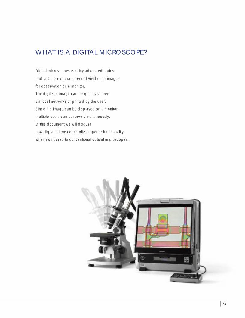
Digital microscopes employ advanced optics
and a CCD camera to record vivid color images
for observation on a monitor.
The digitized image can be quickly shared
via local networks or printed by the user.
Since the image can be displayed on a monitor,
multiple users can observe simultaneously.
In this document we will discuss
how digital microscopes offer superior functionality
when compared to conventional optical microscopes.
WHAT IS A DIGITAL MICROSCOPE?
DIGITAL MICROSCOPEGUIDE BOOK
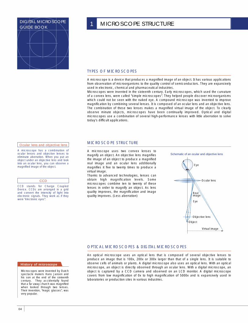
Schematic of an ocular and objective lens
TYPES OF MICROSCOPES
OPTICAL MICROSCOPES & DIGITAL MICROSCOPES
MICROSCOPE STRUCTURE
A microscope is a device that produces a magnified image of an object. It has various applications from observation of microorganisms to the quality control of semiconductors. They are expansively used in electronic, chemical and pharmaceutical industries.Microscopes were invented in the sixteenth century. Early microscopes, which used the curvature of a convex lens, were called "simple microscopes". They helped people discover microorganisms which could not be seen with the naked eye. A compound microscope was invented to improve magnification by combining several lenses. It is composed of an ocular lens and an objective lens. The combination of these two lenses makes a magnified virtual image of the object. To clearly observe minute objects, microscopes have been continually improved. Optical and digital microscopes use a combination of several high-performance lenses with little aberration to solve today's difficult applications.
A microscope uses two convex lenses to magnify an object. An objective lens magnifies the image of an object to produce a magnified real image and an ocular lens additionally magnifies it five to twenty times to produce a virtual image.Thanks to advanced technologies, lenses can obtain high magnification levels. Some microscopes combine ten to twenty of these lenses in order to magnify an object. As lens quality improves, the magnification and image quality improves. (Less aberration)
An optical microscope uses an optical lens that is composed of several objective lenses to produce an image that is 100x, 200x or 300x larger than that of a single lens. It is suitable to observe cells of animals or plants. A digital microscope also uses an optical lens. With an optical microscope, an object is directly observed through an ocular lens. With a digital microscope, an object is captured by a CCD camera and observed on an LCD monitor. A digital microscope covers from low magnification of 0x to high magnification of 5000x and is expansively used in laboratories or production sites in various industries.
Ocular lens
Objective lens
Virtual image
Eye
Real image
Object
Eye
History of microscope
A microscope has a combination of ocular lenses and objective lenses to eliminate aberration. When you put an object under an objective lens and look into an ocular lens, you can observe a magnified image of the object.
Microscopes were invented by Dutch spectacle makers Hans Jansen and his son at the end of the sixteenth century. They accidentally found that a far away church was magnified when looked through two lenses. Their invention, "magic glasses", was very popular.
Ocular lens and objective lens
CCD stands for Charge Coupled Device. CCDs are arranged in a grid and convert the intensity of light into electronic signals. They work as if they were "electronic eyes".
CCD
04
MICROSCOPE STRUCTURE1
05
LENS TECHNIQUES
Digital microscope
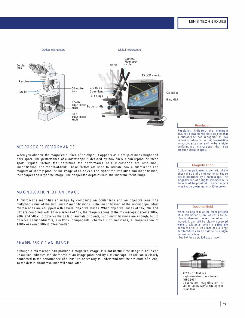
When an object is at the focal position of a microscope, the object can be clearly observed. When the object is moved, it can still be clearly observed within a tolerance, which is called the depth-of-field. A lens that has a large depth-of-field can be said to be a high- performance lens.*See P.6 for a detailed explanation.
KEYENCE featuresHigh-resolution zoom lenses [VH-Z500]Observation magnification is 500 to 5000x with a 10x optical zoom lens.
MICROSCOPE PERFORMANCE
MAGNIFICATION OF AN IMAGE
SHARPNESS OF AN IMAGE
When you observe the magnified surface of an object, it appears as a group of many bright and dark spots. The performance of a microscope is decided by how finely it can reproduce these spots. Typical factors that determine the performance of a microscope are 'resolution', 'magnification' and 'depth-of-field'. These factors are used to indicate how a microscope can magnify or sharply produce the image of an object. The higher the resolution and magnification, the sharper and larger the image. The deeper the depth-of-field, the wider the focus range.
A microscope magnifies an image by combining an ocular lens and an objective lens. The multiplied value of the two lenses' magnifications is the magnification of the microscope. Most microscopes are equipped with several objective lenses. When objective lenses of 10x, 20x and 50x are combined with an ocular lens of 10x, the magnifications of the microscope become 100x, 200x and 500x. To observe the cells of animals or plants, such magnifications are enough, but to observe semiconductors, electronic components, chemicals or medicines, a magnification of 1000x or even 5000x is often needed.
Although a microscope can produce a magnified image, it is not useful if the image is not clear. Resolution indicates the sharpness of an image produced by a microscope. Resolution is closely connected to the performance of a lens. It's necessary to understand first the structure of a lens, so the details about resolution will come later.
Resolution indicates the minimum distance between two close objects that a microscope can recognize as two separate objects. A high-resolution microscope can be said to be a high-performance microscope that can produce sharp images.
Resolution
Depth-of-field
Optical microscope
Ocular lens
ダミー�
Revolver
Coarse adjustment knob
Objective lens
Fine adjustment knob
Stage
Optical magnification is the ratio of the physical size of an object to its image that is produced by a microscope. The magnification of a digital microscope is the ratio of the physical size of an object to its image projected on a 15" monitor.
Magnification
Camera/Fiber optic cable
Stage handle
X-Y stage
Zoom lens
Camera
Z-axis dial
CD-R/RW
15 LCD monitor
Hard disk
DIGITAL MICROSCOPEGUIDE BOOK
06
LENS TYPES & LIGHT PRINCIPLES2
Characteristics of convex and concave lenses
Function
Gathers light to a point
Function of convex lenses
Function of concave lenses
Function
Spreads light
Schematic of light’s three primary colors
Schematic of incidence angle
Schematic of irregular reflection
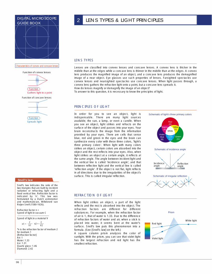
LENS TYPES
PRINCIPLES OF LIGHT
Lenses are classified into convex lenses and concave lenses. A convex lens is thicker in the middle than at the edges while a concave lens is thinner in the middle than at the edges. A convex lens produces the magnified image of an object, and a concave lens produces the demagnified image of a near object. Eye glasses use such properties of lenses. Farsighted spectacles use convex lenses and nearsighted spectacles use concave lenses. When light passes through, a convex lens gathers the refractive light onto a point, but a concave lens spreads it. How do lenses magnify or demagnify the image of an object? To answer to this question, it is necessary to know the principles of light.
In order for you to see an object, light is indispensable. There are many light sources available; the sun, a lamp, or even a candle. When you see an object, light strikes and refracts on the surface of the object and passes into your eyes. Your brain reconstructs the image from the information provided by your eyes. There are cells that sense blue, red and green in the eyes and the brain can synthesize every color with these three colors, 'light's three primary colors'. When light with many colors strikes an object, certain colors are absorbed into the object and the rest reflects into your eyes. Also, when light strikes an object at a certain angle, it reflects at the same angle. The angle between incident light and the vertical line is called 'incidence angle', and that between reflective light and the vertical line is called 'reflection angle'. If the object is not flat, light reflects in all directions due to the irregularities of the object's surface. This is called irregular reflection.
Prism
REFRACTION OF LIGHT
When light strikes an object, a part of the light reflects and the rest is absorbed into the object. The refraction factors are different for different substances. For example, when the refraction factor of air is 1, that of water is 1.33. Due to the difference of refraction factors of water and air, when a stick is placed into water, it seems bent at the water's surface. Snell's law puts this phenomenon into a formula. (See [Snell's law] on the left.)A square column prism analyzes the color of sunlight. With the prism, you can see that violet light has the largest refraction and red light has the smallest refraction.
White
Cyan(C)
Red(R)
Violet-blue(B)
Green(G)
Yellow(Y)
Magenta(M)
Incidence angle
Reflection angle
White lightRed light
Violet light
Snell's law indicates the ratio of the two triangles that are built by incident radiation or refracting light and a fixed vertical line. Refraction factor is indicated by 'n'. This law was formulated by a Dutch astronomer and mathematician, Willebrord van Roijen Snell (1580-1626).
Refraction factor n = Speed of light in vacuum C
Speed of light in a material V
*n is the refraction factor of medium 2 for medium 1[Refraction factor]Air: 1Water: 1.33Ice: 1.31Quartz glass: 1.46Diamond: 2.42
Snell's law
CV1
CV2
n1 = n2 =
�
07
LENS TECHNIQUES
Schematic of chromatic aberration
NON-GLASS LENSES
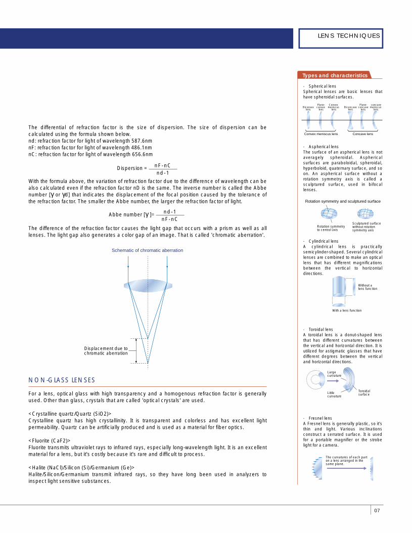
The differential of refraction factor is the size of dispersion. The size of dispersion can be calculated using the formula shown below.nd: refraction factor for light of wavelength 587.6nmnF: refraction factor for light of wavelength 486.1nmnC: refraction factor for light of wavelength 656.6nm
With the formula above, the variation of refraction factor due to the difference of wavelength can be also calculated even if the refraction factor nD is the same. The inverse number is called the Abbe number [γ or γd] that indicates the displacement of the focal position caused by the tolerance of the refraction factor. The smaller the Abbe number, the larger the refraction factor of light.
The difference of the refraction factor causes the light gap that occurs with a prism as well as all lenses. The light gap also generates a color gap of an image. That is called 'chromatic aberration'.
For a lens, optical glass with high transparency and a homogenous refraction factor is generally used. Other than glass, crystals that are called 'optical crystals' are used.
<Crystalline quartz/Quartz (SiO2)>Crystalline quartz has high crystallinity. It is transparent and colorless and has excellent light permeability. Quartz can be artificially produced and is used as a material for fiber optics.
<Fluorite (CaF2)>Fluorite transmits ultraviolet rays to infrared rays, especially long-wavelength light. It is an excellent material for a lens, but it's costly because it's rare and difficult to process.
<Halite (NaCl)/Silicon (Si)/Germanium (Ge)>Halite/Silicon/Germanium transmit infrared rays, so they have long been used in analyzers to inspect light sensitive substances.
Displacement due to chromatic aberration
Types and characteristics
● Spherical lensSpherical lenses are basic lenses that have spheroidal surfaces.
● Aspherical lensThe surface of an aspherical lens is not averagely spheroidal. Aspherical surfaces are paraboloidal, spheroidal, hyperboloid, quaternary surface, and so on. An aspherical surface without a rotation symmetry axis is called a sculptured surface, used in bifocal lenses.
● Cylindrical lensA cylindrical lens is practically semicylinder-shaped. Several cylindrical lenses are combined to make an optical lens that has different magnifications between the vertical to horizontal directions.
● Toroidal lensA toroidal lens is a donut-shaped lens that has different curvatures between the vertical and horizontal direction. It is utilized for astigmatic glasses that have different degrees between the vertical and horizontal directions.
● Fresnel lensA Fresnel lens is generally plastic, so it's thin and light. Various inclinations construct a serrated surface. It is used for a portable magnifier or the strobe light for a camera.
Rotation symmetryto central axis
Sculptured surface without rotation symmetry axis
Convex meniscus lens
Biconvexlens
Concave lens
Plane-convex
lens
Convex meniscus
lensBiconcave
lens
Plane-concave
lens
concavemeniscus
lens
Rotation symmetry and sculptured surface
With a lens function
Without a lens function
The curvatures of each part on a lens arranged in the same plane.
Large curvature
Little curvature
Toroidal surface
nF-nCnd-1
Dispersion =
nd-1nF-nC
Abbe number [γ ]=
DIGITAL MICROSCOPEGUIDE BOOK
08
ZOOM LENSES3
There are several types of aberration. Aberration causes the phenomena described below.
wThe center part of a screen is focused, but the periphery is defocused.
wStraight lines seems bent. (It occurs more often at the periphery than at the center)
wSmall spots leave comet-like traces.
w Color drift
Aberration Characteristics
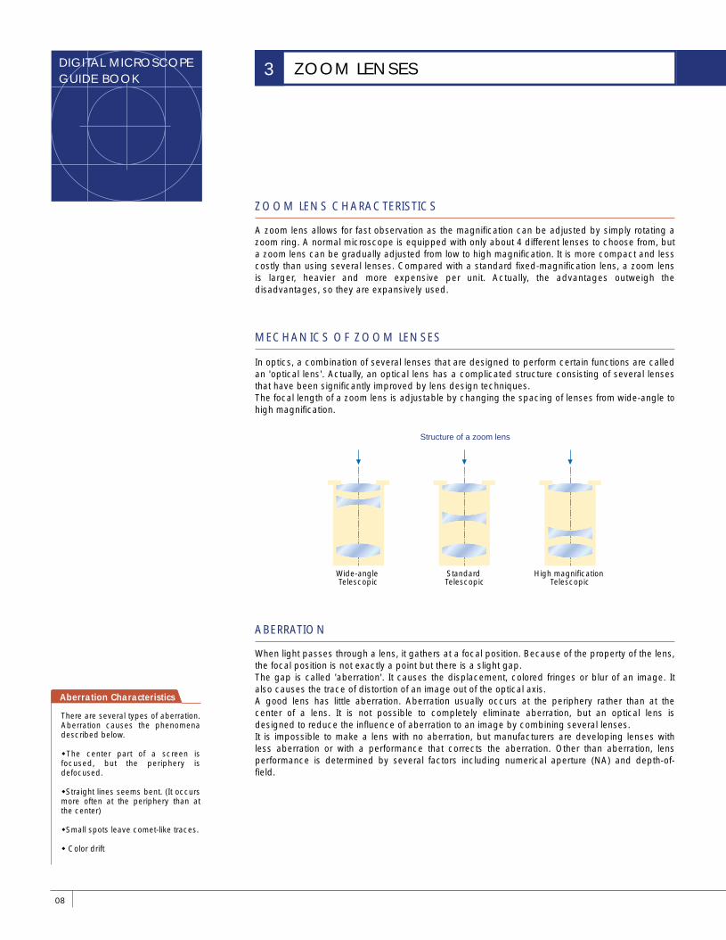
MECHANICS OF ZOOM LENSES
In optics, a combination of several lenses that are designed to perform certain functions are called an 'optical lens'. Actually, an optical lens has a complicated structure consisting of several lenses that have been significantly improved by lens design techniques.The focal length of a zoom lens is adjustable by changing the spacing of lenses from wide-angle to high magnification.
ABERRATION
When light passes through a lens, it gathers at a focal position. Because of the property of the lens, the focal position is not exactly a point but there is a slight gap.The gap is called 'aberration'. It causes the displacement, colored fringes or blur of an image. It also causes the trace of distortion of an image out of the optical axis.A good lens has little aberration. Aberration usually occurs at the periphery rather than at the center of a lens. It is not possible to completely eliminate aberration, but an optical lens is designed to reduce the influence of aberration to an image by combining several lenses.It is impossible to make a lens with no aberration, but manufacturers are developing lenses with less aberration or with a performance that corrects the aberration. Other than aberration, lens performance is determined by several factors including numerical aperture (NA) and depth-of-field.
Structure of a zoom lens
Wide-angle Telescopic
Standard Telescopic
High magnification Telescopic
ZOOM LENS CHARACTERISTICS
A zoom lens allows for fast observation as the magnification can be adjusted by simply rotating a zoom ring. A normal microscope is equipped with only about 4 different lenses to choose from, but a zoom lens can be gradually adjusted from low to high magnification. It is more compact and less costly than using several lenses. Compared with a standard fixed-magnification lens, a zoom lens is larger, heavier and more expensive per unit. Actually, the advantages outweigh the disadvantages, so they are expansively used.
09
LENS TECHNIQUES
DEPTH-OF-FIELD
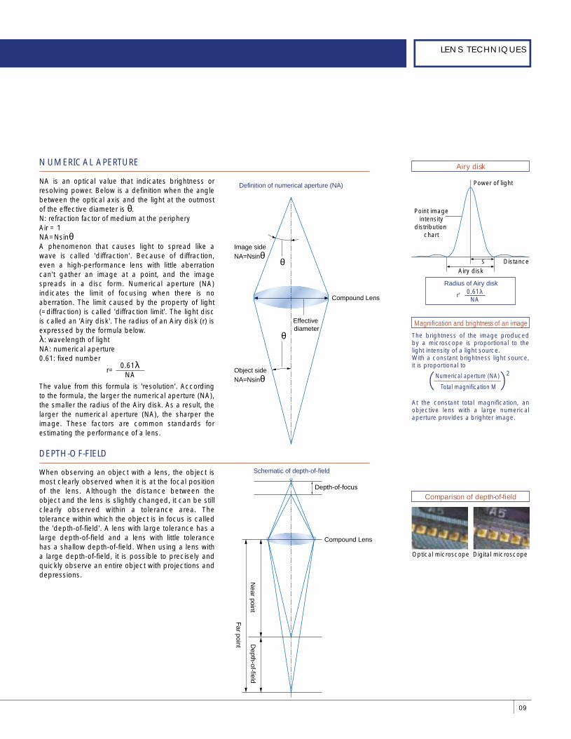
NUMERICAL APERTURE
NA is an optical value that indicates brightness or resolving power. Below is a definition when the angle between the optical axis and the light at the outmost of the effective diameter is θ.N: refraction factor of medium at the peripheryAir = 1NA=NsinθA phenomenon that causes light to spread like a wave is called 'diffraction'. Because of diffraction, even a high-performance lens with little aberration can't gather an image at a point, and the image spreads in a disc form. Numerical aperture (NA) indicates the limit of focusing when there is no aberration. The limit caused by the property of light (=diffraction) is called 'diffraction limit'. The light disc is called an 'Airy disk'. The radius of an Airy disk (r) is expressed by the formula below.λ: wavelength of lightNA: numerical aperture0.61: fixed number
The value from this formula is 'resolution'. According to the formula, the larger the numerical aperture (NA), the smaller the radius of the Airy disk. As a result, the larger the numerical aperture (NA), the sharper the image. These factors are common standards for estimating the performance of a lens.
When observing an object with a lens, the object is most clearly observed when it is at the focal position of the lens. Although the distance between the object and the lens is slightly changed, it can be still clearly observed within a tolerance area. The tolerance within which the object is in focus is called the 'depth-of-field'. A lens with large tolerance has a large depth-of-field and a lens with little tolerance has a shallow depth-of-field. When using a lens with a large depth-of-field, it is possible to precisely and quickly observe an entire object with projections and depressions.
Definition of numerical aperture (NA)
Schematic of depth-of-field
Object sideNA=Nsinθ
Image sideNA=Nsinθ
θ
θ
Effective diameter
Depth-of-focus
Near point
Depth-of-field
Far point
Airy disk
Comparison of depth-of-field
Airy disk
Radius of Airy disk
r=
Distance
Power of light
Point image intensity
distribution chart
r
0.61λNA
Optical microscope Digital microscope
The brightness of the image produced by a microscope is proportional to the light intensity of a light source.With a constant brightness light source, it is proportional to
At the constant total magnification, an objective lens with a large numerical aperture provides a brighter image.
Magnification and brightness of an image
Numerical aperture (NA) 2
Total magnification M
0.61λNA
r=
Compound Lens
Compound Lens
DIGITAL MICROSCOPEGUIDE BOOK
10
ILLUMINATION METHODS & EFFECTS4
Lens light source
ILLUMINATION METHODS & MICROSCOPE TYPES
ILLUMINATION BEST-SUITED TO THE OBJECT & PURPOSE
DIGITAL MICROSCOPES WITH BUILT-IN ILLUMINATION
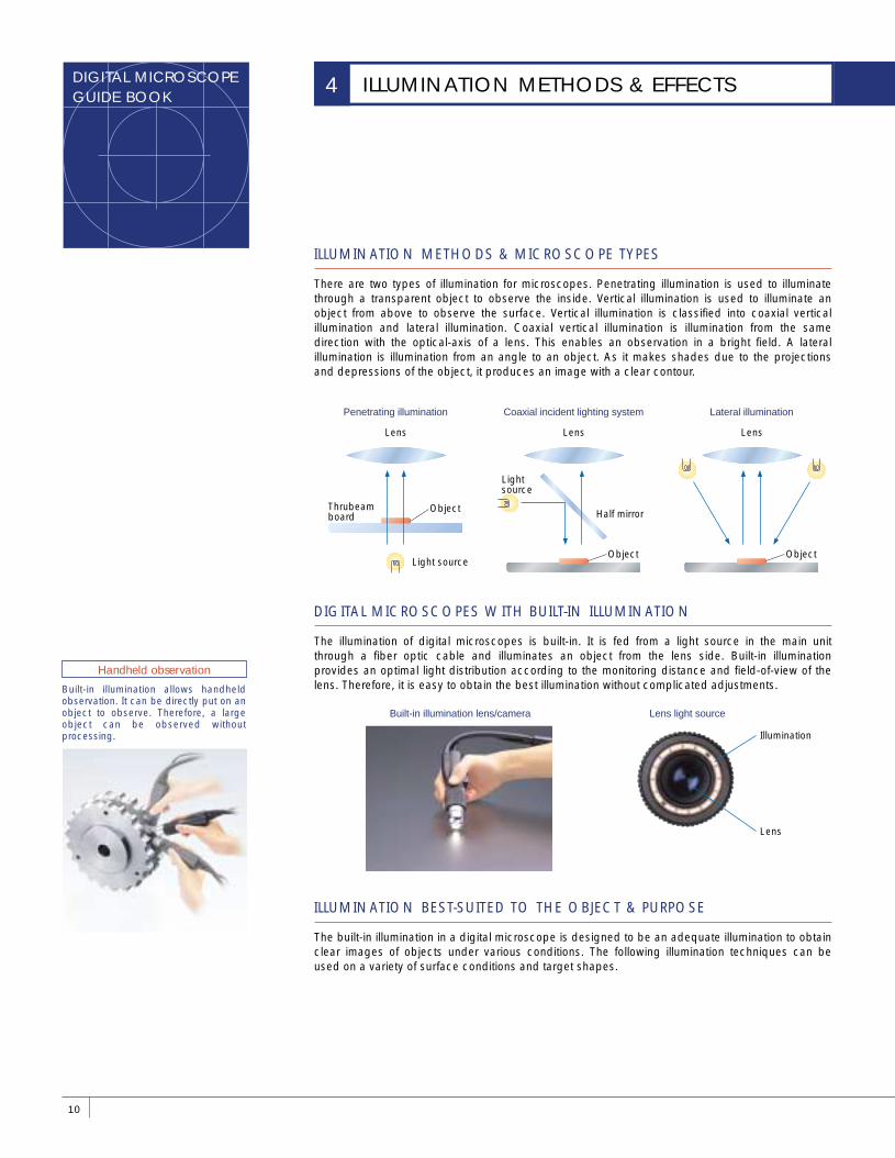
There are two types of illumination for microscopes. Penetrating illumination is used to illuminate through a transparent object to observe the inside. Vertical illumination is used to illuminate an object from above to observe the surface. Vertical illumination is classified into coaxial vertical illumination and lateral illumination. Coaxial vertical illumination is illumination from the same direction with the optical-axis of a lens. This enables an observation in a bright field. A lateral illumination is illumination from an angle to an object. As it makes shades due to the projections and depressions of the object, it produces an image with a clear contour.
The illumination of digital microscopes is built-in. It is fed from a light source in the main unit through a fiber optic cable and illuminates an object from the lens side. Built-in illumination provides an optimal light distribution according to the monitoring distance and field-of-view of the lens. Therefore, it is easy to obtain the best illumination without complicated adjustments.
The built-in illumination in a digital microscope is designed to be an adequate illumination to obtain clear images of objects under various conditions. The following illumination techniques can be used on a variety of surface conditions and target shapes.
Lens
Penetrating illumination
Lens
Coaxial incident lighting system
Lens
Object
Half mirror
Lateral illumination
Light source
Light source
ObjectThrubeam board
Object
Built-in illumination lens/camera
Illumination
Lens
Built-in illumination allows handheld observation. It can be directly put on an object to observe. Therefore, a large object can be observed without processing.
Handheld observation
11
LENS TECHNIQUES
OPTICAL ILLUMINATION TECHNIQUE -COAXIAL VERTICAL ILLUMINATION-
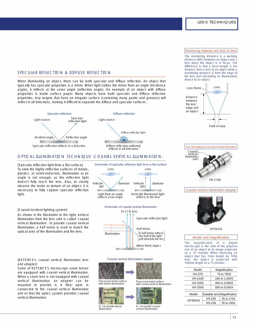
SPECULAR REFLECTION & DIFFUSE REFLECTION
When illuminating an object, there can be both specular and diffuse reflection. An object that typically has specular properties is a mirror. When light strikes the mirror from an angle (incidence angle), it reflects at the same angle (reflection angle). An example of an object with diffuse properties is matte surface paper. Many objects have both specular and diffuse reflective properties. Any targets that have an irregular surface (containing many peaks and grooves) will reflect in all directions, making it difficult to separate the diffuse and specular surfaces.
Specular reflection
[Specular reflection light from a flat surface]To view the highly reflective surfaces of metals, plastics, or semiconductors, illumination at an angle is not enough, as the reflective light doesn't fully reach the lens. Also, to clearly observe the luster or texture of an object, it is necessary to fully capture specular reflection light.
[Coaxial incident lighting system]
As shown in the illustration to the right, vertical illumination from the lens side is called 'coaxial vertical illumination'. To provide coaxial vertical illumination, a half mirror is used to match the optical axes of the illumination and the lens.
Schematic of specular reflection light from a flat surface
Schematic of coaxial vertical illumination
Reflective light
Lens
Light from an angle reflects at an angle
Illumination Reflective light
Illumination
Lens
Vertically illuminated light reflects to the lens
Diffuse reflection light
Light source
Diffuse reflection uniformly reflects in all directions.
To CCD lens
Specular reflection light
Half mirror
Mirror finish object
A half mirror reflects the half of the light and transmits the rest.
Illumination
[KEYENCE's coaxial vertical illumination lens and adapter]Some of KEYENCE's microscope zoom lenses are equipped with coaxial vertical illumination. When a zoom lens is not equipped with coaxial vertical illumination, an adapter can be mounted to provide it. A fiber optic is connected to the coaxial vertical illumination unit so that the optics system provides coaxial vertical illumination.
Processed metal surface with lateral illumination
Processed metal surface with coaxial vertical illumination
Coaxial vertical illumination adapter
IC circuit with lateral illumination
IC circuit with coaxial vertical illumination
Light source Specular reflection light
Specular reflection reflects in a direction.
Incident angle Reflection angle
Diffuse reflection
Model
VH-Z75
VH-Z100
VH-Z450
VH-Z500
Magnification
75 to 750X
100 to 1,000X
450 to 3,000X
500 to 5,000X
Magnification
25 to 175X
35 to 245X
Suitable lens
VH-Z25
VH-Z35
Model
OP35416
Zoom lens equipped with coaxial vertical illumination
Coaxial vertical illumination adapter
Model and magnification
Coaxialvertical
illuminationunit
Monitoring distance and field of view
LensLens frame
Field of view
Distance between the lens' edge and an object
OP35416
VH-Z100
The monitoring distance is a working distance (WD) between an object and a lens when the object is in focus. The difference is that a focal length is the distance from a lens to an object while a monitoring distance is from the edge of the lens part (including an illumination) device to an object.
The magnification of a digital microscope is the ratio of the physical size of an object to its image projected on a 15" monitor. When observing an object that has 1mm length by 100x lens, the object is projected with 100mm length on a 15 monitor.
DIGITAL MICROSCOPEGUIDE BOOK
12
ILLUMINATION METHODS & EFFECTS 4
VH-K25
Full illumination/Partial illumination
Diffuse illumination adapter
Adjustable illumination adapter
Suitable lens/MagnificationNameModel
Model and name
Only one-fourth of the illuminations at the tip turn on. The projectionsand depressions areenhanced
All illuminations at the tip turn on.
Partial illuminationFull illumination
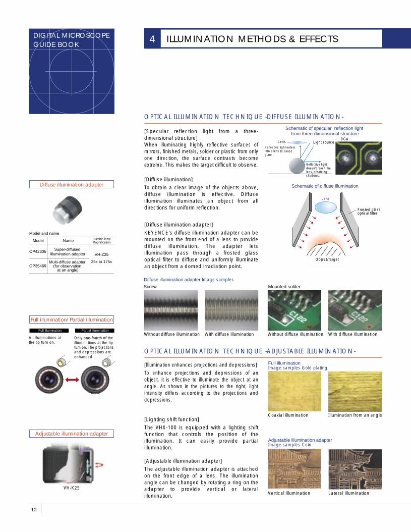
OPTICAL ILLUMINATION TECHNIQUE -DIFFUSE ILLUMINATION-
[Specular reflection light from a three-dimensional structure]When illuminating highly reflective surfaces of mirrors, finished metals, solder or plastic from only one direction, the surface contrasts become extreme. This makes the target difficult to observe.
[Diffuse illumination]
To obtain a clear image of the objects above, diffuse illumination is effective. Diffuse illumination illuminates an object from all directions for uniform reflection.
[Diffuse illumination adapter]
KEYENCE's diffuse illumination adapter can be mounted on the front end of a lens to provide diffuse illumination. The adapter lets illumination pass through a frosted glass optical filter to diffuse and uniformly illuminate an object from a domed irradiation point.
[Illumination enhances projections and depressions]
To enhance projections and depressions of an object, it is effective to illuminate the object at an angle. As shown in the pictures to the right, light intensity differs according to the projections and depressions.
[Lighting shift function]
The VHX-100 is equipped with a lighting shift function that controls the position of the illumination. It can easily provide partial illumination.
[Adjustable illumination adapter]
The adjustable illumination adapter is attached on the front edge of a lens. The illumination angle can be changed by rotating a ring on the adapter to provide vertical or lateral illumination.
OPTICAL ILLUMINATION TECHNIQUE -ADJUSTABLE ILLUMINATION-
Schematic of specular reflection light from three-dimensional structure
Object/Target
Lens
Frosted glass optical filter
Schematic of diffuse illumination
Diffuse illumination adapter Image samples
Light source
Reflective light doesn't reach the lens, createing shadows.
Reflective light enters into a lens to cause glare
Lens● BGA
Without diffuse illumination With diffuse illumination Without diffuse illumination With diffuse illumination
Mounted solder
Coaxial illumination Illumination from an angle
Full illumination Image samples Gold plating
Vertical illumination Lateral illumination
Adjustable illumination adapter Image samples Coin
Screw
Multi-diffuse adapter (for observation
at an angle)
Super-diffused illumination adapter
OP35469
OP42305VH-Z25
25x to 175x
13
LENS TECHNIQUES
OPTICAL ILLUMINATION TECHNIQUE -POLARIZED ILLUMINATION-
OPTICAL ILLUMINATION TECHNIQUE -PENETRATING ILLUMINATION-
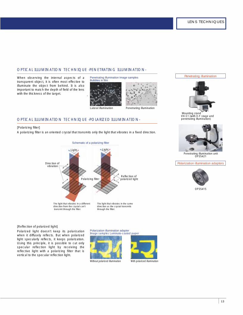
When observing the internal aspects of a transparent object, it is often most effective to illuminate the object from behind. It is also important to match the depth of field of the lens with the thickness of the target.
Penetrating illumination Image samplesBubbles in film
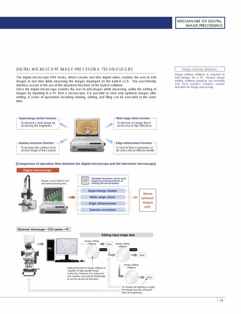
Polarization illumination adapter Image samples Laminate-coated paper
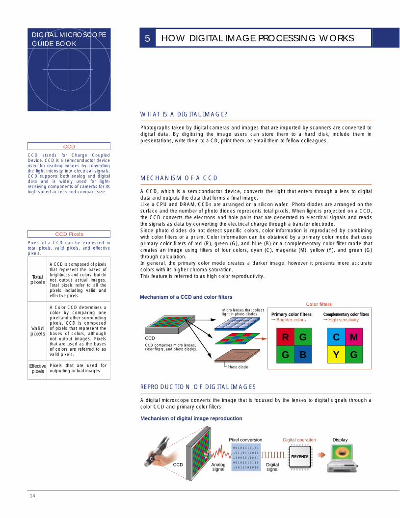
[Polarizing filter]
A polarizing filter is an oriented crystal that transmits only the light that vibrates in a fixed direction.
[Reflection of polarized light]
Polarized light doesn't keep its polarization when it diffusely reflects. But when polarized light specularly reflects, it keeps polarization. Using this principle, it is possible to cut only specular reflection light by receiving the reflective light with a polarizing filter that is vertical to the specular reflection light.
Schematic of a polarizing filter
Lateral illumination Penetrating illumination
Without polarized illumination With polarized illumination
Polarizing filterReflection of polarized light
Direction of vibration
Light Light
Penetrating illumination
Polarization illumination adapters
Mounting standVH-S1 (with X-Y stage and penetrating illumination)
Penetrating illumination unitOP35421
OP35415
The light that vibrates in a different direction from the crystal can't transmit through the filter.
The light that vibrates in the same direction as the crystal transmits through the filter.
DIGITAL MICROSCOPEGUIDE BOOK
REPRODUCTION OF DIGITAL IMAGES
MECHANISM OF A CCD
WHAT IS A DIGITAL IMAGE?
Photographs taken by digital cameras and images that are imported by scanners are converted to digital data. By digitizing the image users can store them to a hard disk, include them in presentations, write them to a CD, print them, or email them to fellow colleagues.
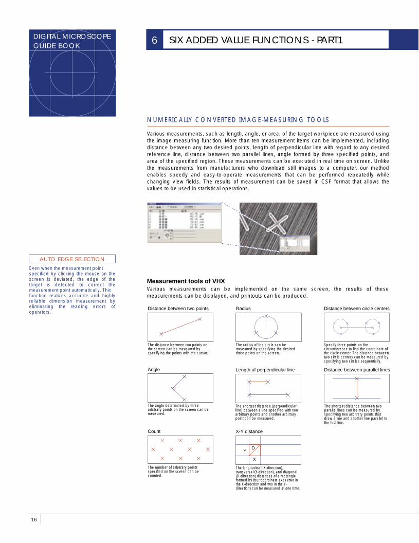
A CCD, which is a semiconductor device, converts the light that enters through a lens to digital data and outputs the data that forms a final image. Like a CPU and DRAM, CCDs are arranged on a silicon wafer. Photo diodes are arranged on the surface and the number of photo diodes represents total pixels. When light is projected on a CCD, the CCD converts the electrons and hole pairs that are generated to electrical signals and reads the signals as data by converting the electrical charge through a transfer electrode. Since photo diodes do not detect specific colors, color information is reproduced by combining with color filters or a prism. Color information can be obtained by a primary color mode that uses primary color filters of red (R), green (G), and blue (B) or a complementary color filter mode that creates an image using filters of four colors, cyan (C), magenta (M), yellow (Y), and green (G) through calculation. In general, the primary color mode creates a darker image, however it presents more accurate colors with its higher chroma saturation.This feature is referred to as high color reproductivity.
A digital microscope converts the image that is focused by the lenses to digital signals through a color CCD and primary color filters.
14
HOW DIGITAL IMAGE PROCESSING WORKS5
Color filters
CCD comprises micro lenses, color filters, and photo diodes.
CCD
Micro lenses that collect light in photo diodes
Mechanism of a CCD and color filters
R G
G B
C M
Y GPhoto diode
Primary color filters Brighter colors
Complementary color filters High sensitivity
Mechanism of digital image reproduction
Digital operation
CCD Analog signal
Digital signal
Pixel conversion Display
0010111010110110110010110010110010010101011010011101010
CCD stands for Charge Coupled Device. CCD is a semiconductor device used for reading images by converting the light intensity into electrical signals. CCD supports both analog and digital data and is widely used for light-receiving components of cameras for its high-speed access and compact size.
CCD
Pixels of a CCD can be expressed in total pixels, valid pixels, and effective pixels.
CCD Pixels
A CCD is composed of pixels that represent the bases of brightness and colors, but do not output actual images. Total pixels refer to all the pixels including valid and effective pixels.
Total pixels
A Color CCD determines a color by comparing one pixel and other surrounding pixels. CCD is composed of pixels that represent the bases of colors, although not output images. Pixels that are used as the bases of colors are referred to as valid pixels.
Valid pixels
Pixels that are used for outputting actual images
Effective pixels
15
MECHANISM OF DIGITAL IMAGE PROCESSING
Image editing software is required to edit images on a PC. Various image editing software products are available and each product contains various functions for image processing.
Image editing software DIGITAL MICROSCOPE IMAGE PROCESSING TECHNOLOGIES
The digital microscope VHX Series, which creates real time digital video, enables the user to edit images in real time while observing the images displayed on the built-in LCD. The user-friendly interface assists in the use of the abundant functions of the built-in software. Since the digital microscope enables the user to edit images while observing, unlike the editing of images by inputting to a PC from a microscope, it is possible to store only optimum images after editing. A series of operations including viewing, editing, and filing can be executed at the same time.
Supercharge shutter function
To observe a dark image by increasing the brightness
Gamma correction function
To increase the contrast of an unclear image of low contrast
Wide range check function
To observe an image that is unclear due to high reflectance
Edge enhancement function
To check for flaws or unevenness on the surface that are difficult to identify
Correct
To change the lighting or angle, the image must be reloaded from the beginning.
Digital microscope
Supercharge shutter
Wide range check
Edge enhancement
Gamma correction
[Comparison of operation flow between the digital microscope and the electronic microscope]
Images can be edited in real time while observing them.
Abundant functions can be used simply by pressing buttons or clicking the mouse button
ORIGINALGRAPHICENGINE
Electronic microscope + CCD camera + PC
Store
Store
Image editing software Image editing
software
Store
Editing input image data
Image editing software High-performance image software is
capable of high-quality image correction, however, it is expensive and requires specialized knowledge to use its advanced functions.
Storesoptimum images
only
Correct
DIGITAL MICROSCOPEGUIDE BOOK
NUMERICALLY CONVERTED IMAGE-MEASURING TOOLS
Various measurements, such as length, angle, or area, of the target workpiece are measured using the image measuring function. More than ten measurement items can be implemented, including distance between any two desired points, length of perpendicular line with regard to any desired reference line, distance between two parallel lines, angle formed by three specified points, and area of the specified region. These measurements can be executed in real time on screen. Unlike the measurements from manufacturers who download still images to a computer, our method enables speedy and easy-to-operate measurements that can be performed repeatedly while changing view fields. The results of measurement can be saved in CSF format that allows the values to be used in statistical operations.
16
SIX ADDED VALUE FUNCTIONS - PART16
Distance between parallel lines
Distance between two points
Count
Length of perpendicular line
X-Y distance
X
YD
Radius Distance between circle centers
Various measurements can be implemented on the same screen, the results of these measurements can be displayed, and printouts can be produced.
The distance between two points on the screen can be measured by specifying the points with the cursor.
The radius of the circle can be measured by specifying the desired three points on the screen.
Specify three points on the circumference to find the coordinate of the circle center. The distance between two circle centers can be measured by specifying two circles sequentially.
The shortest distance (perpendicular line) between a line specified with two arbitrary points and another arbitrary point can be measured.
The shortest distance between two parallel lines can be measured by specifying two arbitrary points that draw a line and another line parallel to the first line.
The longitudinal (X-direction), transversal (Y-direction), and diagonal (D-direction) distances of a rectangle formed by four coordinate axes (two in the X-direction and two in the Y-direction) can be measured at one time.
Angle
The angle determined by three arbitrary points on the screen can be measured.
The number of arbitrary points specified on the screen can be counted.
Measurement tools of VHX
Even when the measurement pointspecified by clicking the mouse on the screen is deviated, the edge of the target is detected to correct the measurement point automatically. Thisfunction realizes accurate and highly reliable dimension measurement by eliminating the reading errors of operators.
AUTO EDGE SELECTION
17
MECHANISM OF DIGITAL IMAGE PROCESSING
This shiftware provides more advanced analysis features than the auto measurement. For example, it can conduct more detailed analysis of a Feret's diameter or a center coordinate as well as separating overlapping circular particles and conducting the measurement.
Particle analyzer
A special glass scale simplifies automatic calibration. You can also issue a calibration certificate to meet the demand of traceability.
Reference scale
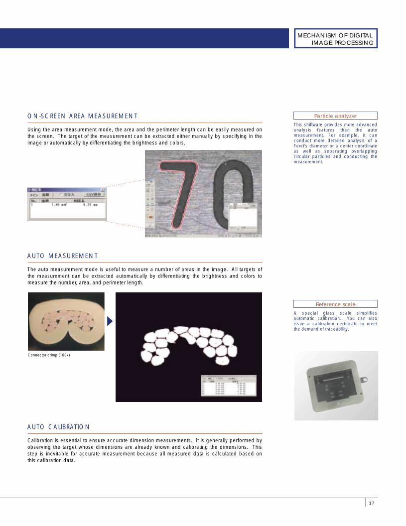
ON-SCREEN AREA MEASUREMENT
Using the area measurement mode, the area and the perimeter length can be easily measured on the screen. The target of the measurement can be extracted either manually by specifying in the image or automatically by differentiating the brightness and colors.
AUTO MEASUREMENT
The auto measurement mode is useful to measure a number of areas in the image. All targets of the measurement can be extracted automatically by differentiating the brightness and colors to measure the number, area, and perimeter length.
AUTO CALIBRATION
Calibration is essential to ensure accurate dimension measurements. It is generally performed by observing the target whose dimensions are already known and calibrating the dimensions. This step is inevitable for accurate measurement because all measured data is calculated based on this calibration data.
Connector crimp (100x)
DIGITAL MICROSCOPEGUIDE BOOK
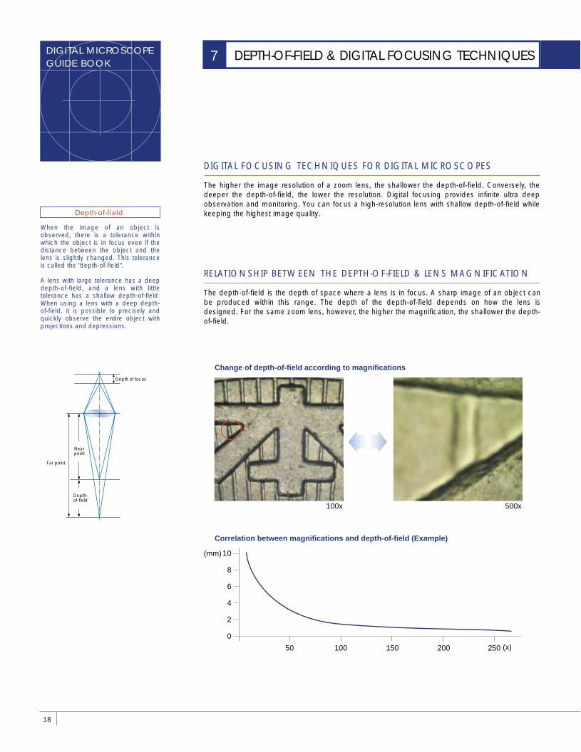
RELATIONSHIP BETWEEN THE DEPTH-OF-FIELD & LENS MAGNIFICATION
DIGITAL FOCUSING TECHNIQUES FOR DIGITAL MICROSCOPES
The higher the image resolution of a zoom lens, the shallower the depth-of-field. Conversely, the deeper the depth-of-field, the lower the resolution. Digital focusing provides infinite ultra deep observation and monitoring. You can focus a high-resolution lens with shallow depth-of-field while keeping the highest image quality.
The depth-of-field is the depth of space where a lens is in focus. A sharp image of an object can be produced within this range. The depth of the depth-of-field depends on how the lens is designed. For the same zoom lens, however, the higher the magnification, the shallower the depth-of-field.
18
DEPTH-OF-FIELD & DIGITAL FOCUSING TECHNIQUES7
Depth-of-field
When the image of an object is observed, there is a tolerance within which the object is in focus even if the distance between the object and the lens is slightly changed. This tolerance is called the "depth-of-field".
A lens with large tolerance has a deep depth-of-field, and a lens with little tolerance has a shallow depth-of-field. When using a lens with a deep depth-of-field, it is possible to precisely and quickly observe the entire object with projections and depressions.
Depth of focus
Correlation between magnifications and depth-of-field (Example)
Change of depth-of-field according to magnifications
100x 500x
10
8
6
4
2
0
50 100 150 200 250
Far point
Near point
Depth-of-field
(x)
(mm)
19
DIGITAL FOCUSING IMAGE
CCD stands for Charge Coupled Device. The CCD is a semiconductor device (media) for image capturing. It converts the intensity of light to electrical signals and stores them. It features support of both analog and digital. The CCD has been downsized, so it is often used as the light-receiving part of a camera.
CCD
Pixel refers to the number of picture elements in an area per unit when resolutions of a digital camera and display, etc. are represented.
Pixel
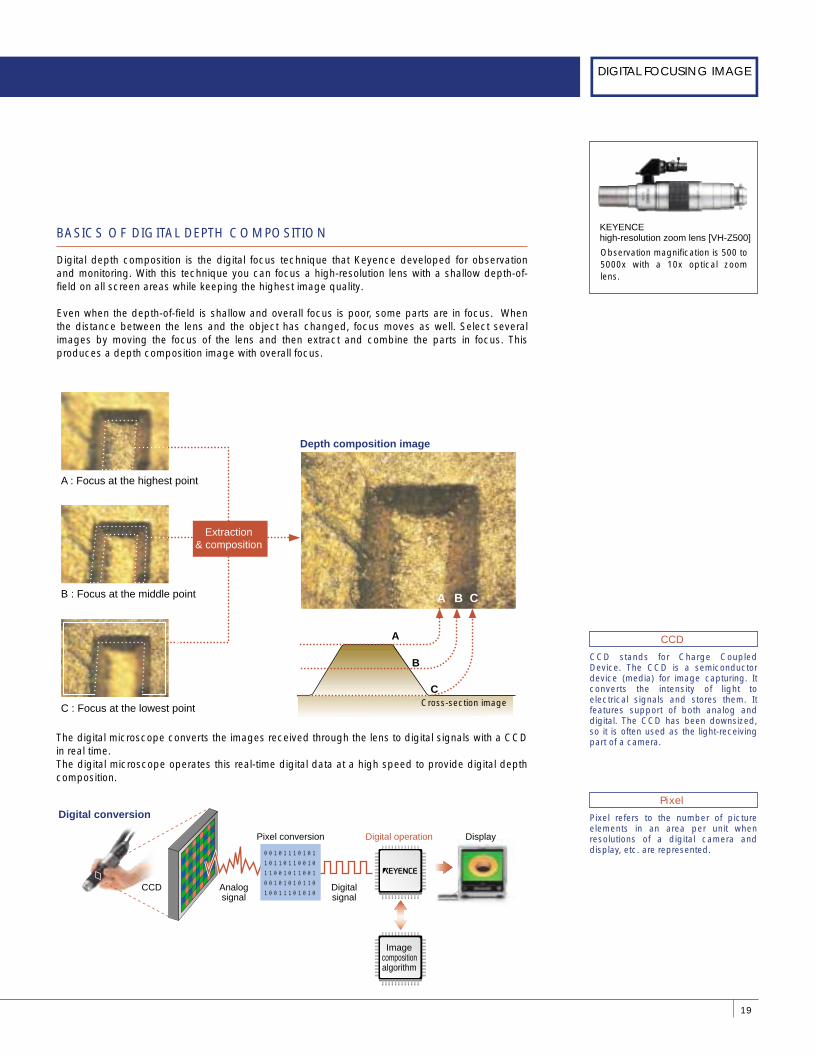
Depth composition image
A
A B C
B
CCross-section image
Extraction & composition
A : Focus at the highest point
B : Focus at the middle point
C : Focus at the lowest point
BASICS OF DIGITAL DEPTH COMPOSITION
Digital depth composition is the digital focus technique that Keyence developed for observation and monitoring. With this technique you can focus a high-resolution lens with a shallow depth-of-field on all screen areas while keeping the highest image quality.
Even when the depth-of-field is shallow and overall focus is poor, some parts are in focus. When the distance between the lens and the object has changed, focus moves as well. Select several images by moving the focus of the lens and then extract and combine the parts in focus. This produces a depth composition image with overall focus.
Digital conversion
Digital operation
CCD Analog signal
Digital signal
Pixel conversion Display
0010111010110110110010110010110010010101011010011101010
Image composition algorithm
The digital microscope converts the images received through the lens to digital signals with a CCD in real time. The digital microscope operates this real-time digital data at a high speed to provide digital depth composition.
Observation magnification is 500 to 5000x with a 10x optical zoom lens.
KEYENCE high-resolution zoom lens [VH-Z500]
DIGITAL MICROSCOPEGUIDE BOOK
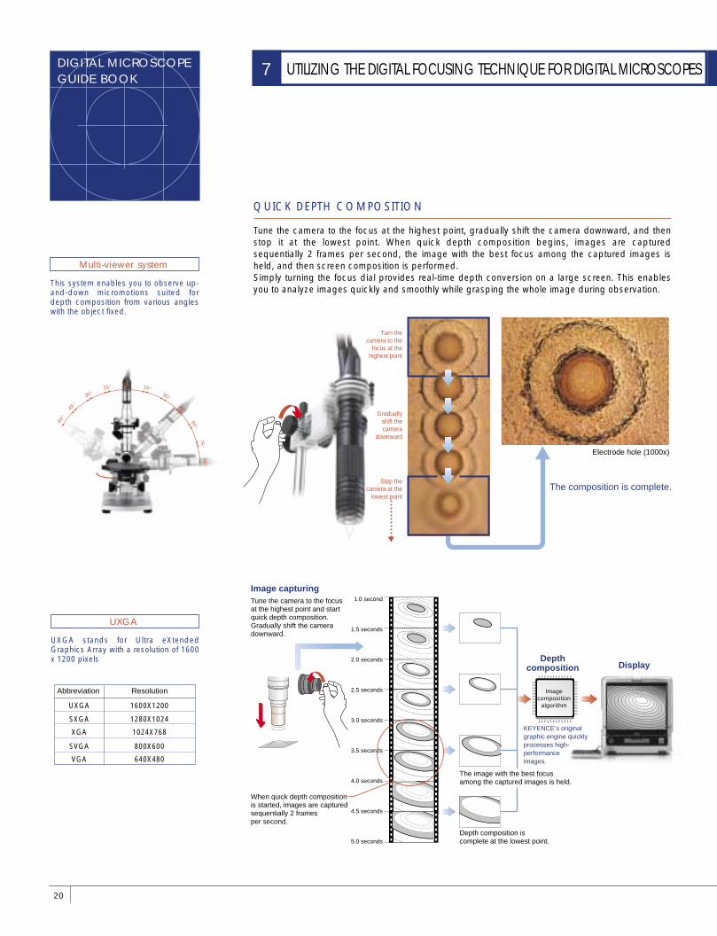
QUICK DEPTH COMPOSITION
Tune the camera to the focus at the highest point, gradually shift the camera downward, and then stop it at the lowest point. When quick depth composition begins, images are captured sequentially 2 frames per second, the image with the best focus among the captured images is held, and then screen composition is performed. Simply turning the focus dial provides real-time depth conversion on a large screen. This enables you to analyze images quickly and smoothly while grasping the whole image during observation.
20
UTILIZING THE DIGITAL FOCUSING TECHNIQUE FOR DIGITAL MICROSCOPES7
Multi-viewer system
This system enables you to observe up-and-down micromotions suited for depth composition from various angles with the object fixed.
UXGA
UXGA stands for Ultra eXtended Graphics Array with a resolution of 1600 x 1200 pixels
60°
45°
30° 15° 0° 15°
30°
45° 60°
75°90°
UXGA 1600X1200
SXGA 1280X1024
XGA 1024X768
SVGA 800X600
VGA 640X480
Abbreviation Resolution
Electrode hole (1000x)
The composition is complete.
Image composition
algorithm
Depth composition Display
Tune the camera to the focus at the highest point and start quick depth composition.Gradually shift the camera downward.
1.0 second
1.5 seconds
2.0 seconds
2.5 seconds
3.0 seconds
3.5 seconds
4.0 seconds
4.5 seconds
5.0 seconds
KEYENCE’s original graphic engine quickly processes high-performance images.
Image capturing
When quick depth composition is started, images are captured sequentially 2 frames per second.
The image with the best focus among the captured images is held.
Depth composition is complete at the lowest point.
�
Turn thecamera to the
focus at thehighest point
Graduallyshift thecamera
downward
Stop thecamera at the
lowest point
21
DIGITAL FOCUSING IMAGE
Algorithm is a procedure that effectively handles programs.
Algorithm
The Linear stage enables you to obtain equally spaced images while moving the lens through operation with the main unit. It also provides automation of high-quality depth composition.
Linear stage
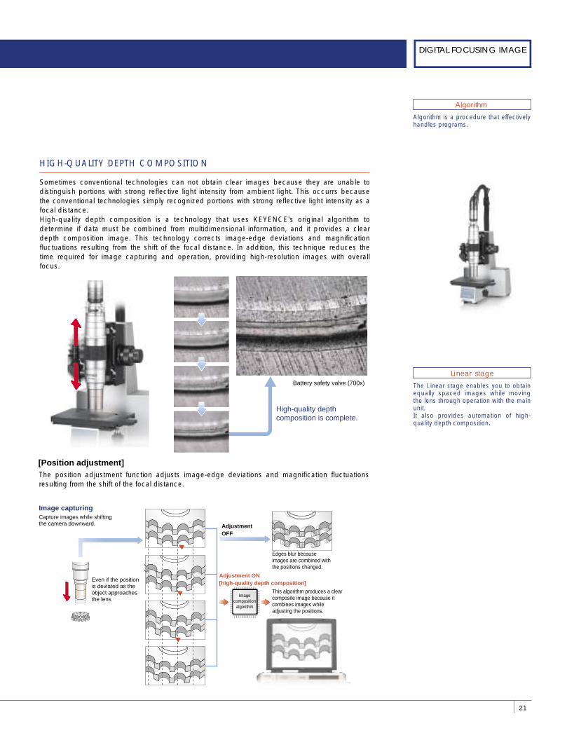
HIGH-QUALITY DEPTH COMPOSITION
Sometimes conventional technologies can not obtain clear images because they are unable to distinguish portions with strong reflective light intensity from ambient light. This occurrs because the conventional technologies simply recognized portions with strong reflective light intensity as a focal distance. High-quality depth composition is a technology that uses KEYENCE's original algorithm to determine if data must be combined from multidimensional information, and it provides a clear depth composition image. This technology corrects image-edge deviations and magnification fluctuations resulting from the shift of the focal distance. In addition, this technique reduces the time required for image capturing and operation, providing high-resolution images with overall focus.
The position adjustment function adjusts image-edge deviations and magnification fluctuations resulting from the shift of the focal distance.
Battery safety valve (700x)
High-quality depth composition is complete.
Edges blur because images are combined with the positions changed.
This algorithm produces a clear composite image because it combines images while adjusting the positions.
Adjustment OFF
Adjustment ON [high-quality depth composition]
Capture images while shifting the camera downward.
Image capturing
Image composition
algorithm
[Position adjustment]
Even if the position is deviated as the object approaches the lens
DIGITAL MICROSCOPEGUIDE BOOK
DIGITAL MICROSCOPE 3D DISPLAY FUNCTION
It was very difficult for conventional optical microscopes to observe an oblique or rotating tiny target in high-magnification observation. The 3D display function for digital microscopes has enabled this. This function enables you to observe an enlarged target while freely changing the orientation as if the target were placed on your palm.
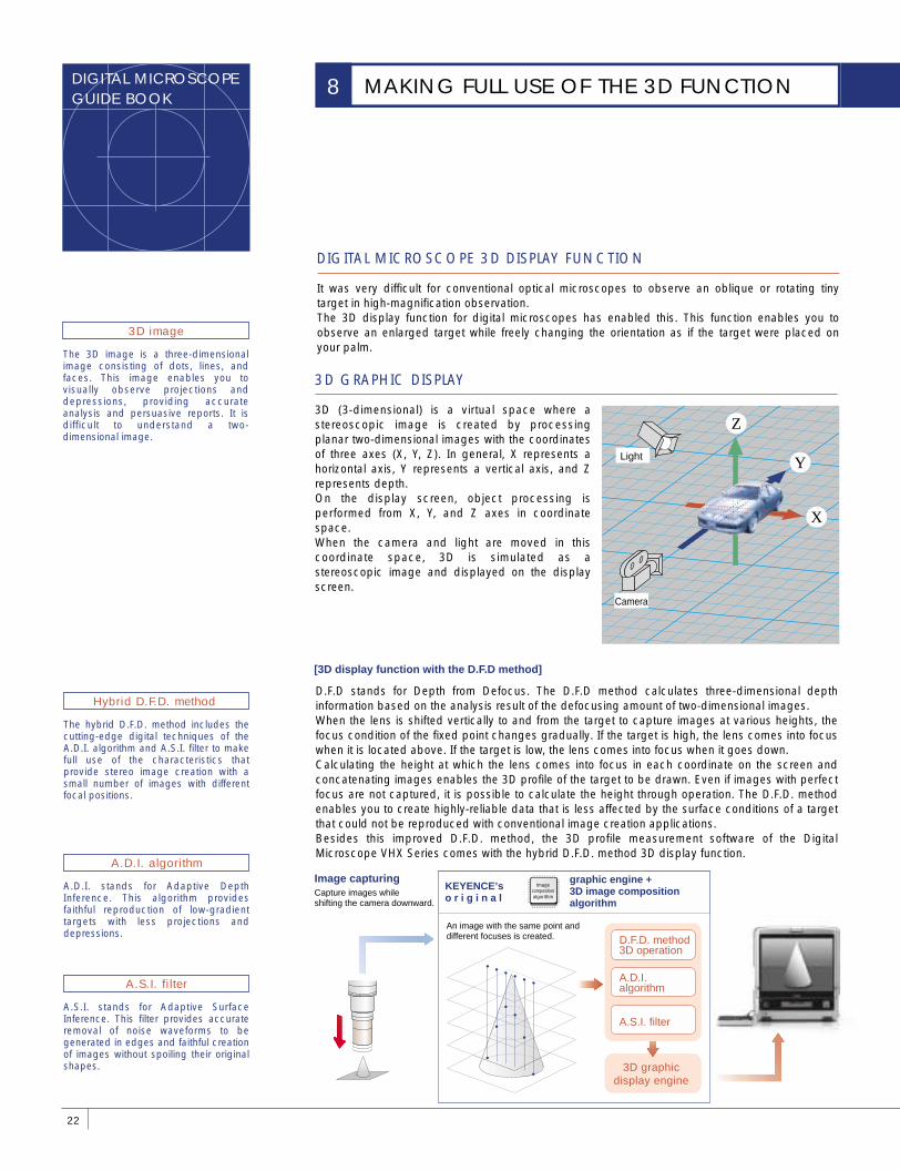
D.F.D stands for Depth from Defocus. The D.F.D method calculates three-dimensional depth information based on the analysis result of the defocusing amount of two-dimensional images. When the lens is shifted vertically to and from the target to capture images at various heights, the focus condition of the fixed point changes gradually. If the target is high, the lens comes into focus when it is located above. If the target is low, the lens comes into focus when it goes down. Calculating the height at which the lens comes into focus in each coordinate on the screen and concatenating images enables the 3D profile of the target to be drawn. Even if images with perfect focus are not captured, it is possible to calculate the height through operation. The D.F.D. method enables you to create highly-reliable data that is less affected by the surface conditions of a target that could not be reproduced with conventional image creation applications. Besides this improved D.F.D. method, the 3D profile measurement software of the Digital Microscope VHX Series comes with the hybrid D.F.D. method 3D display function.
3D GRAPHIC DISPLAY
3D (3-dimensional) is a virtual space where a stereoscopic image is created by processing planar two-dimensional images with the coordinates of three axes (X, Y, Z). In general, X represents a horizontal axis, Y represents a vertical axis, and Z represents depth. On the display screen, object processing is performed from X, Y, and Z axes in coordinate space. When the camera and light are moved in this coordinate space, 3D is simulated as a stereoscopic image and displayed on the display screen.
22
MAKING FULL USE OF THE 3D FUNCTION8
3D image
The 3D image is a three-dimensional image consisting of dots, lines, and faces. This image enables you to visually observe projections and depressions, providing accurate analysis and persuasive reports. It is difficult to understand a two-dimensional image.
Hybrid D.F.D. method
The hybrid D.F.D. method includes the cutting-edge digital techniques of the A.D.I. algorithm and A.S.I. filter to make full use of the characteristics that provide stereo image creation with a small number of images with different focal positions.
A.D.I. algorithm
A.D.I. stands for Adaptive Depth Inference. This algorithm provides faithful reproduction of low-gradient targets with less projections and depressions.
A.S.I. filter
A.S.I. stands for Adaptive Surface Inference. This filter provides accurate removal of noise waveforms to be generated in edges and faithful creation of images without spoiling their original shapes.
Camera
Light
X
Z
Y
KEYENCE’s o r i g i n a l
An image with the same point and different focuses is created.
Capture images while shifting the camera downward.
Image capturingImage
composition algorithm
3D graphic display engine
D.F.D. method 3D operation
A.D.I.algorithm
A.S.I. filter
[3D display function with the D.F.D method]
graphic engine + 3D image composition algorithm
23
DIGITAL FOCUSING IMAGE
3D DISPLAY APPLICATION TECHNIQUES
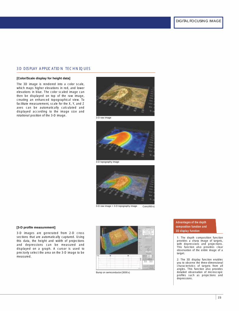
The 3D image is rendered into a color scale, which maps higher elevations in red, and lower elevations in blue. The color scaled image can then be displayed on top of the raw image, creating an enhanced topographical view. To facilitate measurement, scale for the X, Y, and Z axes can be automatically calculated and displayed according to the image size and rotational position of the 3-D image.
3-D images are generated from 2-D cross sections that are automatically captured. Using this data, the height and width of projections and depressions can be measured and displayed on a graph. A cursor is used to precisely select the area on the 3-D image to be measured.
[Color/Scale display for height data]
Advantages of the depth composition function and 3D display function
1: The depth composition function provides a sharp image of targets, with depressions and projections. This function also provides clear observation of the entire image of a target.
2: The 3D display function enables you to observe the three-dimensional characteristics of targets from all angles. This function also provides detailed observation of microscopic profiles such as projections and depressions.
[3-D profile measurement]
3-D raw image
3-D topography image
3-D raw image + 3-D topography image Coin(450 x)
Bump on semiconductor (3000 x)
DIGITAL MICROSCOPEGUIDE BOOK
IMAGE CONTAINING MOTIONS
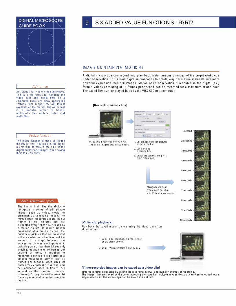
A digital microscope can record and play back instantaneous changes of the target workpiece under observation. This allows digital microscopes to create very persuasive materials with more powerful expression than still images. Motion of an observation is recorded in the digital (AVI) format. Videos consisting of 15 frames per second can be recorded for a maximum of one hour. The saved files can be played back by the VHX-500 or a computer.
24
SIX ADDED VALUE FUNCTIONS - PART29
AVI stands for Audio Video Interleave. This is a file format for handling the video data and audio data on a computer. There are many application software that support the AVI format available on the market. The AVI format is a popular format to handle multimedia files such as video and audio files.
AVI format
The resize function is used to reduce the image size. It is used in the digital microscope to reduce the size of the digital microscope images when saving them to a computer.
Resize function
Play back the saved motion picture using the Menu bar of the album screen.
[Video clip playback]
Image size is recorded by 800 x 600. (The actual imaging area is 800 x 480.)
Maximum one hour recording is possible with 15 frames per second.
[Recording video clips]
1. Click [Record motion picture] on the Menu bar.
2. Set the video recording time.
3. Check the settings and press [Start recording].
1. Select a desired image file (AVI format) on the album screen.
2. Select "Playback" from the Menu bar.
1 second
2 seconds
3 seconds
4 seconds
5 seconds
6 seconds
7 seconds
8 seconds
9 seconds
10 seconds
Timer recording is possible by setting the recording interval and number of times of recording. The images that are saved by the timer recording are stored as multiple images files that can then be edited into a single video clip. The video clips can be saved in an album.
[Timer-recorded images can be saved as a video clip]
Video systems and types
The human brain has the ability to recognize a series of still picture images such as video, movie, or animation as continuing motion. The human brain recognizes more than 2 frames of still pictures that are presented every 1/4 to 1/60 second as a motion picture. To realize smooth movement of a motion picture, the number of pictures that are presented within a certain period of time and the amount of change between the successive pictures are important. A switching time of less than 0.1 second, which is equivalent to 10 frames per second or more, is required to recognize a series of still pictures as a smooth movement. Movies use 24 frames per second, video uses 30 frames (or 25 frames) per second, and cell animation uses 8 frames per second as the standard practice. However, Disney animation uses 24 frames per second to realize smoother motion.
25
3D IMAGE CAPTURING TECHNIQUE
Useful as the reference dimensions during simple measurement and on printout.
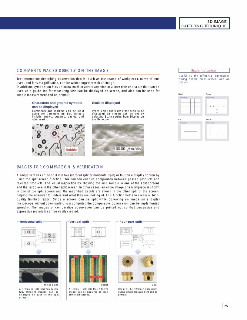
Scale indication COMMENTS PLACED DIRECTLY ON THE IMAGE
Text information describing observation details, such as title (name of workpiece), name of lens used, and lens magnification, can be written together with an image. In addition, symbols such as an arrow mark to attract attention at a later time or a scale that can be used as a guide line for measuring size can be displayed on screen, and also can be used for simple measurement and on printout.
IMAGES FOR COMPARISON & VERIFICATION
A single screen can be split into two (vertical split or horizontal split) or four on a display screen by using the split screen function. This function enables comparison between passed products and rejected products, and visual inspection by showing the limit sample in one of the split screens and the test piece in the other split screen. In other cases, an entire image of a workpiece is shown in one of the split screen and the magnified details are shown in the other split of the screen, helping the observer to understand what they are looking at. This function helps to create a high-quality finished report. Since a screen can be split while observing an image on a digital microscope without downloading to a computer, the comparative observation can be implemented speedily. The images of comparative observation can be printed out so that persuasive and expressive materials can be easily created.
Types, color, and width of the scale to be displayed on screen can be set by selecting Scale setting from Display on the Menu bar.
Scale is displayed
ResistThread blade Gear
A screen is split horizontally into two. Different images can be displayed on each of the split screens.
A screen is split into four. Different images can be displayed on each of the split screens.
Useful as the reference dimensions during simple measurement and on printout.
Four-part splitHorizontal split Vertical split
Mesh Cross
Bar XYBar
Comments and markers can be input using the Comment tool bar. Markers include arrows, squares, circles, and other marks.
Characters and graphic symbols can be displayed
Bubble
DIGITAL MICROSCOPEGUIDE BOOK
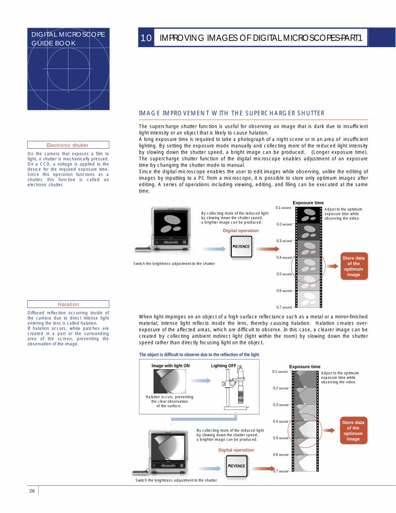
IMAGE IMPROVEMENT WITH THE SUPERCHARGER SHUTTER
The supercharge shutter function is useful for observing an image that is dark due to insufficient light intensity or an object that is likely to cause halation. A long exposure time is required to take a photograph of a night scene or in an area of insufficient lighting. By setting the exposure mode manually and collecting more of the reduced light intensity by slowing down the shutter speed, a bright image can be produced. (Longer exposure time). The supercharge shutter function of the digital microscope enables adjustment of an exposure time by changing the shutter mode to manual. Since the digital microscope enables the user to edit images while observing, unlike the editing of images by inputting to a PC from a microscope, it is possible to store only optimum images after editing. A series of operations including viewing, editing, and filing can be executed at the same time.
26
IMPROVING IMAGES OF DIGITAL MICROSCOPES-PART110
On the camera that exposes a film to light, a shutter is mechanically pressed. On a CCD, a voltage is applied to the device for the required exposure time. Since this operation functions as a shutter, this function is called an electronic shutter.
Electronic shutter
Diffused reflection occurring inside of the camera due to direct intense light entering the lens is called halation. If halation occurs, white patches are created in a part or the surrounding area of the screen, preventing the observation of the image.
Halation
Dark unclear image
By collecting more of the reduced light by slowing down the shutter speed, a brighter image can be produced.
Adjust to the optimum exposure time while observing the video
Switch the brightness adjustment to the shutter
Digital operation
Exposure time
Store data of the
optimum image
0.1 second
0.2 second
0.3 second
0.4 second
0.5 second
0.6 second
0.7 second
When light impinges on an object of a high surface reflectance such as a metal or a mirror-finished material, intense light reflects inside the lens, thereby causing halation. Halation creates over-exposure of the affected areas, which are difficult to observe. In this case, a clearer image can be created by collecting ambient indirect light (light within the room) by slowing down the shutter speed rather than directly focusing light on the object.
Lighting OFF
The object is difficult to observe due to the reflection of the light
Adjust to the optimum exposure time while observing the video
By collecting more of the reduced light by slowing down the shutter speed, a brighter image can be produced.
Switch the brightness adjustment to the shutter
Digital operation
Image with light ON
Halation occurs, preventing the clear observation
of the surface.
Exposure time 0.1 second
0.2 second
0.3 second
0.4 second
0.5 second
0.6 second
0.7 second
Store data of the
optimum image
27
MECHANISM OF DIGITAL IMAGE PROCESSING
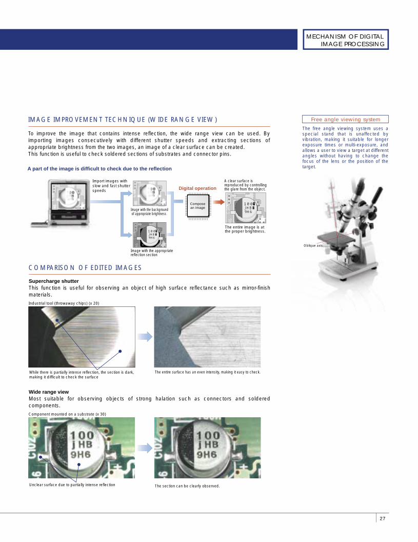
The free angle viewing system uses a special stand that is unaffected by vibration, making it suitable for longer exposure times or multi-exposure, and allows a user to view a target at different angles without having to change the focus of the lens or the position of the target.
Free angle viewing systemIMAGE IMPROVEMENT TECHNIQUE (WIDE RANGE VIEW)
To improve the image that contains intense reflection, the wide range view can be used. By importing images consecutively with different shutter speeds and extracting sections of appropriate brightness from the two images, an image of a clear surface can be created. This function is useful to check soldered sections of substrates and connector pins.
A clear surface is reproduced by controlling the glare from the object.
A part of the image is difficult to check due to the reflection
Import images with slow and fast shutterspeeds
Image with the background of appropriate brightness
Compose an image
Digital operation
The entire image is at the proper brightness.
46C102
J109
100�j HB�9H6
Image with the appropriate reflection section
46C102
J109
100�j HB�9H6
Supercharge shutter This function is useful for observing an object of high surface reflectance such as mirror-finish materials.
COMPARISON OF EDITED IMAGES
Industrial tool (throwaway chips) (x 20)
While there is partially intense reflection, the section is dark, making it difficult to check the surface
The entire surface has an even intensity, making it easy to check.
Wide range view Most suitable for observing objects of strong halation such as connectors and soldered components.
Component mounted on a substrate (x 30)
Unclear surface due to partially intense reflection The section can be clearly observed.
Oblique axis
DIGITAL MICROSCOPEGUIDE BOOK
28
IMPROVING IMAGES OF DIGITAL MICROSCOPES-PART210
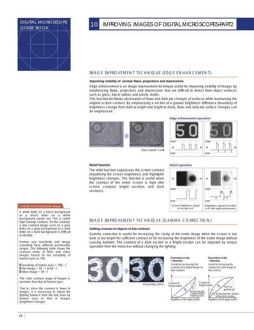
The relief function suppresses the screen contrast (equalizing the screen brightness) and highlights brightness changes. This function is useful when the contrast of the entire screen is high (the screen contains bright sections and dark sections).
Relief function
Black rubber(X25)A A’ A A’
Bright
Dark
Bright
Dark
Edge enhancement operation
A A’
Brightness signal of section A-A' after edge enhancement
A A’
Bright
Dark
Bright
Dark
Relief operation
Screen brightness signal of section A-A'
IMAGE IMPROVEMENT TECHNIQUE (EDGE ENHANCEMENT)
Edge enhancement is an image improvement technique useful for improving visibility of images by emphasizing flaws, projections and depressions that are difficult to detect from object surfaces such as glass, black rubber, and plastic molds. This function facilitates observation of flaws and delicate changes of surfaces while maintaining the original screen contrast. By emphasizing a section of a greater brightness difference (boundary of brightness change from dark to bright and bright to dark), flaws and delicate surface changes can be emphasized.
Improving visibility of unclear flaws, projections and depressions
IMAGE IMPROVEMENT TECHNIQUE (GAMMA CORRECTION)
Gamma correction is useful for increasing the clarity of the entire image when the screen is too dark or too bright for sufficient contrast or for increasing the brightness of the entire image without causing halation. The contrast of a dark section or a bright section can be adjusted by mouse operation from the menu bar without changing the lighting.
Adding contrast to objects of low contrast
Silk printing (200x)
Brightness of the target surface
Increasing the contrast of the bright section
Brightness of the target surface
Increasing the contrast of the dark section
"OFF" or gamma ±0
Useful for increasing the contrast of a bright image of low contrast
Correction in the + direction
Useful for increasing the contrast of a dark image of low contrast
Correction in the - direction
Contrast of image output
Contrast of image output
Contrast and brightness design
A white letter on a black background or a black letter on a white background stands out. This is called high (strong) contrast. On the contrary, a low contrast image such as a gray letter on a gray background or a dark letter on a dark background is difficult to identify.
Human eye sensitivity and image sensitivity have different permissible ranges. The following table shows the contrast ratios of films and video images based on the sensitivity of human eyes as 100.
❙ Sensitivity of human eyes = 100 : 1 ❙ Film image = 50 : 1 to 60 : 1 ❙ Video image = 30 : 1
The color contrast range of images is narrower than that of human eyes.
That is, since the contrast is lower in images, it is necessary to adjust the lighting balance from the one seen by human eyes to that in images (brightness design).
Full illumination mode Partial illumination mode
Full illumination + image enhancement mode
Partial illumination + image enhancement mode
29
MECHANISM OF DIGITAL IMAGE PROCESSING
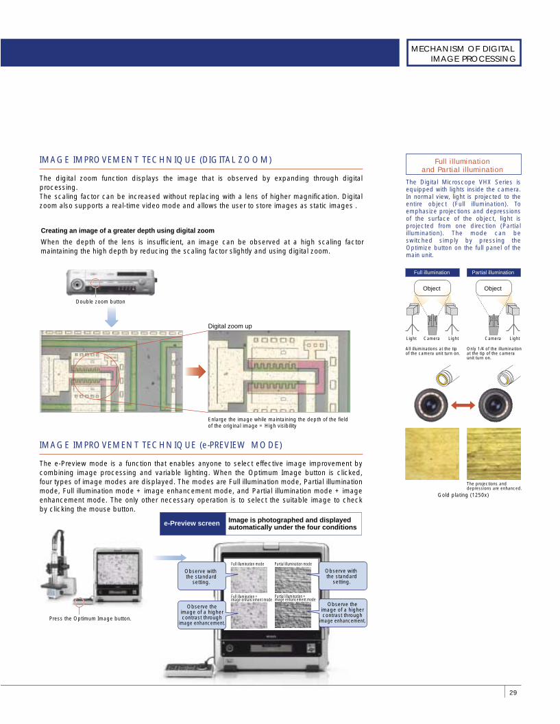
The Digital Microscope VHX Series is equipped with lights inside the camera. In normal view, light is projected to the entire object (Full illumination). To emphasize projections and depressions of the surface of the object, light is projected from one direction (Partial illumination). The mode can be switched simply by pressing the Optimize button on the full panel of the main unit.
Full illumination and Partial illumination
IMAGE IMPROVEMENT TECHNIQUE (DIGITAL ZOOM)
The digital zoom function displays the image that is observed by expanding through digital processing. The scaling factor can be increased without replacing with a lens of higher magnification. Digital zoom also supports a real-time video mode and allows the user to store images as static images .
When the depth of the lens is insufficient, an image can be observed at a high scaling factor maintaining the high depth by reducing the scaling factor slightly and using digital zoom.
Creating an image of a greater depth using digital zoom
Double zoom button
Digital zoom up
Enlarge the image while maintaining the depth of the field of the original image = High visibility
IMAGE IMPROVEMENT TECHNIQUE (e-PREVIEW MODE)
The e-Preview mode is a function that enables anyone to select effective image improvement by combining image processing and variable lighting. When the Optimum Image button is clicked, four types of image modes are displayed. The modes are Full illumination mode, Partial illumination mode, Full illumination mode + image enhancement mode, and Partial illumination mode + image enhancement mode. The only other necessary operation is to select the suitable image to check by clicking the mouse button.
Press the Optimum Image button.
Observe with the standard
setting.
Observe the image of a higher contrast through
image enhancement.
Observe with the standard
setting.
Observe the image of a higher contrast through
image enhancement.
Image is photographed and displayed automatically under the four conditionse-Preview screen
Full illumination Partial illumination
Only 1/4 of the illumination at the tip of the camera unit turn on.
All illuminations at the tip of the camera unit turn on.
Camera Light
Object
Camera LightLight
Object
Gold plating (1250x)
The projections and depressions are enhanced.
DIGITAL MICROSCOPEGUIDE BOOK
COMPUTER NETWORKS
HOW TO UTILIZE A DIGITAL MICROSCOPE ON A NETWORK
LAN (Local area Network)
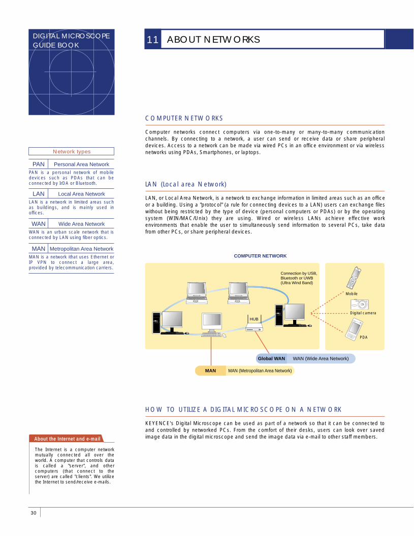
Computer networks connect computers via one-to-many or many-to-many communication channels. By connecting to a network, a user can send or receive data or share peripheral devices. Access to a network can be made via wired PCs in an office environment or via wireless networks using PDAs, Smartphones, or laptops.
LAN, or Local Area Network, is a network to exchange information in limited areas such as an office or a building. Using a "protocol" (a rule for connecting devices to a LAN) users can exchange files without being restricted by the type of device (personal computers or PDAs) or by the operating system (WIN/MAC/Unix) they are using. Wired or wireless LANs achieve effective work environments that enable the user to simultaneously send information to several PCs, take data from other PCs, or share peripheral devices.
KEYENCE's Digital Microscope can be used as part of a network so that it can be connected to and controlled by networked PCs. From the comfort of their desks, users can look over saved image data in the digital microscope and send the image data via e-mail to other staff members.About the Internet and e-mail
The Internet is a computer network mutually connected all over the world. A computer that controls data is called a "server", and other computers (that connect to the server) are called "clients". We utilize the Internet to send/receive e-mails.
30
ABOUT NETWORKS11
COMPUTER NETWORK
Mobile
Digital camera
PDA
MAN (Metropolitan Area Network)MAN
WAN (Wide Area Network)Global WAN
Connection by USB, Bluetooth or UWB (Ultra Wind Band)
Network types
PAN is a personal network of mobile devices such as PDAs that can be connected by IrDA or Bluetooth.
PAN Personal Area Network
LAN is a network in limited areas such as buildings, and is mainly used in offices.
LAN Local Area Network
WAN is an urban scale network that is connected by LAN using fiber optics.
WAN Wide Area Network
MAN is a network ithat uses Ethernet or IP VPN to connect a large area, provided by telecommunication carriers.
MAN Metropolitan Area Network
HUB
31
NETWORK APPLICATIONS
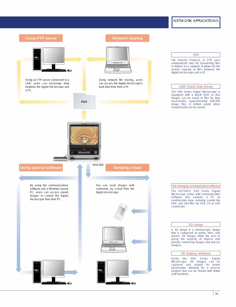
Using an FTP server connected to a LAN, users can exchange data between the digital microscope and a PC.
By using the communications software and a Windows based PC, users can access stored images or control the digital microscope from their PC.
Sending e-mailUsing special software
Network sharing
Using network file sharing, users can access the digital microscope's hard disk drive from a PC
You can send images with comments by e-mail from the digital microscope.
VHX-600
FILE
Using FTP server
File Transfer Protocol, or FTP, uses standardized rules for transferring files or folders on a network. It allows for the mutual copying of files between the digital microscope and a PC.
FTP
The VHX Series Digital Microscope is equipped with a 40GB HDD so that images can be saved to files for later observation. Approximately 200,000 image files (2 million pixels when compressed) can be saved.
HDD (Hard Disk Drive)
The KEYENCE VHX Series Digital Microscope comes with communication software that enables a PC to send/receive data, remotely control the VHX, and edit files via USB 2.0 or LAN connection.
File managing (communication) software
Using the VHX Series Digital Microscope, 3D images can be captured and angled for better observation allowing for a precise analysis that can be shared with fellow staff members.
3D display software
A 3D image is a stereoscopic image that is composed of points, lines, and planes. 3D images allow the user to grasp the asperity of objects and provide convincing images and precise analysis.
3D image
DIGITAL MICROSCOPEGUIDE BOOK
SAVING PHOTOGRAPHED IMAGES TO A DIGITAL MICROSCOPE
OBSERVING IMAGES ON SEVERAL OFFICE PCs
QUICK IMAGE DOWNLOAD TO A PC
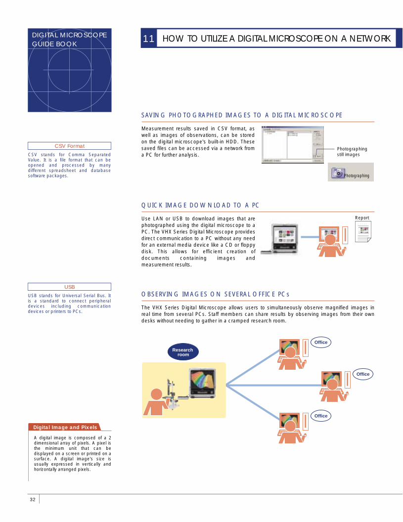
Measurement results saved in CSV format, as well as images of observations, can be stored on the digital microscope's built-in HDD. These saved files can be accessed via a network from a PC for further analysis.
Use LAN or USB to download images that are photographed using the digital microscope to a PC. The VHX Series Digital Microscope provides direct communication to a PC without any need for an external media device like a CD or floppy disk. This allows for efficient creation of documents containing images and measurement results.
The VHX Series Digital Microscope allows users to simultaneously observe magnified images in real time from several PCs. Staff members can share results by observing images from their own desks without needing to gather in a cramped research room.
Digital Image and Pixels
A digital image is composed of a 2 dimensional array of pixels. A pixel is the minimum unit that can be displayed on a screen or printed on a surface. A digital image's size is usually expressed in vertically and horizontally arranged pixels.
32
HOW TO UTILIZE A DIGITAL MICROSCOPE ON A NETWORK11
USB stands for Universal Serial Bus. It is a standard to connect peripheral devices including communication devices or printers to PCs.
USB
CSV stands for Comma Separated Value. It is a file format that can be opened and processed by many different spreadsheet and database software packages.
CSV Format Photographing still images
Report○○○○○�
Office
Research room
Office
Office
Photographing
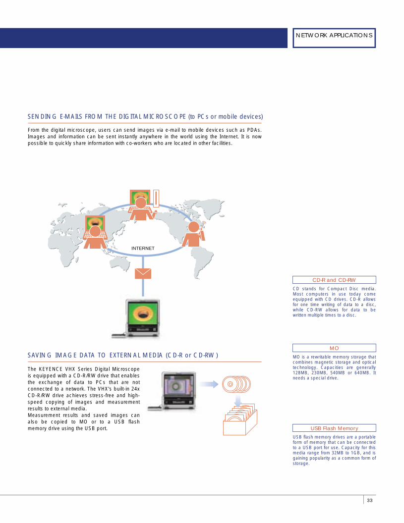
SENDING E-MAILS FROM THE DIGITAL MICROSCOPE (to PCs or mobile devices)
From the digital microscope, users can send images via e-mail to mobile devices such as PDAs. Images and information can be sent instantly anywhere in the world using the Internet. It is now possible to quickly share information with co-workers who are located in other facilities.
33
NETWORK APPLICATIONS
INTERNET
CD stands for Compact Disc media. Most computers in use today come equipped with CD drives. CD-R allows for one time writing of data to a disc, while CD-RW allows for data to be written multiple times to a disc.
CD-R and CD-RW
MO is a rewritable memory storage that combines magnetic storage and optical technology. Capacities are generally 128MB, 230MB, 540MB or 640MB. It needs a special drive.
MO
USB flash memory drives are a portable form of memory that can be connected to a USB port for use. Capacity for this media range from 32MB to 1GB, and is gaining popularity as a common form of storage.
USB Flash Memory
SAVING IMAGE DATA TO EXTERNAL MEDIA (CD-R or CD-RW)
The KEYENCE VHX Series Digital Microscope is equipped with a CD-R/RW drive that enables the exchange of data to PCs that are not connected to a network. The VHX's built-in 24x CD-R/RW drive achieves stress-free and high-speed copying of images and measurement results to external media.Measurement results and saved images can also be copied to MO or to a USB flash memory drive using the USB port.
DIGITAL MICROSCOPEGUIDE BOOK
SPECIAL COMMUNICATION SOFTWARE
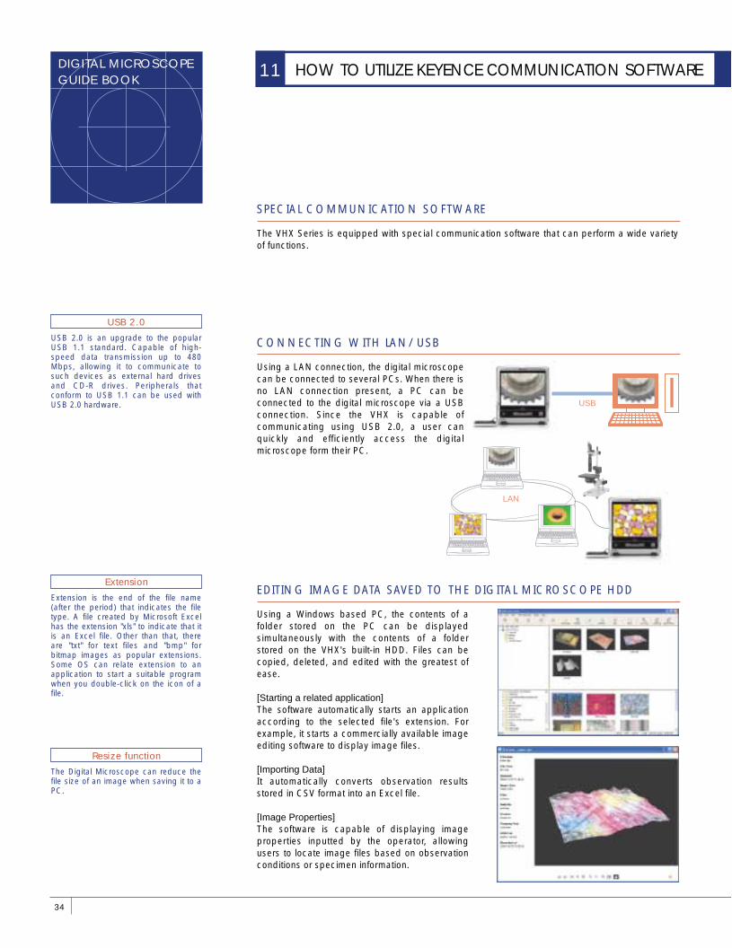
EDITING IMAGE DATA SAVED TO THE DIGITAL MICROSCOPE HDD
CONNECTING WITH LAN/USB
The VHX Series is equipped with special communication software that can perform a wide variety of functions.
Using a LAN connection, the digital microscope can be connected to several PCs. When there is no LAN connection present, a PC can be connected to the digital microscope via a USB connection. Since the VHX is capable of communicating using USB 2.0, a user can quickly and efficiently access the digital microscope form their PC.
Using a Windows based PC, the contents of a folder stored on the PC can be displayed simultaneously with the contents of a folder stored on the VHX's built-in HDD. Files can be copied, deleted, and edited with the greatest of ease.
[Starting a related application]The software automatically starts an application according to the selected file's extension. For example, it starts a commercially available image editing software to display image files.
[Importing Data]It automatically converts observation results stored in CSV format into an Excel file.
[Image Properties]The software is capable of displaying image properties inputted by the operator, allowing users to locate image files based on observation conditions or specimen information.
34
HOW TO UTILIZE KEYENCE COMMUNICATION SOFTWARE11
USB 2.0 is an upgrade to the popular USB 1.1 standard. Capable of high-speed data transmission up to 480 Mbps, allowing it to communicate to such devices as external hard drives and CD-R drives. Peripherals that conform to USB 1.1 can be used with USB 2.0 hardware.
USB 2.0
Extension is the end of the file name (after the period) that indicates the file type. A file created by Microsoft Excel has the extension "xls" to indicate that it is an Excel file. Other than that, there are "txt" for text files and "bmp" for bitmap images as popular extensions. Some OS can relate extension to an application to start a suitable program when you double-click on the icon of a file.
Extension
The Digital Microscope can reduce the file size of an image when saving it to a PC.
Resize function
LAN
USB
REMOTELY CONTROLLING THE DIGITAL MICROSCOPE
The images that can be observed with the digital microscope can be displayed or saved to a PC. Users can also observe a process by using the Timer Recording function and have the ability to remotely power off the unit.
35
NETWORK APPLICATIONS
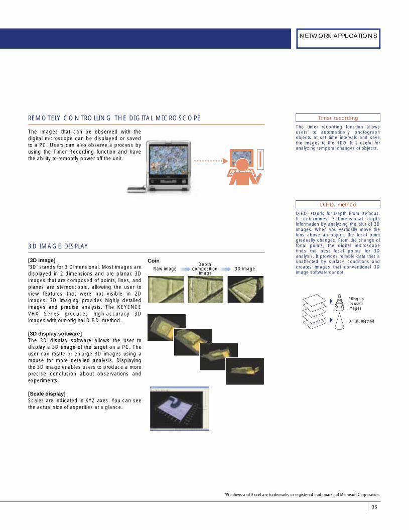
3D IMAGE DISPLAY
[3D image]"3D" stands for 3 Dimensional. Most images are displayed in 2 dimensions and are planar. 3D images that are composed of points, lines, and planes are stereoscopic, allowing the user to view features that were not visible in 2D images. 3D imaging provides highly detailed images and precise analysis. The KEYENCE VHX Series produces high-accuracy 3D images with our original D.F.D. method.
[3D display software]The 3D display software allows the user to display a 3D image of the target on a PC. The user can rotate or enlarge 3D images using a mouse for more detailed analysis. Displaying the 3D image enables users to produce a more precise conclusion about observations and experiments.
[Scale display]Scales are indicated in XYZ axes. You can see the actual size of asperities at a glance.
The timer recording function allows users to automatically photograph objects at set time intervals and save the images to the HDD. It is useful for analyzing temporal changes of objects.
Timer recording
D.F.D. stands for Depth From Defocus. It determines 3-dimensional depth information by analyzing the blur of 2D images. When you vertically move the lens above an object, the focal point gradually changes. From the change of focal points, the digital microscope finds the best focal points for 3D analysis. It provides reliable data that is unaffected by surface conditions and creates images that conventional 3D image software cannot.
D.F.D. method
D.F.D. method
Piling up focused images
CoinRaw image
Depth composition
image3D image
*Windows and Excel are trademarks or registered trademarks of Microsoft Corporation.