optimization of composite layers lay-up of an aeronautical
TRANSCRIPT
Optimization of Composite layers lay-up of an aeronautical component using an ISight-
based intelligent decision advisor, iDA
Luca Fattore Exemplar srl
[email protected] www.exemplar.com
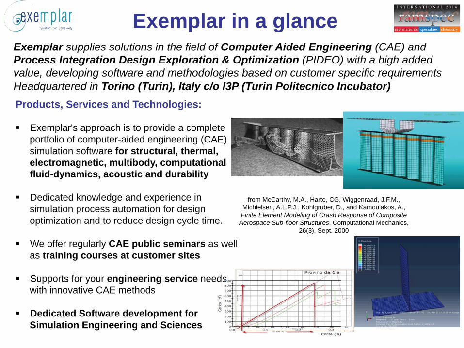
Exemplar in a glance Exemplar supplies solutions in the field of Computer Aided Engineering (CAE) and Process Integration Design Exploration & Optimization (PIDEO) with a high added value, developing software and methodologies based on customer specific requirements Headquartered in Torino (Turin), Italy c/o I3P (Turin Politecnico Incubator) Products, Services and Technologies: Exemplar's approach is to provide a complete
portfolio of computer-aided engineering (CAE) simulation software for structural, thermal, electromagnetic, multibody, computational fluid-dynamics, acoustic and durability
Dedicated knowledge and experience in
simulation process automation for design optimization and to reduce design cycle time.
We offer regularly CAE public seminars as well
as training courses at customer sites Supports for your engineering service needs
with innovative CAE methods Dedicated Software development for
Simulation Engineering and Sciences
from McCarthy, M.A., Harte, CG, Wiggenraad, J.F.M., Michielsen, A.L.P.J., Kohlgruber, D., and Kamoulakos, A., Finite Element Modeling of Crash Response of Composite Aerospace Sub-floor Structures, Computational Mechanics,
26(3), Sept. 2000
edssssssssssssssssssssssssssssssssssssssssssssssssssssssssssssssssssssssssssssssssssssssssssssssssssssssssssssssssssssssssssssssssssssss
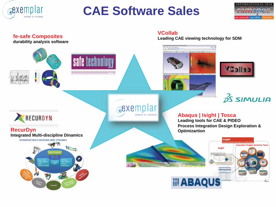
CAE Software Sales
fe-safe Composites durability analysis software
VCollab Leading CAE viewing technology for SDM
RecurDyn Integrated Multi-discipline Dinamics
Abaqus | Isight | Tosca Leading tools for CAE & PIDEO Process Integration Design Exploration & Optimizartion
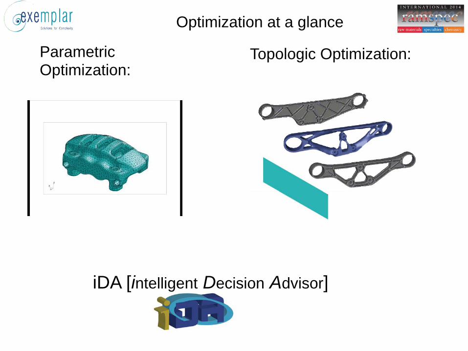
Optimization at a glance
Parametric Optimization:
Topologic Optimization:
iDA [intelligent Decision Advisor]
iDA introduction
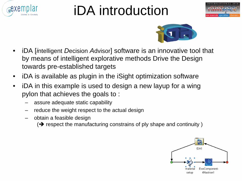
• iDA [intelligent Decision Advisor] software is an innovative tool that
by means of intelligent explorative methods Drive the Design towards pre-established targets
• iDA is available as plugin in the iSight optimization software • iDA in this example is used to design a new layup for a wing
pylon that achieves the goals to : – assure adequate static capability – reduce the weight respect to the actual design – obtain a feasible design
( respect the manufacturing constrains of ply shape and continuity )
2
3
4
5
6
7
8
1 11 21 31 41 51 61 71 81 91 101 111 121 131step
mas
s to
t [kg
]
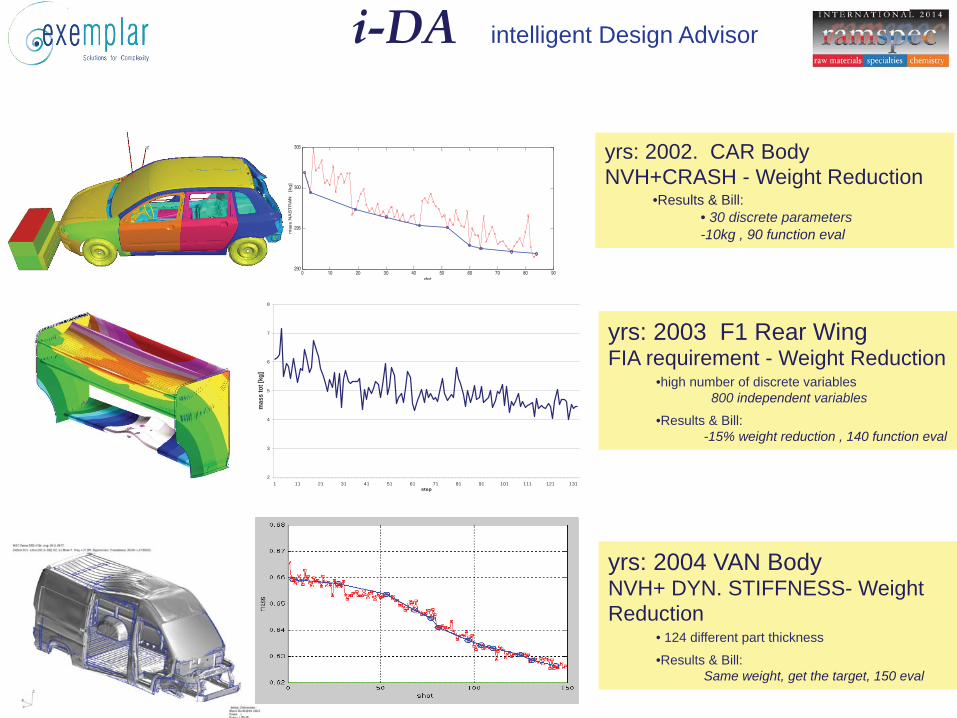
yrs: 2003 F1 Rear Wing FIA requirement - Weight Reduction
• high number of discrete variables 800 independent variables
• Results & Bill: -15% weight reduction , 140 function eval
i-DA intelligent Design Advisor
0 10 20 30 40 50 60 70 80 90290
295
300
305
mas
s N
AS
TR
AN
[kg]
shot
yrs: 2002. CAR Body NVH+CRASH - Weight Reduction
• Results & Bill: • 30 discrete parameters -10kg , 90 function eval
yrs: 2004 VAN Body NVH+ DYN. STIFFNESS- Weight Reduction
• 124 different part thickness
• Results & Bill: Same weight, get the target, 150 eval
0 500 1000 1500 2000 25001100
1200
1300
1400
1500
1600
1700
1800
1900
2000
mass
shot
i-DA intelligent Design Advisor
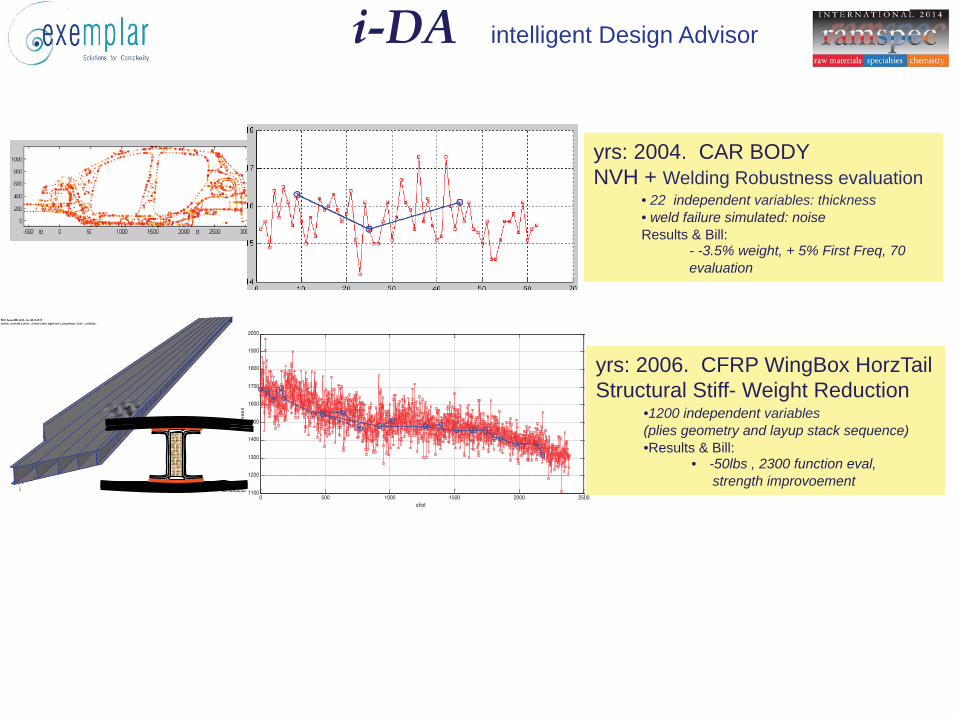
yrs: 2006. CFRP WingBox HorzTail Structural Stiff- Weight Reduction
• 1200 independent variables (plies geometry and layup stack sequence) • Results & Bill:
• -50lbs , 2300 function eval, strength improvoement
mass
yrs: 2004. CAR BODY NVH + Welding Robustness evaluation
• 22 independent variables: thickness • weld failure simulated: noise Results & Bill:
- -3.5% weight, + 5% First Freq, 70 evaluation
i-DA intelligent Design Advisor
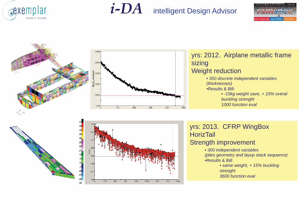
yrs: 2013. CFRP WingBox HorizTail Strength improvement
• 300 independent variables (plies geometry and layup stack sequence) • Results & Bill:
• same weight, + 15% buckling strenght 3600 function eval
yrs: 2012. Airplane metallic frame sizing Weight reduction
• 350 discrete independent variables (thicknesses) • Results & Bill:
• -15kg weight save, + 15% overal buckling strenght 1000 function eval
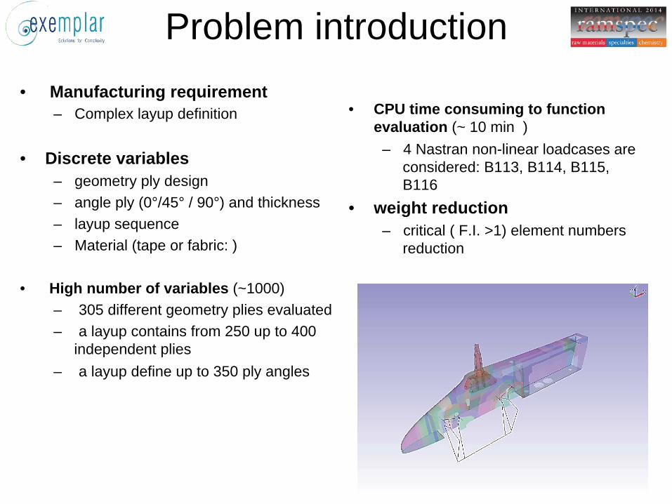
Problem introduction • Manufacturing requirement
– Complex layup definition
• Discrete variables – geometry ply design – angle ply (0°/45° / 90°) and thickness – layup sequence – Material (tape or fabric: )
• High number of variables (~1000) – 305 different geometry plies evaluated – a layup contains from 250 up to 400
independent plies – a layup define up to 350 ply angles
• CPU time consuming to function evaluation (~ 10 min )
– 4 Nastran non-linear loadcases are considered: B113, B114, B115, B116
• weight reduction – critical ( F.I. >1) element numbers
reduction

Why ? • The multi-disciplinary optimization problem dramatically
increase the design parameter: in the real world, the number of design parameter is huge, and only an efficient exploration of their interaction can achieve a innovation design.
• For engineering problems many optimization method are available. EXEMPLAR experienced that all of them have a limited number of design parameter, because they are “generic” method. The multi-objective method require many computational effort, and can become prohibitive with high input parameter number
• In the classical optimization methods, the user cannot supply some of his knowledge about the problem.
• The aim of iDA algorithm is allow the expert to supply all useful information to drive the exploration method to reach its goals.
The method
TARGET PERFORMANCE
Design var.2
mas
s
mas
s
Design limits
Design var.1
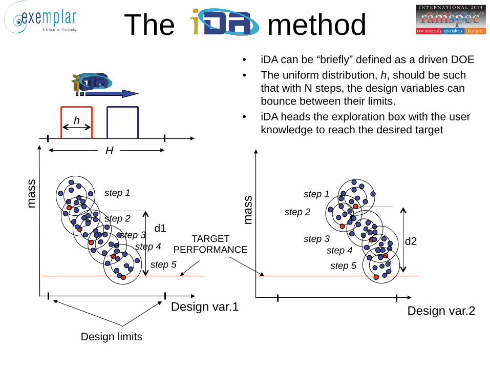
• iDA can be “briefly” defined as a driven DOE • The uniform distribution, h, should be such
that with N steps, the design variables can bounce between their limits.
• iDA heads the exploration box with the user knowledge to reach the desired target
H
h
step 1 step 1
d1 d2
step 2 step 2
step 3 step 3 step 4 step 4
step 5 step 5
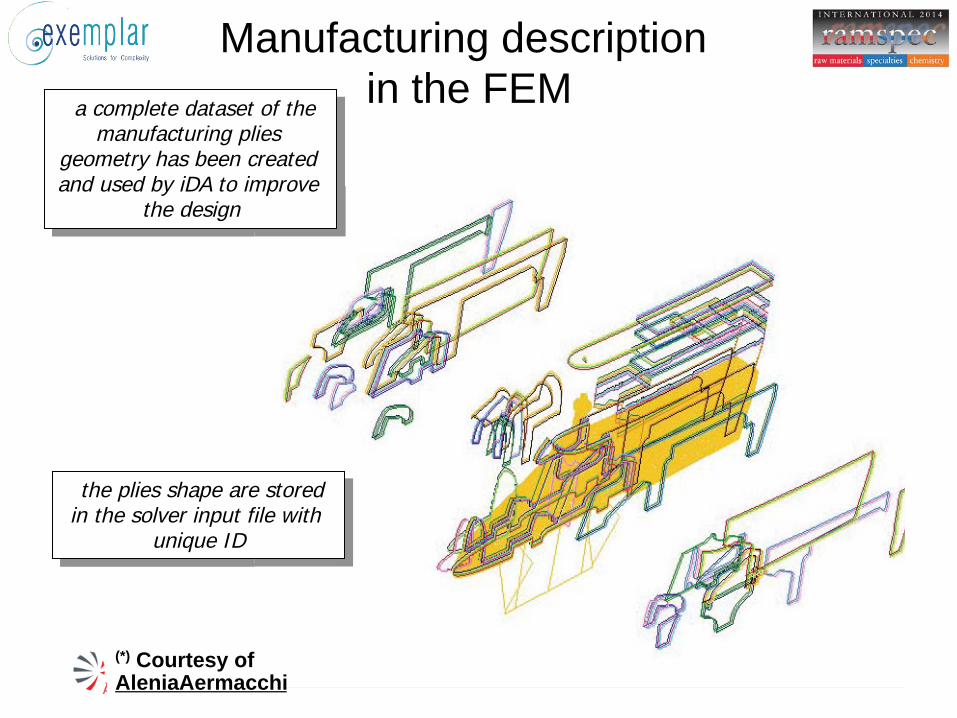
Manufacturing description in the FEM a complete dataset of the
manufacturing plies geometry has been created and used by iDA to improve
the design
(*) Courtesy of AleniaAermacchi
the plies shape are stored in the solver input file with
unique ID

GLOBAL LAYUP SEQUENCE: the independent plies
Ply_shape_#1000 Ply_shape_#1010 Ply_shape_#1012 Ply_shape_#1020 Ply_shape_#1000 Ply_shape_#2040 Ply_shape_#2045
Ply_shape_#2044 Ply_shape_#1072 Ply_shape_#1045
angle=0° angle=0° angle=0° angle=0° angle=0° angle=0° angle=0°
angle=0° angle=0° angle=0°
Mat=A Mat=A Mat=A Mat=A Mat=A Mat=A Mat=A
Mat=A Mat=A Mat=A
Ply_shape_#2040 Ply_shape_#2045
Ply_shape_#2044 Ply_shape_#1072 Ply_shape_#1045
angle=0° angle=0°
angle=0° angle=0° angle=0°
Mat=A Mat=A
Mat=A Mat=A Mat=A
PLY NAME ANGLE MATERIAL
STEP -0- : initial configuration
and composite
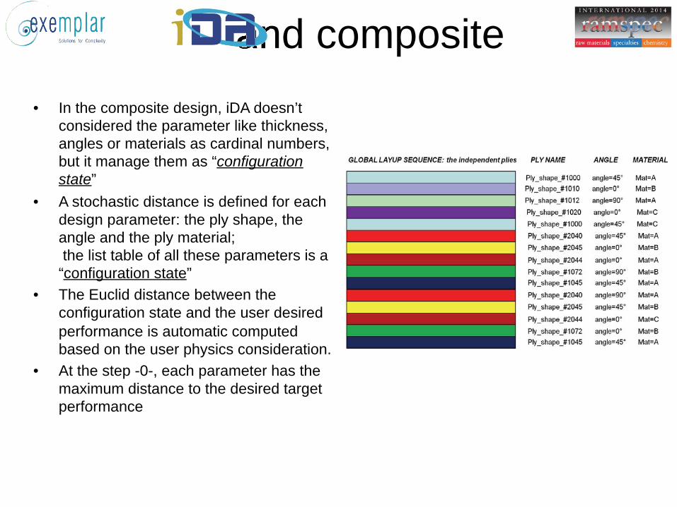
• In the composite design, iDA doesn’t considered the parameter like thickness, angles or materials as cardinal numbers, but it manage them as “configuration state”
• A stochastic distance is defined for each design parameter: the ply shape, the angle and the ply material; the list table of all these parameters is a “configuration state”
• The Euclid distance between the configuration state and the user desired performance is automatic computed based on the user physics consideration.
• At the step -0-, each parameter has the maximum distance to the desired target performance
and composite

GLOBAL LAYUP SEQUENCE: the independent plies
Ply_shape_#1000 Ply_shape_#1010 Ply_shape_#1012 Ply_shape_#1020 Ply_shape_#1000 Ply_shape_#2040 Ply_shape_#2045
Ply_shape_#2044 Ply_shape_#1072 Ply_shape_#1045
angle=0° angle=0° angle=0° angle=0° angle=0° angle=0° angle=0°
angle=0° angle=0° angle=0°
Mat=A Mat=A Mat=A Mat=A Mat=A Mat=A Mat=A
Mat=A Mat=A Mat=A
Ply_shape_#2040 Ply_shape_#2045
Ply_shape_#2044 Ply_shape_#1072 Ply_shape_#1045
angle=0° angle=0°
angle=0° angle=0° angle=0°
Mat=A Mat=A
Mat=A Mat=A Mat=A
PLY NAME ANGLE MATERIAL
STEP -1- : first design exploration
Ply_shape_#1000 angle=0° Mat=A
angle=45°
Mat=C
perfo
rman
ce
and composite
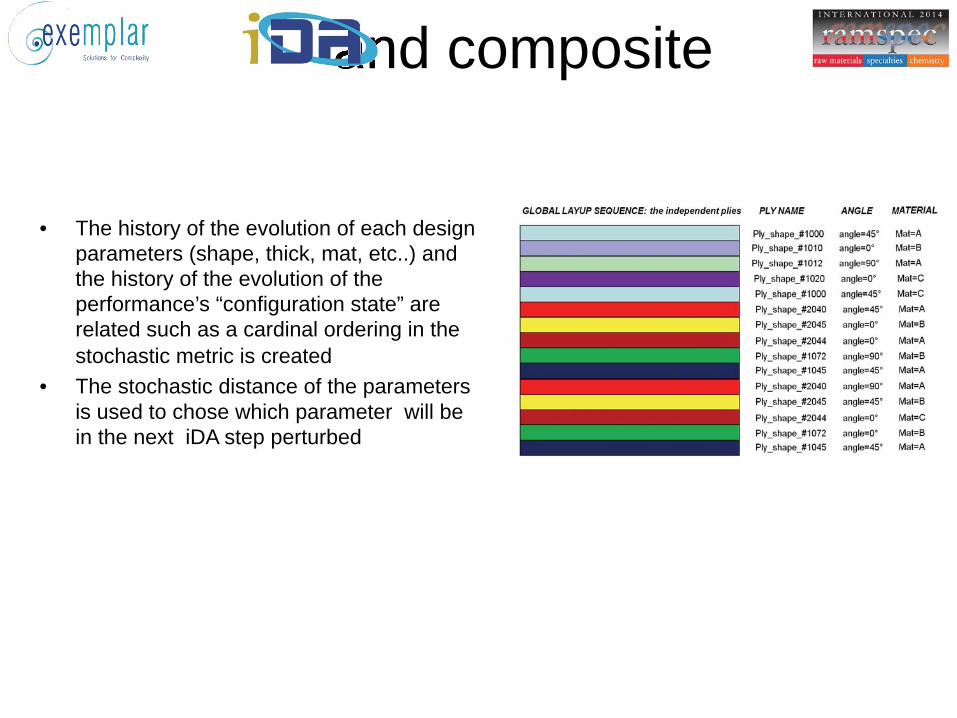
• The history of the evolution of each design parameters (shape, thick, mat, etc..) and the history of the evolution of the performance’s “configuration state” are related such as a cardinal ordering in the stochastic metric is created
• The stochastic distance of the parameters is used to chose which parameter will be in the next iDA step perturbed
and composite
GLOBAL LAYUP SEQUENCE: the independent plies
Ply_shape_#1000 Ply_shape_#1010 Ply_shape_#1012 Ply_shape_#1020 Ply_shape_#1000
Ply_shape_#2045
Ply_shape_#2044 Ply_shape_#1072 Ply_shape_#1045
angle=0° angle=0° angle=0° angle=0° angle=0°
angle=0°
angle=0° angle=0°
Mat=A Mat=A Mat=A Mat=A Mat=A
Mat=A
Mat=A Mat=A Mat=A
Ply_shape_#2040 Ply_shape_#2045
Ply_shape_#2044 Ply_shape_#1072 Ply_shape_#1045
angle=0° angle=0°
angle=0° angle=0° angle=0°
Mat=A
Mat=A Mat=A Mat=A
PLY NAME ANGLE MATERIAL
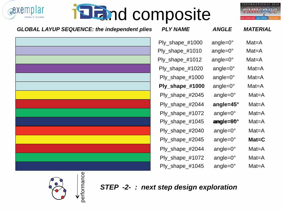
STEP -2- : next step design exploration
Ply_shape_#1000 angle=0° Mat=A
angle=45°
Mat=C
perfo
rman
ce
angle=90°
and composite
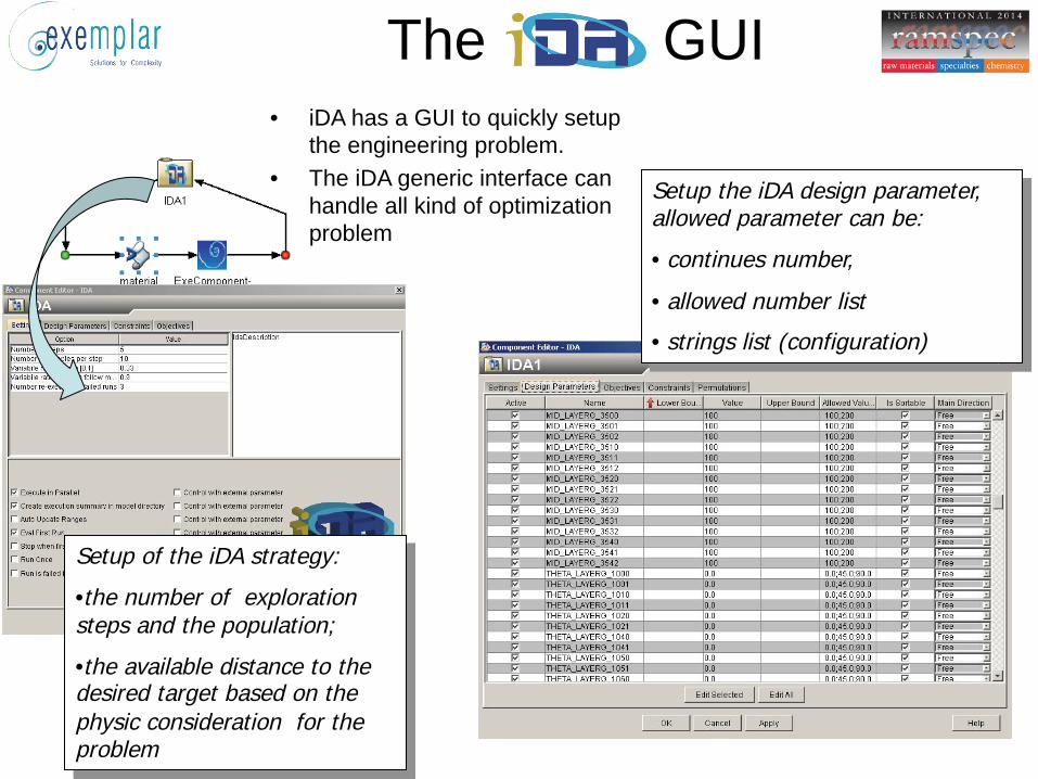
The GUI • iDA has a GUI to quickly setup
the engineering problem. • The iDA generic interface can
handle all kind of optimization problem
Setup of the iDA strategy:
• the number of exploration steps and the population;
• the available distance to the desired target based on the physic consideration for the problem
Setup the iDA design parameter, allowed parameter can be:
• continues number,
• allowed number list
• strings list (configuration)

The wing pylon
• The composite weight is the 70% of the total wing pylon weight
• The total amount of parameters involved are 990 : – i. Number of plies in a given orientation – ii. Ply orientation angle – iii. Ply stacking sequence – iv. Ply material (e.g. Tape or Fabric) – v. Ply shape and position
• Objective and Constrains of the iDA: Reduce the wing pylon mass of the model: mass < actual weight Nastran max Failure index on the laminate [max F.I. < 1] :
it has been introduced a counter of the element failing the criteria: the constrains are to reduce the element with F.I.>1
- (critical element are allowed only at the pins location)
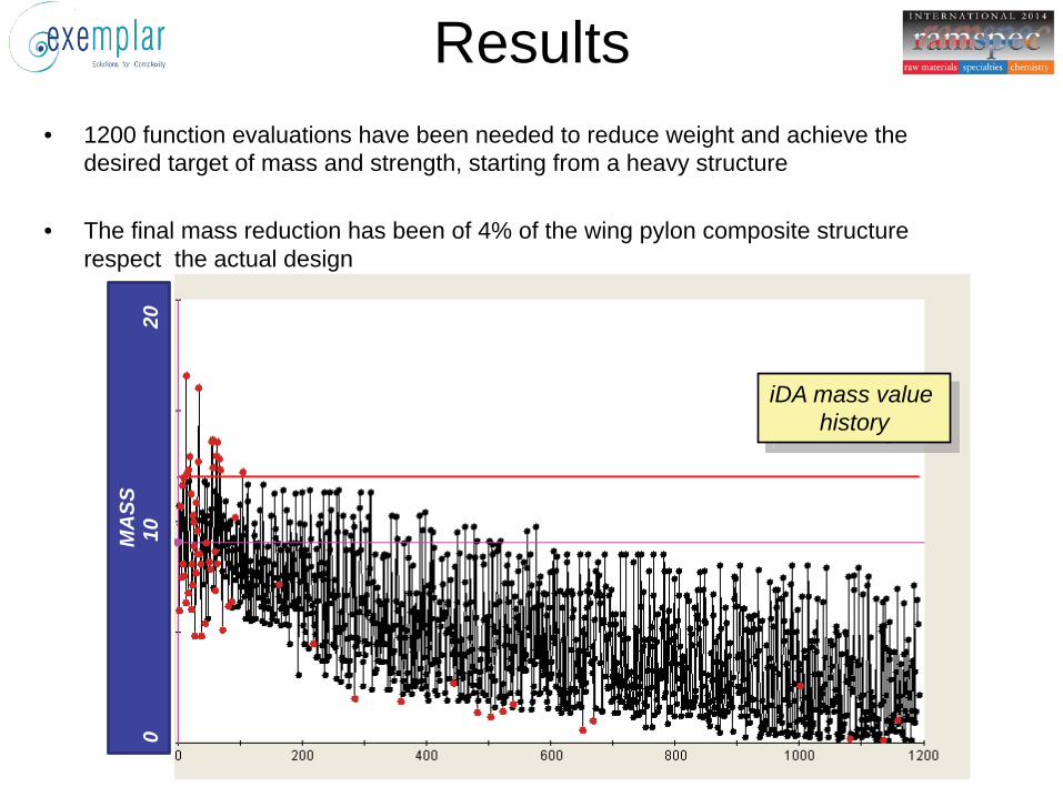
Results • 1200 function evaluations have been needed to reduce weight and achieve the
desired target of mass and strength, starting from a heavy structure
• The final mass reduction has been of 4% of the wing pylon composite structure respect the actual design
iDA mass value history
MA
SS
0
1
0
2
0
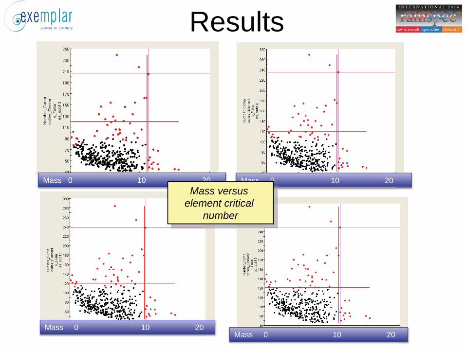
Results
Mass 0 10 20
Mass 0 10 20
Mass 0 10 20
Mass 0 10 20
Mass versus element critical
number
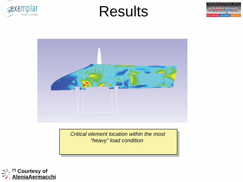
Results
Critical element location within the most “heavy” load condition
(*) Courtesy of AleniaAermacchi
Conclusion • The wing pylon has been optimized manually
through many iteration, spending 2 man months of an expert engineering
• The mass reduction obtained from iDA has been of the 4% less than to the manual design, but:
• it has been obtained automatically starting from a new structure that is 100% heavy
• The result structure show a major strength (less critical “red zones”) due an accurate angle position

• Q&A