optimisation of the nuclear reactor neutron spectrum for ...web.mit.edu/sdon/www/finalpaper.pdf ·...
TRANSCRIPT

Optimisation of the Nuclear Reactor Neutron Spectrumfor the Transmutation of Am241 and Np237
Sarah M. Don
under the direction ofProfessor Michael J. Driscoll and Bo Feng
Nuclear Science and Engineering DepartmentMassachusetts Institute of Technology
Research Science InstituteJuly 29, 2008

Abstract
Nuclear energy is increasing in popularity, and so the amount of nuclear waste in tem-
porary storage is also increasing. One way to reduce the amount of nuclear waste is to
recycle it. The objective of this investigation was to identify the optimal coolant/moderator
density in a PWR in order to destroy the greatest amount of Am241 and Np237 in a modified
MOX fuel assembly. Recycling by adding 12.8% transuranics to a MOX fuel assembly in a
core containing 100% coolant/moderator density transmuted a greater amount of Am241 and
Np237 than a lesser amount of moderator. By transmuting more Am241 in the fuel assembly,
less Np237 is formed from the decay of Am241 after the fuel is removed from the core. This
method of recycling transuranics in MOX fuel reduces the radiotoxicity of the final waste
and permits more storage options.

Contents
1 Introduction 3
1.1 Nuclear Waste Constituants . . . . . . . . . . . . . . . . . . . . . . . . . . . 3
1.2 Recycling . . . . . . . . . . . . . . . . . . . . . . . . . . . . . . . . . . . . . 3
1.3 Fast vs. Thermal Reactors . . . . . . . . . . . . . . . . . . . . . . . . . . . . 4
1.4 Pressurised Light-Water Reactors . . . . . . . . . . . . . . . . . . . . . . . . 4
1.5 CASMO . . . . . . . . . . . . . . . . . . . . . . . . . . . . . . . . . . . . . . 5
1.6 MCNP . . . . . . . . . . . . . . . . . . . . . . . . . . . . . . . . . . . . . . . 6
2 Method 6
2.1 Standard UO2 Case . . . . . . . . . . . . . . . . . . . . . . . . . . . . . . . . 7
2.2 Modified MOX Composition . . . . . . . . . . . . . . . . . . . . . . . . . . . 7
2.3 Matching Burnup . . . . . . . . . . . . . . . . . . . . . . . . . . . . . . . . . 8
2.4 Relative Percent Burnup of Am241 and Np237 . . . . . . . . . . . . . . . . . . 8
2.5 Neutron Spectra at Varying Coolant/Moderator Densities . . . . . . . . . . . 8
3 Results 9
3.1 Amount of Transuranics Required to Achieve Burnup at 40 MWd/kg . . . . 9
3.2 Destruction of Am241 and Np237 . . . . . . . . . . . . . . . . . . . . . . . . . 10
3.3 Neutron Spectra . . . . . . . . . . . . . . . . . . . . . . . . . . . . . . . . . . 11
4 Analysis 11
4.1 Adjustments to the Amount of Transuranics in MOX Fuel . . . . . . . . . . 11
4.2 Destruction of Am241 and Np237 . . . . . . . . . . . . . . . . . . . . . . . . . 12
4.3 Neutron Spectra Comparison . . . . . . . . . . . . . . . . . . . . . . . . . . 13
4.4 Destruction of Am241 and Np237 by Extended Irradiation . . . . . . . . . . . 14
1

5 Waste Disposal Options for Radiotoxic Nuclides 15
6 Conclusion 15
7 Acknowledgements 16
A Definition of k∞ 18
B CASMO Input - 100% Coolant 12.8% Transuranics 19
C Number Densities of Burnable Nuclides 21
D Wt% of Nuclides 22
E Change in k∞ over 60 MWd/kg 23
F MCNP Input 24
2

1 Introduction
Nuclear power is becoming more prevalent in many countries around the world as the price of
fossil fuels continues to rise. However, nuclear power’s many benefits are often overshadowed
by the complications of nuclear waste disposal.
In this theoretical investigation, the transmutation1 of nuclides in a MOX (see Section
1.2) fuel assembly over the course of 60 MWd/kg2 burnup3 in a pressurised water reactor
was simulated using CASMO (see Section 1.5) with each case, the coolant/moderator density
was varied in order to find the optimum neutron spectrum for destroying Am241.
1.1 Nuclear Waste Constituants
Uranium, neptunium, plutonium, curium, californium, and americium are the most prevalent
actinides produced by nuclear fission. These elements are problematic because of their
radioactivity and extremely long half-lives. Am241, in particular, decays to Np237 (as shown
in Figure 1), which has a half-life of 2.144× 10⁶ years[3], and thus determines the long-term
radiotoxicity of the nuclear waste. If the amount of Am241 in the spent fuel is reduced, then
the part of the spent fuel that cannot be recycled can be more easily stored.
1.2 Recycling
One approach to reducing the long-term radiotoxicity of spent nuclear fuel involves recycling
some of the more radiotoxic nuclides by adding them to a MOX (heavy metal oxide) fuel
assembly. MOX fuel consists of the Pu vector from spent LWR (light water reactor) fuel
added to depleated or natural uranium. MOX assemblies that can be used in LWR cores
which normally run on uranium oxide (UO2 or “UOX”) fuel. As these minor actinides are
1the process of an atom decaying or capturing neutrons, causing it to become another isotope or element2mega watt days per kilogram - SI units for burnup3length of time a fuel assembly spends inside the core of the reactor while nuclear fission occurs
3

Figure 1: Decay of Am241 into Np237
exposed to the neutron thermal flux of LWRs, they capture neutrons or undergo fission,
becoming less radiotoxic isotopes. This in turn makes disposal of the spent fuel much easier.
In this investigation, the transuranics in the waste from a uranium oxdide fuel assembly
were added to a MOX fuel assembly. This process is shown in Figure 2.
1.3 Fast vs. Thermal Reactors
A thermal reactor uses moderators such as light (H2O) or heavy water (D2O), with which fast
neutrons from fisson collide. This way the efficiency of the neutron captures is higher. Typ-
ically, thermal reactors burn fuel for 50-60 MWd/kg, staggered between three fuel batches
inside the core.
Fast reactors avoid moderation. This increases the ratio of fission to capture and also fa-
cilitates the breeding of new Pu239 from U238. This allows extended burnup to 140 MWd/kg.
1.4 Pressurised Light-Water Reactors
In pressurised light water reactors (PWRs, as shown in Figure 3), light water is typically
pressurised to 0.705 g/cm3 in the core of the reactor. As the amount of water between
4

Figure 2: Composition of fuel assembly at different stages throughout the nuclear fuel cyclethat were analysed in this investigation
fuel rods decreases, the neutrons that are produced as a result of nuclear fission are able to
maintain a higher amount of energy since there are fewer water molecules to slow them down.
This causes the relative quantities of the different actinides in the waste to be altered since
the actinides’ ability to capture neutrons varies with neutron energies. Thus, by modelling
burnup with different coolant/moderator densities inside the core of the reactor, an optimal
coolant/moderator density, that produced the least Am241, was identified.
1.5 CASMO
The CASMO code is a commercial program written in Fortran, which is designed to perform
calculations specifically for PWRs. As the conditions inside the reactor core are varied in
the input, CASMO calculates the subsequent changes in the spent fuel composition. In
this investigation, CASMO was used to run simulations of the fuel burnup as the amount
of water in the core was reduced by factors of up to 10, in order to identify the optimal
coolant/moderator density for the destruction of Am241 and Np237.
5

Figure 3: Pressurised light-water reactor design [16]
1.6 MCNP
The Monte-Carlo N-Particle code (MCNP) is specifically used for modelling particle trans-
port inside the core of a reactor. It was primarily useful in generating the neutron spectra
required for the analysis of the core neutron energy under different core conditions.
2 Method
All the calculations in this investigation were made using CASMO or MCNP in order to
reach theoretical conclusions about the changes in spent fuel composition as the amount of
coolant/moderator is changed. A standard UOX fuel assembly, with U235 enriched to 4.5%,
was run through CASMO as a control, and a modified MOX fuel assembly was used for all
subsequent cases.
6

2.1 Standard UO2 Case
The first case that was run through CASMO was that of a standard fuel assembly with U235
enriched to 4.5%. The coolant/moderator density was kept at CASMO’s default of 100%
(0.705 g/cm3), and the fuel was burnt for 60 MWd/kg. As in Figure 4, which was generated
from the output of the standard uranium oxide case, the reactor became subcritical4 at 40
MWd/kg. CASMO was then used to simulate five years cooling of the spent uranium fuel.
Figure 4: The standard U235 fuel assembly, enriched to 4.5%, reaches its batch burnup limitat 40 MWd/kg, when k∞=1
2.2 Modified MOX Composition
After the standard UOX cooling simulation was run, the transuranic composition of the
spent fuel was taken and adjusted so that it made up 13% of a MOX fuel core. When the
coolant density was at 100%, it was estimated that 13% transuranics composition in the
MOX fuel would achieve a burnup when k∞=1 at 40 MWd/kg. The burnup for five dif-
ferent coolant/moderator densities (100%, 75%, 50%, 25% and 10%) with 13% transuranics
4a reactor is subcritical when k∞ <1 (see Appendix A)
7

was calculated using CASMO (an input example can be found in Appendix B). The U235
enrichment was adjusted to 0.2% for all trials.
2.3 Matching Burnup
As the coolant density was reduced, the point at which the core passed the point of crit-
icality occurred earlier. The only exception to this trend was in the case in which the
coolant/moderator density was reduced to 10%, for which the core did not reach the point of
being critical within 60 MWd/kg. This was most likely because the spectrum was hardened
due to the low density of coolant/moderator, causing the PWR to behavelike a steam-cooled
fast reactor(see Section 4.3).
By keeping the burnup the same for all 5 cases, the net burnup of Am241 could be
compared relative to each case. In order to make all five different coolant/moderator density
cases have the same burnup, the percent composition of transuranics in the fuel was iterated
until all five cases reached the state of being critical at 40 MWd/kg.
2.4 Relative Percent Burnup of Am241 and Np237
For the standard UOX case and each of the five different coolant/moderator density cases, the
relative amounts of Am241 and Np237 before and after 60 MWd/kg of burnup were extracted
from the output files from each CASMO run. The case in which the highest weight percent
of Am241 and Np237 was transmuted into other elements was identified as having the optimal
coolant/moderator density inside the core.
2.5 Neutron Spectra at Varying Coolant/Moderator Densities
For the 100%, 50% and 10% coolant/moderator density cases, as well as the standard UOX
case, the percent compositions of transuranics, used in order to reach the same burnup as
8

the standard UOX case, were inserted into MCNP input files (see example in Appendix F)
along with their respective coolant density (in g/cm3). From the output of the MCNP code,
the neutron spectrum experienced by Am241, under the conditions previously mentioned,
was generated. The softer the spectrum, the more Am241 is burnt, making the spent fuel
from a reactor with these optimal conditions less radiotoxic.
3 Results
3.1 Amount of Transuranics Required to Achieve Burnup at 40
MWd/kg
Figure 5: Iterating the amount of transuranics required to achieve the same burnup as thestandard UOX case (see Appendix E for the exact k∞ values for the 100% coolant/moderatorcase)
As coolant/moderator was removed from the core, the amount of transuranics in the
MOX fuel cell had to be adjusted (see Figure 5) in order to achieve the same burnup at 40
9

Coolant/Moderator Density (g/cm3) Wt% Transuranics
0.705 12.80.528 16.20.352 16.80.176 15.20.071 11.8
Table 1: Weight percent transuranics of the total MOX fuel assembly required to matchburnup at 40 MWd/kg
MWd/kg (see Table 1 for exact figures).
3.2 Destruction of Am241 and Np237
Figure 6: As the coolant density increases, the percentage of Am241 remaining increases
As the coolant/moderator density approached 100%, the amount of Am241 that was
destroyed by transmutation also increased by a factor of 5 (see Figure 6).
Np237 was not directly affected by the change in coolant/moderator density. However,
the destruction of Am241 has a more significant impact on the long-term radiotoxicity of the
nuclear waste.
10

3.3 Neutron Spectra
Figure 7: Neutron spectrum for the modified MOX fuel assembly for the 100%coolant/moderator case
The neutron spectrum for the reactor when moderation was at 100% (see Figure 7) is
relatively soft5 compared to that of a fast reactor, which means that a larger portion of
neutrons travelling in the core have lower energy than they would in a faster or harder
spectrum/
4 Analysis
4.1 Adjustments to the Amount of Transuranics in MOX Fuel
There are several reasons why changing the coolant/moderator density and the weight per-
cent of transuranics causes the burnup to occur earlier or later, as well as gradually or
suddenly. As moderation decreases, fewer neutrons are absorbed, so more neutrons with
5more neutrons have lower energy
11

higher energy are present inside the core. Because these have higher energy, the relative
cross section of nearby atoms decreases, fewer neutrons are captured, and less Am241 is
transmuted into other isotopes. So, to compensate, more transuranics were added.
As a higher composition of transuranics is added to the MOX fuel assembly, it acts
as a poison6, and reduces the overall energy of the neutrons inside the core. However, as
the coolant/moderator density nears 10%, the neutron spectrum hardens (see Section 4.3),
causing the reactor to behave like a fast reactor.
Figure 8: Percent transuranics of total fuel required to achieve burnup at 40 MWd/kg atvarying coolant/moderator densities
4.2 Destruction of Am241 and Np237
The destruction of Am241 when the coolant/moderator density was at 100%, was higher than
when there was less water in the core. This is most likely because as the neutrons’ energy
is decreased by the increase in moderation, they can be more easily absorbed by atoms such
as Am241, causing the Am241 atoms to transmute into other isotopes (see Appendices C and
D for CASMO output segments of the number density and weight percent of transuranics in
6a poison is a substance that absorbs neutrons and effectively “poisons” the nuclear fuel inside the coreof the reactor by decreasing the rate at which the fuel itself fissions
12

the spent fuel for the 100% coolant/moderator case). It is unclear why Np237 was unaffected
by the change in the amount of moderation. However, reducing the amount of Am241 in the
spent fuel has more impact on the amount of Np237 in the long-run.
4.3 Neutron Spectra Comparison
Figure 9: Comparison of neutron spectra in a core with 100%, 50% and 10%coolant/moderator as well as the neutron spectrum of a standard uranium core
As shown in Figure 9, as coolant/moderator was removed from the core of the reactor,
the neutron spectrum became harder7. This means that as the amount of moderation in the
core decreased, the neutrons were able to sustain higher energy for a longer period of time.
This caused the neutron flux to increase towards higher energy levels. On the other hand,
7causes the graph to become steeper towards the higher energy end of the spectrum
13

as the amount of moderation increased, more neutrons were absorbed, and so the neutron
flux became more evenly spread across the spectrum of energy levels.
The thermal “bump” at the low energy end of the UOX fuel assembly neutron spectrum
is absent in the neutron spectra for the MOX fuel assemblies in different coolant/moderator
densities (see Figure 9). The absense of this thermal “bump” is most likely due to the
fact that the nuclides added to the MOX fuel assembly acted as a poison, absorbing more
neutrons than if the core were entirely composed of uranium isotopes.
4.4 Destruction of Am241 and Np237 by Extended Irradiation
Figure 10: Comparison of methods of destruction of Am241 and Np237 by extended irradiation
To further investigate the behaviour of neutrons under different conditions, a graph was
generated from the output of CASMO that showed the number density8 of Am241 and Np237
as burnup progressed to 140 MWd/kg. The number densities of Am241 and Np237 in 100%
and 10% coolant/moderator continue to decrease as burnup progresses. This means that the
longer these isotopes are irradiated, the more they transmute and thus reduce in quantity.
8number density is the number of nuclei per unit volume b·cm (1barn=10−24cm2)
14

5 Waste Disposal Options for Radiotoxic Nuclides
The data shows that the current design of nuclear reactors is already optimal for Am241
destruction. To further reduce the amount of Am241 in the nuclear waste, other recycling
options must be considered.
A possible method of reducing the amount of Am241 in the nuclear fuel cycle is to extend
the time for which the transuranics are irradiated inside a reactor. This could be achieved by
concentrating the transuranics into discrete fuel rods that sit amongst the MOX rods inside
the fuel assembly of a PWR or fast reactor. This way, the MOX part of the fuel assembly
can be removed after burnup, while the transuranic rods remain inside the reactor for several
burnup cycles so that remaining Am241 can continue to transmute into other isotopes for as
long as economically feasible.
Another alternative way to reduce the amount of Am241 in the waste may be to include
moderated Am241 in the blanket9 of a fast reactor. This would work in the same way as
placing discrete transuranic rods amongst the fuel rods in a PWR. The Am241 and Np237
would continue to be irradiated until they transmute into other isotopes or elements, reducing
the longterm radiotoxicity of the nuclear waste.
6 Conclusion
In order to destroy the highest net amount of Am241 and Np237, the optimal coolant/moderator
density is 100% (0.705g/cm3). As water is removed from the core, the reactor begins to be-
have like a BWR, and as the 10% coolant/moderator mark is approached, the reactor begins
to behave like a fast reactor. As there are over 100 PWRs currently in operation in the
U.S., not needing to change any structural part of the PWR design in order to achieve this
favourable effect is economically beneficial. For reactors currently using UOX cores, to use a
9excess row of assemblies that sit inside the core of a fast reactor
15

MOX core would certainly help to reduce the amount of Am241 in circulation in the nuclear
fuel cycle.
7 Acknowledgements
I would like to thank Professor Driscoll for guiding my research, and Sara Ferry and Bo Feng
for their resourcefulness throughout the project. Many thanks to Zach Wissner-Gross for
editing this paper and to Rafic Itani for sharing his results with me, making my research much
more efficient. Thank you also to the Centre for Excellence in Education (CEE) for running
the Research Science Institute (RSI) for giving me the opportunity to conduct research, and
the Massachusetts Institute of Technology (MIT) and the Nuclear Science and Engineering
department for allowing me to work in their labs and use the CASMO and MCNP codes.
16

References
[1] Ahn et al., “Effects of Accelerator-Driven System on Radiotoxicity of HLW,” NuclearTechnology, 158, 418 (2007).
[2] E.M. Baum et al., “Nuclides and Isotopes,” Lockheed Martin (2002).
[3] V. Berthou, C. Degueldre, and J. Magill, “Transmutation Characteristics in Thermaland Fast Neutron Spectra: Applications to Americium,” Journal of Nuclear Materials,320, 156-162 (2003).
[4] D. Bittermann, T. Schulengurg, “Status of Supercritical Water Reactor Design,” Fuelsand Materials for Supercritical Water-Cooled Reactors (SCWR), 729-730 (2006).
[5] T.E. Booth et al. “MCNP5 Manual,” University of California, Los Alamos NationalLaboratory (2005).
[6] J.A. Dahlheimer et al., “The Westinghouse Pressurized Water Reactor Nuclear PowerPlant,” Westinghouse (2006).
[7] M.J. Driscoll, T.J. Downar, E.E. Pilat, “The Linear Reactivity Model for Nuclear FuelManagement,” American Nuclear Society (1990).
[8] M.J. Driscoll, personal communication (2008).
[9] B. Feng, personal communication (2008).
[10] Y. Fukaya et al., “Investigation on spent fuel characteristics of reduced-moderationwater reactor (RMWR),” 238, 1601-1611 (2008).
[11] M. Gaines, “Radiation and Risk, New Scientist - Inside Science,” 129, 1-4 (2000).
[12] GE Nuclear Energy, “The ABWR Plant General Description,” GE Nuclear Energy(1999).
[13] P. Grimm et al., “Seiler, Experimental validation of the reactivity loss of highly-burntPWR fuel,” PSI Scientific Report, 70-71 (2007).
[14] W. Haeck et al., “Assessment of americium and curium transmutation in magnesiabased targets in different spectral zones of an experimental accelerator driven system,”Journal of Nuclear Materials, 352, 285-290 (2006).
[15] E. Malte et al. “CASMO-4 User’s Manual,” Studsvik, 2008.
[16] Hughes, Rachel.: “Nuclear Radiation and Human Health”, University of Arizon (2007).
[17] D. Sang, “Atoms Unleashed,” New Scientist - Inside Science, 157, 1-4 (2003).
17
A Definition of k∞
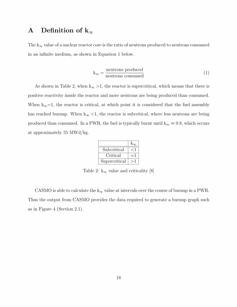
The k∞ value of a nuclear reactor core is the ratio of neutrons produced to neutrons consumed
in an infinite medium, as shown in Equation 1 below.
k∞ =neutrons produced
neutrons consumed(1)
As shown in Table 2, when k∞ >1, the reactor is supercritical, which means that there is
positive reactivity inside the reactor and more neutrons are being produced than consumed.
When k∞=1, the reactor is critical, at which point it is considered that the fuel assembly
has reached burnup. When k∞ <1, the reactor is subcritical, where less neutrons are being
produced than consumed. In a PWR, the fuel is typically burnt until k∞ ≈ 0.8, which occurs
at approximately 55 MWd/kg.
k∞
Subcritical <1Critical =1
Supercritical >1
Table 2: k∞ value and criticality [8]
CASMO is able to calculate the k∞ value at intervals over the course of burnup in a PWR.
Thus the output from CASMO provides the data required to generate a burnup graph such
as in Figure 4 (Section 2.1).
18
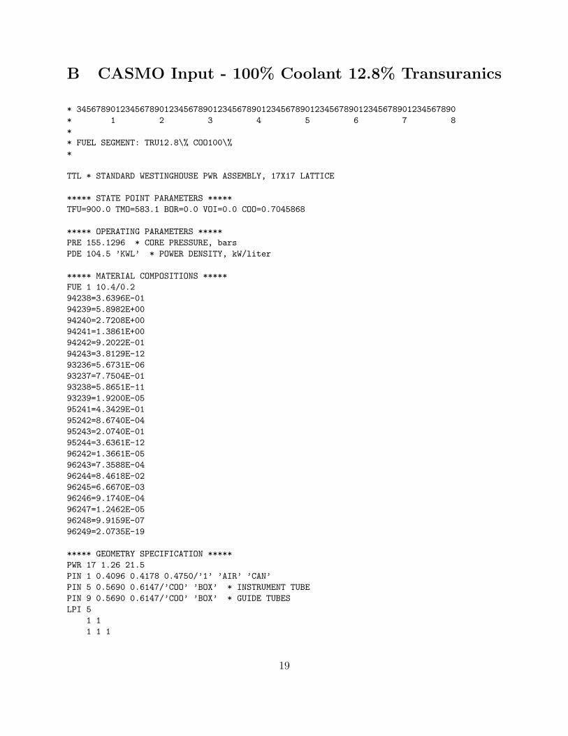
B CASMO Input - 100% Coolant 12.8% Transuranics
* 345678901234567890123456789012345678901234567890123456789012345678901234567890* 1 2 3 4 5 6 7 8** FUEL SEGMENT: TRU12.8\% COO100\%*
TTL * STANDARD WESTINGHOUSE PWR ASSEMBLY, 17X17 LATTICE
***** STATE POINT PARAMETERS *****TFU=900.0 TMO=583.1 BOR=0.0 VOI=0.0 COO=0.7045868
***** OPERATING PARAMETERS *****PRE 155.1296 * CORE PRESSURE, barsPDE 104.5 ’KWL’ * POWER DENSITY, kW/liter
***** MATERIAL COMPOSITIONS *****FUE 1 10.4/0.294238=3.6396E-0194239=5.8982E+0094240=2.7208E+0094241=1.3861E+0094242=9.2022E-0194243=3.8129E-1293236=5.6731E-0693237=7.7504E-0193238=5.8651E-1193239=1.9200E-0595241=4.3429E-0195242=8.6740E-0495243=2.0740E-0195244=3.6361E-1296242=1.3661E-0596243=7.3588E-0496244=8.4618E-0296245=6.6670E-0396246=9.1740E-0496247=1.2462E-0596248=9.9159E-0796249=2.0735E-19
***** GEOMETRY SPECIFICATION *****PWR 17 1.26 21.5PIN 1 0.4096 0.4178 0.4750/’1’ ’AIR’ ’CAN’PIN 5 0.5690 0.6147/’COO’ ’BOX’ * INSTRUMENT TUBEPIN 9 0.5690 0.6147/’COO’ ’BOX’ * GUIDE TUBESLPI 5
1 11 1 1
19

9 1 1 91 1 1 1 11 1 1 1 1 99 1 1 9 1 1 11 1 1 1 1 1 1 11 1 1 1 1 1 1 1 1
DEP -60STAEND
20

C Number Densities of Burnable Nuclides
NUCLIDE NO. DENSITY NUCLIDE NO. DENSITY NUCLIDE NO. DENSITYU-234 3.74637E+18 Cm-243 6.44285E+17 Cs-137 8.35106E+19U-235 2.46544E+19 Cm-244 5.92828E+19 Ba-140 8.74815E+17U-236 5.18691E+18 Cm-245 1.27939E+19 La-140 1.17450E+17U-237 2.04703E+17 Cm-246 1.57390E+18 Nd-143 5.36672E+19U-238 1.90097E+22 Cm-247 5.66576E+16 Nd-145 3.84144E+19U-239 1.03443E+16 Cm-248 6.03319E+15 Pm-147 9.14961E+18Np-236 3.96431E+15 Cm-249 6.52820E+10 Pm-148 4.31155E+16Np-237 8.58113E+19 Bk-249 1.54911E+14 Pm-149 4.90258E+16Np-238 1.36171E+17 Bk-250 7.64317E+10 Sm-147 5.31474E+18Np-239 1.49404E+18 Cf-249 8.78382E+13 Sm-149 5.58727E+17Pu-238 1.75670E+20 Cf-250 5.95003E+13 Sm-150 1.79038E+19Pu-239 7.39147E+20 Cf-251 4.39993E+13 Sm-151 2.88150E+18Pu-240 5.35177E+20 Cf-252 1.91442E+13 Sm-152 8.45609E+18Pu-241 3.10855E+20 Kr-83 3.28292E+18 Eu-153 1.01805E+19Pu-242 2.25470E+20 Rh-103 6.97202E+19 Eu-154 3.96905E+18Pu-243 1.75911E+16 Rh-105 1.03550E+17 Eu-155 6.13069E+17Am-241 5.69648E+19 Ag-109 1.59804E+19 Eu-156 1.90028E+17Am-242 4.94608E+16 I-135 2.23743E+16 Gd155F 3.24192E+16Am-243 6.09316E+19 Xe-131 3.20681E+19 LFP1 1.49070E+21Am-244 3.23096E+16 Xe-135 2.34148E+16 LFP2 4.10857E+20Am242m 1.62515E+18 Cs-133 7.60493E+19Cm-242 1.00986E+19 Cs-134 1.03390E+19
Table 3: Average number densities of burnable nuclides present in the spent modified MOXfuel which initially contained 12.8% transuranics and was burned in a PWR containing 100%coolant/moderator
21

D Wt% of Nuclides
NUCLIDE WT(%) CAPTURE FISSION INT CAPT INT FISS MWD/KGU-234 0.016 6.0833E-04 2.6387E-05 1.6533E+20 7.1748E+18 0.002U-235 0.107 1.1977E-03 3.5206E-03 8.3541E+20 2.3649E+21 0.700U-236 0.023 4.3943E-04 2.1089E-05 1.3528E+20 6.4784E+18 0.002U-238 83.615 1.7422E-01 2.8455E-02 9.2413E+22 1.5441E+22 4.671Pu-238 0.773 1.5675E-02 3.9255E-03 5.8543E+21 1.5777E+21 0.482Pu-239 3.265 1.0675E-01 1.9223E-01 6.4844E+22 1.1778E+23 36.400Pu-240 2.374 1.3845E-01 4.4105E-03 7.4231E+22 2.5506E+21 0.783Pu-241 1.385 3.1368E-02 1.0119E-01 1.5204E+22 4.9709E+22 15.537Pu-242 1.008 2.3518E-02 1.4079E-03 1.1974E+22 7.1201E+20 0.221Am-241 0.254 2.3128E-02 5.4567E-04 1.4640E+22 3.7027E+20 0.116TOT U 83.761 1.7649E-01 3.2024E-02 9.3552E+22 1.7820E+22 5.375TOT PU 8.804 3.1576E-01 3.0316E-01 1.7211E+23 1.7233E+23 53.423FISSILE 4.817 1.4014E-01 3.0208E-01 8.1109E+22 1.7126E+23 53.076FERTILE 87.090 3.3801E-01 3.7639E-02 1.7596E+23 1.9886E+22 6.034
Table 4: Wt% of more prevalent nuclides present in the spent modified MOX fuelwhich initially contained 12.8% transuranics and was burned in a PWR containing 100%coolant/moderator
22

E Change in k∞ over 60 MWd/kg
BURNUP(MWD/KG)
K-INF K-INF M2 PINU-235 (WT%)
FISS PU(WT%)
TOT PU(WT%)
0.000 1.12052 1.12338 55.80 1.091 0.200 7.284 11.2890.100 1.10906 1.11170 55.67 1.090 0.200 7.276 11.2810.500 1.10612 1.10870 55.64 1.089 0.199 7.251 11.2591.000 1.10303 1.10554 55.62 1.089 0.198 7.224 11.2362.000 1.09788 1.10027 55.59 1.089 0.196 7.171 11.1903.000 1.09366 1.09596 55.56 1.088 0.194 7.118 11.1444.000 1.09004 1.09224 55.55 1.088 0.192 7.065 11.0995.000 1.08678 1.08891 55.54 1.087 0.191 7.013 11.0556.000 1.08375 1.08581 55.53 1.087 0.189 6.962 11.0117.000 1.08088 1.08286 55.52 1.086 0.187 6.910 10.9678.000 1.07810 1.08001 55.52 1.086 0.185 6.859 10.9249.000 1.07540 1.07725 55.51 1.085 0.183 6.809 10.88110.000 1.07276 1.07454 55.51 1.085 0.181 6.759 10.83911.000 1.07017 1.07189 55.51 1.084 0.180 6.709 10.79612.500 1.06636 1.06798 55.50 1.084 0.177 6.635 10.73315.000 1.06016 1.06162 55.50 1.082 0.173 6.513 10.62717.500 1.05406 1.05538 55.50 1.081 0.168 6.393 10.52320.000 1.04807 1.04924 55.50 1.080 0.164 6.275 10.41922.500 1.04217 1.04320 55.50 1.079 0.160 6.159 10.31525.000 1.03637 1.03724 55.50 1.077 0.156 6.046 10.21227.500 1.03063 1.03137 55.50 1.076 0.152 5.934 10.11030.000 1.02498 1.02558 55.51 1.075 0.148 5.824 10.00832.500 1.01941 1.01988 55.51 1.074 0.144 5.716 9.90635.000 1.01392 1.01425 55.52 1.072 0.140 5.610 9.80437.500 1.00846 1.00866 55.52 1.071 0.137 5.506 9.70340.000 1.00308 1.00315 55.53 1.069 0.133 5.403 9.60242.500 0.99777 0.99771 55.54 1.068 0.130 5.303 9.50145.000 0.99251 0.99234 55.55 1.067 0.126 5.204 9.40147.500 0.98731 0.98701 55.56 1.065 0.123 5.107 9.30150.000 0.98216 0.98174 55.57 1.063 0.120 5.012 9.20152.500 0.97706 0.97652 55.58 1.062 0.116 4.919 9.10155.000 0.97201 0.97135 55.59 1.061 0.113 4.827 9.00257.500 0.96701 0.96624 55.61 1.059 0.110 4.737 8.90360.000 0.96208 0.96120 55.62 1.058 0.107 4.649 8.804
Table 5: k∞=1 at 40 MWd/kg when the modified MOX fuel, containing 12.8% transuranics,is burned in a PWR containing 100% coolant/moderator
23

F MCNP Input
1/8th Full Assembly model of PWR solid fuelc 17x17 Lattice with 12.8\% TRUscc Bo Feng July 1st, 2008cc 345678901234567890123456789012345678901234567890123456789012345678901234567890c 1 2 3 4 5 6 7 8c cell specificationcc no. mt density surf orient. geometry
1 1 -10.4 -11 vol=5.270718 u=1 imp:n=1 \$ fuel pellet2 2 3.76497e-5 11 -12 u=1 imp:n=1 \$ air gap3 3 4.34384e-2 12 -13 u=1 imp:n=1 \$ clad4 4 -0.704555 13 u=1 imp:n=1 \$ water5 4 -0.704555 -21 u=2 imp:n=1 \$ water/control rod6 3 4.34384e-2 21 -22 u=2 imp:n=1 \$ guide tube7 4 -0.704555 22 u=2 imp:n=1 \$ water8 4 -0.704555 -21 u=3 imp:n=1 \$ water rod9 3 4.34384e-2 21 -22 u=3 imp:n=1 \$ guide tube10 4 -0.704555 22 u=3 imp:n=1 \$ water
101 0 -31 32 -33 34 imp:n=1 u=5 lat=1 fill=-8:8 -8:8 0:01 1 1 1 1 1 1 1 1 1 1 1 1 1 1 1 11 1 1 1 1 1 1 1 1 1 1 1 1 1 1 1 11 1 1 1 1 2 1 1 2 1 1 2 1 1 1 1 11 1 1 2 1 1 1 1 1 1 1 1 1 2 1 1 11 1 1 1 1 1 1 1 1 1 1 1 1 1 1 1 11 1 2 1 1 2 1 1 2 1 1 2 1 1 2 1 11 1 1 1 1 1 1 1 1 1 1 1 1 1 1 1 11 1 1 1 1 1 1 1 1 1 1 1 1 1 1 1 11 1 2 1 1 2 1 1 3 1 1 2 1 1 2 1 11 1 1 1 1 1 1 1 1 1 1 1 1 1 1 1 11 1 1 1 1 1 1 1 1 1 1 1 1 1 1 1 11 1 2 1 1 2 1 1 2 1 1 2 1 1 2 1 11 1 1 1 1 1 1 1 1 1 1 1 1 1 1 1 11 1 1 2 1 1 1 1 1 1 1 1 1 2 1 1 11 1 1 1 1 2 1 1 2 1 1 2 1 1 1 1 11 1 1 1 1 1 1 1 1 1 1 1 1 1 1 1 11 1 1 1 1 1 1 1 1 1 1 1 1 1 1 1 1
111 4 -0.704555 -41 42 -43 44 u=10 fill=5 imp:n=1 \$ assembly112 4 -0.704555 41:-42:43:-44 u=10 imp:n=1 \$ interassembly coolant131 4 -0.704555 -51 52 -53 54 u=11 lat=1 fill=10 imp:n=1 \$ assembly141 4 -0.704555 61 62 63 -64 -65 fill=11 imp:n=1 \$ 1/8 slice200 0 -61:-62:-63:64:65 imp:n=0 \$ outsidec end of cell specification LEAVE BLANK
c surface specificationcc no. shape parameter
24

11 cz 0.4096 \$ fuel radius12 cz 0.4178 \$ clad inner radius13 cz 0.4750 \$ clad outer radius21 cz 0.5690 \$ guide tube inner radius22 cz 0.6147 \$ guide tube outer radius31 px 0.63 \$ pin pitch / 232 px -0.63 \$ -pin pitch / 233 py 0.63 \$ pin pitch / 234 py -0.63 \$ pin pitch / 241 px 10.71 \$ assembly width / 242 px -10.71 \$ assembly width / 243 py 10.71 \$ assembly width / 244 py -10.71 \$ assembly width / 251 px 10.75 \$ assembly pitch/ 252 px -10.75 \$ assembly pitch / 253 py 10.75 \$ assembly pitch / 254 py -10.75 \$ assembly pitch / 2
*61 p 1 -1 0 0 \$ reflective diagonal*62 py 0 \$ reflective x-axis*63 pz -5 \$ reflective bottom*64 pz 5 \$ reflective top*65 px 10.750001 \$ reflective x-valuec end of surface specification LEAVE BLANK
c data specificationc Tally cardscfc64 Flux spectrum - constant lethargy (u=0.1) Paul Romanoe64 1.00E-11 2.00E-11 5.00E-11 1.00E-10 2.00E-10 5.00E-10
6.87E-10 7.60E-10 8.40E-10 9.28E-101.03E-09 1.13E-09 1.25E-09 1.38E-09 1.53E-09 1.69E-091.87E-09 2.07E-09 2.28E-09 2.52E-09 2.79E-09 3.08E-093.41E-09 3.76E-09 4.16E-09 4.60E-09 5.08E-09 5.61E-096.20E-09 6.86E-09 7.58E-09 8.37E-09 9.26E-09 1.02E-081.13E-08 1.25E-08 1.38E-08 1.53E-08 1.69E-08 1.86E-082.06E-08 2.28E-08 2.52E-08 2.78E-08 3.07E-08 3.40E-083.75E-08 4.15E-08 4.58E-08 5.07E-08 5.60E-08 6.19E-086.84E-08 7.56E-08 8.35E-08 9.23E-08 1.02E-07 1.13E-071.25E-07 1.38E-07 1.52E-07 1.68E-07 1.86E-07 2.05E-072.27E-07 2.51E-07 2.77E-07 3.07E-07 3.39E-07 3.74E-074.14E-07 4.57E-07 5.05E-07 5.59E-07 6.17E-07 6.82E-077.54E-07 8.33E-07 9.21E-07 1.02E-06 1.13E-06 1.24E-061.37E-06 1.52E-06 1.68E-06 1.85E-06 2.05E-06 2.27E-062.50E-06 2.77E-06 3.06E-06 3.38E-06 3.73E-06 4.13E-064.56E-06 5.04E-06 5.57E-06 6.16E-06 6.80E-06 7.52E-068.31E-06 9.18E-06 1.02E-05 1.12E-05 1.24E-05 1.37E-051.51E-05 1.67E-05 1.85E-05 2.04E-05 2.26E-05 2.50E-052.76E-05 3.05E-05 3.37E-05 3.72E-05 4.12E-05 4.55E-055.03E-05 5.56E-05 6.14E-05 6.79E-05 7.50E-05 8.29E-059.16E-05 1.01E-04 1.12E-04 1.24E-04 1.37E-04 1.51E-041.67E-04 1.85E-04 2.04E-04 2.25E-04 2.49E-04 2.75E-04
25

3.04E-04 3.36E-04 3.72E-04 4.11E-04 4.54E-04 5.01E-045.54E-04 6.12E-04 6.77E-04 7.48E-04 8.27E-04 9.14E-041.01E-03 1.12E-03 1.23E-03 1.36E-03 1.51E-03 1.67E-031.84E-03 2.03E-03 2.25E-03 2.48E-03 2.75E-03 3.03E-033.35E-03 3.71E-03 4.10E-03 4.53E-03 5.00E-03 5.53E-036.11E-03 6.75E-03 7.46E-03 8.25E-03 9.11E-03 1.01E-021.11E-02 1.23E-02 1.36E-02 1.50E-02 1.66E-02 1.84E-022.03E-02 2.24E-02 2.48E-02 2.74E-02 3.03E-02 3.34E-023.70E-02 4.08E-02 4.51E-02 4.99E-02 5.51E-02 6.09E-026.73E-02 7.44E-02 8.22E-02 9.09E-02 1.01E-01 1.11E-011.23E-01 1.36E-01 1.50E-01 1.66E-01 1.83E-01 2.02E-012.24E-01 2.47E-01 2.73E-01 3.02E-01 3.34E-01 3.69E-014.07E-01 4.50E-01 4.98E-01 5.50E-01 6.08E-01 6.72E-017.42E-01 8.20E-01 9.07E-01 1.00E+00 1.11E+00 1.22E+001.35E+00 1.50E+00 1.65E+00 1.83E+00 2.02E+00 2.23E+002.46E+00 2.72E+00 3.01E+00 3.33E+00 3.68E+00 4.06E+004.49E+00 4.96E+00 5.48E+00 6.06E+00 6.70E+00 7.40E+008.18E+00 9.04E+00 1.00E+01 1.11E+01 1.22E+01 1.35E+011.49E+01 1.65E+01 1.82E+01 2.00E+01 T
f64:n 1 Tcc material specificationcc LEAVE at least 5 spaces before material IDc (10.4 g/cc)m1 8016.60c -1.1850E+01
92234.42c -1.6000E-0392235.52c -2.0000E-0192238.52c -8.6999E+0194238.42c -3.6396E-0194239.14c -5.8982E+0094240.42c -2.7208E+0094241.42c -1.3861E+0094242.42c -9.2022E-0194243.42c -3.8129E-1293236.42c -5.6731E-0693237.42c -7.7504E-0193238.42c -5.8651E-1193239.60c -1.9200E-0595241.42c -4.3429E-0195242.42c -8.6740E-0495243.42c -2.0740E-0196242.42c -1.3661E-0596243.42c -7.3588E-0496244.42c -8.4618E-0296245.42c -6.6670E-0396246.42c -9.1740E-0496247.42c -1.2462E-0596248.42c -9.9159E-07
cc AIR (gap)
26

m2 8016.60c 3.76497E-05cc Zircaloy-4 (6.550g/cc)m3 8016.60c 3.08257e-4
24000.50c 7.58604e-526000.55c 1.48326e-440000.60c 4.24242e-250000.35c 4.81797e-4
cc H2O (15.5MPa at 583.1K) (0.705g/cc)m4 8016.60c 2.35652e-2
1001.60c 4.71033e-2cc initial sourceksrc 2.5 1.3 0.0
10.1 1.3 0.010.1 8.8 0.06.3 5.0 0.0
ccmode nkcode 3000 1.0 20 320prdmp 320 320 320print
27