optical amplifiers - linköping university · zsemiconductor optical amplifiers ... noise figure of...
TRANSCRIPT

Monday, March 14, 2005 Electronic Devices
Optical AmplifiersOptical Amplifiers
Martin HanssonMartin HanssonElectronic Devices, Dept. of Electrical Electronic Devices, Dept. of Electrical
Engineering, LinkEngineering, Linkööping University, Swedenping University, Sweden

Monday, March 14, 2005
2(30)
OutlineOutlineBackgroundBackgroundSemiconductor Optical AmplifiersSemiconductor Optical Amplifiers–– Principles of silicon optical amplifier Principles of silicon optical amplifier -- SOASOA–– GainGain–– NoiseNoise–– Dynamic behaviorDynamic behavior–– Gain clampingGain clamping
Fiber Optical AmplifiersFiber Optical Amplifiers–– Erbium doped fiber amplifiers Erbium doped fiber amplifiers –– EDFAEDFA–– GainGain–– NoiseNoise–– Other propertiesOther properties–– More on pumpingMore on pumping
SummarySummary

Monday, March 14, 2005
3(30)
Background Background -- Optical AmplifiersOptical AmplifiersAmplification in optical transmission systems needed to Amplification in optical transmission systems needed to maintain SNR and BER, despite lowmaintain SNR and BER, despite low--loss in fibers.loss in fibers.
Early optical regeneration for optic transmission relied on Early optical regeneration for optic transmission relied on optical to electron transformation.optical to electron transformation.
AllAll--optical amplifiers provide optical gain without any signal optical amplifiers provide optical gain without any signal conversion to the electron domain.conversion to the electron domain.
Higher bandwidth demands further emphasize the need for Higher bandwidth demands further emphasize the need for allall--optical amplifiers.optical amplifiers.
Two types of allTwo types of all--optical amplifiers:optical amplifiers:
–– Semiconductor optical amplifiers Semiconductor optical amplifiers
–– FiberFiber--optical amplifiers.optical amplifiers.

Monday, March 14, 2005
4(30)
Semiconductor Optical AmplifiersSemiconductor Optical AmplifiersThe semiconductor optical amplifier (SOA) provide optical The semiconductor optical amplifier (SOA) provide optical gain without opticalgain without optical--toto--electronic conversions.electronic conversions.
SOASOA’’ss are typically used in the following ways:are typically used in the following ways:
•• Used as power boosters following Used as power boosters following the source (optical PA).the source (optical PA).
•• Provide optical amplification for Provide optical amplification for longlong--distance communications (indistance communications (in--line amplification, repeaters).line amplification, repeaters).
•• PrePre--amplifiers before the photo amplifiers before the photo detector.detector.
•• AllAll--optical signal processing.optical signal processing.

Monday, March 14, 2005
5(30)
Semiconductor Optical AmplifiersSemiconductor Optical AmplifiersSOASOA’’ss are based on semiconductor lasers.are based on semiconductor lasers.Optical feedback of the laser is reduced.Optical feedback of the laser is reduced.Divided into two sub categories:Divided into two sub categories:–– FabryFabry--Perot Amplifiers (FPA)Perot Amplifiers (FPA)–– Traveling Wave Amplifiers (TWA)Traveling Wave Amplifiers (TWA)
The distinctions depends on the amount of light reflected The distinctions depends on the amount of light reflected back into the cavity.back into the cavity.–– FPAFPA’’ss usually has considerable amount of reflections back to the usually has considerable amount of reflections back to the
cavity cavity –– reflectivity around 0.3, narrow bandwidth (~0.1 nm with a reflectivity around 0.3, narrow bandwidth (~0.1 nm with a carrier at 1550 nm).carrier at 1550 nm).
–– TWATWA’’ss are designed to get as close to a single pass amplification are designed to get as close to a single pass amplification as possible as possible –– reflectivity below 10reflectivity below 10--33, large bandwidth (>30 nm)., large bandwidth (>30 nm).
Monday, March 14, 2005
6(30)
Principle of SOAPrinciple of SOA
Eg,active < Eg,cladding
ncladding < nactive
p+ cladding n+ claddingn active
EF
Eg,cladding
Eg,cladding
Eg,active
electrons
holes
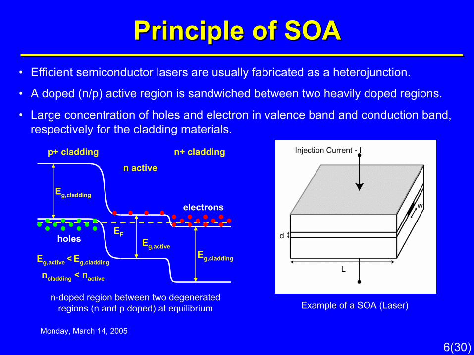
• Efficient semiconductor lasers are usually fabricated as a heterojunction.
• A doped (n/p) active region is sandwiched between two heavily doped regions.
• Large concentration of holes and electron in valence band and conduction band, respectively for the cladding materials.
n-doped region between two degenerated regions (n and p doped) at equilibrium Example of a SOA (Laser)

Monday, March 14, 2005
7(30)
Principle of SOAPrinciple of SOA• A high forward bias applied to the
junction bends the energy bands.
• Holes in the p+ cladding injected inthe active region and the larger band gap of the n+ cladding confines the holes in the active region.
• The higher refractive index in the active region acts as a wave guide for the emitted light.
• A laser uses highly reflective facets of the cavity thus applying a positive feedback to the system.
• In an optical amplifier we are only interested of the gain in a single pass thought the amplifier.
p+ cladding n+ claddingn activeElectron
flow
Hole flow
Vbias
Optical mode
Refractive index profile
Confinement factor Γ
p+ cladding n+ claddingn active

Monday, March 14, 2005
8(30)
Gain of a SOAGain of a SOAAmplification in a SOA Amplification in a SOA -- excited electrons in the active region are excited electrons in the active region are stimulated to recombine with the holes and releasing the excess stimulated to recombine with the holes and releasing the excess energy as identical photons.energy as identical photons.
(1) )()( phg NNgvNRedJ
dtdN
−−=
The rate of excited electrons (N) and the number of photons (Nph) is given by:
J – injection current density
vg – group velocity of light traveling in the amplifier
R(N) – recombination rate
(2) )()( 0NNV
Ng g −Γ
=σ
G(N) is a material gain coefficient:
Γ – optical confinements factor
σg – differential gain
V=Ldw – volume of active region
N0 – carrier density needed for transparency.

Monday, March 14, 2005
9(30)
Gain of a SOAGain of a SOA
(3) 11
)( 0
,
0
satsatph
ph
II
g
NNgNg
+=
+=
(4) 00
−
Γ= N
edJ
Vg s
g τσ
(5) 2sg
satLdwhIτσ
νΓ
=
(6) )( α−Γ= Ngg
( ) (7) )1
(exp 0
−
+Γ= L
IIgG
sats α
Steady state solution of (1) gives:
Where g0 is the small-signal gain given by (4) and Isat by (5).
Net gain per unit length is given by (6).
The single-pass gain through the amplifier is given by integrating over the whole length.
Single-pass gain Gs is given by (7).
α is the total loss coefficient per unit length.

Monday, March 14, 2005
10(30)
Gain saturation in a SOAGain saturation in a SOAThe gain of a SOA will saturate if the optic input power is too The gain of a SOA will saturate if the optic input power is too large.large.
The high input power will consume many of the The high input power will consume many of the EHPEHP’’ss in the in the active region. active region.
The electrons and holes in the cladding regions of the SOA The electrons and holes in the cladding regions of the SOA needs some finite time to reneeds some finite time to re--occupy the active region.occupy the active region.
Saturation of the gain is referred to as the output power for Saturation of the gain is referred to as the output power for which the gain has compressed 3 dB.which the gain has compressed 3 dB.

Monday, March 14, 2005
11(30)
Gain saturation in a SOAGain saturation in a SOA
(8) /
2ln3 dNdG
AhP odB Γ
=τ
ην
Gain compression:
A - active strip, cross section area
ηo – output coupling efficiency
τ – carrier lifetime
Γ– confinement factor
dG/dN – differential gain
hν – photon energy
3dB
Output Power (dBm)
Fibe
r-to-
fiber
Gai
n (d
B)

Monday, March 14, 2005
12(30)
Gain RippleGain RippleUse a antiUse a anti--reflective layer on the facets of the laser cavity to reflective layer on the facets of the laser cavity to reduce the positive feedback .reduce the positive feedback .Ideal antiIdeal anti--reflective layers hard to obtain.reflective layers hard to obtain.Results in ripple in the gain due to the different modes of Results in ripple in the gain due to the different modes of the laser cavity.the laser cavity.Amount of ripple depends on gain and reflectivity.Amount of ripple depends on gain and reflectivity.
(9) )1()1(
2
2
GRGRRipple
−+
=
G – Gain of amplifier
R – Facet reflectivity

Monday, March 14, 2005
13(30)
Methods reducing the rippleMethods reducing the ripplePlace the wave guide at an angle to the facet.Place the wave guide at an angle to the facet.End the wave guide before the facet (window region).End the wave guide before the facet (window region).Using a combination of all three methods can result in R < 10Using a combination of all three methods can result in R < 10--55
p+ cl
addin
g
n+ cl
addin
g
n acti
ve
Residual reflections are not directly reflected back to the cavity
p+ cladding
Light starts to diverge in the window region. Reflections are not reflected
back to the cavity.
n+ cladding
n active
window region

Monday, March 14, 2005
14(30)
Polarization Dependent GainPolarization Dependent GainActive region without symmetry causes light with different Active region without symmetry causes light with different polarization to be amplified differently.polarization to be amplified differently.A difference in gain between TE and TM mode of the A difference in gain between TE and TM mode of the transmitted light can be as high as tens of dB without transmitted light can be as high as tens of dB without countermeasures.countermeasures.Some tactics to reduce the PDG:Some tactics to reduce the PDG:–– Restore symmetry of the active region.Restore symmetry of the active region.
•• Hard to control in industrial processes because active region neHard to control in industrial processes because active region needs to eds to be small for single mode.be small for single mode.
–– Introduce a tensile strain of a laser cavity that emits TE polarIntroduce a tensile strain of a laser cavity that emits TE polarized ized light. light.
•• The cavity starts emitting TM polarized light.The cavity starts emitting TM polarized light.•• Strain can be carefully controlled.Strain can be carefully controlled.
Applied Force
Emitted light

Monday, March 14, 2005
15(30)
Noise in a SOANoise in a SOAStimulated emission is not solely responsible for the light Stimulated emission is not solely responsible for the light amplification in the SOA.amplification in the SOA.
Spontaneous recombination of Spontaneous recombination of EHPEHP’’ss will also be amplified will also be amplified (amplified spontaneous emission).(amplified spontaneous emission).
(10) 2
i
spnNFη
=
Noise figure of an semiconductor optical amplifier (NF)
where (11) 12
2
NNNnsp −
=
N1 and N2 is the number of carriers in ground and excited states, respectively.
ηi is the input coupling loss. Typical ASE spectrum of a SOA.

Monday, March 14, 2005
16(30)
Effects at dynamic operationEffects at dynamic operationLarge input signal to amplified in a SOA compress the gain. Large input signal to amplified in a SOA compress the gain. For WDM systems the gain compression will cause interFor WDM systems the gain compression will cause inter--channel crosstalk.channel crosstalk.–– A large input will compress the gain, limiting the available A large input will compress the gain, limiting the available EHPEHP’’ss
used for amplification of the other channelsused for amplification of the other channels
The gain compression can be used in allThe gain compression can be used in all--optical signal optical signal processing applications.processing applications.–– Wavelength conversion.Wavelength conversion.–– CrossCross--gain modulation.gain modulation.–– CrossCross--phase modulation.phase modulation.
Fast dynamic response of a SOA.

Monday, March 14, 2005
17(30)
Gain clampingGain clampingGain clamping is used to reduce the interGain clamping is used to reduce the inter--channel crosstalk channel crosstalk for WDM systems.for WDM systems.Use distributed Bragg reflectors (DBR) on the facets of the Use distributed Bragg reflectors (DBR) on the facets of the cavity of the amplifier.cavity of the amplifier.Wavelength selective feedback in the cavity. Wavelength selective feedback in the cavity. Laser mode created at a wavelength outside of the Laser mode created at a wavelength outside of the interesting amplification band.interesting amplification band.

Monday, March 14, 2005
18(30)
Gain clampingGain clampingA gain clamped SOA has a gainA gain clamped SOA has a gain--vs.vs.--output power that is output power that is constant over a large power range.constant over a large power range.The laser power is used as a reservoir of optical energy The laser power is used as a reservoir of optical energy which removes the gain compression.which removes the gain compression.When the laser energy is consumed laser action turns off.When the laser energy is consumed laser action turns off.Amplifier saturates very fast.Amplifier saturates very fast.

Monday, March 14, 2005
19(30)
Fiber Optical AmplifiersFiber Optical AmplifiersFiber optical amplifiers are based on rareFiber optical amplifiers are based on rare--earthearth--doped doped fibers.fibers.Amplification is obtained at different wavelength depending Amplification is obtained at different wavelength depending on which rareon which rare--earthearth--ions that is used.ions that is used.Most commonly used is Erbium (Most commonly used is Erbium (ErEr) with atomic number 68, ) with atomic number 68, placed among a placed among a LanthanidesLanthanides in the periodic system.in the periodic system.SilicaSilica--fibers doped with fibers doped with ErEr ions can obtain high gain at a ions can obtain high gain at a wavelength of 1550 nm.wavelength of 1550 nm.
Fiber optic amplifiers can be used as:Fiber optic amplifiers can be used as:–– Power amplifiersPower amplifiers–– Repeaters, inRepeaters, in--line amplifiersline amplifiers–– PrePre--amplifiersamplifiers

Monday, March 14, 2005
20(30)
Erbium Doped Fiber AmplifierErbium Doped Fiber AmplifierAn ErbiumAn Erbium--ion doped fiber pumped with light of certain ion doped fiber pumped with light of certain wavelengths. wavelengths. Erbium ions are excited to any of their excited states.Erbium ions are excited to any of their excited states.Most common pump wavelengths used are 980 nm and 1480 nm.Most common pump wavelengths used are 980 nm and 1480 nm.Excites the ErbiumExcites the Erbium--ions to the second and first excited energy ions to the second and first excited energy level, respectively.level, respectively.
Electrons in the Electrons in the 44II11/211/2 energy level leaves energy level leaves that energy level for that energy level for 44II13/213/2 with a spontaneous with a spontaneous life time of life time of ττ3232..
The transition between The transition between 44II11/211/2 and and 44II13/2 13/2 are a are a nonnon--radiativeradiative transition that emits a quantum transition that emits a quantum vibration to the crystal lattice (vibration to the crystal lattice (phononphonon). ).
Light with wavelength between 1520 nm and Light with wavelength between 1520 nm and 1570 nm induce stimulated emission in the 1570 nm induce stimulated emission in the ErEr--ions.ions.
980nm 1480nm1520 –
1570 nm
Er3+
4I15/2
4I13/2
4I11/2τ32 ~ 1 µs
τsp ~ 10 ms

Monday, March 14, 2005
21(30)
Erbium Doped Fiber AmplifierErbium Doped Fiber Amplifier
General Erbium-doped fiber configuration
A basic EDFA setup includes optical isolators, wavelength A basic EDFA setup includes optical isolators, wavelength selective couplers, pump lasers, and the fiber itself.selective couplers, pump lasers, and the fiber itself.Fiber can be pumped with light that either coFiber can be pumped with light that either co-- or counteror counter--propagates with the amplified light, or both.propagates with the amplified light, or both.The optical isolators are used to limit the ASE and any lasing The optical isolators are used to limit the ASE and any lasing modes in the fiber.modes in the fiber.

Monday, March 14, 2005
22(30)
Gain in Gain in EDFAEDFA’’ss
(15) )()((14) )()(*
(13) )()()()(*
),(),(
1),(
(12) ),()(
12
0
λσλαλσλ
λαλ
λλ
λ
λλ
aErs
eErs
L
in
out
nng
zNzNgdzzdP
zPzg
dzzgPPG
Γ=
Γ=
−=
==
⋅== ∫
The amplification in a EDFA is supplied when incoming light The amplification in a EDFA is supplied when incoming light stimulates the stimulates the ErEr--ions to return to the ground state and emitting ions to return to the ground state and emitting the excessive energy as coherent light.the excessive energy as coherent light.
Gain in the EDFA is defined as (12) where g(λ,z) is the gain coefficient over the length of the ED fiber according to (13).
The emission coefficient and absorption coefficient are given by (14) and (15) respectively.
Γs is the confinement factor of the fiber, nEr is the concentration of Er-ions in the core, σe and σa are the signal emission and absorption cross sections as functions of wavelength.

Monday, March 14, 2005
23(30)
Gain in Gain in EDFAEDFA’’ssThe gain spectrum of a EDFA is not flat over a wide The gain spectrum of a EDFA is not flat over a wide wavelength range.wavelength range.Gain coefficient depends highly on the inversion of the Gain coefficient depends highly on the inversion of the fiber.fiber.
• 100 % inversion – all ions excited to first excited energy state or higher.
• -100 % inversion – non of the ions excited and incoming light is absorbed.

Monday, March 14, 2005
24(30)
Gain saturationGain saturationGain saturation occurs when the stimulated emission is Gain saturation occurs when the stimulated emission is balanced by the absorption of pump energy.balanced by the absorption of pump energy.The higher the pump power the more excited The higher the pump power the more excited ErEr--ions and ions and the higher saturation power.the higher saturation power.PPsatsat defined as the power where the gain coefficient is defined as the power where the gain coefficient is reduced by half.reduced by half.
( ) (16) 1
+
Γ+= th
pes
pas
spsases
cssat P
PAhPσσ
τσσν
Where σes and σas are the emission and absorption cross sections, respectively, at the signal wavelength
Ac is the core are area, τsp is the spontaneous lifetime of the first excited state of the Er-ions, and Pp is the pump power.
The pump threshold for transparency is given by (17).
Below the pump threshold the gain coefficient is negative, because there are several non-excited ions in the fiber that absorbs the incoming signal.
(17) apspp
cs
es
asthp
AhPστ
νσσ
Γ=
Where hνp is the pump photon energy, Γp is the confinement factor of the pump mode and σap is the pump absorption cross section.
Monday, March 14, 2005
25(30)
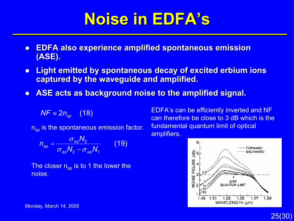
Noise in Noise in EDFAEDFA’’ssEDFA also experience amplified spontaneous emission EDFA also experience amplified spontaneous emission (ASE).(ASE).Light emitted by spontaneous decay of excited erbium ions Light emitted by spontaneous decay of excited erbium ions captured by the waveguide and amplified.captured by the waveguide and amplified.ASE acts as background noise to the amplified signal.ASE acts as background noise to the amplified signal.
(18) 2 spnNF ≈
(19) 12
2
NNNn
ases
essp σσ
σ−
=
nsp is the spontaneous emission factor.
EDFA’s can be efficiently inverted and NF can therefore be close to 3 dB which is the fundamental quantum limit of optical amplifiers.
The closer nsp is to 1 the lower the noise.

Monday, March 14, 2005
26(30)
Coupling LossCoupling LossMismatch between the Mismatch between the ErEr--doped fiber modes and doped fiber modes and transmission fiber modes.transmission fiber modes.
ErEr--doped fibers usually 2doped fibers usually 2--4 4 µµm in diameter m in diameter –– ordinary ordinary transmission fiber have a diameter of 8transmission fiber have a diameter of 8--10 10 µµm.m.
Direct ButtDirect Butt--coupling would have coupling loss of several coupling would have coupling loss of several dB.dB.
Fusion splice is used to couple the fibers.Fusion splice is used to couple the fibers.
Doping in splice region can be controlled so that a Doping in splice region can be controlled so that a optimized lowoptimized low--loss tapered region is formed.loss tapered region is formed.
Total input and output coupling noise of a EDFA fiber using Total input and output coupling noise of a EDFA fiber using spliced fusion regions is usually less than 1.5 dB.spliced fusion regions is usually less than 1.5 dB.

Monday, March 14, 2005
27(30)
PolarizationPolarizationBecause of the symmetric core of the Because of the symmetric core of the ErEr--doped fiber, the doped fiber, the gain is virtually independent of polarization.gain is virtually independent of polarization.
One of the main advantages of One of the main advantages of EDFAEDFA’’ss compared to compared to SOASOA’’ss..
Small polarization dependence by different polarization of Small polarization dependence by different polarization of ions in fiber.ions in fiber.

Monday, March 14, 2005
28(30)
More on pumpingMore on pumpingWhy is the two pump wavelengths of 980 nm and 1480 nm Why is the two pump wavelengths of 980 nm and 1480 nm chosen?chosen?The ErThe Er3+3+ ions next four excited energy levels corresponds ions next four excited energy levels corresponds to pumping wavelengths of 514 nm, 532 nm, 667 nm, and to pumping wavelengths of 514 nm, 532 nm, 667 nm, and 800 nm. 800 nm. Why not use any of these wavelengths?Why not use any of these wavelengths?

Monday, March 14, 2005
29(30)
More on pumpingMore on pumpingPump light of any of the six specific wavelength will excite Pump light of any of the six specific wavelength will excite the the ErEr--ions to the corresponding energy level.ions to the corresponding energy level.The ions decays The ions decays nonradiativelynonradiatively down to the first excited down to the first excited state.state.Laser diodes developed for 665 nm and 800 nm Laser diodes developed for 665 nm and 800 nm -- could be could be used for pumping used for pumping ErEr--doped fibers.doped fibers.Pump efficiency for shorter wavelengths is lowered due to Pump efficiency for shorter wavelengths is lowered due to excited state absorption (ESA)excited state absorption (ESA)ESA ESA -- pump light excites pump light excites ErEr--ions at the first excited state to ions at the first excited state to higher stateshigher statesAbsorbs the pump light and thus reduces amplification.Absorbs the pump light and thus reduces amplification.Efficient pumping is achieved at the wavelengths for 980 Efficient pumping is achieved at the wavelengths for 980 nm and 1480 nm, which is way they are chosen.nm and 1480 nm, which is way they are chosen.
Monday, March 14, 2005
30(30)
SummarySummaryOptical amplifiers provide amplification in fiber optic Optical amplifiers provide amplification in fiber optic transmission without transmission without optoopto--electron conversions.electron conversions.
Two types of optical amplifiers Two types of optical amplifiers –– semiconductor optical semiconductor optical amplifiers and fiber optical amplifiers.amplifiers and fiber optical amplifiers.
SOASOA’’ss based on lasers based on lasers –– can be either wide or narrow bandcan be either wide or narrow band
Main application besides amplification Main application besides amplification –– all optical signal all optical signal processing.processing.
EDFAEDFA’’ss provide gain in a fiber by pumping it with laser light provide gain in a fiber by pumping it with laser light –– Optimal for signal wavelength close to 1.55 Optimal for signal wavelength close to 1.55 µµm.m.
Vertically no polarization dependence on the gain.Vertically no polarization dependence on the gain.