operator’s manual - radzim.co.zwradzim.co.zw/downloads/engines/111000000381-001-00.pdf · should...
TRANSCRIPT

OPERATOR’S MANUALGenerating set and industrial engines
13 liter (EMS 2)

CALIFORNIA PROPOSITION 65 WARNING
Engine exhaust, some of its constituents, and a broad range of engine parts are known to the State ofCalifornia to cause cancer, birth defects, and other reproductive harm. Additionally, lubricants, fuels, andother fluids used in engines–including any waste created through the wearing of engine parts–contain orproduce chemicals known to the State of California to cause cancer and birth defects or other reproductiveharm.
Battery posts, terminals, and related accessories contain lead and lead compounds. Wash your hands afterhandling. Used engine oil contains chemicals that have caused cancer in laboratory animals. Alwaysprotect your skin by washing thoroughly with soap and water.

Content
Foreword ...................................................................................................... 2Safety Information ...................................................................................... 3Introduction ................................................................................................. 7Presentation .............................................................................................. 10Instruments and Controls ........................................................................ 11Starting ...................................................................................................... 18Operation ................................................................................................... 22Engine Shutdown ...................................................................................... 23Fault Handling ........................................................................................... 26Fault Code Register .................................................................................. 31Maintenance Schedule ............................................................................. 43Maintenance .............................................................................................. 45Storage ....................................................................................................... 64Technical Data ........................................................................................... 66Operator's Manual Order .......................................................................... 73
Alphabetical index .................................................................................... 75

ForewordVolvo Penta engines are used all over the world. They are used in all possible operating conditions. This is not acoincidence. After 100 years as an engine manufacturer the Volvo Penta name has become a symbol of reliability,technical innovation, top of the range performance and long service life. We also believe that this is what youdemand and expect of your Volvo Penta engine.
We would like you to read this operator’s manual thoroughly and consider the advice we give on running andmaintenance. Please pay attention to the safety instructions contained in the manual.
As owner of a Volvo Penta engine, we would also like to welcome you to a worldwide network of dealers andservice workshops to assist you with technical advice, service requirements and replacement parts. Please con-tact your nearest authorized Volvo Penta dealer for assistance.
You will find your closest dealer at our home page on the Internet www.volvopenta.com - amongst otheruseful information about your Volvo Penta engine - we invite you to visit!
2 7748641 06-2010

Safety InformationRead the Operators Manual through very carefully before you start the engine or do any maintenance or service.It has to do with your safety, an incorrect operation can lead to personal injury and damage to products or property.This chapter describes how safety precaution is presented in the Operators Manual and on the product. It alsogives you an introduction to the basic safety rules for using and looking after the engine.If there is still something which is unclear or if you feel unsure about it, please contact your Volvo Penta dealerfor assistance.
NOTICE! Check that you have received the correct operator’s manual before you read on. If not, please contactyour Volvo Penta dealer.
!This symbol is used in the Operators Manual and on the product, to call your attentionto the fact that this is safety information. Always read such information very carefully.Safety texts in the Operators Manual have the following order of priority:
DANGER!Indicates a hazardous situation which, if not avoided, will result in death or seriousinjury.
WARNING!Indicates a hazardous situation which, if not avoided, could result in death or seriouspersonal injury.
CAUTION!Indicates a hazardous situation which, if not avoided, could result in minor or moderatepersonal injury.
IMPORTANT!Indicates a situation which, if not avoided, could result in property damage.
NOTICE! Used to draw your attention to important information that will facilitate thework or operation in progress.
This symbol is used on our products in some cases and refers to important informationin the Operators Manual. Make sure that warning and information symbols on theengine are clearly visible and legible. Replace symbols which have been damaged orpainted over.
7748641 06-2010 3

Safety rules for operation and maintenanceDaily checksMake it a habit to give the engine and engine bay avisual check before starting (before the engine isstarted) and after operation (once the engine hasstopped). This helps you to quickly discover whetherany leakage of fuel, coolant, oil or any other abnormalevent has happened, or is about to happen.
Starting lockIf the instrument panel does not have a key switch,the engine room must be lockable, to prevent unau-thorized persons from starting the engine. Alterna-tively, a lockable main switch can be used.
Carbon monoxide poisoningOnly start the engine in a well ventilated area. Whenoperated in a confined space, exhaust fumes andcrankcase gases must be ventilated.
Hot surfaces and fluidsA hot engine always increases the risk for burns. Beon your guard against hot surfaces: the exhaust mani-fold, turbocharger, oil pan, charge air pipe, startingheater, hot coolant and hot lubricating oil in pipes,hoses etc.
Cooling SystemAvoid opening the coolant filling cap when the engineis hot. Steam or hot coolant can spray out and causescalding, at the same time as the pressure built up islost.If the filler cap, coolant hose etc., still has to be openedor removed when the engine is hot, undo the filler capslowly and carefully, to let the pressure out beforeremoving the filler cap completely and starting work.Note that the coolant can still be hot and cause scald-ing.
Fuel fillingThere is always a risk of fire and explosion during fuelfilling. Smoking is forbidden, and the engine should bestopped.Never overfill the tank. Shut the tank cap securely.Only use the fuel recommended in the OperatorsManual. The wrong grade of fuel can cause malfunc-tions or stop the engine. In a diesel engine, it can alsocause the injection pump to seize and the engine willover-rev, entailing a strong risk of personal injury andmachinery damage.
Fuel and lubrication oilsAlways protect your hands when searching for leaks.Fluids which leak under pressure can force their wayinto body tissue and cause severe injury. There is arisk of blood poisoning (septicemia).Only use the fuel recommended in the OperatorsManual. The wrong grade of fuel can cause malfunc-tions or stop the engine. In a diesel engine, it can alsocause the injection pump to seize and the engine willover-rev, entailing a strong risk of personal injury andmachinery damage.Always cover the alternator if it is located beneath thefuel filters. Fuel spillage can damage the alternator.Always change the oil, oil filter and fuel filter at thespecified intervals.
OperationThe engine must not be operated in environmentswhich contain explosive media since none of the elec-trical and mechanical components are explosionproof.Going close to a running engine is a safety risk. Hair,fingers, loose clothes, or dropped tools can catch onrotating components and cause severe injury.When engines are supplied without touch guards, allrotating components and hot surfaces must be pro-tected after installation in their application, if neces-sary for personal safety.
Safety Information
4 7748641 06-2010

Care and maintenanceKnowledgeThe Operators Manual contains instructions for doingthe most common service and maintenance tasks ina safe and correct manner. Read them carefullybefore starting work.Literature for more major tasks is available from yourVolvo Penta dealer.Never do a job if you are not entirely sure about howto do it. Please contact your Volvo Penta dealer andask for assistance instead.
Before startingRe-install all guards which have been removed duringservice work, before re-starting the engine. Make surethat there are no tools or other objects left behind onthe engine.Never start a turbocharged engine without the air filterin place. The rotating compressor turbine in the tur-bocharger can cause severe injury. There is also arisk that foreign bodies could be sucked in and causedamage to the machinery.
Stopping the engineStop the engine before opening or removing theengine hatch/hood. Service and maintenance workshould be done with the engine stopped unless oth-erwise specified.Prevent the engine from being started by pulling outthe starter key and disconnect the power with themain switch. Lock them in the “Off” position.If the instrument panel does not have a key switch,remove the system voltage with the main switch.Fix a notice by the operator position to say that workis in progress.Working with, or approaching a running engine is asafety risk. Hair, fingers, loose clothes, or droppedtools can catch on rotating components and causesevere injury. Volvo Penta recommends that all serv-ice work which requires the engine to be runningshould be done by an authorized Volvo Penta work-shop.
Lifting the engineThe lifting eyes fitted on the engine should be usedfor lifting. Always check that the lifting devices are ingood condition and that they have the correct capacityfor the lift (engine weight together with auxiliaries, iffitted). The engine should be lifted with an adjustablelifting boom for safe handling. All chains or cablesshould be parallel to each other and should be assquare as possible to the top of the engine. Pleasenote that auxiliary equipment installed on the enginecould change its center of gravity. Special lifting devi-ces may then be needed to obtain the correct balanceand safe handling. Never carry out work on an enginethat is only suspended in a hoist.
Fire and explosionFuel and lubrication oilAll fuel, most lubricants and many chemicals are flam-mable. Always read and observe the advice on thepackages.Work on the fuel system must be done with the enginecold. Fuel leakage and spills on hot surfaces or elec-trical components can cause fires.Store oil and fuel soaked rags and other flammablematerial in a fireproof manner. Oil soaked rags canself-ignite in certain circumstances.Never smoke when filling fuel, lubrication oil or whenclose to fuel filling stations or the engine bay.
BatteriesBatteries contain and give off an explosive gas, espe-cially when charged. This gas is very flammable andhighly explosive.Smoking, open flames or sparks must never occur inor near to batteries or the battery locker.Incorrect connection of a battery cable or start cablecan cause a spark which can be sufficient, in its turn,to make the battery explode.
Spare partsComponents in fuel systems and electrical systemson Volvo Penta engines are designed and manufac-tured to minimize the risk of explosions and fire, inaccordance with applicable legal requirements.The use of spare parts not approved by Volvo Pentacan cause an explosion or fire.
Start sprayNever use start spray or similar preparations to helpin starting an engine with air pre-heating (glow plugs /starting heater). They may cause an explosion in theinlet manifold. Danger of personal injury.
Safety Information
7748641 06-2010 5
Electrical SystemDisconnect the powerBefore any work is done on the electrical system, theengine must be stopped and the power removed byswitching off the main switch(es). Any external powersupply for engine heaters, battery chargers or otherauxiliary equipment connected to the engine must bedisconnected.
BatteriesBatteries contain a highly corrosive electrolyte. Pro-tect your eyes, skin and clothes during charging andother handling of batteries. Always use protectivegoggles and gloves.If acid comes into contact with your skin, wash at oncewith soap and a lot of water.If you get battery acid in your eyes, flush at once witha lot of cold water, and get medical assistance atonce.
Electric weldingRemove the positive and negative cables from thebatteries.Then disconnect all cables connected to the alterna-tor. Disconnect both connectors from the engine con-trol module.Always connect the welder earth clamp to the com-ponent to be welded, and as close as possible to theweld site. The clamp must never be connected to theengine or in such a way that current can pass througha bearing.When welding is completed: Always connect thecables to the alternator and engine control unit con-nector before reconnecting the battery cables.
Safety Information
6 7748641 06-2010

IntroductionThis Operator's Manual refers to the industrial enginesTAD1341GE, TAD1342GE, TAD1343GE,TAD1344GE, TAD1345GE, TAD1350GE,TAD1351GE, TAD1352GE, TAD1353GE,TAD1354GE, TAD1355GE, TAD1340VE,TAD1341VE, TAD1342VE, TAD1343VE,TAD1344VE, and TAD1345VE.They are in-line, six-cylinder, direct injection industrialdiesel engines. All of the engines are equipped withelectronically controlled fuel management (EMS), tur-bocharger, charge air cooler, thermostatically control-led cooling systems and electronic speed control.The Operator's Manual contains the information youneed to be able to operate and maintain your VolvoPenta safely and correctly. Please read the manualcarefully and learn to handle the engine and otherequipment in a safe manner before you start theengine.
NOTICE! The manual describes the engine and equip-ment sold by Volvo Penta. Differences in appearanceand function of the controls and instruments may occurin certain variants. In these cases, please refer to theOperator's Manual for the relevant application.
NOTICE! When ordering service or spares, alwaysindicate the engine and transmission identificationnumber. Refer to Technical Data page 71.
7748641 06-2010 7

WarrantyYour new Volvo Penta industrial engine is covered bya limited warranty, according to the conditions andinstructions compiled in the Warranty and Servicebook.Please note that AB Volvo Penta's liability is limitedas specified in the Warranty and Service Book. Readit carefully, as soon as possible after delivery. It con-tains important information about the warranty card,service intervals and service that the owner must beaware of, check and perform. If this is not done, ABVolvo Penta may disclaim its warranty obligations inpart or in full.Please contact your Volvo Penta dealer if youhave not received a Warranty and Service book,or a customer copy of the warranty card.
Running inThe engine must be “run in” during its first 10hours, as follows:Run the engine in normal operations. However, fullload may not be applied other than for short periods.Never run the engine for an extended period of timeat constant speed during this period: this does notapply to GE engines.Higher oil consumption is normal during the first100-200 hours of operation. For this reason, check theoil level more frequently than normally recommended.When a disengageable clutch is installed, it should bechecked more carefully during the first days. Adjust-ments may be necessary to compensate for beddingin of the friction plates.
Environmental responsibilityAll of us want to live in a clean, healthy environment,where we can breathe clean air, see healthy trees,have clean water in lakes and seas, and be able toenjoy the sunlight without fearing for our health.Unfortunately, this is not a matter of course thesedays, but something we all must work toward.As an engine manufacturer, Volvo Penta has specialresponsibility, and for this reason environmental careis a natural cornerstone of our product development.Volvo Penta currently has a broad engine program inwhich considerable progress has been made inreducing exhaust emissions, fuel consumption andengine noise etc.We hope that you will be keen to preserve these qual-ities. Always follow the advice in the Operator's Man-ual about fuel grades, operation and maintenance, toavoid unnecessary environmental impact. Contactyour Volvo Penta dealer if you notice any changessuch as increased fuel consumption or increasedexhaust smoke.Remember always to hand in hazardous waste suchas drained oil, coolant, old batteries etc. for destruc-tion at a recycling facility.If we unite our efforts, we can make a valuable con-tribution to the environment together.
Maintenance and replacement partsVolvo Penta engines are designed for maximum reli-ability and long life. They are built to withstand ademanding environment, but also to have the smallestpossible environmental impact. These qualities areretained through regular service and use of genuineVolvo Penta parts.Volvo Penta has a world-wide network of authorizeddealers. They are Volvo Penta product specialists,and have the accessories, genuine parts, test equip-ment and special tools needed for high quality serviceand repair work.Always follow the maintenance intervals in themanual, and remember to note the engine/trans-mission identification number when you orderservice and replacement parts.
Introduction
8 7748641 06-2010
Certified EnginesIf you own an emission-certified engine used in anarea where exhaust emissions are regulated bylaw, it is important to be aware of the following:Certification means that an engine type has beenchecked and approved by the relevant authority. Theengine manufacturer guarantees that all engines of thesame type are equivalent to the certified engine.This places special demands on the care and mainte-nance you provide your engine, namely:
• Maintenance and service intervals recommendedby Volvo Penta must be complied with.
• Only genuine Volvo Penta parts may be used.
• Service on injection pumps, pump settings andinjectors must always be done by an authorizedVolvo Penta workshop.
• The engine must not be converted or modified,except with accessories and service kits whichVolvo Penta has developed for the engine.
• No installation changes to the exhaust pipe andengine air inlet ducts may be made.
• No warranty seals (where present on the product)may be broken by unauthorized persons.
The general instructions in the Operator's Manual con-cerning operation, service and maintenance apply.
NOTICE! Neglected or poorly performed care/service,as well as the use of non-genuine spare parts, willmean that AB Volvo Penta no longer can guaranteethat the engine conforms to the certified model.Damages and/or costs arising from this will not becompensated by Volvo Penta.
Introduction
7748641 06-2010 9

Presentation
EMS (Engine ManagementSystem)
EMS (Engine Management System) is an electronic system with CAN communication (Controller Area Network)for diesel engine control. The system has been developed by Volvo Penta and includes fuel control and diagnosticfunctions.The system comprises among other things sensors, a control unit and unit injectors. The sensors send inputsignals to the control unit, which in turn controls the unit injectors.
Diagnostic functionThe purpose of the diagnostic function is to detect andlocalize any malfunctions in the EMS system, to pro-tect the engine and to ensure operation in the eventof serious malfunction.If a malfunction is detected, this is announced bywarning lamps, a flashing diagnostic lamp or in plainlanguage on the instrument panel, depending on theequipment used. If a fault code is obtained as a flash-ing code or in plain language, it is used for guidancein any fault tracing. Fault codes can also be read byVolvo’s VODIA tool at authorized Volvo Penta work-shops.If there is a serious malfunction, the engine will beshut down altogether, or the control unit will reducethe power delivered (depending on application). Onceagain, a fault code is set for guidance in any faulttracing.
Input signalsThe control unit receives input signals about engineoperating conditions etc. from the following compo-nents:
- coolant temperature sensor
- charge pressure / charge temperature sensor
- crankcase pressure sensor
- position sensor, camshaft
- rpm sensor, flywheel
- coolant level sensor
- oil level and temperature sensor
- oil pressure sensor
- fuel pressure sensor
- water-in-fuel indicator
Fuel controlThe engine fuel requirement is analyzed up to 100times per second. The amount of fuel injected into theengine and the injection advance are fully electroni-cally controlled via fuel valves and the unit injectors.This means that the engine always receives the cor-rect volume of fuel in all operating conditions, whichprovides lower fuel consumption, minimal exhaustemissions etc
Output signalsThe control module uses the input signals to controlthe following components:
- unit injectors
- starter motor
- main relay
- pre-heating relay
The information from the sensors provides precisedata about prevailing operating conditions and allowsthe processor in the control module to, among otherthings, calculate correct injection amount, injectiontiming and check the engine's condition.
10 7748641 06-2010

Instruments and Controls
DCU (Display Control Unit)The DCU (Diesel Control System) control panel isavailable as an optional accessory for the EMS(Engine Management System) electronic control sys-tem.The DCU is a digital instrument panel which commu-nicates with the engine control unit. The DCU has sev-eral functions, such as engine control, monitoring,diagnostics, and parameter setting.
The menus in the DCU system can be used to check,and in some cases to set, a number of different func-tions in the EMS system.
NOTICE! The menus and illustrations shown here arethe English version. The language can be changed,however; refer to the Setup menu.
1 2 3 4 5 6
7
8910
P0002062
1 LED display 6 ON/OFF. Starts and stops the system2 START. Starts the engine 7 Scroll downwards in menus3 SPEED - . Reduces engine rpm 8 SEL. Selects in menus4 SPEED +. Increases engine rpm 9 Scroll upwards in menus5 STOP. Stops the engine 10 ESC. Return to previous menu selection
StartWhen the DCU panel is started, the “Engine Data”menu is displayed; press “ESC” to come to the mainmenu.
7748641 06-2010 11
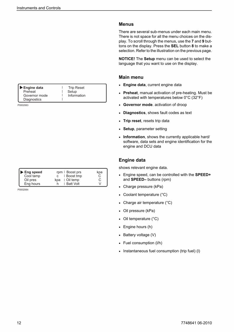
MenusThere are several sub-menus under each main menu.There is not space for all the menu choices on the dis-play. To scroll through the menus, use the 7 and 9 but-tons on the display. Press the SEL button 8 to make aselection. Refer to the illustration on the previous page.
NOTICE! The Setup menu can be used to select thelanguage that you want to use on the display.
Main menu• Engine data, current engine data
• Preheat, manual activation of pre-heating. Must beactivated with temperatures below 0°C (32°F)
• Governor mode. activation of droop
• Diagnostics, shows fault codes as text
• Trip reset, resets trip data
• Setup, parameter setting
• Information, shows the currently applicable hard/software, data sets and engine identification for theengine and DCU data
Engine datashows relevant engine data.
• Engine speed, can be controlled with the SPEED+and SPEED– buttons (rpm)
• Charge pressure (kPa)
• Coolant temperature (°C)
• Charge air temperature (°C)
• Oil pressure (kPa)
• Oil temperature (°C)
• Engine hours (h)
• Battery voltage (V)
• Fuel consumption (l/h)
• Instantaneous fuel consumption (trip fuel) (l)
Instruments and Controls
12 7748641 06-2010

Preheatmanual activation of pre-heating. When it is activated,the EMS system senses at start-up if pre-heating isneeded. For automatic pre-heating, refer to the Setup /Preheat on ignition menu.
NOTICE! Must be activated with temperatures below0°C (32°F).
The pre-heating time is adjusted to suit the enginetemperature, and can last for up to 50 seconds bothbefore and after starting. Refer also to Starting proce-dure EMS.
• Press SEL, the text Preheat requested will beshown
• The display automatically returns to the EngineData menu.
Governor modeactivates/shuts off droop. To set the droop level, referto the Setup / Governor gradient or Governor droopmenu.
• Select Isochronous mode or Droop mode with theSEL button.
Diagnosticsshows the error list containing the 10 latest active andinactive faults. The fault codes are shown as text onthe display.
• Scroll through the fault list with the arrow keys.
Trip Data resetresets trip data, such as fuel consumption.
• Press the SEL button to reset trip data
Instruments and Controls
7748641 06-2010 13

Setupparameter setting in the engine's control systems. Dif-ferent menus appear under Customer parameter,depending on whether Versatile or Gen set has beenselected from Set application. See below.
The parameters that can be set/selected (choice ismade with the SEL button) are:
• Set application, setting Versatile or Gen set.Depending on the selection made here, differentmenus will appear under Customer parameter.
• Unit, setting of units (metric or US imperial).
• Language, setting the language used on the dis-play. Choose between English, French, Germanand Spanish.
• Stop energized to, setting of external stop input.Activated by Stop or Run.Stop: The stop input must be connected to voltageto stop the engine.Run: The stop input must be connected to voltageto run the engine.
• Customer parameter, setting alarm limits. Refer toCustomer parameter / Versatile and Customerparameter / Gen set.
• Throttle input setting, setting of engine-speedcontrol and voltage limits. Refer to Throttle inputsetting.
• Display setting, setting the display. refer to Displaysetting.
Customer parameter / Versatile• Idle engine speed - setting idle speed.
• Preheat on ignition - activation of automatic pre-heating. The engine control system senses if pre-heating is needed and activates it directly at switch-on.
• Governor gradient (Nm/rpm) - setting of drooplevel, when activated. For activation, refer to Gov-ernor droop in the main menu.
• Oil temp warning limit (°C) - setting alarm limit foroil temperature.
• Coolant temp warning limit (°C) - setting alarmlimit for coolant temperature.
Instruments and Controls
14 7748641 06-2010

Customer parameter / Gen set• Primary engine speed - selection of engine rpm,
1500 or 1800 rpm.
• Preheat on ignition - activation of automatic pre-heating. The engine control system senses if pre-heating is needed and activates it directly at switch-on.
• Governor droop (%) - setting of droop level, whenactivated. For activation, refer to “Governor droop”in the main menu.
• Overspeed limit (%) - setting of limit for overspeedalarm, % of set engine rpm.
• Overspeed shutdown - activation of engine shut-down with overspeed alarm. Refer to “Overspeedlimit” to activate the alarm limit for the excess rpmalarm.
• Oil temp warning limit (°C) - setting alarm limit foroil temperature.
• Coolant temp limit (°C) - setting alarm limit forcoolant temperature.
Throttle input settingrpm control setting (throttle operation).
• Set throttle mode - OFF - engine rpm is controlledvia the DCU panel.ext throttle input - engine speed is controlled with apotentiometer (accelerator).ext voltage input - engine rpm is controlled by anexternal unit.
• Set idle voltage (V) - idle voltage level setting.
• Set max voltage (V) - full throttle voltage level set-ting.
Instruments and Controls
7748641 06-2010 15

Display settingsettings for the display. Adjustment is made with the7 and 9 buttons; see DCU panel illustration.
• Set contrast (%) - contrast setting.
• Set backlight time (sec) - time setting (in seconds)for display backlighting on, lighting is then shut off ifthe panel is not used.
• Set backlight brightness - display backlightingbrightness setting.
Informationshows the data for the engine and DCU.
• Engine hardware Id - engine control unit part num-ber.
• Engine software Id - engine control unit softwarepart number.
• Engine dataset1 Id - engine data set 1 part number.
• Engine dataset2 Id - engine data set 2 part number.
• Vehicle Id - chassis number.
• DCU hardware Id - DCU part number.
• DCU software Id - DCU software part number.
• DCU dataset1 Id - DCU data set 1 part number.
• DCU dataset2 Id - DCU data set 2 part number.
Instruments and Controls
16 7748641 06-2010

CIU (Control Interface Unit)The CIU is a "translator" between the control unit(EMS) and the customer's own control panel. The CIUhas two serial communication links, one fast and oneslow.
The fast one is a so-called CAN link. All data related toinstruments, indication lamps, connectors and poten-tiometers is controlled by this link.
The slow link manages diagnostic information for flash-ing codes etc.
Easy Link InstrumentsThe following Easy Link instruments are available:
- Tachometer / hours counter (fault codes are alsodisplayed on the tachometer display when the diag-nostic button is pressed)
- Coolant temperature
- Oil pressure
- Oil temperature
- Battery voltage
- Alarm panel
- Turbo pressure
DU (Display Unit)The DU is an instrument panel which shows engineworking values graphically on an LCD screen. It con-sists of an computerized unit for permanent installationin a control panel.
The DU is connected between the engine control unitand the CIU or DCU.
P0002060
P0002061
Instruments and Controls
7748641 06-2010 17

StartingMake it a habit of giving the engine and engine room a visual check before starting. This will help you to discoverquickly if anything abnormal has happened, or is about to happen.Also check that instruments and warning displays show normal values after you have started the engine.
WARNING!Never use start spray or similar products as starting aid. Explosion risk!
Before Starting• Check that the oil level is between the MAX and MIN
marks.
NOTICE! The oil level can be read both when theengine is stationary (the STOP side of the dipstick) andwith the engine running (the OPERATING side of thedipstick).For topping up please refer to the Oil level, checkingand topping up page 50.
• Open the fuel stopcocks.
• Check that no leakage of oil, fuel or coolant occurs.
• Check the coolant level and that the radiator is not-blocked externally. Please refer to Coolant Level,Checking and Topping Up page 56 and ChargeAir Cooler, External Cleaning page 57
WARNING!Do not open the coolant filler cap when the engineis warm, except in emergencies, this could causeserious personal injury. Steam or hot fluid couldspray out.
• Turn the main switch(es) on.
• Move the engine speed control to idle, and disen-gage the clutch/gearbox if installed.
IMPORTANT!Never disconnect the current with the main switch(es)when the engine is running. This can damage the alter-nator.
STOP
OPERATING
P0004311
P0002078
18 7748641 06-2010

Starting the Engine
EMS (Engine Management System)The pre-heating time is adjusted to suit the enginetemperature, and can last for up to 50 seconds bothbefore and after starting.
The starter motor connection time is maximized to 20seconds. After that, the starter motor circuit is cut for80 seconds to protect the starter motor against over-heating.
DCU (Display Control Unit)
With pre-heating
1 Depress the ON/OFF-button (6).
2 Press the SEL button (8) to come to the main-menu.
3 Scroll down to Pre/heater with scroll button(7),press SEL-button (8)
4 In the pre-heater menu, press the SEL-button(8) to select pre-heating.
5 Press the START- button (2).
Without pre-heating
1 Depress the ON/OFF-button (6).
2 Press the START-button (2).
Leave the engine to idle for the first 10 seconds. Thenwarm the engine up at low speed and under low load.Never race the engine when it is cold.
Starting
7748641 06-2010 19

Starting in Extreme ColdCertain preparations must be made to facilitate enginestarting, and in some cases to make starting possibleat all:
• Use a winter grade fuel (of a well-known make)which has been approved for the relevant tempera-ture. This reduces the risk of wax deposits in the fuelsystem. At extremely low temperatures, the use ofa fuel heater is recommended.
• For fully acceptable lubrication, a synthetic engineoil of recommended viscosity for the relevant tem-perature should be used. Please refer to the Main-tenance, lubrication system chapter. Synthetic lubri-cants are able to manage a wider temperature rangethan mineral-based lubricants.
• Pre-heat the coolant with a separately installed ele-tric engine heater. In extreme cases, a diesel-burn-ing engine heater may be needed. Ask your VolvoPenta dealer for advice.
• Make sure that the cooling system is filled with aglycol mixture. Please refer to the Maintenance,cooling system chapter.
• The batteries should be in good condition. Coldweather reduces battery capacity. Increased batterycapacity may be necessary.
Never Use Start Spray
WARNING!Never use start spray or similar products as startingaid. Explosion risk!
P0002080
Starting
20 7748641 06-2010
Starting Using Auxiliary Batteries
WARNING!Explosion hazard. Batteries contain and give off anexplosive gas which is highly flammable and explosive.A short circuit, open flame or spark could cause a vio-lent explosion. Ventilate well.
1 Check that the auxiliary batteries are connected(series or parallel) so that the rated voltage corre-sponds to the engine system voltage.
2 First connect the red (+) jumper cable to the auxili-ary battery, then to the flat battery. Then connectthe black (-) jumper cable to the auxiliary batteryand to a location that is somewhere away from thedischarged battery, e.g. the main switch negativeterminal or the negative terminalon the startermotor.
3 Start the engine.
WARNING!Do not touch the connections during the startattempt: Risk of arcing.Do not bend over any of the batteries either.
4 Remove the cables in the reverse order.
IMPORTANT!The ordinary cables to the standard batteries must notbe loosened on any condition.
Starting
7748641 06-2010 21
OperationCorrect operating technique is very important for both fuel economy and engine life. Always let the engine warmup to normal operating temperature before operating at full power. Avoid sudden throttle openings and operationat high engine rpm.
Reading the InstrumentsCheck all instruments directly after starting, and thenregularly during operation.
NOTICE! On engines in continuous operation, thelubrication oil level must be checked at least every 24hours. Refer to Oil level, checking and toppingup page 50.
AlarmsIf the EMS system receives abnormal signals from theengine, the control unit generates fault codes andalarms, in the form of lamps and audible warnings. Thisis done by means of CAN signals to the instrument.
More information about fault codes and fault tracingcan be found in the chapter. Alarm handling.
Maneuvering
Operation at low loadAvoid long-term operation at idle or at low load, sincethis can lead to increased oil consumption and even-tually to oil leakage from the exhaust manifold, sinceoil will seep past the turbocharger seals and accom-pany the induction air into the inlet manifold at lowturbo pressure.One consequence of this is carbon build-up on valves,piston crowns, exhaust ports and the exhaust turbine.
At low loads, the combustion temperature maybecome so low that complete combustion cannot beensured, resulting in possible fuel dilution of lubricatingoil and eventually leakage from the exhaust manifold.
If the following points are done as a complement tonormal maintenance, there will be no risk of malfunc-tions caused by operation at low load.
• Reduce operation at low load to a minimum. If theengine is regularly test-run without load once aweek, the duration of this operation should be lim-ited to 5 minutes.
• Run the engine at full load for about 4 hours once ayear. In this way carbon deposits in the engine andexhaust system are given the chance to burn up.
22 7748641 06-2010

Engine ShutdownDuring longer breaks in operation, the engine must be warmed up at least once every two weeks. This preventscorrosion in the engine. If you expect the engine to remain unused for two months or more, it must be laid up:Refer to the chapter Storage page 64.
Before Engine ShutdownLet the engine run for a few minutes without loadingbefore stopping it. This allows engine temperatureequalization and prevents boiling once stopped andalso allows the turbocharger to cool down. This con-tributes to long service life without malfunctions.
Stop the Engine
• Disengage the clutch (if possible).
• Depress the STOP-button (5).
After Engine Shutdown
1 Check the engine and engine bay for leakage.
2 Turn off the main switches before any long stop-page.
3 Carry out maintenance in accordance with theschedule.
For longer breaks in operationDuring longer breaks in operation, the engine must bewarmed up at least once every two weeks. This pre-vents corrosion attacks in the engine.If you expect the engine to be unused for two monthsor more, it must be laid up. Refer to the chapter ShortTerm Storage.
NOTICE! If there is a risk of frost, the coolant in thecooling system must have sufficient frost protection.Refer to the chapter Maintenance page 54.A poorly-charged battery can freeze and burst; refer toBattery, Charging page 62.
P0002078
7748641 06-2010 23

Extra Stop
For location of the extra stop, please refer to Mainte-nance page 46.
WARNING!Working with or going close to a running engine is asafety risk. Watch out for rotating components and hotsurfaces.
Engine Shutdown
24 7748641 06-2010


Fault Handling
Fault TracingA number of symptoms and possible causes of engine malfunctions are described in the table below. Alwayscontact your Volvo Penta dealer if any problems occur which you can not solve by yourself.NOTICE! Read through the safety advice for care and maintenance work in the chapter Safety Informa-tion page 3 before you start work.
Symptoms and possible causesThe diagnosis button lamp flashes Please refer to Alarm handlingEngine can not be stopped 2, 5Starter motor does not rotate 1, 2, 3, 4, 5, 6, 7, 24Starter motor rotates slowly 1, 2Starter motor rotates normally but the engine doesnot start
8, 9, 10, 11,
Engine starts but stops again 8, 9, 10, 11, 13Engine does not reach correct operating speed atfull throttle
9, 10, 11, 12, 13, 21, 25, 26
Engine runs roughly 10, 11High fuel consumption 12, 13, 15, 25Black exhaust smoke 12, 13Blue or white exhaust smoke 15, 22Too low lubrication oil pressure 16Excessive coolant temperature 17, 18, 19, 20Too low coolant temperature 20No, or poor charge 2, 23
26 7748641 06-2010
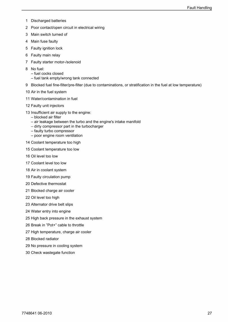
1 Discharged batteries
2 Poor contact/open circuit in electrical wiring
3 Main switch turned of
4 Main fuse faulty
5 Faulty ignition lock
6 Faulty main relay
7 Faulty starter motor-/solenoid
8 No fuel:– fuel cocks closed– fuel tank empty/wrong tank connected
9 Blocked fuel fine-filter/pre-filter (due to contaminations, or stratification in the fuel at low temperature)
10 Air in the fuel system
11 Water/contamination in fuel
12 Faulty unit injectors
13 Insufficient air supply to the engine:– blocked air filter– air leakage between the turbo and the engine's intake manifold– dirty compressor part in the turbocharger– faulty turbo compressor– poor engine room ventilation
14 Coolant temperature too high
15 Coolant temperature too low
16 Oil level too low
17 Coolant level too low
18 Air in coolant system
19 Faulty circulation pump
20 Defective thermostat
21 Blocked charge air cooler
22 Oil level too high
23 Alternator drive belt slips
24 Water entry into engine
25 High back pressure in the exhaust system
26 Break in ”Pot+” cable to throttle
27 High temperature, charge air cooler
28 Blocked radiator
29 No pressure in cooling system
30 Check wastegate function
Fault Handling
7748641 06-2010 27

Diagnostic FunctionThe diagnostic function monitors and controls that theEMS system functions normally. The diagnostic func-tion has the following tasks:
• Detecting and locating disturbances
• Reporting detection of disturbances
• Providing guidance when fault tracing
NOTICE! With the DCU:n it is possible choose the lan-guage that the inform-tion is presented in.
If the diagnostic function detects a disturbance in thesystem, this is reported using fault codes via the instru-ments.Both active (unrectified) and passive (rectified) faultsare stored in the control unit.Refer to the “Operation” heading for reading faultcodes/fault messages.All fault codes and fault messages are found in the faultcode list, with information about the reason, reactionand measures to be taken. Refer to Fault Code Reg-ister.
NOTICE! All instruments are optional.
Affect on engineEngines are affected differently, depending on theseverity of the fault discovered by the diagnostic func-tion.A fault message in the form of a fault code is alwaysgenerated when a malfunction is discovered by thediagnostic function.Engines are affected differently, depending on theseverity of the fault:
• The engine is not affected
• Engine goes to idle
• Engine torque is restricted to a certain amount
• Engine is stopped
Fault Handling
28 7748641 06-2010

Active and Inactive FaultsActive faultsAt the same time, the fault is stored in the control unitmemory. When the fault has been attended to and theignition is switched off and on again, the fault disap-pears as active.
DCU (Display Control Unit)
• text !! ENGINE WARNING !! shown on the dis-play.
CIU (Control Interface Unit)
• the diagnostic lamp starts to flash.
• ”Easy Link” instrument- the relevant lamp on the alarm panel lights up- after the diagnostic button has been pressed,the fault code is shown as text on the tachometerdisplay.
DU (Display Unit)
• Either WARNING! or ALARM STOP (a buzzersounds) will be shown on the display, dependingon the severity of the fault.
• Fault codes can also be read off using theVODIA tool. For instructions, see “VODIA User’sGuide”.
Inactive faults
• DCU – the fault is indicated as passive
• CIU – the diagnostic lamp goes out
• DU – the fault message disappears (inactivefaults cannot be read out)
• Easy Link – the lamp on the alarm panel goesout
OperationWhen a malfunction has occurred and the diagnosticsystem has generated one or more fault codes, theseare read out differently depending on the equipmentused. Please refer to Fault code messages.If the system indicates that a fault code has beenset:
1 Cut engine speed to idle, or shut the engine off.
2 For DCU/DURead the fault code from the display, pleaserefer to Reading fault codes via the DCU orReading fault codes via the DU.For CIUpress the diagnostic button and read the faultcode, by observing the flashing of the diagnosticlamp. Refer to Reading fault codes via thediagnostic lamp, CIU.
3 Look up the fault code in the Fault Code Regis-ter chapter and take the recommended meas-ures.
Reading fault codes via the DU (Display Unit)Depending on the severity of the fault the text, eitherWARNING! or ALARM STOP (a buzzer sounds) willbe shown on the display
1 Press any button to come to the fault list. Thefault list shows operation hours and fault mes-sage.
2 Look up the fault code in Fault Code Registerand take the recommended measures.
3 Press on ACK to acknowledge the fault code.The display background will change color (thebuzzer stops sounding).
4 Press on EXIT to leave the fault list.
Fault Handling
7748641 06-2010 29

Reading fault causes via the DCU (Display ControlUnit)When a fault code is set, the following text is shownon the display:!! ENGINE WARNING !!alternated withPress SEL for information.Read the fault code as follows:
1 Press SEL-button to come to the fault list.The fault list shows:-Operation hours-Fault message-Active/inactive
2 Look up the fault code in theFault Code Regis-ter chapter and take the recommended meas-ures.
3 Press ESC-button to leave the fault list.
NOTICE! To enter the fault list when no fault code hasbeen set, press the SEL button and select Diagnos-tics from the menu.
Reading fault codes via an “Easylink” instrumentWhen the system has discovered a malfunction, thisis reported by the diagnostic lamp which starts toflash.
1 Press the diagnostic button. The fault code isshown as text on the tachometer display.
2 Look up the fault code in the Fault Code Regis-ter chapter and take the recommended meas-ures.
3 When the fault has been rectified, the fault codedisappears from the display and the diagnosticlamp goes out.
Reading fault codes via the diagnostic lamp onthe instrument panel, CIUWhen the system has discovered a malfunction, thediagnostic lamp starts to flash. If the diagnostic buttonis depressed and then released, a fault code isflashed out.The fault code consists of two groups of flashes, sep-arated by a pause of two seconds. A fault code isobtained by counting the number of flashes in eachgroupExample: paus = Fault Code 2.4The fault code is stored and can be read as long asthe malfunction remains. You can find informationabout cause, reaction and actions in the Fault CodeRegister chapter.Read the fault code as follows:
1 Press the diagnostic button.
2 Release the diagnostic button and make a noteof the fault that is flashed out.
3 Repeat items 1-2. A new fault code is flashed outif more are stored. Repeat until the first faultcode is repeated.
NOTICE! When the first fault code reoccurs, all thefault codes have been read.If the diagnostics button is depressed after the faulthas been corrected and the fault code deleted, thecode 1.1, No fault, will be shown.
Erasing fault codesFault codes must be erased by an authorized VolvoPenta workshop by means of the VODIA tool.
Fault Handling
30 7748641 06-2010
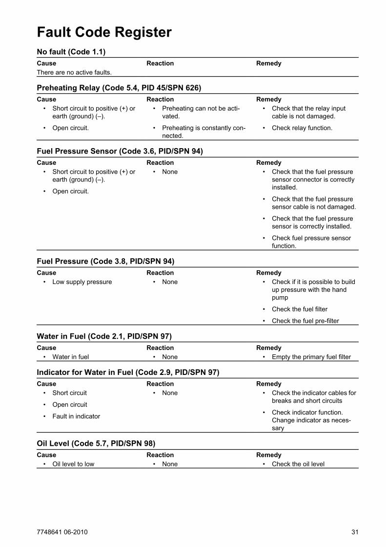
Fault Code RegisterNo fault (Code 1.1)Cause Reaction RemedyThere are no active faults.
Preheating Relay (Code 5.4, PID 45/SPN 626)Cause Reaction Remedy
• Short circuit to positive (+) orearth (ground) (–).
• Open circuit.
• Preheating can not be acti-vated.
• Preheating is constantly con-nected.
• Check that the relay inputcable is not damaged.
• Check relay function.
Fuel Pressure Sensor (Code 3.6, PID/SPN 94)Cause Reaction Remedy
• Short circuit to positive (+) orearth (ground) (–).
• Open circuit.
• None • Check that the fuel pressuresensor connector is correctlyinstalled.
• Check that the fuel pressuresensor cable is not damaged.
• Check that the fuel pressuresensor is correctly installed.
• Check fuel pressure sensorfunction.
Fuel Pressure (Code 3.8, PID/SPN 94)Cause Reaction Remedy
• Low supply pressure • None • Check if it is possible to buildup pressure with the handpump
• Check the fuel filter
• Check the fuel pre-filter
Water in Fuel (Code 2.1, PID/SPN 97)Cause Reaction Remedy
• Water in fuel • None • Empty the primary fuel filter
Indicator for Water in Fuel (Code 2.9, PID/SPN 97)Cause Reaction Remedy
• Short circuit
• Open circuit
• Fault in indicator
• None • Check the indicator cables forbreaks and short circuits
• Check indicator function.Change indicator as neces-sary
Oil Level (Code 5.7, PID/SPN 98)Cause Reaction Remedy
• Oil level to low • None • Check the oil level
7748641 06-2010 31

Oil Level Sensor (Code 5.9, PID/SPN 98)Cause Reaction Remedy
• Shorted to plus (+) or minus(-)
• Break
• None • Check that the cable harnessto the oil level sensor has notbeen damaged
• Check the oil level sensorfunction
Oil Pressure Sensor (Code 3.1, PID/SPN 100)Cause Reaction Remedy
• Short circuit to positive (+) orearth (ground) (–)
• Open circuit
• None • Check that the oil pressuresensor cable is not damaged
• Check that the oil pressuresensor is correctly connected
Oil Pressure (Code 6.6, PID/SPN 100)Cause Reaction Remedy
• Oil pressure is too low • Engine control modulereduces engine power(unless the protection hasbeen shut off with the VODIAdiagnostic tool)
• Check oil level
• Check that the air filter is notblocked
• Check system pressurevalves and safety valves inthe oil system
• Check oil pressure sensorfunction
Boost Temperature Sensor (Code 3.2, PID/SPN 105)Cause Reaction Remedy
• Short circuit to positive (+) orearth (ground) (–)
• Open circuit
• None • Check that the boost temper-ature sensor connector is cor-rectly installed
• Check that the boost temper-ature sensor cable is not dam-aged
• Check that the boost temper-ature sensor is correctlyinstalled
• Check boost temperaturesensor function
Boost Temperature (Code 6.2, PID/SPN 105)Cause Reaction Remedy
• Boost temperature is too high • Engine control modulereduces engine power(unless the protection hasbeen shut off with the VODIAdiagnostic tool)
• Check the coolant level
• Check the charge air cooler(cleanliness)
• Check boost temperaturesensor function
• Check the function of the ther-mostat
Fault Code Register
32 7748641 06-2010

Boost Pressure Sensor (Code 3.4, PID/SPN 102/106)Cause Reaction Remedy
• Short circuit to positive (+) orearth (ground) (–)
• Open circuit
• Engine smokes more thannormally during acceleration/load increase
• Check that the boost pressuresensor connector is correctlyinstalled
• Check that the boost pressuresensor cable is not damaged
• Check that the boost pressuresensor is correctly installed
• Check boost pressure sensorfunction
Boost Pressure Sensor (Code 3.5, PID/SPN 106)Cause Reaction Action
• High charge pressure • Engine power is reduced orengine stops.
• Check that the charge airpressure sensor connector iscorrectly installed
• Check that the charge airpressure sensor cable is notdamaged
• Check that the charge airpressure sensor is correctlyinstalled
• Check charge air temperaturesensor function
Air Filter Pressure (Code 5.5, PID/SPN 107)Cause Reaction Remedy
• Too large pressure dropacross filter
• Less good response fromengine
• Check the air filter
Air Filter Sensor (Code 5.6, PID/SPN 107)Cause Reaction Remedy
• Shorted to plus (+) or minus(-)
• Break
• None • Check that the air filter sensorcontact is correctly installed
• Check that the cable harnessto air filter sensor has notbeen damaged
• Check the air filter sensorfunctionality
Fault Code Register
7748641 06-2010 33

Coolant Temperature Sensor (Code 3.3, PID/SPN 110)Cause Reaction Remedy
• Short circuit to positive (+) orearth (ground) (–)
• Open circuit
• Preheating is also activatedwhen the engine is hot
• Check that the coolant tem-perature sensor connector iscorrectly installed
• Check that the coolant tem-perature sensor cable is notdamaged
• Check that the coolant tem-perature sensor is correctlyinstalled
• Check coolant temperaturesensor function
Coolant Temperature (Code 6.1, PID/SPN 110)Cause Reaction Remedy
• Coolant temperature is toohigh
• Engine control modulereduces engine power(unless the protection hasbeen shut off with the VODIAdiagnostic tool)
• Check the coolant level
• Check the charge air cooler(cleanliness)
• Check if there is air in thecooling system
• Check the pressure cap onthe expansion tank
• Check coolant temperaturesensor function
• Check thermostat function
Coolant Level (Code 2.2, PID/SPN 111)Cause Reaction Remedy
• Low coolant level • Engine control modulereduces engine power(unless the protection hasbeen shut off with the VODIAdiagnostic tool)
• Check the coolant level
• Check coolant level monitorfunction
Coolant Level Sensor (Code 2.3, PID/SPN 111)Cause Reaction Remedy
• Short circuit to positive (+)
• Fault in sensor
• None • Check that the coolant levelsensor cable is not damaged
• Check coolant level sensorfunction
Crankcase Ventilation Pressure (Code 7.7, PID/SPN 153)Cause Reaction Remedy
• Crankcase ventilation pres-sure too high
• The engine is shut down (ifthe protection has notbeenshut off by the parameter tool)
• Check whether the crankcaseventilation is blocked
• Check whether cylinder lin-ers, pistons or piston rings areworn or damaged
Fault Code Register
34 7748641 06-2010

Crankcase Ventilation Pressure Sensor (Code 7.8, PID/SPN 153)Cause Reaction Remedy
• Shorted to plus (+) or minus(-)
• Break
• None • Check that the crankcaseventilation pressure sensorcontact is correctly installed
• Check that the cable harnessto the crankcase ventilationpressure sensor has not beendamaged
• Check that the crankcaseventilation pressure sensorcorrectly installed
• Check crankcase ventilationpressure sensor function
Battery Voltage, EMS (Code 3.9, PID/SPN 158)Cause Reaction Remedy
• Faulty alternator
• Faulty battery, battery cables
• None • Check the supply voltagefrom the control unit
Battery Voltage, CIU (Code 6.9, PID/SPN 158)Cause Reaction Remedy
• Short circuit to negative (-)
• Faulty alternator
• Faulty battery, battery cables
• Problems in engine starting • Check the supply voltagefrom the control unit
• Check the batteries
• Check the alternator
• Check the 8-pin contact
Air Temperature Sensor, Inlet (Code 7.9, PID/SPN 172)Cause Reaction Remedy
• Shorted to plus (+) or minus(-)
• Break
• None • Check that the air tempera-ture sensor contact is cor-rectly installed
• Check that the cable harnessto the air temperature sensorhas not been damaged
• Check that the air tempera-ture sensor is correctly instal-led
• Check the air temperaturesensor functionality
Oil Temperature Sensor (Code 3.7, PID/SPN 175)Cause Reaction Remedy
• Shorted to plus (+) or minus(-)
• Break
• None • Check that the cable harnessto the oil temperature sensorhas not been damaged
• Check that the oil tempera-ture sensor has been con-nected correctly
Fault Code Register
7748641 06-2010 35

Oil Temperature (Code 5.8, PID/SPN 175)Cause Reaction Remedy
• Oil temperature is too high • The engine control modulelimits engine output(unlessprotection has been turned offwith thediagnosis toolVODIA)
• Check the oil level
• Check the oil temperature
• Check the oil temperaturesensor function
Engine Speed (Code 2.6, PID/SPN 190)Cause Reaction Remedy
• Engine speed too high • None • After the engine has stopped,look for the reason for the highspeed
Starter Input CIU (Code 5.2, PPID 4/SPN 520194)Cause Reaction Remedy
• Shorted to minus (-)
• Activated for too long
• The engine cannot be started
• The engine starts immedi-ately when ignition is turnedon
• Check that connections to theignition key/start panel havenot been damaged
• Check that the cable harnessto the ignition key/start panelhas not been damaged
Stop Input CIU (Code 5.3, PPID 6/SPN 52095)Cause Reaction Remedy
• Short circuit to negative (-)
• Open circuit
• Activated for too long time
• Engine can only be stoppedwith the auxiliary stop (AUXSTOP) on engine
• Engine stops. A fault code isdisplayed for 40 seconds andthe engine can not be startedduring this time. When a faultcode is active, the engine canbe started but not stopped
• Check that the starter switchconnections are not damaged
• Check that the ignition switchcable is not damaged
Stop Input EMS (Code 4.8, PPID 6/SPN 970)Cause Reaction Remedy
• Short circuit to negative (-)
• Open circuit
• Engine can only be stoppedwith the auxiliarystop
• Check that the starter switchconnections are not damaged
Start output/Start motor relay (Code 4.6, PPID 3/ SPN 677)Cause Reaction Remedy
• Shorted to plus (+) or minus(-)
• Activated for too long
• The engine cannot be started
• The engine starts immedi-ately when ignition is turnedon
• Check that connections to theignition key/start panel havenot been damaged
• Check that the cable harnessto the ignition key/sart panelhas not been damaged
Piston Cooling Pressure (Code 6.7, PPID 8/SPN 520192)Cause Reaction Remedy
• Piston cooling pressure is toolow
• Engine stopped • Check that the oil pressure inthe engine exceeds175 kPa(25.4 psi)
Fault Code Register
36 7748641 06-2010

Piston Cooling Pressure Sensor (Code 6.8, PPID 8/SPN 520192)Cause Reaction Remedy
• Shorted to plus (+) or minus(-)
• Break
• None • Check that the piston coolingpressure sensor contact iscorrectly installed
• Check that the cable harnessto the piston cooling pressuresensor has not been dam-aged
• Check the piston coolingpressure sensor functionality
Internal EGR (Code 8.5, PPID 19/SPN 2791)Cause Reaction Remedy
• Fault in cable harness (boostpressure sensor)
• Mechanical fault on the IEGR
• Engine control modulereduces engine power
• Check cable harness (boostpressure sensor)
• Check the IEGR
• Contact a Volvo Pentaauthorized workshop
ECU Temperature (Code 8.4, PPID 55/SPN 1136)Cause Reaction Remedy
• Control unit too hot, incorrectassembly
• Electrical fault, damaged sen-sor
• None • Check the control unit instal-lation. Recommended ambi-ent temperature is 50°C(122°F)
Speed Potentiometer Connected to CIU (Code 2.8, PPID 132/SPN 91, 608,)Cause Reaction Remedy
• Shorted to plus (+) or minus(-)
• Fault in sensor
• Engine goes to idle
• Speed feezes
• Check that the potentiometerhas been connected correctly
• Check that the cable harnessto the potentiometer has notbeen damaged
• Check the potentiometerfunction
SInjector, Cylinder #1 (Code 7.1, SID 1/SPN 651)Cause Reaction Remedy
• Electrical fault
• Faulty compression or injec-tor
• Engine runs on 5 cylinders
• Abnormal sound
• Reduced performance
• Check that the injector cablesare not damaged
• Check that the injector con-nections are not damaged
• Check fuel supply pressure
• Check the valve clearance
• Do a compression test andcheck cylinder #1
Fault Code Register
7748641 06-2010 37

Injector, Cylinder #2 (Code 7.2, SID 2/SPN 652)Cause Reaction Remedy
• Electrical fault
• Faulty compression or injec-tor
• Engine runs on 5 cylinders
• Abnormal sound
• Reduced performance
• Check that the injector cablesare not damaged
• Check that the injector con-nections are not damaged
• Check fuel supply pressure
• Check the valve clearance
• Do a compression test andcheck cylinder #2
Injector, Cylinder #3 (Code 7.3, SID 3/SPN 653)Cause Reaction Remedy
• Electrical fault
• Faulty compression or injec-tor
• Engine runs on 5 cylinders
• Abnormal sound
• Reduced performance
• Check that the injector cablesare not damaged
• Check that the injector con-nections are not damaged
• Check fuel supply pressure
• Check the valve clearance
• Do a compression test andcheck cylinder #3
Injector, Cylinder #4 (Code 7.4, SID 4/SPN 654)Cause Reaction Remedy
• Electrical fault
• Faulty compression or injec-tor
• Engine runs on 5 cylinders
• Abnormal sound
• Reduced performance
• Check that the injector cablesare not damaged
• Check that the injector con-nections are not damaged
• Check fuel supply pressure
• Check the valve clearance
• Do a compression test andcheck cylinder #4
Injector, Cylinder #5 (Code 7.5, SID 5/SPN 655)Cause Reaction Remedy
• Electrical fault
• Faulty compression or injec-tor
• Engine runs on 5 cylinders
• Abnormal sound
• Reduced performance
• Check that the injector cablesare not damaged
• Check that the injector con-nections are not damaged
• Check fuel supply pressure
• Check the valve clearance
• Do a compression test andcheck cylinder #5
Fault Code Register
38 7748641 06-2010

Injector, Cylinder #6 (Code 7.6, SID 6/SPN 656)Cause Reaction Remedy
• Electrical fault
• Faulty compression or injec-tor
• Engine runs on 5 cylinders
• Abnormal sound
• Reduced performance
• Check that the injector cablesare not damaged
• Check that the injector con-nections are not damaged
• Check fuel supply pressure
• Check the valve clearance
• Do a compression test andcheck cylinder #6
Camshaft Drive Speed Sensor (Code 2.5, SID21/SPN 636)Cause Reaction Remedy
• No signal
• Abnormal frequency
• Fault in sensor
• Engine takes longer to startthan normal. Engine runs nor-mally when running
• Check that the engine speedsensor connector is correctlyinstalled
• Check that the engine speedsensor cable is not damaged
• Check that the engine speedsensor is correctly installed inthe upper timing gear cover.
• Check engine speed sensorfunction.
Flywheel Speed Sensor (Code 2.4, SID 22/SPN 637)Cause Reaction Remedy
• No signal
• Abnormal frequency
• “Intermittent” signal from thesensor
• Fault in sensor
• Engine is very difficult to startand runs roughly when itstarts
• Check that the sensor con-nector is correctly installed
• Check that the engine speedsensor cable is not damaged
• Check that the engine speedsensor is correctly installed inthe flywheel housing
• Check engine speed sensorfunction
Wastegate (SID 32/SPN 1188)Cause Reaction Remedy
• Short circuit to positive (+) ornegative (-)
• Open circuit
• Wastegate damagedmechanically
• Warning lamp lights up
• Engine control unit limitsengine power
• Check that the wastegateconnector is properlymounted
• Check that the wiring to thewastegate is not damaged
• Check that the wastegate iscorrectly mounted
• Check the wastegate
Fault Code Register
7748641 06-2010 39

Preheating Sensor (Code 8.6, SID 70/SPN 729)Cause Reaction Remedy
• Fault in cable harness
• Fault in preheating relay
• Preheating can not be acti-vated
• Check the cable harness
• Check the preheating relay
Data Link (CAN), CIU (Code 6.4, SID 231/SPN 639)Cause Reaction Remedy
• Faulty data link (CAN), , CIU • Instruments and warninglamps stop working
• Check that the 8-pin connec-tor is not damaged
• Check that the cablesbetween the CIU and theengine management unit arenot damaged
Data Link (CAN), EMS 2 (Code 6.5, SID 231/SPN 639/2017/PSID 201)Cause Reaction Remedy
• Internal fault in control mod-ule
• Engine not operating: enginecan not be started. Engineoperating: engine idles andcan only be stopped with theauxiliary stop (AUX-stop)
• Check that the 8-pin connec-tor is not damaged
• Check that the cablesbetween the CIU and theengine management unit arenot damaged
• Check that sleeves 11 and 12in the connector on the CIUare not damaged
Power Supply to Sensor (Code 9.3, SID 211/232, SPN 1079/1080)Cause Reaction Remedy
• Shortcut
• Fault in sensor
• Faulty values in oil pressureand boost pressure sensors
• Fault code for oil pressure-and boost pressure sensor
• Low engine output
• The instrument shows zero oilpressure and boost pressure
• Check that the cable harnessto oil pressure and boostpressure sensor has not beendamaged
• Check oil pressure and boostpressure sensors
Memory Fault EMS (Code 9.9, SID 240/SPN 628)Cause Reaction Remedy
• Memory fault in engine man-agement system
• Engine might not start • Re-program the unit
Faulty data link (J1587) (Code 9.2, SID 250/SPN 608)Cause Reaction Remedy
• Faulty data link • None • Check that the 8-pin connec-tor is not damaged
• Check that the cablesbetween the CIU/DCU andthe engine management unitare not damaged
Fault Code Register
40 7748641 06-2010

Data Set Memory EEPROM, CIU (Code 9.8, SID 253/SPN 630)Cause Reaction Remedy
• Internal fault in control mod-ule
• Programming faulty
• Engine does not start • Re-program the control mod-ule.
Data Set Memory EEPROM, EMS (Code 9.9, SID 253/SPN 630)Cause Reaction Remedy
• Internal fault in control mod-ule
• Internal fault in control mod-ule
• Engine does not start • Re-program the control mod-ule. If the fault remains,change the control module
Fault in Control Unit, CIU (Code 9.8, SID 254/SPN 629)Cause Reaction Remedy
• Faulty EEPROM, CIU
• Faulty flash memory, CIU
• Fault in control module, CIU
• CIU returns to factory setting
• Engine goes to idle
• Engine can not be started
• Re- program the unit
Control Module EMS (Code 9.9, SID 254/SPN 629)Cause Reaction Remedy
• Internal fault in control mod-ule
• Engine misfires
• Engine does not start
• Change engine control unit
Injection Pressure (Code 8.3, PID/SPN 164)Cause Reaction Remedy
• Fault in fuel supply
• Fault in fuel pump
• Fault in harness
• Fault in sensor
• Warning lamp lights up
• Control unit reduces enginepower
• Check harness
• Check sensor
• Check fuel filter
• Check fuel pump
Fan, rpm sensor (PID 26/SPN 975)Cause Reaction Remedy
• Open circuit • Warning lamp lights up • Check that the fan actuator isproperly mounted
• Check that the wiring to thefan actuator is not damaged
• Check that the fan actuator iscorrectly mounted
• Check the fan actuator
Fault Code Register
7748641 06-2010 41

Fan actuator (SID 33/SPN 975)Cause Reaction Remedy
• Short circuit to positive (+) ornegative (-)
• Open circuit
• Fan actuator damagedmechanically
• Warning lamp lights up • Check that the fan actuator isproperly mounted
• Check that the wiring to thefan actuator is not damaged
• Check that the fan actuator iscorrectly mounted
• Check the fan actuator
Fault Code Register
42 7748641 06-2010

Maintenance ScheduleService Schedule
FSI = First Service InspectionS2 = First Time ServiceS = Lubrication serviceA – F = Type of service (regular service)
C = CleanR = ReplaceA = AdjustmentL = LubricationI = Inspect (Clean, Adjust, Lubricate or Replace if nec-essary)
FSI After the first 100-200 HoursFuel pre-filter, draining condensed water ICoolant Level IDrive Belts IStart and warm up engineCoolant/oil/fuel, leakage IInspection with VODIA (Diagnostic Tool) IEngine and transmission, abnormal noises IStop Engine
Engine Oil and Oil Filters / By-pass filter(1)(2) R
Restart engineOil pressure / oil leakage I
1) Oil change intervals vary, depending on engine type, oil grade and sulfur content of the fuel. Refer to TechnicalData page 67.2) Change filter at every oil change.
S2 After the First 1000 HoursValve clearance A
S Every 50–600 Hours / at Least Every 12 MonthsEngine Oil and Oil Filters / By-pass filter(1)(2) R
1) Oil change intervals vary, depending on engine type, oil grade and sulfur content of the fuel. Refer to TechnicalData page 67.2) Change the filters during each oil change.
A Every 500 Hours / at Least Every 12th MonthFuel Tank (sludge trap), Drain IInspection with VODIA (Diagnostic Tool) IFuel pre-filter, draining condensed water IAir Filter Inserts (Indicator), Engine IRadiator IDrive Belts IBatteries, electrolyte level I
7748641 06-2010 43

B Every 1000 Hours / at Least Every 12 MonthsFuel Filter RAir filter insert , engine RFuel pre-filter R
Coolant Filter(1) R
1) Not at same time as coolant change.
C Every 2000 HoursValve clearance I
D Every 2000 Hours / at Least Every 24th MonthTurbocharger I
Turbo, Wastegate(1) I
Engine, with Respect to Leakage IEngine, with Respect to Hose and Cable Clamping IEngine, with Respect to Cleaning and Painting IAir Filter, Tank Breather RAir Filter, Compressor R
1) TAD1350GE, TAD1351GE, TAD1352GE, TAD1353GE
E Every 4000 hour / at Least Every 24 monthBelt Tensioner IDrive Belts R
F Every 8000 Hours / at Least Every 48th MonthCoolant R
Maintenance Schedule
44 7748641 06-2010

MaintenanceThis chapter describes how the specified maintenance points in Service Schedule page 43 should be performed,where also service intervals are stated.
CAUTION!Read the chapter on Maintenance before starting work. It contains instructions on how to carry out maintenanceand service operations in a safe and correct manner.
Service and maintenance work should be done with the engine stopped unless otherwise specified. Make itimpossible to start the engine by removing the system voltage with the main switch.Working with, or approaching a running engine is a safety risk. Watch out for rotating components and hot sur-faces.
Orientation
1 Expansion tank
2 Alternator
3 Oil Filler
4 Oil dipstick
5 Aux stop
6 Control panel
7 Air filter
8 Fuel filter
9 Fuel pre filter with water separator
10 Control unit, EMS
11 Turbo
12 Starter motor
13 Oil filter
14 Coolant filter
7748641 06-2010 45
8
10
1112
13
14
P0004318
6
7
1 2 3
4
5
9
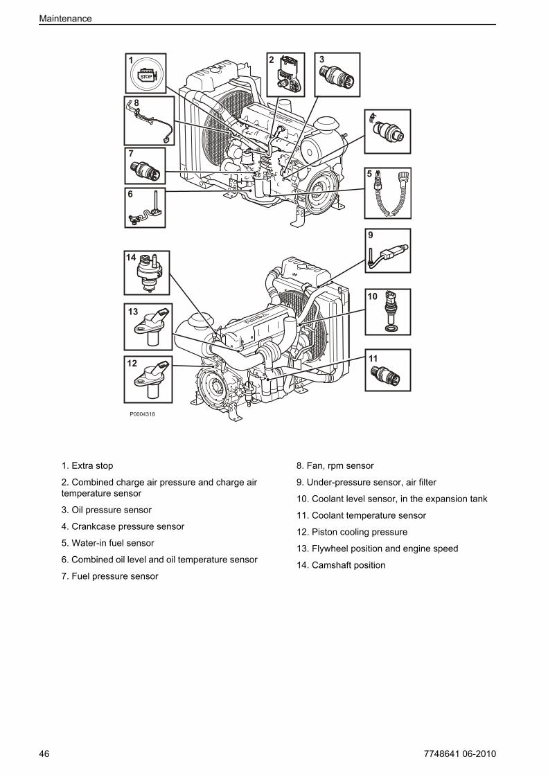
1. Extra stop
2. Combined charge air pressure and charge airtemperature sensor
3. Oil pressure sensor
4. Crankcase pressure sensor
5. Water-in fuel sensor
6. Combined oil level and oil temperature sensor
7. Fuel pressure sensor
8. Fan, rpm sensor
9. Under-pressure sensor, air filter
10. Coolant level sensor, in the expansion tank
11. Coolant temperature sensor
12. Piston cooling pressure
13. Flywheel position and engine speed
14. Camshaft position
Maintenance
46 7748641 06-2010

Engine, General
General inspectionMake it a habit to give the engine and engine bay avisual inspection before starting the engine and afteroperation once the engine has stopped. This will helpyou to discover quickly if anything abnormal has hap-pened, or is about to happen.Look especially carefully at oil, fuel and coolant leak-age, loose bolts, worn or poorly tensioned drive belts,loose connections, damaged hoses and electricalcables. This inspection only takes a few minutes andcan prevent serious malfunctions and expensiverepairs.
WARNING!Accumulations of fuel, oil and grease on the engine orin the engine room is a fire hazard and must beremoved immediately they are detected.
WARNING!If an oil, fuel or coolant leak is detected, the cause mustbe investigated and the fault rectified before the engineis started.
IMPORTANT!Remember the following when washing with a powerwasher: Never aim the water jet at radiators, charge aircooler, seals, rubber hoses or electrical components.
Air Filter, Check and ChangeThe engine is equipped with electronic air filter indica-tion.The control unit provides an output signal which isannounced as a warning on the instrument panel. Thewarning indicates a pressure drop in the air filter, whichmust then be checked and possibly changed.
• Scrap the old filter. No cleaning or re-use is permis-sible
• In continuous operation, the filter should be checkedevery 8 hours. For operations in extremely dirtyenvironments such as coal mines and rock crushingmills, special air filters must be used.
Maintenance
7748641 06-2010 47

Charge Air Pipe, Leakage Check
Inspect the condition of the charge air hoses, hoseunions and clamp condition for cracks and other dam-age. Change as necessary.
IMPORTANT!Clamps must be tightened using a torque wrench to 9±2 Nm (6.6 ±1.5 lbf.ft.).
Drive Belt and Alternator Belt,InspectionInspections must be carried out after operations, whilethe belts are hot.You should be able to depress the alternator belt andthe drive belt about 3-4 mm between the pulleys.The alternator belts and drive belts have automatic belttensioners and do not need to be adjusted.Check the condition of the drive belts. Replace as nec-essary; refer to Alternator Belts, Change page 49and Drive Belt, Change page 49.
P0002083
Maintenance
48 7748641 06-2010

Alternator Belts, ChangeIMPORTANT!Always replace a drive belt that seems worn or iscracked.
1 Disconnect the main switch(es) and check that theengine is not connected to system voltage.
2 Remove the fan guard and fan ring round the cool-ing fan.
3 Remove the belt guard.
4 Place a 1/2" square wrench in the belt tensioner (1).Lift the wrench up and lift the water pump drive beltoff.
5 Place a 1/2" square wrench in the belt tensioner (2).Press the wrench down and remove the alternatorbelt.
6 Check that the pulleys are clean and undamaged.
7 Press the 1/2" wrench in the belt tensioner (2) downand install the new alternator drive belt.
8 Lift the 1/2" wrench in the belt tensioner (1) and re-install the water pump drive belt.
9 Install the belt guards.
10 Install the fan guard and fan ring round the coolingfan.
11 Start the engine and perform a function check.
Drive Belt, Change1 Disconnect the main switch(es) and check that the
engine is not connected to system voltage.
2 Remove the fan guard and fan ring round the cool-ing fan.
3 Remove the belt guard.
4 Place a 1/2" square wrench in the belt tensioner (1).Lift the wrench and remove the drive belt.
5 Thread the drive belt round the fan and remove it.
6 Check that the pulleys are clean and undamaged.
7 Thread the new drive belt over the fan.
8 Lift the 1/2" wrench and install the new drive belt.
9 Install the belt guards.
10 Install the fan guard and fan ring round the coolingfan.
11 Start the engine and perform a function check.
Maintenance
7748641 06-2010 49

Lubrication System
Oil change intervalls may vary according to the lubri-cation oil grade and fuel sulfur content. Refer to Tech-nical data, Lubrication system.
NOTICE! Oil change intervals must never exceed aperiod of 12 months.
If longer oil change intervals than those given in Tech-nical data are required, the condition of the oil must bechecked by the oil manufacturer via regular oil tests.
Oil level, checking and topping upThe oil level must be inside the marked area on thedipstick and must be checked daily before the firststart.
• Top up with oil via the filler opening, please referto Maintenance page 45.Check that the correct level has been achieved. Ifthe engine is stationary, wait for a few minutes toallow the oil to run down into the oil pan.
• The oil level can be read both when the engine isstationary (the STOP side of the dipstick) and withthe engine running (the OPERATING side of thedipstick).Do not fill up above the maximum oillevel. Only usea recommended grade of oil, please refer to Tech-nical Data page 67.
• The oil level sensor only measures the oil level atthe time when the ignition is turned on. In otherwords, not continually during operation.
P0002089
STOP
OPERATING
P0004311
Maintenance
50 7748641 06-2010

Engine Oil, Change
WARNING!Hot oil and hot surfaces can cause burns.
Oil changes must be done when the engine is warm.
1 Connect the drain hose to the oil drain pump andcheck that no leakage can occur.
2 Pump the oil out (or remove the bottom drain plugand drain the oil).Collect all the old oil and old filters, and leave themat a re-cycling station for destruction.
3 Remove the drain hose (or install the bottom drainplug).
4 Fill with engine oil.For change volume, please refer to TechnicalData page 67.
Oil Filter/By-pass Filter, Change
WARNING!Hot oil and hot surfaces can cause burns.
1 Clean the oil filter bracket (2).
2 Remove all oil filters with a suitable oil filter extrac-tor (1).
3 Clean the mating surface of the oil filter bracket.Make sure that no remnants of old oil seal are leftbehind. Carefully clean round the inside of the pro-tective rim (2) on the oil filter bracket.
4 Put a thin layer of engine oil on the seal rings of thenew oil filters.
5 Install the new oil filters. Tighten the two full-flowfilters (on the right of the illustration) 1/2–3/4 of aturn after they bottom. Tighten the bypass filter 3/4–1 turn after it bottoms.
6 Top up with engine oil, start the engine and let it runfor 20-30 seconds.
7 Turn off the engine, check the oil level and top upas required.
8 Check the sealing round the oil filters.
P0004307
1
2
Maintenance
7748641 06-2010 51

Fuel SystemOnly use the grades of fuel recommended in the fuelspecification below, please refer to TechnicalData page 68. Always observe the greatest cleanli-ness during re-fueling and work on the fuel system.
IMPORTANT!All work on the injection system of the engine must bedone by an authorized workshop.
WARNING!Fire hazard. When carrying out work on the fuel systemmake sure the engine is cold. A fuel spill onto a hotsurface or an electrical component can cause a fire.Store fuel soaked rags so that they can not cause fire.
Engine Fuel Filter ReplacementThe fuel filter shall be replaced while the engine is cold.
WARNING!Fire hazard. When carrying out work on the fuel systemmake sure the engine is cold. A fuel spill onto a hotsurface or an electrical component can cause a fire.Store fuel soaked rags so that they can not cause fire.
Do not fill the new fuel filter with fuel before assembly.There is a risk that contamination could get into thesystem and cause malfunctions or damage.
1 Clean round the fuel filter.
2 Remove the filter with a suitable filter remover. Col-lect any spilled fuel in a collection vessel.
3 Clean the filter mating surface on the filter bracket.
4 Lubricate the seal with diesel fuel and install thenew fuel filter. Tighten the fuel filter in accordancewith the instructions on the fuel filter.
5 Where necessary, purge the fuel system; refer toBleeding the Fuel System page 53.
6 If a water trap is installed, change the filter in it atthe same time as the fuel filter, and clean the watertrap in the plastic bowl under the filter with a softrag.
P0002101
Maintenance
52 7748641 06-2010

Fuel Pre-filter, Change1 Undo the cable from the water trap sensor.
2 Remove the water trap filter from the filter bracket.Collect any spilled fuel in a collection vessel.
3 Remove the lower part of the water trap from thefilter.
4 Clean the lower part of the water trap with a soft rag.Check that the drain hole in the lower part is notblocked.
5 Install a new seal on the lower part and lubricate theseal with diesel fuel. Re-install the lower part of thefilter.
6 Lubricate the seal with diesel fuel. Screw the filteronto the filter bracket by hand until the rubber sealjust touches the mating surface. Then tighten a fur-ther half turn, no more.
7 Connect the cable to the water trap sensor.
8 Where necessary, purge the fuel system; refer toBleeding the Fuel System page 53.
Draining condensate, fuel system
1 Put a collection vessel under the fuel filter to collectthe condensate and fuel.
2 Open the drain nipple (1) in the base of the fuel pre-filter.
3 Tighten the drain tap (1) when fuel without waterstarts to run out.
Bleeding the Fuel SystemThe system does not need to be purged unless it hasbeen run completely dry. Purging is then done with thehand pump on the fuel filter bracket.
P0004327
1
Maintenance
7748641 06-2010 53
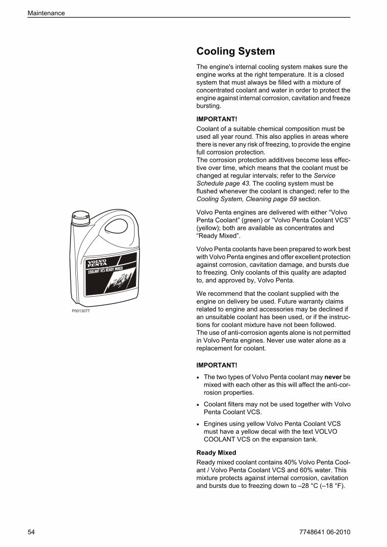
Cooling SystemThe engine's internal cooling system makes sure theengine works at the right temperature. It is a closedsystem that must always be filled with a mixture ofconcentrated coolant and water in order to protect theengine against internal corrosion, cavitation and freezebursting.
IMPORTANT!Coolant of a suitable chemical composition must beused all year round. This also applies in areas wherethere is never any risk of freezing, to provide the enginefull corrosion protection.The corrosion protection additives become less effec-tive over time, which means that the coolant must bechanged at regular intervals; refer to the ServiceSchedule page 43. The cooling system must beflushed whenever the coolant is changed; refer to theCooling System, Cleaning page 59 section.
Volvo Penta engines are delivered with either “VolvoPenta Coolant” (green) or “Volvo Penta Coolant VCS”(yellow); both are available as concentrates and“Ready Mixed”.
Volvo Penta coolants have been prepared to work bestwith Volvo Penta engines and offer excellent protectionagainst corrosion, cavitation damage, and bursts dueto freezing. Only coolants of this quality are adaptedto, and approved by, Volvo Penta.
We recommend that the coolant supplied with theengine on delivery be used. Future warranty claimsrelated to engine and accessories may be declined ifan unsuitable coolant has been used, or if the instruc-tions for coolant mixture have not been followed.The use of anti-corrosion agents alone is not permittedin Volvo Penta engines. Never use water alone as areplacement for coolant.
IMPORTANT!
• The two types of Volvo Penta coolant may never bemixed with each other as this will affect the anti-cor-rosion properties.
• Coolant filters may not be used together with VolvoPenta Coolant VCS.
• Engines using yellow Volvo Penta Coolant VCSmust have a yellow decal with the text VOLVOCOOLANT VCS on the expansion tank.
Ready MixedReady mixed coolant contains 40% Volvo Penta Cool-ant / Volvo Penta Coolant VCS and 60% water. Thismixture protects against internal corrosion, cavitationand bursts due to freezing down to –28 °C (–18 °F).
Maintenance
54 7748641 06-2010

Coolant, MixingThe concentrated coolant must be mixed with purewater (distilled or de-ionized water) according to spec-ifications; refer to Water Quality page 70.
WARNING!All coolant is hazardous and harmful to the environ-ment. Do not consume. Coolant is flammable.
IMPORTANT!Different kinds of coolant must not be mixed with eachother!
Mix: 40% concentrated coolant and 60% waterThis mixture protects against internal corrosion, cavi-tation and bursts due to freezing down to –28°C (–18°F). A 60% glycol admix lowers the freezing point to-54 °C (-65 °F).Never mix more than 60% concentrate in the coolant.A greater concentration provides reduced coolingeffect with the risk for overheating and reduced anti-freeze protection.It is extremely important that the system be filled withthe correct coolant concentration. Mix in a separateclean vessel before filling the cooling system. Makesure that the liquids mix.
Maintenance
7748641 06-2010 55

Coolant Level, Checking andTopping UpCoolant filling must be performed with the engine stop-ped. Check the coolant level daily before starting.
IMPORTANT!Only use the coolant recommended by Volvo Penta.Top up with the same type of coolant as already usedin the system. Different types of coolant must not bemixed.
WARNING!Do not open the coolant filler cap when the engine iswarm, except in emergencies, this could cause seriouspersonal injury. Steam or hot fluid could spray out.
1 Only open the filler cap (1). Do not open the pres-sure cap (2).
2 Check that the coolant level is above the MIN markon the expansion tank.
3 Top up with coolant as required, so that the level isbetween the MIN and MAX marks.Fill slowly, to allow air to flow out.
Filling a completely empty system
NOTICE! Mix the correct amount of coolant inadvance, to ensure that the cooling system is com-pletely filled. Refer to Technical Data, Cooling System,for the correct coolant volume.
Do not open the pressure cap (2).
1 Check that all drain points are closed.
2 Open filler cap (1).
3 Fill with coolant, so that the level is between the MINand MAX marks.Fill slowly, to allow air to flow out.
NOTICE! Do not start the engine until the system isvented and completely filled.
4 Start the engine when the cooling system has beencompletely filled and vented. Open any venting tapsa short while after starting, to allow trapped air toescape.If a heating unit is connected to the engine coolingsystem, the heat control valve must be opened andthe installation vented during filling.
5 Stop the engine after about an hour and check thecoolant level. Top up as necessary.
P0002095
12
P0002095
12
Maintenance
56 7748641 06-2010
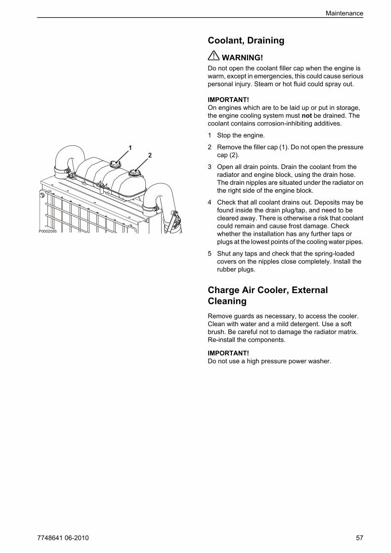
Coolant, Draining
WARNING!Do not open the coolant filler cap when the engine iswarm, except in emergencies, this could cause seriouspersonal injury. Steam or hot fluid could spray out.
IMPORTANT!On engines which are to be laid up or put in storage,the engine cooling system must not be drained. Thecoolant contains corrosion-inhibiting additives.
1 Stop the engine.
2 Remove the filler cap (1). Do not open the pressurecap (2).
3 Open all drain points. Drain the coolant from theradiator and engine block, using the drain hose.The drain nipples are situated under the radiator onthe right side of the engine block.
4 Check that all coolant drains out. Deposits may befound inside the drain plug/tap, and need to becleared away. There is otherwise a risk that coolantcould remain and cause frost damage. Checkwhether the installation has any further taps orplugs at the lowest points of the cooling water pipes.
5 Shut any taps and check that the spring-loadedcovers on the nipples close completely. Install therubber plugs.
Charge Air Cooler, ExternalCleaningRemove guards as necessary, to access the cooler.Clean with water and a mild detergent. Use a softbrush. Be careful not to damage the radiator matrix.Re-install the components.
IMPORTANT!Do not use a high pressure power washer.
P0002095
12
Maintenance
7748641 06-2010 57

Coolant Filter, ChangeNOTICE! Only applies to engines using Volvo PentaCoolant (green). Engines using Volvo Penta CoolantVCS are not fitted with coolant filters.
1 Turn the tap (1) 90° to stop the flow through thecoolant filter.
2 Remove the coolant filter with a suitable extractor.Make sure that no residue from the old seal remainsin the housing.
3 Put a thin layer of engine oil on the new coolant filterseal. Screw the coolant filter on by hand until theseal comes into contact with the mating surface ofthe filter bracket. Then tighten the coolant filter afurther 1/2 turn.
4 Turn the tap (1) 90° to release the flow through thecoolant filter again.
5 Start the engine and carry out a leakage check.
6 Switch the engine off and check the coolant level.Refer to Coolant Level, Checking and ToppingUp page 56.
Open
Closed
Maintenance
58 7748641 06-2010

Cooling System, CleaningCooling performance is reduced by deposits in theradiator and cooling galleries. The cooling systemshould be cleaned out when the coolant is changed.
IMPORTANT!Cleaning must not be done if there is any risk of thecooling system freezing, since the cleaning solutiondoes not have any frost prevention ability.
IMPORTANT!It is extremely important that the correct concentrationand volume of coolant is put in the system. Mix in aseparate clean vessel before filling the cooling system.Make sure that the liquids mix.
1 Empty the cooling system. Refer to Coolant, Drain-ing page 57.
2 Put a hose into the expansion tank filling hole andflush with clean water, as specified by Volvo Penta–refer to section Water quality in TechnicalData page 70 until the water draining out is com-pletely clear.
3 If there should still be some contamination left afterflushing for a long time, cleaning can be done withcoolant. Otherwise, continue as in item 8 below.
4 Fill the cooling system with 15-20 % mixture of con-centrated coolant. Use only Volvo Penta recom-mended concentrated coolant mixed with cleanwater.
5 Drain the coolant after 1-2 days of operation.Remove the filler cap and possibly the lower radia-tor hose to increase the speed of emptying.To prevent suspended material from settling backin the system, emptying should be done rapidly,within the space of 10 minutes, when the enginehas not been standing still for a long time.
6 Flush the system immediately and thoroughly withclean hot water to prevent dirt from settling in theinner areas. Flush until the water that runs out iscompletely clean. Make sure that any heater con-trols are set to full heating during emptying.
7 If contamination should still be left after a longperiod of flushing, you can do a cleanout with VolvoPenta radiator cleaner, followed by finishing-off withVolvo Penta neutralizer. Carefully follow theinstructions on the package. Otherwise, continueas in item 8 below.
8 When the cooling system is completely free fromcontamination, close the drain taps and plugs.
9 Fill up with Volvo Penta recommended coolant, fol-lowing the instructions in the chapters entitledMaintenance page 54and Coolant Level, Checkingand Topping Up page 56.
Maintenance
7748641 06-2010 59

Electrical SystemThe engine is equipped with a 2-pole electrical systemand an alternator. System voltage is 12V or 24V.
WARNING!Always stop the engine and break the current using themain switches before working on the engine.
Main SwitchIMPORTANT!Never disconnect the current with the main switcheswhen the engine is running, the alternator and elec-tronics could be damaged.
The main switches must never be switched off beforethe engine has stopped. If the circuit between the alter-nator and the battery is disconnected when the engineis running, the alternator and electronics can be dam-aged. For the same reason the charging circuits mustnever be re-connected with the engine running.
FusesThe engine is equipped with a 10 A circuit breakerwhich cuts the current if overloaded.The circuit breaker is located on the left-hand side ofthe engine Maintenance page 46.
The engine stops if the fuse trips. If the circuit breakertrips frequently, an authorized Volvo Penta workshopshould be contacted to investigate the cause of theoverload.
Electrical ConnectionsCheck that electrical connections are dry, free fromoxide, and that they are securely tightened. Spray theconnections as necessary with water-repellent spray(Volvo Penta universal oil).
Maintenance
60 7748641 06-2010

Battery, Maintenance
WARNING!Risk of fire and explosion. Never allow an open flameor electric sparks near the battery or batteries.
WARNING!Never confuse the positive and negative poles on thebatteries. Risk of arcing and explosion.
WARNING!The battery electrolyte contains extremely corrosivesulfuric acid. Protect your skin and clothes when charg-ing or handling batteries.Always use protective goggles and gloves. If batteryelectrolyte comes into contact with unprotected skinwhas off immediately using plenty of water and soap.If battery acid comes in contact with the eyes, flushimmediately with plenty of water and obtain medicalassistance without delay.
Connecting and disconnecting the battery
Connecting
1 Connect the + cable (red) to the + pole on the bat-tery.
2 Connect the – cable (black) to the – pole on thebattery.
Disconnecting
1 Remove the – cable (black).
2 Remove the + cable (red).
CleaningKeep the batteries clean and dry. Contamination andoxide on the batteries and battery poles can causestray currents, voltage drop and discharge, especiallyin wet weather. Remove oxidation from the batterypoles and terminals, using a brass brush. Tighten theterminals securely and grease them with terminalgrease or petroleum jelly.
P0002107
-+P0002108
Maintenance
7748641 06-2010 61
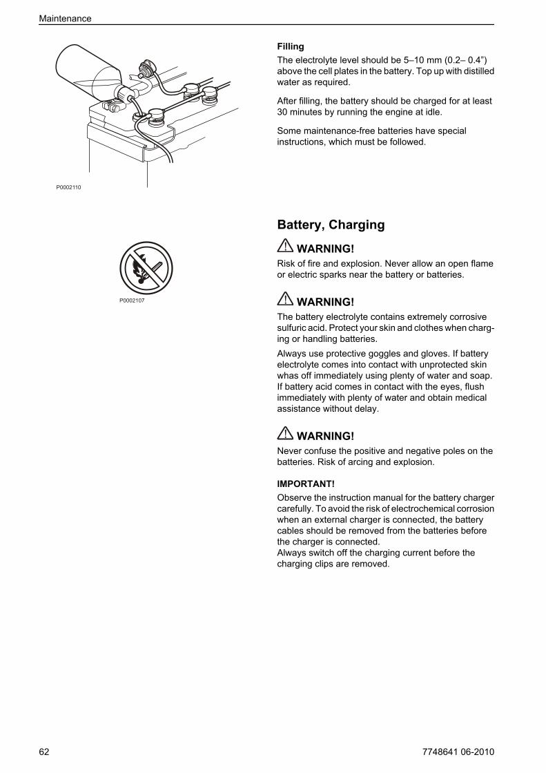
FillingThe electrolyte level should be 5–10 mm (0.2– 0.4”)above the cell plates in the battery. Top up with distilledwater as required.
After filling, the battery should be charged for at least30 minutes by running the engine at idle.
Some maintenance-free batteries have specialinstructions, which must be followed.
Battery, Charging
WARNING!Risk of fire and explosion. Never allow an open flameor electric sparks near the battery or batteries.
WARNING!The battery electrolyte contains extremely corrosivesulfuric acid. Protect your skin and clothes when charg-ing or handling batteries.Always use protective goggles and gloves. If batteryelectrolyte comes into contact with unprotected skinwhas off immediately using plenty of water and soap.If battery acid comes in contact with the eyes, flushimmediately with plenty of water and obtain medicalassistance without delay.
WARNING!Never confuse the positive and negative poles on thebatteries. Risk of arcing and explosion.
IMPORTANT!Observe the instruction manual for the battery chargercarefully. To avoid the risk of electrochemical corrosionwhen an external charger is connected, the batterycables should be removed from the batteries beforethe charger is connected.Always switch off the charging current before thecharging clips are removed.
P0002110
P0002107
Maintenance
62 7748641 06-2010

• Charge batteries if they have become discharged.During charging, unscrew the cell plugs but leavethem in the plug holes. Ventilate well, especially ifthe batteries are charged in an enclosed space.
• If the engine is not used for a longer period of time,the batteries should be fully charged, then possiblytrickle charged (please refer to the battery manu-facturer’s recommendations). Batteries are dam-aged by being left discharged, and can also freezeand burst easier in cold weather.
• Special instructions apply to boost charging. Boostcharging can shorten battery life, and should there-fore be avoided.
P0002111
Maintenance
7748641 06-2010 63

StorageThe engine and other equipment must be laid up to prevent damage if they are not used for two months or more.It is important that this is done in the correct manner, and nothing is forgotten. For this reason, we have compileda check list of the most important points.Before the engine is taken out of service for a long period of time, an authorized Volvo Penta workshop shouldcheck it over. Have any faults and deficiencies attended to, so that the equipment is in order, ready for the nextstart.
CAUTION!Read the chapter on Maintenance before starting work. It contains instructions on how to carry out maintenanceand service operations in a safe and correct manner.
WARNING!Conservations oils can be flammable and dangerous to breathe. Ensure good ventilation. Use a protective facemask when spraying.
IMPORTANT!Remember the following when washing with a high pressure washer: Never aim the water jet at seals, rubberhoses or electrical components.
• For up to 8 month’s stoppage:Change the oil and oil filter on the engine, then warmit up afterwards.More than 8 month's stoppage:Conserve the lubrication and fuel systems with con-servation oil. Please refer section Conservation ofthe lubrication and fuel systems for more than 8months’ stoppage:.
• Check that the coolant offers sufficient frost protec-tion. Top up as necessary.Alternatively, you can drain the coolant (also drainthe coolant filter).
• Drain any water and contamination from the fuel fil-ters and fuel tank. Fill the fuel tank completely, toavoid condensation.
• Disconnect the battery cables, clean and charge thebatteries. Trickle charge the batteries while theequipment is in storage.A poorly charged batterycan freeze and burst.
• Clean the outside of the engine. Do not use a highpressure washer for engine cleaning. Touch uppaint damage with Volvo Penta original paint.
• Spray the components of the electrical system withwater-repellent spray.
• Check and rust-proof any control cables.
• Put a note on the engine with the date, type of con-servation and the conservation oil used.
• Cover over the air filter, exhaust pipe and engine ifnecessary.
P0002089
64 7748641 06-2010
Bringing out of storage• Remove any covers from the engine, air filter
and exhaust pipe.
• Put the correct grade of oil into the engine, ifnecessary, refer to Tekniska data, smörjsys-tem. Install a new oil filter if the filter was notchanged during conservation.
• Install new fuel filters and vent the fuel system.
• Check the drive belt(s).
• Check the condition of all rubber hoses, andretighten the hose clamps.
• Close the drain taps and install any drainplugs.
• Check the coolant level. Top up as necessary.
• Connect the fully charged batteries.
• Start the engine and warm it up at fast idle withno loading.
• Check that no oil, fuel or coolant leakage occurs.
Conservation of the lubrication and fuel systems for more than 8 months’ stoppage:• Drain the engine oil and fill up with conservation
oil* to just over the MIN marking on the dipstick.
• Connect the fuel suction and return hoses to a 1/3full jerrican containing conservation oil* and 2/3diesel fuel.
• Vent the fuel system.
• Start the engine and run at a fast idle until about 2liters (0.6 US gals) of the fluid in the jerrican havebeen used. Stop the engine and connect the ordi-nary fuel pipes.
• Drain the engine’s conservation oil.
• Follow the other instructions on the previous page.* Conservation oils are sold by oil companies.
Storage
7748641 06-2010 65

Technical Data
EnginesType designation TAD1341/42/43/44/45GEPower, Prime/Stand-by Refer to the sales literatureTorque, Prime/Stand-by Refer to the sales literatureNo. of cylinders 6Cylinder diameter mm/inches 131/5.16Stroke, mm/inches 158/6.22
Cylinder volume, dm3/in3 12,78/779.7
Wet weight (engine only), kg/lb 1325/2921Wet weight (incl. cooling system, air filter and frame), kg/lb 1790/3946Firing order 1-5-3-6-2-4Compression ratio 18,1:1Low idle, rpm 900High idle, rpm 1500/1800
Type designation TAD1350/51/52/53/54/55GEPower, Prime/Stand-by Refer to the sales literatureTorque, Prime/Stand-by Refer to the sales literatureNo. of cylinders 6Cylinder diameter mm/inches 131/5.16Stroke, mm/inches 158/6.22
Cylinder volume, dm3/in3 12,78/779.7
Dry weight (excl. cooling system), kg/lb 1295/2855Wet weight (excl. cooling system), kg/lb 1325/2921Firing order 1-5-3-6-2-4Compression ratio 18.1:1Low idle, rpm 900High idle, rpm 1800
Type designation TAD1340/41/42/43/44/45VEPower, Prime/Stand-by Refer to the sales literatureTorque, Prime/Stand-by Refer to the sales literatureNo. of cylinders 6Cylinder diameter mm/inches 131/5.16Stroke, mm/inches 158/6.22
Cylinder volume, dm3/in3 12,78/779.7
Wet weight (engine only), kg/lb 1325/2921Wet weight (Power Pac), kg/lb 1790/3946Firing order 1-5-3-6-2-4Compression ratio 18.1:1Idle, rpm 600–1200
66 7748641 06-2010

Lubrication SystemOilChange volume, including filter change, liter/US gal 36 / 9.5
Oil pressure, hot engineat operating speed, kPa/psi 370-520 / 54–75at idle, min, kPa 250 / 39
Oil filterFull flow filter 2By-pass filter 1
Lube oil pumpType Gear driven
Oil recommendations
Oil garde
Sulfur content in fuel, by weightup to 0.5 % 0.5 – 1.0 % more than 1.0 % 1)
Oil change interval: Reached first in operation:VDS-3 600 hrs / 12 month 300 hrs / 12 month 150 hrs / 12 month
VDS-2 and ACEA: E7 2)
VDS-2 and ACEA: E5 2)
VDS-2 and Global DHD-1 2)
VDS-2 and API: CI-4 2)
VDS-2 and API: CH-4 2)
400 hrs / 12 month 200 hrs / 12 month 100 hrs / 12 month
VDS and ACEA: E3 2) 200 hrs / 12 month 100 hrs / 12 month 50 hrs / 12 month
NOTICE! Mineral based oil, as well as fully or semi-synthetic, can be used on condition that it complies with thequality requirements above.1) If sulfur content is > 1.0 % by weight, use oil with TBN > 15.
2) Lubrication oil must comply with both requirements. Note API: CG-4 or CH-4 can be approved in markets outside Europe (instead of ACEA
E3).ACEA E3).
VDS = Volvo Drain SpecificationACEA = Association des Constructeurs Européenne d’AutomobilesAPI = American Petroleum Institute GlobalDHD = Global Diesel Heavy DutyTBN = Total Base Number
Technical Data
7748641 06-2010 67

ViscositySelect the viscosity from the adjacent table, for theappropriate continuous ambient air temperature.*Refers to synthetic or semi-synthetic oils
Fuel SystemFeed pumpFeed pressure at 600 rpm min 100 kPa (14.5 psi)Feed pressure at 1200 rpm min 300 kPa (43,5 psi)Feed pressure at full load min 300 kPa (43,5 psi)
Bypass valveOpening pressure 400-550 kPa (58–80 psi)
Fuel specificationThe fuel must comply with national and international standards for commercially supplied fuels, such as:EN 590 (with nationally adapted environmental and cold weather requirements)ASTM D 975 No 1-D och 2-DJIS KK 2204Sulfur content: Complying with legal requirements in each country. If the sulfur content exceeds 0.5 weight-percent, the oil change intervals shall be changed, refer to Technical Data page 67.
Extremely low sulfur content fuel (urban diesel in Sweden and city diesel in Finland) can cause a loss of up to 5% of power and an increase in fuel consumption of about 2-3 %.
BiodieselBiodiesel is also known as Fatty Acid Methyl Esters (FAME).
Volvo Penta accepts max 5% FAME in diesel fuel, in accordance with EN590, to be used without any restraint inservice recommendations.
Volvo Penta accepts extended FAME use up to 30% blend in diesel fuel for engines produced after Jan 1-2009,under specific conditions and with certain limitations. Specific service requirements are applied for fuel blendswith more than 5% FAME.
Engines that are manufactured by Volvo Penta are certified for the use of market diesel fuel according to EN 590.Emission requirements according to EU Stage 3A will only be met with the prescribed EN 590 diesel fuel. At thedate of this document En 590 diesel fuel may contain up to 5% FAME.
Technical Data
68 7748641 06-2010

ConditionsVolvo Penta engines of above are able to run with fuel blends containing up to 30% FAME under specific condi-tions:• Oil quality VDS-3 or VDS-4 must be used.• FAME must comply with EN 14214(1).• Diesel fuel in which FAME is mixed must comply with EN 590(2).• Specific service requirements must be fulfilled. See Service Bulletin 18-8-8, contact your Volvo Penta servicedealer.
The fuel must comply with nationally laws and regional/local provisions regarding the use of FAME. The engineoperator has the responsibility of using the fuel that is recommended by the manufacturer and allowed by thenational legislation.
Normal rapeseed oil and other pure vegetable and animal oils do not meer EN 14214 and may not be used asfuel or as fuel additives. These products are not approved by Volvo Penta and warranties do not apply in the eventof engine damage.
1) European standard that describes the quality requirements and test methods for FAME.2) European standard that describes the quality requirements and test methods for Diesel.
PerformanceThe energy value of FAME is lower than for standard diesel fuel. The use of 30% FAME can result in an increasein fuel consumption with up to 5% and decrease maximum power performance by up to 4%. The engine fuelconsumption data is only valid for diesel and will give incorrect readings if FAME blends are used.
Predictive maintenance on oil drain is not applicable. The exhaust fumes might smell different and visible smokemight be seen during starting when using FAME.
Technical Data
7748641 06-2010 69

Cooling SystemType Preassurized, sealedPressure cap, max opening pressure, kPa/psi 70 / 10.2
Volume (engine), liter US gal 20 / 5.28
Volume (engine+radiator and hoses), liter/US gal 24 / 6,34
ThermostatNumber 1 pcsOpening temperature 82° C / 180° F
Water Quality
ASTM D4985:
Total solid particles <340 ppmTotal hardness <9.5° dHChloride <40 ppmSulfate <100 ppmpH value 5.5–9Silica (acc. ASTM D859) <20 mg SiO2/l
Iron (acc. ASTM D1068) <0.10 ppmManganese (acc. ASTM D858) <0.05 ppmConductivity (acc. ASTM D1125) <500 µS/cmOrganic content, CODMn (acc.ISO8467)
<15 mg KMnO4/l
Electrical SystemSystem voltage 24V
Alternatorvoltage/max. current 28V/80Apower app. 2200W
Battery capacity 2 pcs. series connected 12 V, max. 225 Ah
Battery electrolyte specific gravity at +25 °C:fully charged battery 1.28 g/cm3 (1.24 g/cm3)*batteriet omladdas vid 1.20 g/cm3 (1.20 g/cm3)*
* Note. Applies to batteries with tropical acid.
P0002094
Technical Data
70 7748641 06-2010
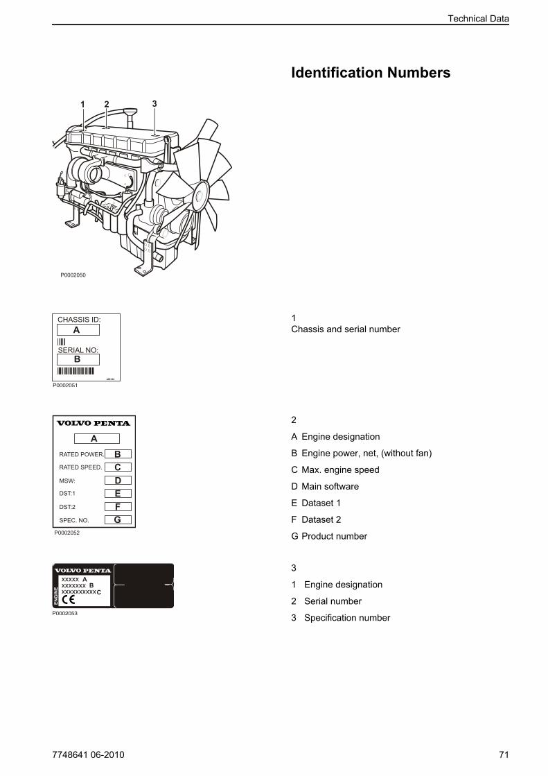
Identification Numbers
1 2 3
P0002050
1Chassis and serial number
2
A Engine designation
B Engine power, net, (without fan)
C Max. engine speed
D Main software
E Dataset 1
F Dataset 2
G Product number
3
1 Engine designation
2 Serial number
3 Specification number
P0002051
ABCDEFG
P0002052
P0002053
Technical Data
7748641 06-2010 71
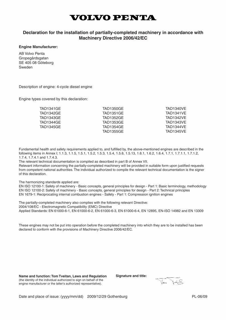
Fundamental health and safety requirements applied to, and fulfilled by, the above-mentioned engines are described in the following items in Annex I; 1.1.3, 1.1.5, 1.5.1, 1.5.2, 1.5.3, 1.5.4, 1.5.6, 1.5.13, 1.6.1, 1.6.2, 1.6.4, 1.7.1, 1.7.1.1, 1.7.1.2, 1.7.4, 1.7.4.1 and 1.7.4.3.The relevant technical documentation is compiled as described in part B of Annex VII.Relevant information concerning the partially-completed machinery will be provided in suitable form upon justified requests from competent national authorities. The individual authorized to compile the relevant technical documentation is the signer of this declaration.
The harmonizing standards applied are:EN ISO 12100-1: Safety of machinery - Basic concepts, general principles for design - Part 1: Basic terminology, methodologyEN ISO 12100-2: Safety of machinery - Basic concepts, general principles for design - Part 2: Technical principlesEN 1679-1: Reciprocating internal combustion engines - Safety - Part 1: Compression ignition engines
The partially-completed machinery also complies with the following relevant Directive:2004/108/EC - Electromagnetic Compatibility (EMC) DirectiveApplied Standards: EN 61000-6-1, EN 61000-6-2, EN 61000-6-3, EN 61000-6-4, EN 12895, EN-ISO 14982 and EN 13309
Declaration for the installation of partially-completed machinery in accordance with Machinery Directive 2006/42/EC
Engine Manufacturer:
AB Volvo PentaGropegårdsgatanSE 405 08 GöteborgSweden
Description of engine: 4-cycle diesel engine
Engine types covered by this declaration:
TAD1341GETAD1342GETAD1343GETAD1344GETAD1345GE
TAD1350GETAD1351GETAD1352GETAD1353GETAD1354GETAD1355GE
These engines may not be put into operation before the completed machinery into which they are to be installed has been declared to conform with the provisions of Machinery Directive 2006/42/EC.
Date and place of issue: (yyyy/mm/dd) 2009/12/29 Gothenburg PL-06/09
Name and function: Tom Tveitan, Laws and Regulation(the identity of the individual authorized to sign on behalf of the engine manufacturer or the latter's authorized representative).
Signature and title:
TAD1340VETAD1341VETAD1342VETAD1343VETAD1344VETAD1345VE
Operator's Manual OrderThis Operator’s Manual may be ordered in a differentlanguage free of charge up to 12 months after delivery,via internet.
Please refer to the link below. On the web page, typein the publication number found in the bottom of thispage (7–8 digits).
http://vppneuapps.volvo.com/manual/coupon/
If internet access isn't possible, please contact yourVolvo Penta dealer.
All order information is stored internally at AB VolvoPenta and will not be shared with third parties.
7748641 06-2010 73


After Engine Shutdown......................................... 23Air Filter, Check and Change.................................. 47Alarms..................................................................... 22Alternator Belts, Change......................................... 49Battery, Charging.................................................. 62Battery, Maintenance.............................................. 61Before Engine Shutdown......................................... 23Before Starting........................................................ 18Bleeding the Fuel System....................................... 53Charge Air Cooler, External Cleaning................. 57Charge Air Pipe, Leakage Check............................ 48CIU (Control Interface Unit)..................................... 17Coolant Filter, Change............................................ 58Coolant Level, Checking and Topping Up............... 56Coolant, Draining..................................................... 57Cooling System, Cleaning....................................... 59DCU (Display Control Unit)............................. 11, 19Declaration of Conformity........................................ 72Diagnostic Function................................................. 28Draining condensate, fuel system........................... 53Drive Belt and Alternator Belt, Inspection................ 48Drive Belt, Change.................................................. 49DU (Display Unit)..................................................... 17Easy Link Instruments.......................................... 17Electrical Connections............................................. 60EMS (Engine Management System)................. 10, 19Engine Fuel Filter Replacement.............................. 52Engine Oil, Change................................................. 51Engine, General...................................................... 47Engines................................................................... 66Extra Stop................................................................ 24Fault Tracing.......................................................... 26Fuel Pre-filter, Change............................................ 53Fuel System...................................................... 52, 68Identification Numbers......................................... 71Lubrication System......................................... 50, 67Main Switch............................................................ 60Maneuvering............................................................ 22Never Use Start Spray........................................... 20Oil Filter/By-pass Filter, Change.......................... 51Oil level, checking and topping up........................... 50Orientation............................................................... 45Reading the Instruments...................................... 22Service Schedule................................................... 43Starting in Extreme Cold......................................... 20Starting the Engine.................................................. 19Starting Using Auxiliary Batteries............................ 21Stop the Engine....................................................... 23Water Quality......................................................... 70
Alphabetical index
7748641 06-2010 75


© 2010 AB VOLVO PENTA Volvo reserves the right to make changes Printed on environmentally friendly paper

7748641 English 06-2010