operator's manualoperator's manual z4822/968999301 z4824/968999303 please read the...
TRANSCRIPT

Operator's manualZ4822/968999301
Z4824/968999303
Please read the operator's manualcarefully and makesure you understand the instructions before using the machine.
English
Husqvama'- Z4822 Page 1 of 2
Great experience
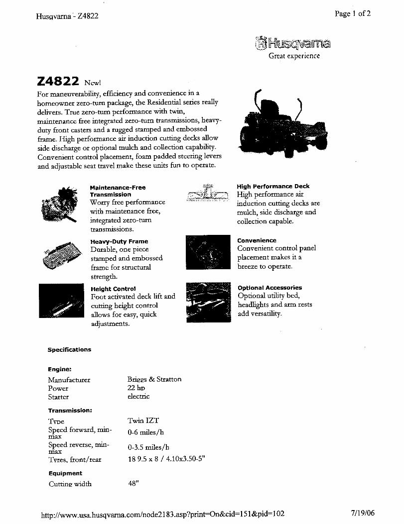
Z4822 New!For maneuverability, efficiency and convenience in a
homeowner zero-turu package, the Residential series really
delivers. True zero-turn performance with twin,
maintenance free integrated zero-turn transmissions, heavy-
duty front casters and a rugged stamped and embossed
frame. High perfomaance air induction cutting decks allow
side discharge or optional mulch and collection capability.
Convenient control placement, foam padded steering levers
and adjustable seat travel make these units fun to operate.
Maintenance-FreeTransmission
Wom-y free performancewith maintenance free,
integrated zero-turntransmissions.
Heavy-Duty FrameDoxable, one piece
stamped and embossedframe for structural
strength.
Height ControlFoot activated deck lift and
cutting height control
allows for easy, quick
adjustments.
.....7%,'7<?
High Performance Deck
High performance air
induction cutting decks are
mulch, side discharge and
collection capable.
ConvenienceConvenient control panel
placement makes it a
breeze to operate.
Optional AccessoriesOptional utility bed,
headlights and arm rests
add versatility.
Specifications
Engine:
Manu_cturerPower
Starer
Transmission:
YvDe
Speed forward, rain-max
Speed reverse, rain-max
Tvres. front/rear
Bri_s & Stratton
22 hD
decttic
Twin IZT
0-6 miles/h
0-3.5 miles/h
18 9.5 x 8 / 4.10x3.50-5"
Equipment
Cuttin_ width 48"
http ://www.usa.husqvarna.com/node2183 .asp?print=-On&cid = 151 &pid = 102 7/19/06

Husqvmma"-Z4822 Page2 of 2
Cuttin_ height 1.5-4.5 in 1/2" increments"
Number of blades 3
Blade length 19"
Anti-scalD rollers 4
Sprung standard Standard w/o armrestseat
Dual levers with foam paddedhand _iDs
12 g'4.uge, stamped steel,powder coated
Blade engagement
Deck construction
Productivity
Overall dimensions
Base machine(LxWxI-B
72x59x42"
http://www.usa.husqvarna.conffnode2183.asp?print=On&cid = 151 &pid = 102 7/19/06
OPERATOR'S MANUAL
RIDER
Z SERIES
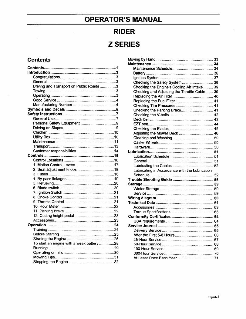
Contents
Contents ................................................................... 1Introduction ............................................................. 3
Congratulations.................................................... 3General ................................................................ 3Drivingand Transport on PublicRoads ............... 3Towing ................................................................. 3Operating ............................................................. 3Good Service ....................................................... 4ManufacturingNumber ........................................ 4
Symbols and Decals ............................................... 5Safety Instructions .................................................. 7
General Use ......................................................... 7Personal Safety Equipment ................................. 9Drivingon Slopes................................................. 9Children.............................................................. 10UtilityBox ........................................................... 10Maintenance ...................................................... 11Transport............................................................ 13Customer responsibilities................................... 14
Controls ................................................................. 16Control Locations............................................... 161. Motion Control Levers.................................... 172. Seat adjustment knobs.................................. 183. Fuses ............................................................. 184. By pass linkages ............................................ 195. Refueling........................................................ 206. Blade switch................................................... 207. IgnitionSwitch................................................ 218. Choke Control................................................ 219. Throttle Control .............................................. 2110. Hour Meter ................................................... 2211. ParkingBrake .............................................. 2212. Cutting height pedal ..................................... 23Accessories........................................................ 23
Operation ............................................................... 24Training .............................................................. 24Before Starting ................................................... 25Starting the Engine ............................................ 25To start an engine with a weak battery .............. 28Running.............................................................. 29Operating on hills............................................... 30Mowing Tips....................................................... 31Stopping the Engine........................................... 32
Moving by Hand ..................................................... 33Maintenance ......................................................... 34
Maintenance Schedule ...................................... 34Battery ............................................................... 36Ignition System .................................................. 37Checking the Safety System ............................. 38Checking the Engine's Cooling Air Intake ......... 39Checking and Adjusting the Throttle Cable ....... 39Replacing the Air Filter ...................................... 40Replacing the Fuel Filter ................................... 41Checking Tire Pressures ................................... 41Checking the Parking Brake .............................. 41Checking the V-belts ......................................... 42Deck belt ........................................................... 42EZT belt............................................................. 44Checking the Blades ......................................... 45Adjusting the Mower Deck ................................ 46Cleaning and Washing ...................................... 50Caster Wheels ................................................... 50Hardware ........................................................... 50
Lubrication ............................................................ 51Lubrication Schedule ......................................... 51General ............................................................. 51Lubricating the Cables ...................................... 52Lubricating in Accordance with the LubricationSchedule ........................................................... 52
Trouble Shooting Guide ...................................... 56Storage .................................................................. 59
Winter Storage .................................................. 59Service .............................................................. 59
Wiring diagram ..................................................... 60Technical Data ...................................................... 61
Accessories....................................................... 63Torque Specifications ........................................ 63
Conformity Certificates ........................................ 64USA requirements ............................................. 64
Service Journal .................................................... 65Delivery Service ................................................ 65After the First 5-8 Hours .................................... 6625-Hour Service ................................................ 6750-Hour Service ................................................ 68I g0-Hour Service .............................................. 69300-Hour Service .............................................. 70At Least Once Each Year .................................. 71
English-1
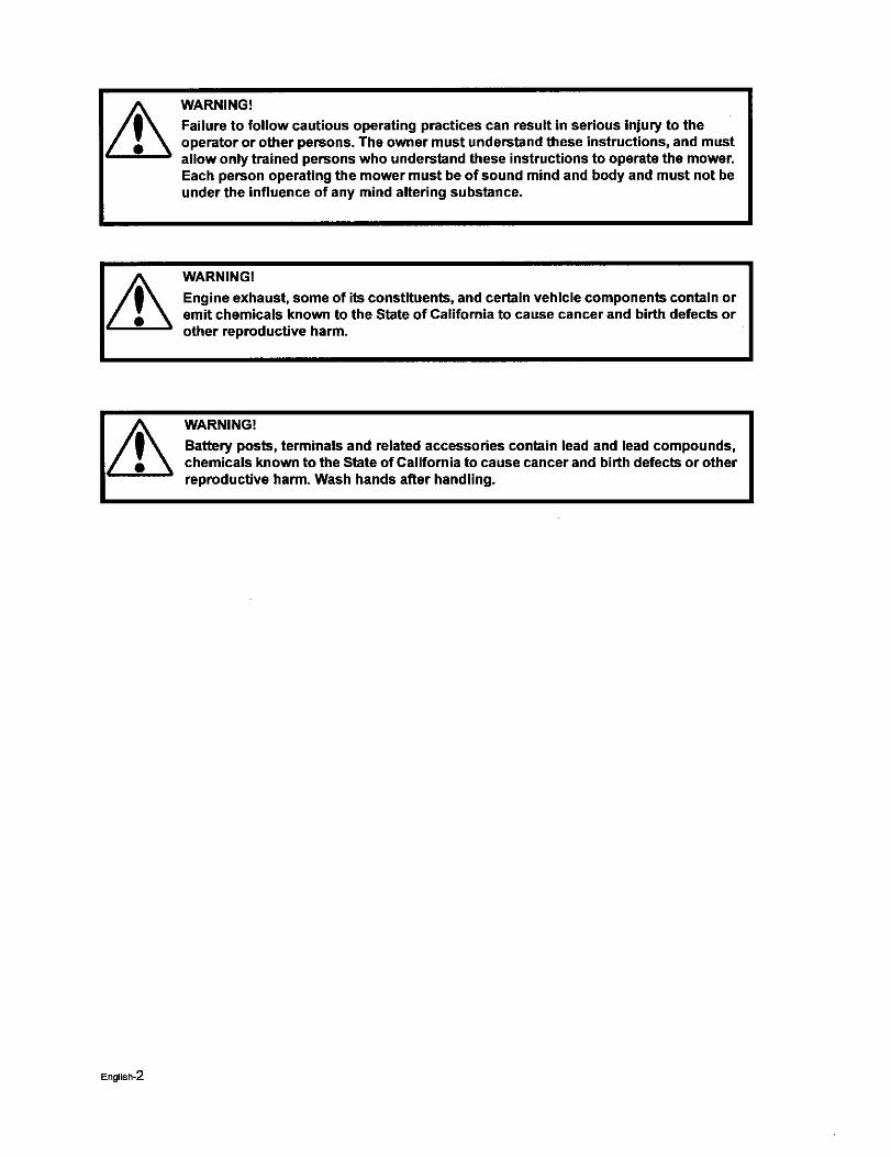
WARNING!
Failure to follow cautious operating practices can result in serious injury to theoperator or other persons. The owner must understand these instructions, and mustallow only trained persons who understand these instructions to operate the mower.Each person operating the mower must be of sound mind and body and must not beunder the influence of any mind altering substance.
WARNING!
Engine exhaust, some of its constituents, and certain vehicle components contain oremit chemicals known to the State of California to cause cancer and birth defects orother reproductive harm.
WARNING!
Battery posts, terminals and related accessories contain lead and lead compounds,chemicals known to the State of California to cause cancer and birth defects or otherreproductive harm. Wash hands after handling.
English-2
INTRODUCTION
Introduction
Congratulations
Thank you for purchasing a Husqvama ride-on mower. This machine is built for the greatest efficiencyandrapid mowing pdmarily of large areas. Controls in one place and a hydrostatic transmission regulated bysteering controls also contribute to the machine's performance.
This manual is a valuable document. Following the instructions (use, service, maintenance, etc.) by all whooperate this machine can considerably increase the lifespan of your machine and even increase its resalevalue. It is also very important to follow the instructions for the safety of you and others.
If you sell your machine, be sure to give the operator's manual to the new owner.
The final chapter of this operator's manual comprises a Service Journal. Ensure that service and repairwork is documented. A well kept service joumal reduces service costs for the saason-basad maintenanceand affects the machine's resale value. Take the operator's manual along when the machine is left to theworkshop for service.
General
In this operator's manual, left and right, backward and forward are used in relation to the machine's normalddving direction.
Continuous dedication to improve our products require that specifications and design are subject to changewithout notice.
Driving and Transport on Public Roads
Check applicable road traffic regulations before transportingon publicroads. If the machine is transported,you must always use approved fasteningequipment and ensure that the machine is well anchored. DONOT operate this machine on publicroadways.
Towing
Do not tow this machine, it may cause damage to the drive system.
Do not tow any trailers, etc withthis mower. They may jackknife or overturn causingdamage to the mowerand possiblysedous injuryto the operator.
Operating
This machine is constructed onlyfor mowinggrass on lawns and other free and even ground withoutobstacles such as stones, tree stubs, etc. The machine can also be used for other tasks when equippedwith special accessories provided by the manufacturer, for which the operating instructions are provided inconjunction with delivery. All other types of use ere incorrect. The manufacturer's directions concerningoperation, maintenance, and repairs must be carefully followed.
Lawnmowers and all power equipment, can be potentiallydangerous if used improperly.Safety requiresgood judgement, careful use in accordance with these instructions and common sense.
The machine must only be operated, maintained, and repaired by persons that are familiar withthemachine's special characteristics and who are well versed in the safety instructions. Use only approvedrepair parts to maintain this machine.
Accident prevention regulations, other general safety regulations, occupationalsafety rules, and trafficregulations must be followed without fail.
Unauthorized modifications to the design of the machine may absolve the manufacturerfrom liability forany resulting personal injury or property damage.
English-3
INTRODUCTION
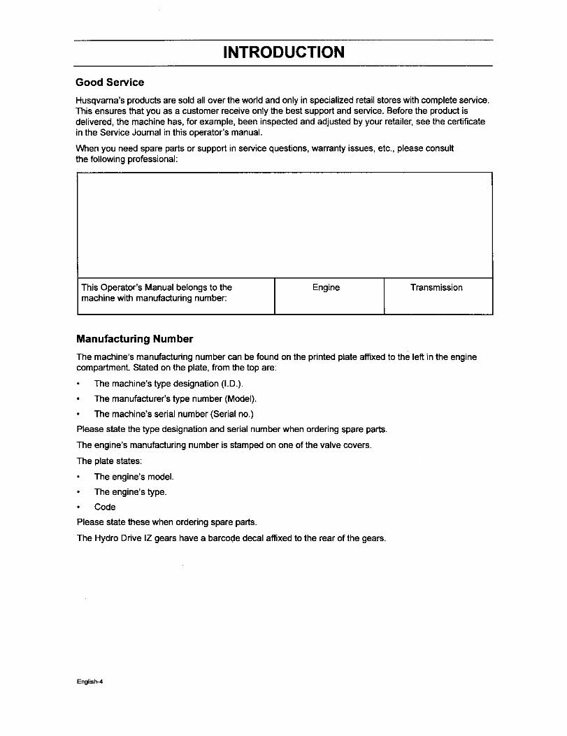
Good Service
Husqvama's productsare sold allover the worldand only inspecialized retail storeswithcomplete service.This ensures that you as a customer receive only the best supportand service. Before the productisdelivered, the machine has, for example, been inspectedand adjustedby your retailer, see the certificateinthe Service Journal in thisoperator's manual.
When you need spare parts or support in servicequestions,warranty issues, etc., please consultthe following professional:
This Operator's Manual belongs to the Engine Transmissionmachine with manufacturingnumber:
Manufacturing Number
The machine's manufacturing number can be found on the printed plate affixedto the left in the enginecompartment. Stated on the plate, from the top are:
The machine's type designation (I.D.).
The manufacturer's type number (Model).
The machine's serial number (Serial no.)
Please state the type designation and serial numberwhen orderingspare parts.
The engine's manufacturingnumber is stamped on one of the valve covers.
The plate states:
The engine's model.
The engine's type.
Code
Please state these when ordering spare parts.
The Hydro Drive IZ gears have a barcede decal affixed to the rear of the gears.
English_l
SYMBOLS AND DECALS
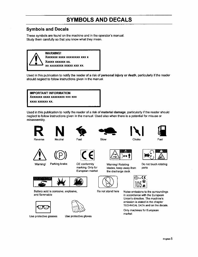
Symbols and Decals
These symbolsare found on the machine and in the operator's manual.Studythem carefullyso that you knowwhat they mean.
WARNING!Xxxxxxx xxxx xxx_xxx xxx x
Xxxxx xxxxxx xx.XX X](XXXXXX XXXXX XXX XX.
Used in this publication to notify the reader of a riskof personal injury or death, particularlyif the readershould neglect to followinstructionsgiven inthe manual.
IIMPORTANT INFORMATION
Xxxxxxx xxxx xxxxxxxx xxx xxx
XXXX XXXXXX XX. IUsed inthis publication to notify the reader of a risk of material damage, particularlyif the reader shouldneglect to follow instructionsgiven in the manual. Used also when there is a potentialfor misuseormisassembly.
R N I',,IReverse Neutral Fast Slow Choke Fuel
Warning! Parkingbrake CE conformity WamingtRotatingmarking.Onlyfor blades,keepawayfromEuropeanmarket thedischargedeck
Battery acid is corrosive, explosive,and flammable
Use protectiveglasses
%Use protectivegloves
Donot standhere
Do not touch rotatingparts
Noiseemissionstothe surroundingsinaccordansewiththe EuropeanUnion'sdirective.Themachine'semissionisstatedinthechapterTECHNICALDATAandonthedecals.
Only machines for Europeanmarket
English-5
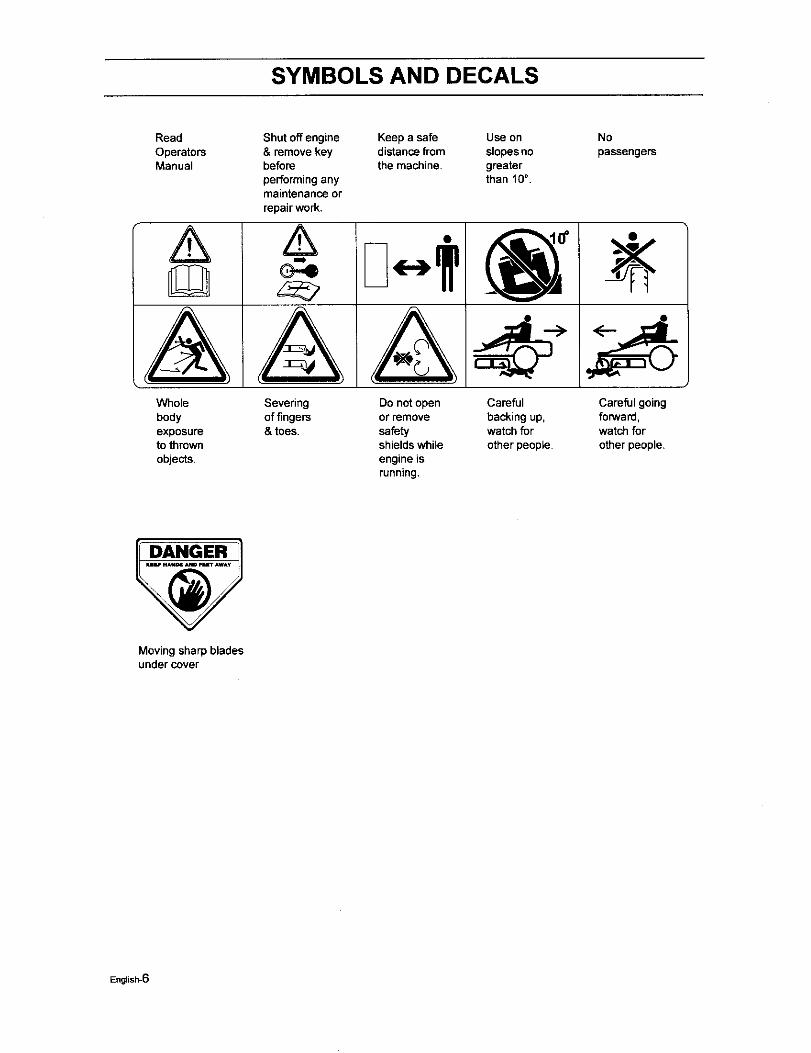
SYMBOLS AND DECALS
Read
OperatorsManual
A
VVhole
bodyexposuretothmwn
o_e_s.
Shut off engine& remove keybefore
performinganymaintenance or
repair work.
&
A
Keep a safe Use ondistance from slopesnothe machine, greater
than f0 °.
Sevedngoffingers& toes.
Do not openor remove
safetyshieldswhile
engine isrunning.
Careful
backing up,watch for
other people.
No
passengers
<__
Careful goingforward,watch for
other people.
DANGER
Moving sharp bladesundercover
English-6
SAFETY INSTRUCTIONS
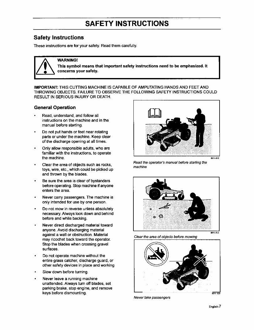
Safety Instructions
These instructionsare for your safety, Read them carefully.
WARNINGI
This symbol means that important safety instructions need to be emphasized. Itconcerns your safety.
IMPORTANT: THIS CUFFING MACHINE iS CAPABLE OF AMPUTATING HANDS AND FEET ANDTHROWING OBJECTS. FAILURE TO OBSERVE THE FOLLOWING SAFETY INSTRUCTIONS COULDRESULT IN SERIOUS INJURY OR DEATH.
IGeneral Operation
Read, understand, and follow allinstructions on the machine and in themanual before starting.
Do not put hands or feet near rotatingparts or under the machine. Keep clearof the discharge opening at aUtimes.
Only allow responsible adults, who arefamiliar with the instructions, to operatethe machine.
Clear the area of objects such as rocks,toys, wire, etc., which could be picked upand thrown by the blades.
Be sure the area is clear of bystandersbefore operating. Stop machine if anyoneenters the area.
Never carry passengers. The machine isonly intended for use by one person.
Do not mow in reverse unless absolutelynecessary. Always look down and behindbefore and while backing.
Never direct discharged material towardanyone. Avoid discharging materialagainst a wall or obstruction. Materielmay ricochet back toward the operator.Stop the blades when crossing gravelsurfaces.
Do not operate machine without theentire grass catcher, discharge guard, orother safety devices in place and working
Slow down before turning.
Never leave a running machineunattended. Always turn off blades, setparking brake, stop engine, and removekeys before dismounting.
8011 512
Read the operator's manualbefore startingthemachine
80H-513
Clear the area of objects before mowing
Never take passengers
8011_520
English-7
SAFETY INSTRUCTIONS
Disengage blades when not mowing.Shut off engine and wait for all parts tocome to a complete stop before cleaningthe machine, removingthe grasscatcher, or uncloggingthe dischargeguard.
Operate machine only indaylightor goodartificial light.
Do notoperate the machinewhile underthe influenceof alcohol or drugs.
Watch for trafficwhen operating near orcrossing roadways.
Use extra care when loadingorunloading the machine into a trailer ortruck.
Always wear eye protection whenoperating machine.
Data indicates that operators,age 60years and above, are involvedin a largepercentage of ridingmower-relatedinjudes.These operators shouldevaluate their ability to operate the ridingmower safely enough to protectthemselves and others from seriousinjury.
Followthe manufacturer'srecommendationfor wheel weights orcounterweights.
Never allow childrenorother personsnottrained in the use of the machine to useor serviceit. Locallaws may regulate theage of the user. Anyone who operatesthis machine should firstread andunderstand this Operator's Manual.
Keep machine free of grass, leaves orother debrisbuild-upwhichcan touch hotexhaust / engine partsand burn. Do notallow the mower deck to plow leaves orother debris which can cause build-uptooccur.Clean any oil or fuel spillagebefore operatingor storingthe machine.Allow machine to cool before storage.
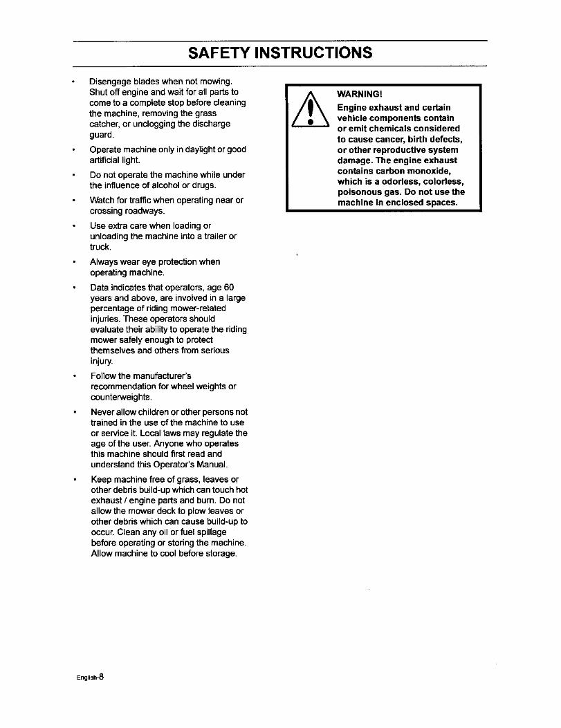
WARNING!
Engine exhaust and certainvehicle components containor emit chemicals consideredto cause cancer, birth defects,or other reproductive systemdamage, The engine exhaustcontains carbon monoxide,which is a odorless, colorless,poisonous gas, Do not use themachine in enclosed spaces,
English-8
SAFETY INSTRUCTIONS
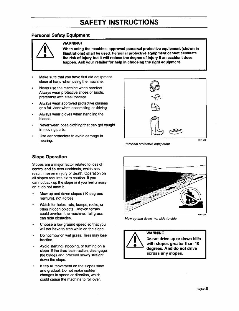
Personal Safety Equipment
WARNING!
When using the machine, approved personal protective equipment (shown inillustrations) shall be used. Personal protective equipment cannot eliminatethe risk of injury but it will reduce the degree of injury if an accident doeshappen. Ask your retailer for help in choosing the right equipment.
Make sure that you have firstaid equipmentclose at hand when using the machine.
Never use the machine when barefoot.Always wear protectiveshoes or boots,preferably with steel toecaps.
Always wear approved protectiveglassesor a full visor when assembling or driving.
Always wear gloveswhen handlingtheblades.
Never wear loose clothingthat can get caughtin movingparts.
Use ear protectorsto avoid damage tohearing.
%
B011_70
Personalprotectiveequipment
Slope Operation
Slopes are a major factor related to lossofcontroland tip-over accidents,which canresult in severe injuryor death. Operation onall slopes requires extra caution, If youcannot back upthe slope or ifyoufeel uneasyon it, do not mow it.
Mow up and down slopes (10 degreesmaxium), notacross.
Watch for holes, ruts, bumps, recks,orother hidden objects. Uneven terraincould overturnthe machine.Tall grasscan hide obstacles.
Choose a low groundspeed so that youwill not have to stop while on the slope.
Do notmow onwet grass. Tires may losetraction.
Avoid starting, stopping,or turningon aslope. If the tireslosetraction,disengagethe blades and proceed slowly straightdown the slope.
Keep all movement on the slopes slowand gradual. Do not make suddenchanges in speed or direction,whichcould cause the machine to rollover.
Mow up and down, not side-to-side
60C_004
WARNING!
Do not drive up or down hillswith slopes greater than 10degrees. And do not driveacross any slopes.
English-9
SAFETY INSTRUCTIONS
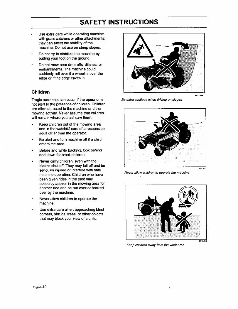
Use extra care while operating machinewithgrass catchersor other attachments;they can affectthe stabilityof themachine. Do not use on steep slopes.
Do nottry to stabilize the machine byputting your foot on the ground.
Do not mow near drop-offs, ditches, orembankments. The machine couldsuddenlyroll over if a wheel is over theedge or if the edge caves in.
Children
Tragic accidents can occur if the operator isnot alert to the presence of children. Childrenare often attracted to the machine and themowing activity.Never assume that childrenwill remain where you last saw them.
Keep childrenout of the mowing areaand inthe watchful care of a responsibleadult other than the operator.
Be alert and turn machine off if a childenters the area.
Before and while backing, look behindand down for smallchildren.
Never carry children, even with theblades shutoff. They may fall off and beseriouslyinjuredor interfere with safemachine operation. Childrenwho havebeen given rides inthe past maysuddenly appear in the mowing area foranother ride and be run over or backedover by the machine.
Never allow childrento operate themachine.
Use extra care when approachingblindcorners, shrubs, trees, or other objectsthat may block your view of a child.
8011-519
Be extra cautious when driving on slopes
8011_517
Neverallow childrento operate the machine
Keep children away from the work area
coil-st8
English-10

SAFETY INSTRUCTIONS
Maintenance
WARNING!
The engine must not be started when the driver's floor plate or any protective platefor the mower deck's drive belt is removed,
Safe Handling of Gasoline
To avoid personal injury or propertydamage,use extreme care in handling gasoline.Gasoline is extremely flammable and thevapors are explosive.
Extinguishall cigarettes,cigars, pipes,and other sources of ignition.
Use only approved gasoline container.
Never remove gas cap or add fuel withthe engine running.Allowengine to coolat least two (2) minutes before refueling.
Never fuel the machine indoors.
Never store the machine or fuelcontainer where there is an open flame,spark, or pilot lightsuch as on a waterheater or other appliances.
Never fill containers insidea vehicle oron a truck or trailer bed with plastic liner.Always place containerson the groundaway from your vehicle when filling.
Remove gas-powered equipment fromthe truck or trailer and refuel it on theground. If this is not possible, then refuelsuchequipment with a portablecontainer,rather than from a gasolinedispenser nozzle.
Keep the nozzle in contactwiththe rimofthe fuel tank or containeropening at alltimes untilfueling is complete. Do notuse a nozzle lock-open device.
If fuel is spilledon clothing,changeclothingimmediately.
Never overfillfuel tank. Replace gas capand tighten securely.
Do not start the engine near spilled fuel.
Never use gasoline as a cleaning agent.
If leaks arise inthe fuel system, theengine must not be started until theproblem has been resolved.
Check the fuel level before each use andleave space forthe fuel to expand,because the heat from the engine and
Never fill the fuel tank indoors
WARNING!
The engine and the exhaustsystem, become very hot duringoperation.Risk for burns if touched.
Allow engine and exhaustsystem to cool at least two (2)minutes before refueling
I
English-11
SAFETY INSTRUCTIONS
the sun may otherwise cause the fuel toexpand and overflow.
General Maintenance
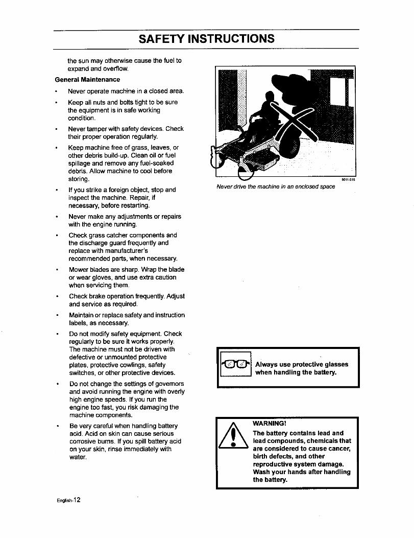
Never operate machine in a closed area.
Keep all nuts and bolts tightto be surethe equipment is in safe workingcondition.
Never tamperwith safety devices. Checktheir proper operationregularly.
Keep machine free of grass, leaves, orother debris build-up. Clean oil or fuelspillage and remove any fuel-soakeddebris. Allow machine to cool beforestoring.
If you strike a foreign object, stop andinspectthe machine. Repair, ifnecessary, before restarting.
Never make any adjustmentsor repairswith the engine running.
Check grass catcher components andthe discharge guard frequently andreplace with manufacturer'srecommended parts, when necessary.
Mower blades are sharp. Wrap the bladeor wear gloves, and usa extra cautionwhen servicingthem.
Check brake operationfrequently. Adjustand service as required.
Maintain or replace safety and instructionlabels, as necessary.
Do not modify safetyequipment. Checkregularly to be sure it works properly.The machine must not be drivenwithdefective or unmountedprotectiveplates, protectivecowlings, safetyswitches, or other protectivedevices.
Do not change the settingsof governorsand avoid running the engine with ovedyhigh engine speeds. If you run theengine too fast, you risk damaging themachine components.
Be very careful when handling batteryacid. Acid on skincan cause seriouscorrosive bums. If you spillbattery acidon your skin, rinse immediatelywithwater.
Never drive the machine in an enclosed space
Always use protective glasseswhen handling the battery.
WARNING!
The battery contains lead andlead compounds, chemicals thatare considered to cause cancer,birth defects, and otherreproductive system damage.Wash your hands after handlingthe battery.
I
English-12
SAFETY INSTRUCTIONS
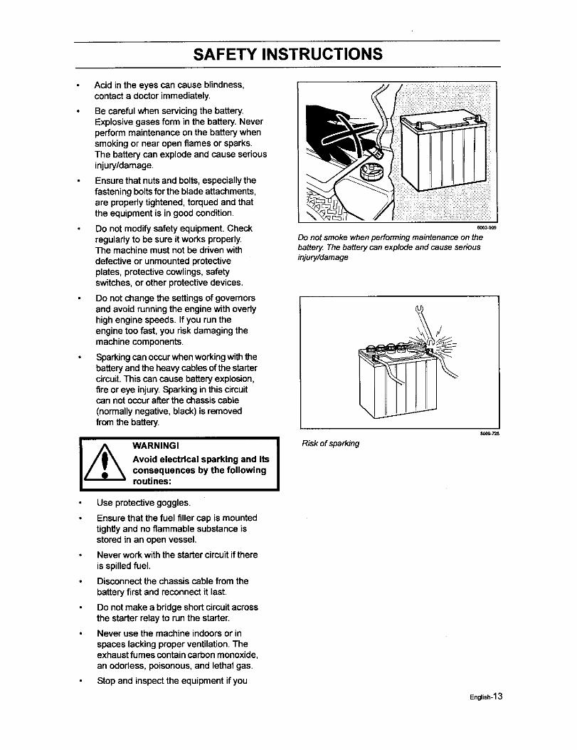
Acid in the eyes can cause blindness,contact a doctor immediately.
Be careful when servicingthe battery.Explosive gases form in the battery. Neverperform maintenance on the battery whensmoking or near open flames or sparks.The battery can explode and cause seriousinjury/damage.
Ensure that nutsand bolts, especiallythefastening bolts for the blade attachments,are propedy tightened, torqued and thatthe equipment is in good condition.
Do not modify safety equipment. Checkregulady to be sure it works properly.The machine must not be driven withdefective or unmounted protectiveplates, protective cowlings, safetyswitches, or other protective devices.
Do not change the settingsof governorsand avoid runningthe engine with ovedyhigh engine speeds. If you run theengine too fast, you risk damaging themachine components.
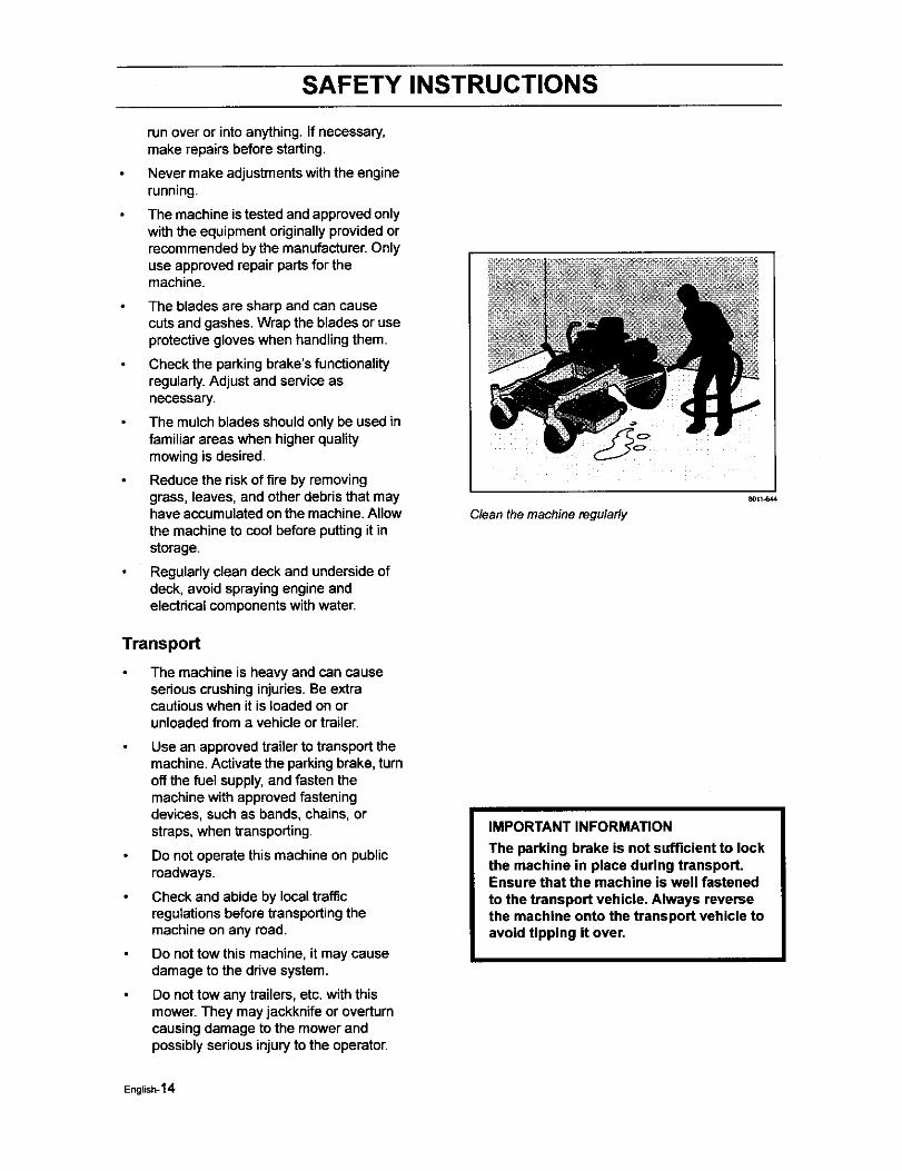
Sparkingcan occurwhen workingwith thebattery and the heavy cables ofthe startercircuit.This can cause batteryexplosion,fire or eye injury.Sparkingin this circuitcan not occurafter the chassiscable(normallynegative,black) is removedfi'om the battery.
I_ ARNING!
Avoid electrical sparking and itsconsequences by the followingroutines:
Use protectivegoggles.
Ensure that the fuel filler cap is mountedtightlyand noflammable substance isstored in an open vessel.
Never work with the starter circuitif thereis spilledfuel.
Disconnectthe chassis cable fTomthebattery firstand reconnect it last.
Do notmake a bridge short circuitacrossthe starter relay to run the starter.
Never use the machine indoorsor inspaces lacking proper ventilation.Theexhaustfumes containcarbon monoxide,an ododess, poisonous,and lethal gas.
Stopand inspect the equipment if you
6003_09
Do not smokewhenperformingmaintenanceon thebattery Thebatterycan explode andcauseseriousinjury/damage
I Risk of sparking
800_7Z8
English-13
SAFETY INSTRUCTIONS
run over or intoanything. If necessary,make repairs before starting.
Never make adjustments with the enginerunning.
The machine is tested and approved onlywith the equipment originally provided orrecommended by the manufacturer. Onlyuse approved repairpartsfor themachine.
The blades are sharp and can causecuts and gashes. Wrap the blades oruseprotectivegloves when handlingthem.
Check the parking brake's functionalityregularly.Adjust and serviceasnecessary.
The mulchblades shouldonly be used infamiliar areas when higher qualitymowingis desired.
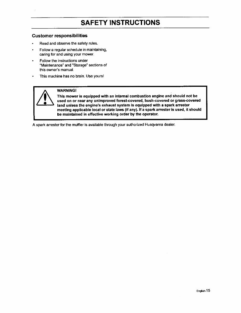
Reduce the riskof fire by removinggrass, leaves, and other debris that mayhave accumulatedonthe machine.Allowthe machine to cool before putting it instorage.
Regularlyclean deck and undersideofdeck, avoid spraying engine andelectdcal componentswithwater.
Transport
The machine is heavy and can causesedous crushinginjuries.Be extracautiouswhen it is loaded on orunloaded froma vehicle or trailer.
Use an approved trailer to transportthemachine.Activate the parking brake, turnoff the fuel supply,and fasten themachine with approved fasteningdevices, such as bands, chains,orstraps, when transporting.
Do not operate this machine on publicroadways.
Check and abide by localtrafficregulations before transporting themachine on any road.
Do not tow this machine, it may causedamage to the drive system.
Do nottow any trailers, etc. withthismower. They may jackknife or overtumcausingdamage to the mower andpossiblyseriousinjury to the operator.
C/ean the machine regularly
80_1_44
IMPORTANT INFORMATION
The parking brake is not sufficient to lockthe machine in place during transport.Ensure that the machine is well fastenedto the transport vehicle. Always reversethe machine onto the transport vehicle toavoid tipping it over.
English-14
SAFETY INSTRUCTIONS
Customer responsibilities
Read and observe the safety rules.
Follow a regular schedule in maintaining,caring for and using your mower.
Follow the instructions under"Maintenance" and "Storage" sections ofthis owner's manual.
This machine has no brain• Use yours!
WARNING!
This mower is equipped with an internal combustion engine and should not beused on or near any unimproved forest-covered, bush-covered or grass-coveredland unless the engine's exhaust system is equipped with a spark arrestermeeting applicable local or state laws (if any). If a spark arrester is used, it shouldbe maintained in effective working order by the operator.
A spark arrester for the muffleris available through your authodzed Husqvama dealer.
English-15
CONTROLS
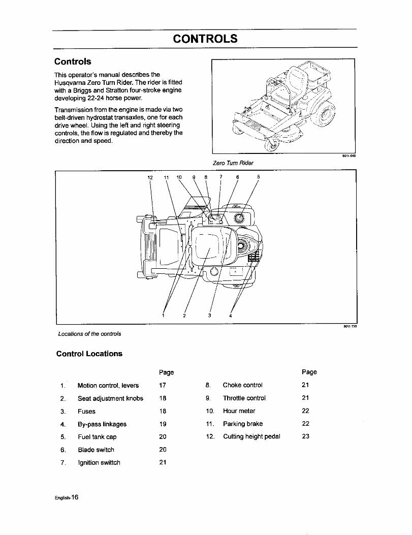
Controls
This operator's manual describes theHusqvarna Zero Turn Rider.The rider is fittedwith a Briggs and Stratton four-stroke enginedeveloping 22-24 horse power.
Transmissionfrom the engine is made via twobelt-driven hydrostat transaxles, one for eachdrive wheel. Using the lef_and right steeringcontrols, the flow is regulated and thereby thedirection and speed.
Zero Turn Rider
12 11 10 9 8 7 6 5
801t_48
1 2 3 4
Locations of the controls
8011735
Control Locations
1. Motion control, levers
2. Seat adjustment knobs
3. Fuses
4. By-pass linkages
5. Fuel tank cap
6. Blade switch
7. Ignition swittch
Page
17
18
18
19
20
20
21
8. Choke control
9. Throttle control
10. Hour meter
11. Parking brake
12. Cuttingheight pedal
Page
21
21
22
22
23
English-16
CONTROLS
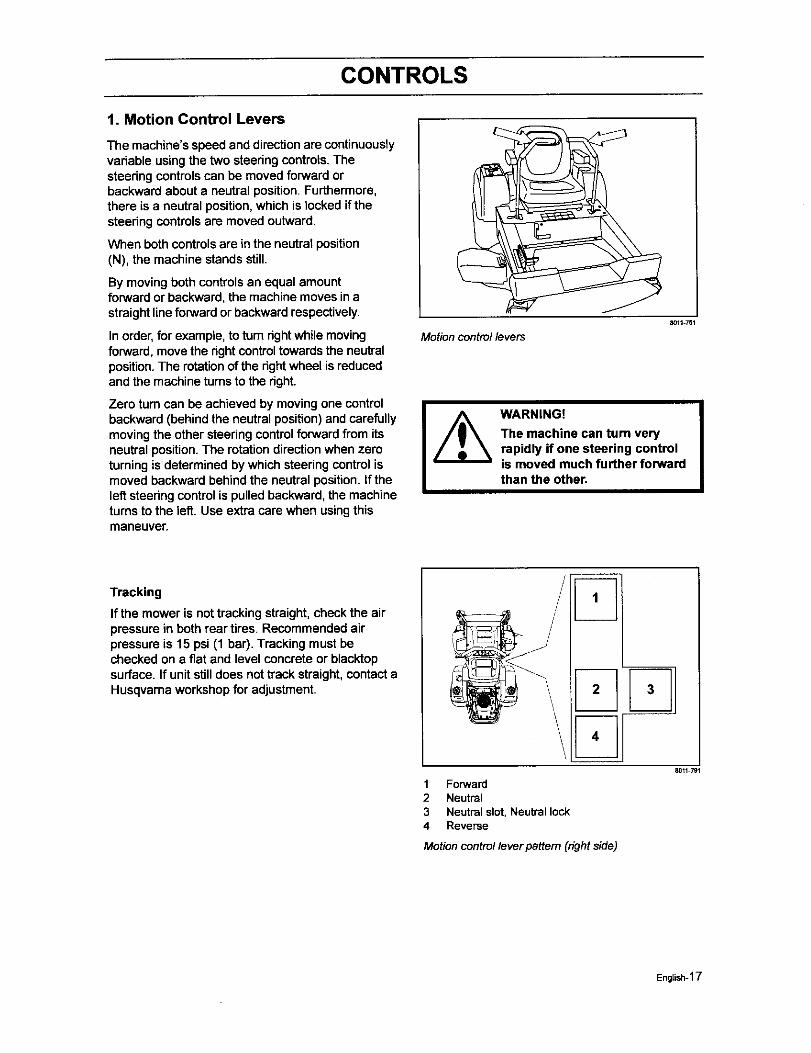
t. Motion Control Levers
The machine's speed and direction are continuouslyvariable usingthe two steeringcontrols. Thesteeringcontrolscan be moved forwardorbackward about a neutral position.Furthermore,there is a neutral position,which is locked if thesteedng controls are moved outward.
When both controlsare in the neutral position(N), the machine stands still.
By movingboth controlsan equal amountforward or backward, the machine moves inastraight line forward or backward respectively.
In order,for example, to turn dght while movingforward, move the dght controltowards the neutralposition.The rotationof the dght wheel is reducedand the machine turnsto the dght.
Zero turn can be achieved by moving one controlbackward (behind the neutral position) and carefullymoving the other steering control forward from itsneutral position. The rotation direction when zeroturning is determined by which steering control ismoved backward behind the neutral position. If theleft steering control is pulled backward, the machineturns to the left. Use extra care when using thismaneuver
Motion control levers8011351
WARNING!
The machine can turn veryrapidly if one steering controlis moved much further forwardthan the other,
Tracking
If the mower is nottrackingstraight, check the airpressure in both rear tires. Recommended airpressure is 15 psi (1 bar). Tracking must bechecked on a flat and level concrete or blacktopsurface. If unit still does not track straight, contact aHusqvarna workshop for adjustment. 2 3
4
1 Forward2 Neutral3 Neutral slot, Neutral lock4 Reverse
Motion control lever pattem (rightside)
8011 791
English-17
CONTROLS
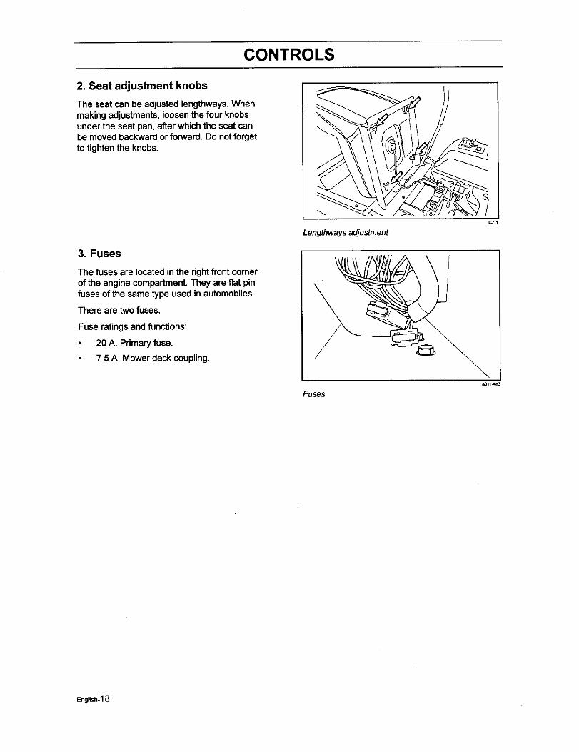
2. Seat adjustment knobs
The seat can be adjusted lengthways. Whenmaking adjustments, loosen the four knobsunder the seat pan, after which the seat canbe moved backward or forward. Do not forgetto tighten the knobs.
3. Fuses
The fuses are located in the rightfront cornerof the engine compartment.They are fiat pinfuses of the same type used in automobiles.
There are two fuses.
Fuse ratings and functions:
20 A, Primary fuse.
7.5 A, Mower deck coupling.
CZ1
Lengthwaysadjustment
Fuses8011 J_3
English-18
CONTROLS
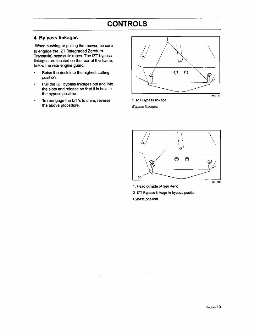
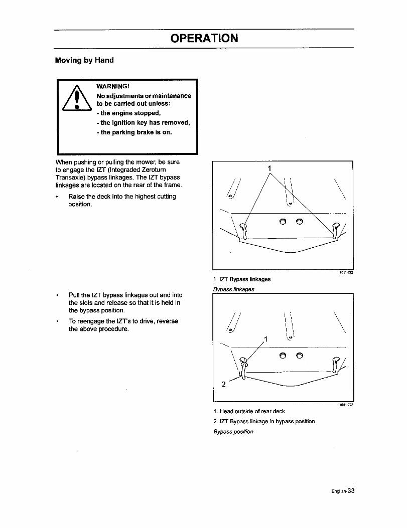
4. By pass linkages
When pushing or pulling the mower, be sureto engage the IZT (Integraded ZerotumTransaxle) bypass linkages. The IZT bypasslinkages are located on the rear of the frame,below the rear engine guard.
Raise the deck into the highest cuttingposition.
Pull the IZT bypass linkages out and intothe slotsand release so that it is held inthe bypass position.
To reengage the IZ'l"s to drive, reversethe above procedure.
1. IZT Bypass linkage
Bypass linkages
\
8011-721
\
2
1. Headoutsideof reardeck
2. IZT Bypasslinkageinbypassposition
Bypassposition
801t 722
English-1 g
CONTROLS
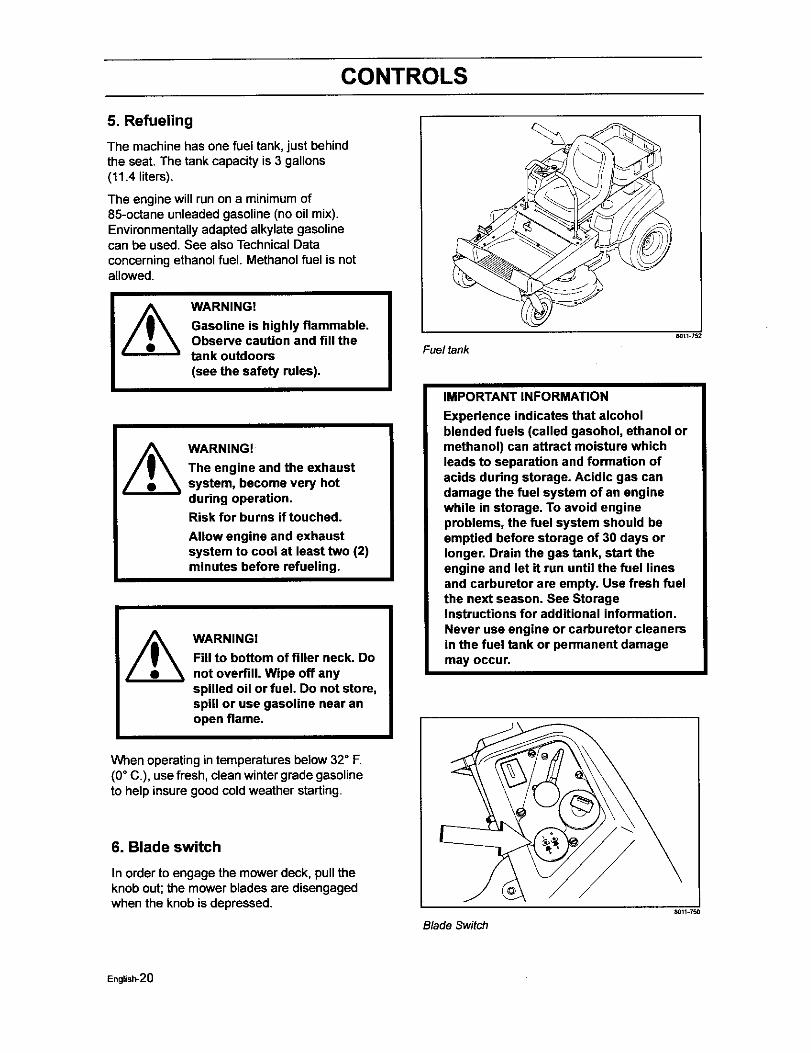
5. Refueling
The machine has one fuel tank, just behindthe seat. The tank capacity is 3 gallons(11.4 liters).
The engine will run on a minimum of85-octane unleaded gasoline (no oil mix).Environmentally adapted alkylate gasolinecan be used. See also Technical Dataconcerning ethanol fuel. Methanol fuel is notallowed.
WARNING!
Gasoline is highly flammable.Observe caution and fill thetank outdoors(see the safety rules).
WARNING!
The engine and the exhaustsystem, become very hotduring operation.Risk for burns if touched.
Allow engine and exhaustsystem to cool at least two (2)minutes before refueling.
WARNING!
Fill to bottom of filler neck. Donot overfill. Wipe off anyspilled oil or fuel. Do not store,spill or use gasoline near anopen flame.
When operating in temperatures below 32° F.(0° C.), use fresh, clean winter grade gasolineto help insure goodcold weather starting.
6. Blade switch
In order to engage the mower deck, pull theknob out; the mower blades are disengagedwhen the knob is depressed.
Fuel tank_117_
IMPORTANT INFORMATION
Experience indicates that alcoholblended fuels (called gasohol, ethanol ormethanol) can attract moisture whichleads to separation and formation ofacids during storage. Acidic gas candamage the fuel system of an enginewhile in storage. To avoid engineproblems, the fuel system should beemptied before storage of 30 days orlonger. Drain the gas tank, start theengine and let it run until the fuel linesand carburetor are empty. Use fresh fuelthe next season. See StorageInstructions for additional information.Never use engine or carburetor cleanersin the fuel tank or permanent damagemay occur.
Blade Switch_117_
English-20
CONTROLS
7. Ignition Switch
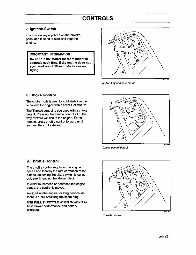
The ignitionkey is placed on the driver'spanel and is used to start and stoptheengine.
IMPORTANT INFORMATION
Do not run the starter for more than fiveseconds each time. If the engine does notstart, wait about 10 seconds before re-trying.
Ignition key and hour meter
11011.748
8. Choke Control
The choke mode is used for coldstartsin orderto providethe enginewitha richerfuel mixture.
The Throttle controlis equippedwith a chokedetent. Pressing the throttle control all of theway forward will choke the engine. For fullthrottle, press throttlecontrolforward untilyou feel the choke detent.
Choke control detent8011480
9. Throttle Control
The throttle controlregulates the enginespeed and thereby the rate of rotation of theblades, assumingthe blade switchis pulledout, see Engaging the Mower Deck.
In order to increase or decrease the enginespeed, the controlis moved.
Avoid idling the engine for long periods, asthere is a risk of fouling the spark plug.
USE FULL THROTTLE WHEN MOWING, forbest mower performance and batterycharging.
Throttle control8011 747
English-21
CONTROLS
10. Hour Meter
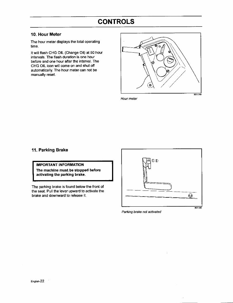
The hour meter displays the total operatingtime.
It will flash CHG OIL (Change Oil) at 50 hourintervals. The flash duration is one hourbefore and one hour after the interval. TheCHG OIL icon will come on and shut offautomatically. The hour meter can not bemanually reset.
Hour meterB011=749
11. Parking Brake
IIMPORTANT INFORMATION
The machine must be stopped beforeactivating the parking brake. I
The parking brake is found be!ow the front ofthe seat. Pull the lever upward to activate thebrake and downward to release it.
Parking brake not activated
English-22
CONTROLS
12. Cutting height pedal
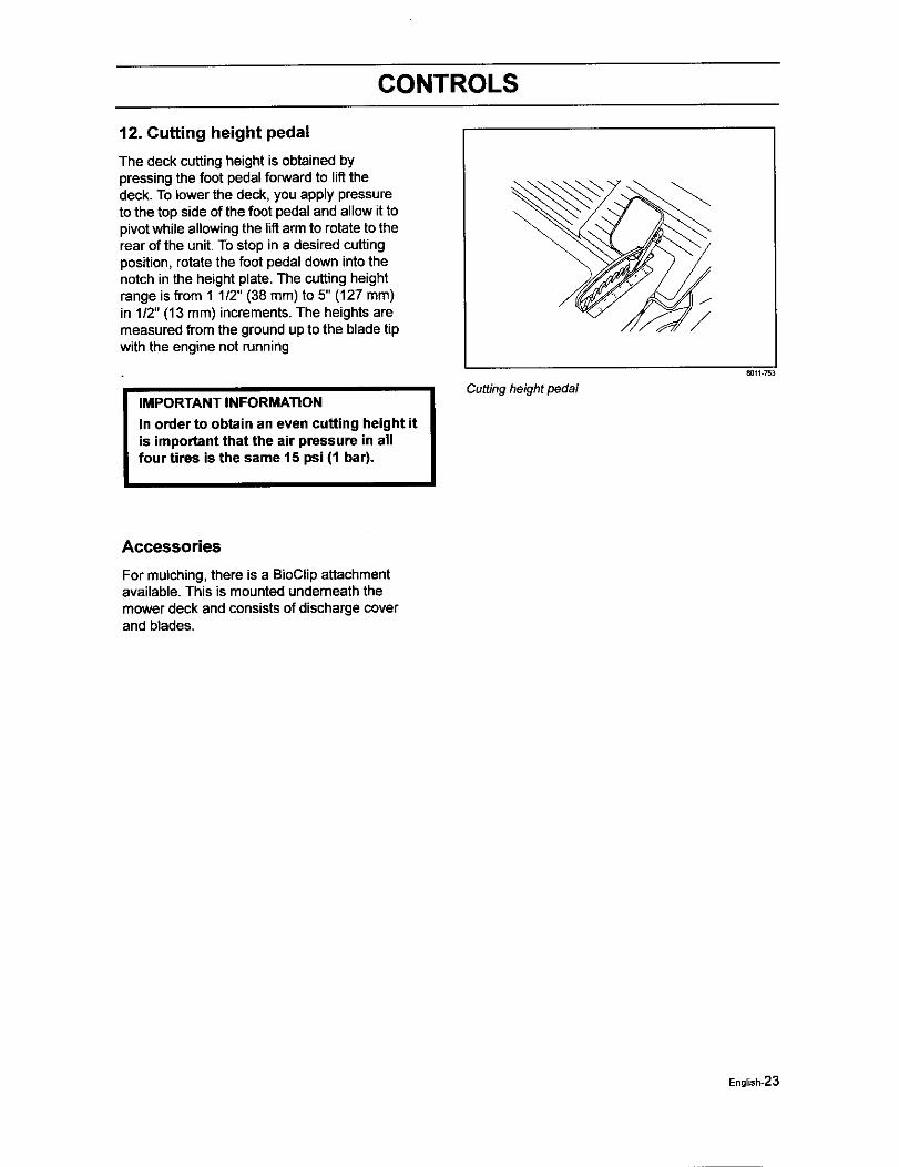
The deck cuttingheight is obtained bypressing the foot pedal forward to lif_thedeck. To lower the deck, you apply pressureto the top side of the foot pedal and allow it topivot while allowing the liftarm to rotate to therear of the unit. To stop in e desired cuttingposition, rotate the foot pedal down into thenotch in the height plate. The cutting heightrange is from 1 1/2" (38 ram) to 5" (127 mm)in 1/2" (13 m m) increments. The heights aremeasured from the ground up to the blade tipwith the engine not running
I MPORTANT INFORMATION
In order to obtain an even cutting height itis important that the air pressure in allfour tires is the same 15 psi (1 bar).
Cutting height pedal
_011-753
Accessories
For mulching, there is a BioClip attachmentavailable. This is mounted undemeath themower deck and consists of discharge coverand blades.
English-23
OPERATION
Operation
Read "Safety Instructions"section and followingpages, if you are unfamiliarwith the machine.
Training
Zero tum mowers are far more manueverable than typical riding mowers due to their unique steeringcapabilities.
We suggestwhen firstoperating the mower, use a reduced throttlespeed and reduced groundspeed byNOT movingcontrollevers to the furthest forwardor reverse positionsduring initialoperation,or untiloperator becomes comfortablewith controls.We also suggest first time users, or new usersto ZeroTummowers to become familiar with the mowers movementon a hard surface, suchas concrete or blacktopPRIOR to attemptingto operate on turf. Until operator becomes comfortable with mower controlsand zeroturningcapability,they may damage turfdue to over aggressivemaneuvers.
To move forward and backward
The direction and speed of the mowers movements is effected by the movement of the control lever(s) oneach side of mower. The left controllever controlsthe leRwheel. The rightcontrollever controls the rightwheel.
IMPORTANT INFORMATION
When control levers are in the reverseposition they return to neutral whenreleased, This may cause the mower tosuddenly stop.
First time users shouldpush mower (see "Moving by Hand" in the "Operation" section)to an open, fiat area,withoutother people orvehicles/obstaclesnear by. In order to move unit under itsown power, the operatormust be inthe seat, start engine (see "Before Starting"in "Operation" section), adjustengine speed to idle,disengage parking brake, do not engage blades at this time, rotate control levers inward.As long as thecontrol levers have not been moved forward or backwards, mowerwill not move. Slowly move both controllevers forward slightly,thiswill allow mowerto start movingforward in a straight line. Pull back on controlleversto the neutral positionand mower should stop moving. Pull back slightlyon control levers, thiswillallow mower to start moving backwards.Push forward on control levers to the neutral positionand mowershouldstop moving.
To turn to the right
While moving in a forward direction, pull the right lever back towards the neutralpositionwhile maintainingthe positionof the left lever, thiswill slow the rotationof the rightwheel and cause the machineto turn inthat direction.
To turn to the left
While moving in a forward direction pull the left lever back towards the neutral position while maintainingthe position of the right lever, this will slow the rotation of the left wheel and cause the machine to turn inthat direction.
To zero turn
While moving in a forward direction,firstpull bothcontrol levers back until the mower stopsor slowsdramatically.Then by alternatingone lever slightlyto the forward positionand the other in the reverseposition.
English*24
OPERATION
Before Starting
Read the sections Safety Instructionsand Controls before startingthemachine.
Perform the daily maintenance beforestarting(see Maintenance Schedulein the Maintenance section).
Check that there is sufficient fuel in thefuel tank.
Adjust the seat to the desired position.
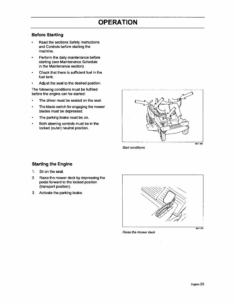
The following conditions must be fulfilledbefore the engine can be started:
The driver must be seated on the seat.
The blade switchfor engaging the mowerblades must be depressed.
The parking brake must be on.
Both steeringcontrolsmust be in thelocked (outer) neutral position.
Startconditions_1_484
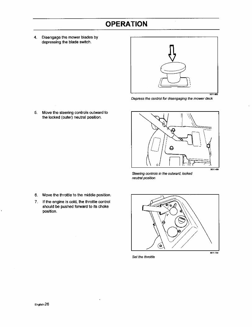
Starting the Engine
1. Sit on the seat.
2. Raise the mower deck by depressingthepedal forwardto the locked position(transport position).
3. Activate the parking brake.
Raise the mower deck8Or1 753
Engtish-25
OPERATION
4. Disengage the mower blades bydepressing the blade switch.
6Q11_68
Depress the control fordisengagingthe mowerdeck
5. Move the steedng controls outward tothe locked (outer) neutral position.
Steedng controlsin the outward, lockedneutral position
8011489
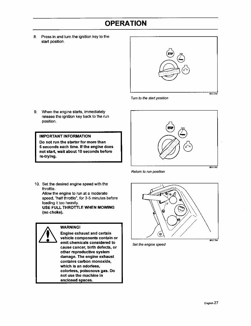
6.
7.
Move the throttle to the middle position.
If the engine is cold, the throttle controlshould be pushed forward to its chokeposition.
Set the throttle80_1754
English-26
OPERATION
8. Press in and turn the ignition key to thestart position.
801_.742
Turnto thestartposition
9. When the engine starts, immediatelyrelease the ignition key back to the runposition.
IMPORTANT INFORMATION
Do not run the starter for more than5 seconds each time. if the engine doesnot start, wait about 10 seconds beforere-trying.
aO11-743
Return torunposition
10. Set the desired engine speed with thethrottle.Allow the engine to run at a moderatespeed, "half throttle",for 3-5 minutes beforeloadingit too heavily.USE FULL THROTTLE WHEN MOWING(no choke).
WARNING!
Engine exhaust and certainvehicle components contain oremit chemicals considered tocause cancer, birth defects, orother reproductive systemdamage. The engine exhaustcontains carbon monoxide,which is an odorless,colorless, poisonous gas. Donot use the machine in
enclosed spaces.
Set the engine speed
8011754
English-27
OPERATION
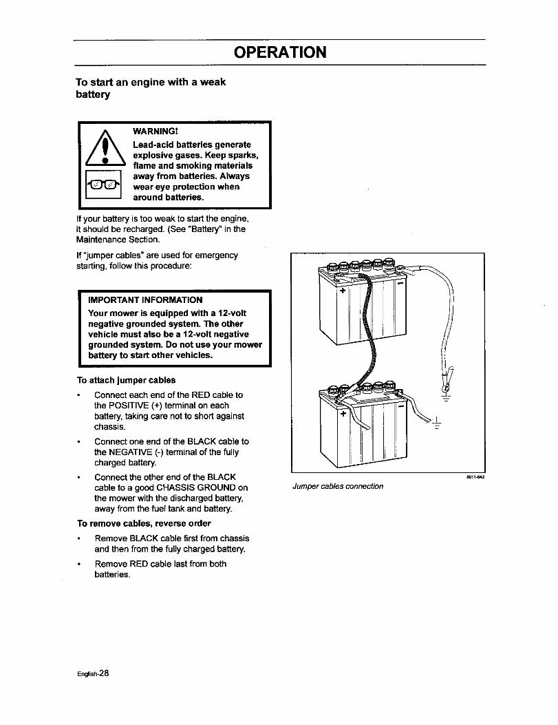
To start an engine with a weakbattery
WARNING!
Lead-acid batteries generateexplosive gases. Keep sparks,flame and smoking materialsaway from batteries. Alwayswear eye protection whenaround batteries.
If your battery is too weak to start the engine,it should be recharged. (See "Battery" in theMaintenance Section.
If "jumper cables" are used for emergencystarting,follow this procedure:
IMPORTANT INFORMATION
Your mower is equipped with a 12-voltnegative grounded system. The othervehicle must also be a 12-volt negativegrounded system. Do not use your mowerbattery to start other vehicles.
To attach jumper cables
Connect each end of the RED cable tothe POSITIVE (+) terminal on eachbattery,taking care notto short againstchassis.
Connect one end of the BLACK cable tothe NEGATIVE (-) terminal of the fullycharged battery.
Connect the other end of the BLACKcable to a good CHASSIS GROUND onthe mower with the discharged battery,away from the fuel tank and battery.
To remove cables, reverse order
Remove BLACK cable first fromchassisand then from the fullycharged battery.
Remove RED cable last from bothbatteries.
Jumper cables connection
8011-642
English-28
OPERATION
Running
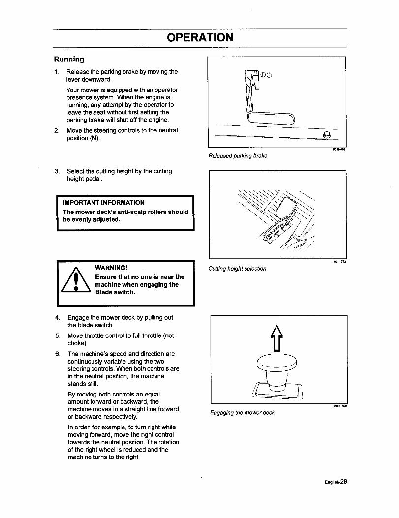
1. Release the parking brake by movingthelever downward.
2.
Your mower is equippedwithan operatorpresence system. When the engine isrunning,any attempt by the operatortoleave the seat without first setting theparking brake will shutoff the engine.
Move the steeringcontrolsto the neutralposition(N).
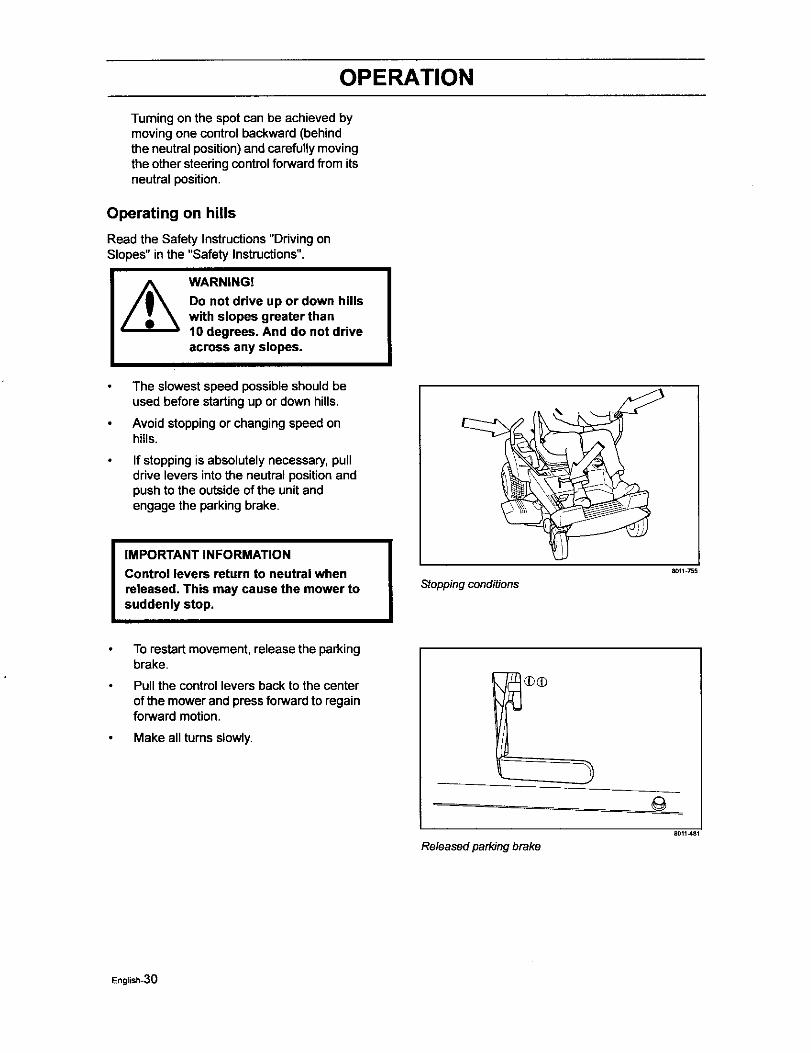
3. Select the cuttingheight by the cuttingheight pedal.
IIMPORTANT INFORMATION
The mower deck's anti-scalp rollers shouldbe evenly adjusted,
8011J_81
Releasedparkingbrake
IWARNINGI
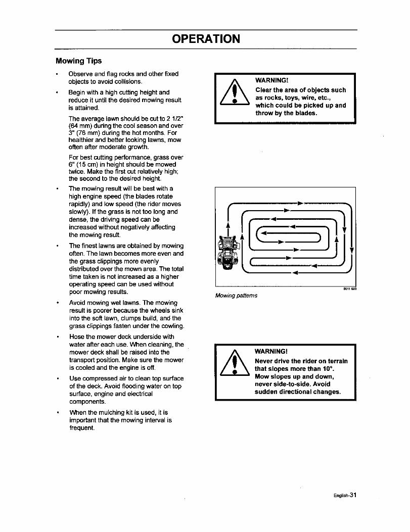
Ensure that no one is near themachine when engaging theBlade switch.
4.
5.
6.
Engage the mower deck by pullingoutthe blade switch.
Move throttle controlto fullthrottle (notchoke)
The machine's speed and directionarecontinuouslyvadable usingthe twosteeringcontrols.When both controlsareinthe neutral position,the machinestandsstill.
By moving both controls an equalamount forward or backward, themachine moves in a straight line forwardor backward respectively.
In order, for example, to turn dght whilemoving forward, move the right controltowards the neutral position. The rotationof the dght wheel is reduced and themachine turns to the right.
Cutting height selection
8011=753
Engaging the mower deck
English-29
OPERATION
Turning on the spotcan be achieved bymoving one control backward (behindthe neutral position) and carefully movingthe other steering control forward from itsneutral position.
Operating on hills
Read the Safety Instructions"Driving onSlopes" inthe "Safety Instructions".
WARNING!
Do not drive up or down hillswith slopes greater than10 degrees. And do not driveacross any slopes.
The slowestspeed possible should beused before startingup or down hills.
Avoid stoppingor changingspeed onhills.
If stoppingis absolutely necessary, pulldrive levers into the neutral position andpush to the outsideof the unitandengage the parking brake.
I IMPORTANT INFORMATION
Control levers return to neutral whenreleased, This may cause the mower tosuddenly stop.
To restart movement, release the parkingbrake.
Pull the control levers back to the centerof the mower and press forward to regainforward motion.
Make all turns slowly.
Stopping conditions
8011 755
Released parking brake
English-3O
OPERATION
Mowing Tips
Observe and flag rocks and other fixedobjectsto avoid collisions.
Begin with a highcuttingheightandreduce it until the desired mowingresultis attained.
The average lawn shouldbe cutto 2 1/2"(64 mm) during the cool season and over3" (76 mm) during the hot months.Forhealthier and better lookinglawns, mowoften after moderate growth.
For best cuttingperformance,grass over6" (15 cm) in heightshould be mowedtwice. Make the firstcut relativelyhigh;the second to the desired height.
The mowingresult will be best with ahigh engine speed (the blades rotaterapidly) and low speed (the rider movesslowly). If the grass is not too long anddense, the ddving speed can beincreasedwithout negativelyaffectingthe mowingresult.
The finest lawnsare obtained by mowingoften. The lawn becomesmore even andthe grass clippingsmore evenlydistributedoverthe mown area. The totaltime taken is not increased as a higheroperatingspeed can be used withoutpoor mowingresults.
Avoid mowingwet lawns. The mowingresult is poorer because the wheels sinkinto the soft lawn, clumps build,and thegrass clippingsfasten underthe cowling.
Hose the mower deck undersidewith
water after each use. When cleaning,themower deck shall be raised intothetransport position.Make surethe moweris cooled and the engine is off.
Use compressedair to clean top surfaceof the deck. Avoid floodingwater on topsurface, engine and electdcalcomponents.
When the mulchingkit is used, it isimportantthat the mowing interval isfrequent.
Mowing patterns
WARNING!
Clear the area of objects suchas rocks, toys, wire, etc.,which could be picked up andthrow by the blades.
8011_03
WARNING!
Never drive the rider on terrainthat slopes more than 10°.Mow slopes up and down,never side-to-side. Avoidsudden directional changes.
English*31
OPERATION
Stopping the Engine
Allow the engine to idle a minute in ordertoattain normal operating temperature beforestoppingit, if it has been worked hard. Avoididlingthe engine for longer periods, as thereis a riskof the sparkplugs fouling.
1. Disengage the mower deck bydepressing the blade switch.
80t1_
Disengagethe mowerdeck
2. Raise the mower deck by depressing thepedal forwardto the transport position.
3. When the machine is standingstill,activate the parkingbrake by pullingthelever upward.
4. Move the throttleto the minimumposition(tortoisesymbol).Turn the ignitionkeytothe stop position.
5. Move the steeringcontrols outward.
6. Remove key. Always remove key whenleaving the mower to preventunauthorizeduse.
Raise the mower deck with the lifting pedalB011=753
IMPORTANT INFORMATION
Leaving the ignition switch in any otherposition than "OFF" will cause the batteryto be discharged and the hour meter toaccumulate hours.
English-32
OPERATION
Moving by Hand
WARNING!
No adjustments or maintenanceto be carried out unless:
-the engine stopped,
-the ignition key has removed,
- the parking brake is on.
When pushingor pulling the mower, be sureto engage the IZT (Integraded ZeroturnTransaxle) bypass linkages.The IZ'I"bypasslinkages are located on the rear of the frame.
Raise the deck into the highest cuttingposition.
\\
Pull the IZT bypass linkagesout and intothe slotsand release so that it is held inthe bypass position.
To reengage the IZT's to ddve, reversethe above procedure.
1. IZT Bypass linkages
Bypass linkages
80tl
.// \
1. Head outside of rear deck
2. IZT Bypass linkage in bypass position
Bypass position
8011 722
EnglJsh-33
MAINTENANCE
Maintenance
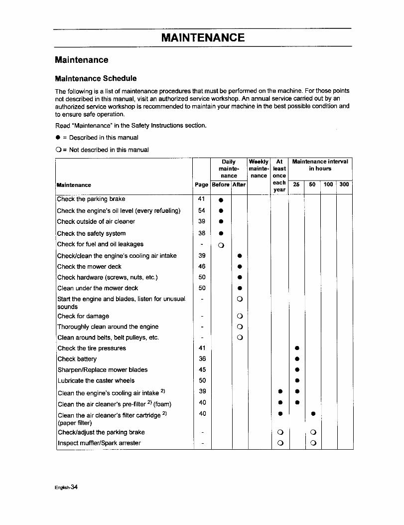
Maintenance Schedule
The following is a list of maintenance procedures that must be performed on the machine. For those pointsnot described in this manual, visit an authorized service workshop. An annual service carried out by anauthorized service workshop is recommended to maintain your machine in the best possible condition andto ensure safe operation.
Read =Maintenance" in the Safety Instructionssection.
• = Described in this manual
C) = Not described in this manual
Maintenance
Check the parking brake
_,heckthe engine's oil level (every refueling)
Check outside of air cleaner
Check the safety system
Check for fuel and oil leakages
Check/clean the engine's cooling air intake
Check the mower deck
Check hardware (screws, nuts, etc.)
Clean under the mower deck
Start the engine and blades, listen for unusualsounds
Check for damage
Thoroughly clean around the engine
Clean around belts, belt pulleys, etc.
Daily Weekly At Maintenanceintervalmainte- mainte- least in hoursnance nance once
Page Before After each 25 50 100 300year
41 •
54 •
39 •
38 •
O
39 •
46 •
50 •
50 •
O
O
O
O
Check the tire pressures
Check battery
Sharpen/Replace mower blades
Lubdcate the caster wheels
41
36
45
5O
Clean the engine's cooling air intake 2)
Clean the air cleaner's pre-filter 2) (foam)
Clean the air cleaner's filter cartridge 2)(paper filter)
Check/adjust the parking brake
Inspect muffler/Sparkattester
39
40
40
• •
0 0
0 0
English-34
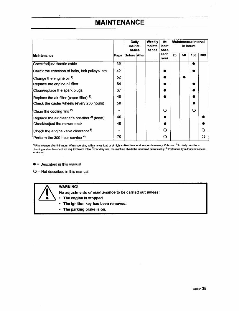
MAINTENANCE
Maintenance Page
Check/adjust throttlecable 39
Check the conditionof belts, belt pulleys,etc. 42
Change the engine oil l) 52
Replace the engine oil filter 54
Clean/replace the spark plugs 37
Replace the air filter (paper filter) 2) 40
Check the caster wheels (every 200 hours) 50
Clean the cooling fins 2)
;Replace the air cleaner's pre-filter2) (foam) 40
Check/adjust the mower deck 46
Check the engine valve clearance4)
Perform the 300-hour service4) 70
Dailymainte- mainte-nance nance
Before After
Weekly At Maintenance intervalleast in hours
once
each 25 50 t00 300year
Q Q
o Q
Q Q
!) First change after 5-8 hours. When operating with a heavy load or at high ambient temperatures, replace every 50 hours. 2) In dusty conditions,
c_eaning and rel_acoment are required more often, 3)For daily use, the machine should be lubricated twice weekly, 4)Pedormed by authonzed service
workshop.
• = Described inthis manual
0 = Not described in this manual
]
WARNING!
No adjustments or maintenance to be carried out unless:
• The engine is stopped.
• The ignition key has been removed.
• The parking brake is on.
English-35
MAINTENANCE
Ba_ew
Your mower is equipped with a maintenance freebattery and does not need servicing.However,periodic charging of the battery with an automotivetype battery charger will extend its life.
Keep battery and terminals clean.
Keep battery bolts tight.
Recharge at 6-10 amperes for I hour
To clean battery and terminals
Corrosion and dirt on the battery and
terminals can cause the battery to =leak"power.
1. Open terminal access deers.
2. Disconnect BLACK battery cable first, then the
RED battery cable and remove the battery fromthe machine.
3. Rinse the battery with plain water and dry.
4. Clean terminals and battery cable endswith wire brush until shiny.
5. Coat terminals with grease or petroleum
jelly
6. Reinstall battery.
I Always use protective glasses
when handling the battery.
IMPORTANT INFORMATION
Do not attempt to open or remove capsor covers. Adding or checking level ofelectrolyte is not necessary.
Always use two wrenches for theterminal screws
WARNING!
Do not short battery terminalsby allowing a wrench or anyother object to contact bothterminals at the same time.Before connecting battery,remove metal bracelets,wristwatch bands, rings, etc.Positive terminal must beconnected first to preventsparks from accidentalgrounding.
I
Replacing battery
1: Lif_Seat and rotate forward.
2. Open terminal access doors.
3. Using two 1/2" wrenches disconnect BLACKbattery cable then RED battery cable.
4. Using 7/16" wrench, remove terminal guard.
5. Carefully remove the battery from the mower.
6. Installnew batterywith terminals inthesame positionas the old battery.
7. Reinstallterminal guard.
8. First connect RED batterycable to positive(+)batteryterminal with hex bolt and hex nut.
9. ConnectBLACK groundingcable to negative(-)batteryterminal with remaininghex bolt andhex nut.
10. "nghtensecurely.
11. Close terminalaccess doors.
12. Lower seat.
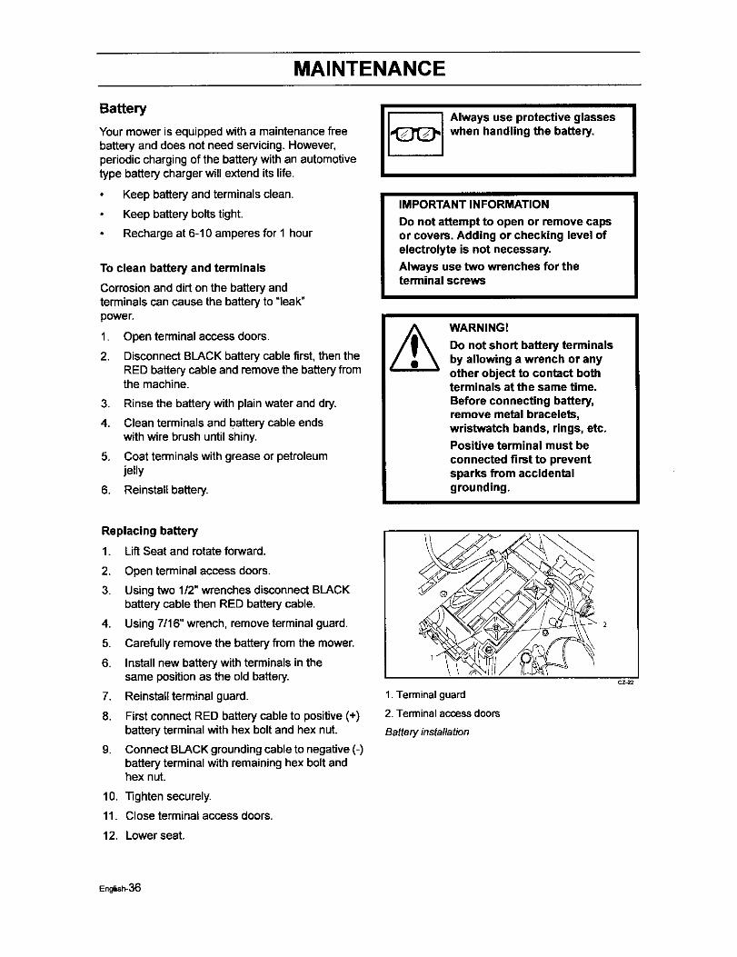
1 .,_
1. Terminal guard
2. Terminal access doors
Battery installation
CZ_2
English-36

MAINTENANCE
Ignition System
The engine is equipped with an electronicignition system. Only the sparkplug requiresmaintenance.
For recommended spark plug, see TechnicalData.
1. Remove the ignition cable boot andclean around the spark plug.
2. Remove the spark plug with a spark plugsocket wrench.
3. Check the spark plug. Replace the sparkplug if fouled, the electrodes are burnedand if the insulation is cracked ordamaged. Clean the spark plug with asteel brush if it is to be reused.
4,
5.
6.
Measure the electrode gap with agapping tool. The gap should be .030"(0.75 mm). Adjust as necessary bybending the side electrode.
Reinsert the spark plug, turningby handto avoid damaging the threads.
After the spark plug is seated, tighten itusing a spark plug wrench so that thewasher is compressed. A used sparkplug should be turned 1/8 of a turn fromthe seated position. A new spark plugshould be turned 1/4 a turn from theseated position.
7. Replace the ignition cable.
IMPORTANT INFORMATION
Fitting the wrong spark plug type candamage the engine.
Inadequately tightened spark plug cancause overheating and damage theengine. Tightening the spark plug toohard can damage the threads in thecylinder head.
0.028-0.031 in
3.70-0.80 mm)
Measure the electrode gap
8011 O54
English-37
MAINTENANCE
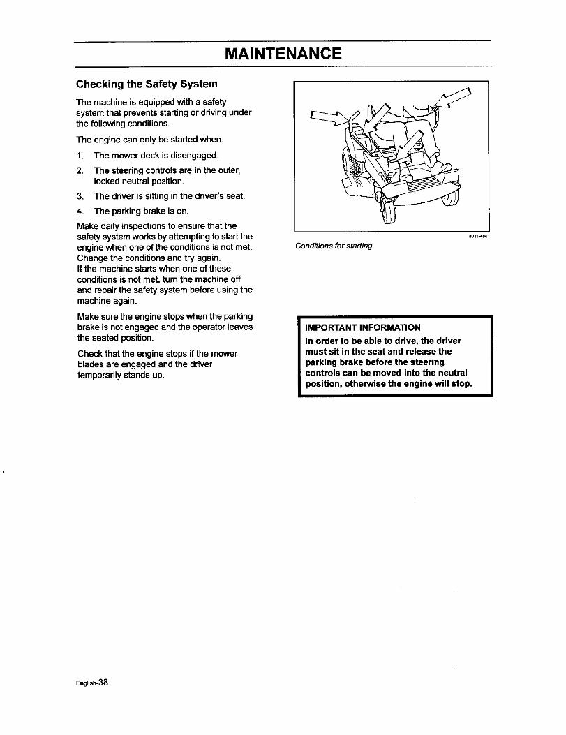
Checking the Safety System
The machine is equipped with a safetysystemthat prevents startingor drivingunderthe following conditions.
The engine can only be startedwhen:
1. The mower deck is disengaged.
2. The steering controlsare in the outer,locked neutral position.
3. The driver is sittingin the driver's seat.
4. The parkingbrake is on.
Make daily inspectionsto ensure that thesafetysystemworks by attemptingto starttheengine when one of the conditionsis not met.Change the conditionsand try again.If the machine startswhen one of theseconditions is not met, tum the machine offand repairthe safety systembefore usingthemachine again.
Make surethe engine stopswhen the parkingbrake is notengaged andthe operator leavesthe seated position.
Check that the engine stopsif the mowerblades are engaged and the drivertemporarilystands up.
Conditions for starting
8011J_4
IMPORTANT INFORMATION
In order to be able to drive, the drivermust sit in the seat and release theparking brake before the steeringcontrols can be moved into the neutralposition, otherwise the engine will stop.
English-38
MAINTENANCE
Checking the Engine's Cooling Air Intake
Check that the engine's coolingair intake isfree from leaves, grass, and dirt.If the cooling air intake is clogged, enginecooling deteriorates, which can lead toengine damage.
Check and clean the cooling air intake801149t
Checking and Adjusting theThrottle Cable
Check that the engine responds to throttleincreases and that a good engine speed isattained at full throttle.If doubts adse, contact tl_e service workshop.If adjustments are necessary, they can bemade as follows for the lower cable:
1. Loosen the clamping screw for thecable's outer casing and move thethrottle to the full throttle position (nochoke).
2. Check that the throttle cable is mountedin the correct hole in the lever, seeillustration.
3. Push the throttle cable's outer casinguntil choke start position, see illustation,and tighten the clamping screw.
4. Set the throttle control to the chokeposition and check that full choke isobtained.
B0114_
Adjustingthethrottle cable
Chokestartposition8009404
English-39
MAINTENANCE
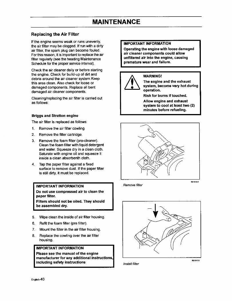
Replacing the Air Filter
If the engine seems weak or runs unevenly,the airfilter may be clogged. If run with a dirtyair filter, the spark plug can become fouled.Forthismason, it is importantto replacethe airfilterregularly(see the heading MaintenanceSchedule for the properservice interval).
Check the air cleaner daily or before startingthe engine. Check for build-up of dirt anddebrisaround the air cleaner system.Keepthis area clean. Also check for loose ordamaged components.Replace all bentdamaged aircleaner components.
Cleaning/replacing the air filteris carded outas follows:
Briggs and Stratton engine
The air filter is replaced as follows:
1. Remove the air filter cowling
2. Remove the filter cartridge.
3. Remove the foam filter (pre-cleaner).Clean the foam filter with liquid detergentand water. Squeeze dry in a clean cloth.Saturate with engine oil and squeeze itinsidea clean absorbenthcloth.
4. Tap the paper filter against a fixedsurfaceto remove dust. If the paper filteris stilldirty,it must be replaced.
IMPORTANT INFORMATION
Do not use compressed air to clean thepaper filter.Filters should not be oiled. They shouldbe assembled dry.
5. Wipe clean the inside of air filter housing.
6. Refit the foam filter (pre filter).
7. Mount the filterin the air filter housing.
8. Replace the cowling over the air filterhousing.
I IMPORTANT INFORMATION I
Please see the manual of the engine |manufacturer for any additional instrucUons, Iincluding safety instructions |
I
IMPORTANT INFORMATION
Operating the engine with loose damagedair cleaner components could allowunfiltered air into the engine, causingpremature wear and failure.
WARNING!
The engine and the exhaustsystem, become very hot duringoperation.Risk for burns if touched.
Allow engine and exhaustsystem to cool at least two (2)minutes before refueling.
Remove filter
Install filter
801_0t4
8019_15
English_0
MAINTENANCE
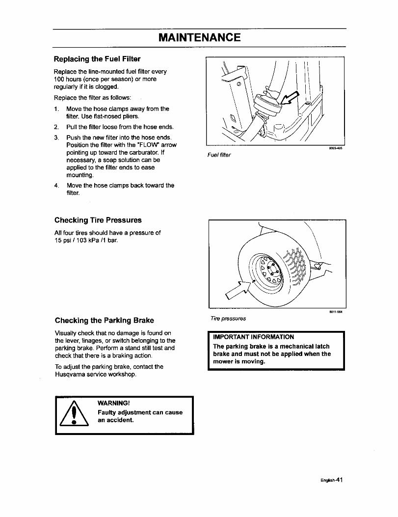
Replacing the Fuel Filter
Replace the line-mounted fuel filter every100 hours (once per season) or moreregularly if it is clogged.
Replace the filter as follows:
1. Move the hose clamps away from thefilter. Use flat-nosed pliers.
2. Pull the filter loose from the hose ends.
3. Push the new filter into the hose ends.Position the filter with the "FLOW" arrowpointing up toward the carburator. Ifnecessary, a soap solution can beapplied to the filter ends to easemounting.
4. Move the hose clamps back toward thefilter.
Fuel filter8009405
Checking Tire Pressures
All four tires shouldhave a pressureof15 psi / 103 kPa/1 bar.
Checking the Parking Brake
Visually check that no damage is found onthe lever, linages, or switch belonging to theparking brake. Perform a stand still test andcheck that there is a braking action.
To adjust the parking brake, contact theHusqvarna service workshop.
Tire pressures
8011_64
I MPORTANT INFORMATION I
The parking brake is a mechanical latchbrake and must not be applied when themower is moving.
WARNING!
Faulty adjustment can causean accident. I
English_l
MAINTENANCE
Checking the V-belts
WARNING!
No adjustments or maintenance to be carried out unless:
• The engine is stopped.
• The ignition key has been removed.
• The parking brake is on,
Deck belt
V-belts are not adjustable. Replace belts if they beginto slipfrom wear.
Deck belt removal
WARNING!
Idler arm is spring loaded. Havea tight grip on idler arm orratchet and release slowly,
Park on a level surface. Apply parkingbrake.
Lower the deck into the lowest cutting
position
Disengage belt tension by pushinginward on deck belt idlerpulley by handor with a 1/2" ddve ratchet placed insquare drive hole on idler arm, While armis pushed inward, remove belt fromstationary idler pulley and release idlerarm slowly until spdng force is no longerfelt.
Remove bolt from idler pulley. This willallow belt to pass by the belt guide.
Loosen screws from both left and dghtplastic belt shield above each mandrelhousing. Remove shields
Remove any dirt or grass that may haveaccumulated around the cutter housingsand entire deck surface.
Carefully roll the belt over the top of thecutter housingpulleys.
Remove the belt from around the electricclutch on the engine shaft.
The belt can now be removed.
English_42
MAINTENANCE
Deck belt installation
NOTE: For ease in installingthe deck belt,refer to the routingdecal on bottom of seat.
Wrap the deck belt around the electdcclutchpulley that is located onthe engineshaft.
Route the belt forward between the EZT(E-Series Zeroturn Transaxles) and uponto the deck.
Place belt around spring loaded idlerpulley, between the pulley and guide.Secure bolt and nut.
Startingon the right hand side of thedeck, wrap the belt around the stationaryidler pulley, the right mandrel housing,then around to the left mandrel housing.
Push inward on the idler arm andcarefully route belt over stationary idlerpulley. Once belt is properly routed,slowly release idler arm to tension belt.
Double check belt routing to make sure itmatches the routing decal, and the beltdoes not have any twist. Correct asneeded.
Replace belt shields on both mandrelhousings and secure with fasteners.
1. Clutch pulley
Belt muting, deck belt
English_3
MAINTENANCE
EZT belt
To replace EZT (E-Series ZeroturnTransaxle) belt
Park the mower on a level surface. Engagethe parking brake.
EZT belt removal
NOTE: Be careful not to damage the tanblades on the EZT's as this can affect coolingor damage the EZT's
Remove the deck belt (see to replacedeck belt in this section of the manual).
Unplug clutch from wiring harness.Remove bolt from center of clutch andslide clutch off of engine shaft.
Create slack in the belt by removing thespdng on the pump idler arm.
The belt should now be able to beremoved from the engine pulley andEZT pulleys.
Belt installation
Wrap the EZT belt around the EZTpulleys
Route the belt around the inside of theidler pulley.
Now you can wrap the belt around theengine pulley.
Reattach the springon the pump idlerarm.
Installclutchon to engine shaft (pulleyside down) make sure key is installedand alignthe clutch anti rotationtab intosloton clutch.Secure clutch, installwire.
Reinstall the deck belt onto the electdcclutch belt (see to replace deck belt inthis section of the manual).
Transaxle belt
English_4
MAINTENANCE
Checking the Blades
In order to attain the best mowing effect, it isimportantthat the blades are well sharpenedand not damaged.
/_ WARNING!Blades are sharp. Protect yourhands with gloves andlor wrapblades with a heavy cloth when
_ handling.
Bent or cracked blades or blades with largenicksshould be replaced.
Check the blade mounts.
Check the blades
801t_04
IMPORTANT INFORMATION
The sharpening of blades should becarried out by an authorized serviceworkshop.
Damaged blades should be replaced whenhittingobstacles that result in a breakdown.Let the service workshop decide whether theblade can be repaired/greund or must bereplaced.
I
Blade replacement:
WARNING!
Blades are sharp. Protect yourhands with gloves andlor wrapblades with a heavy cloth whenhandling.
Remove blade bolt by turningcounterclockwise.
I IMPORTANT INFORMATION
To ensure proper assembly, center hole inblade must align with star on cutterhousing.
4
1
2
1. Blade
2. Center hole
3. Star
4. Cutter housing
5. Blade bait (special)
Blade attachment
8011_71
English-45
MAINTENANCE
Installnew or re-sharpened blade withstamped "GRASS SIDE" facing towardsground/grass (down) or =THIS SIDE UP"facing deck and cutter housing.
Installand tighten blade bolt securely.
Torque blade bolt to 27-35 P,JIb(35-45 Nm).
IMPORTANT INFORMATION
Special blade bolt is heat treated.
Replace with a Husqvarna bolt if required.
Do not use lower grade hardware thanspecified.
Adjusting the Mower Deck
WARNING!
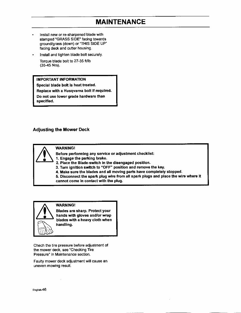
Before performing any service or adjustment checklist:1. Engage the parking brake,2. Place the Blade-switch in the disengaged position.3. Turn ignition switch to "OFF" position and remove the key,4, Make sure the blades and all moving parts have completely stopped.5, Disconnect the spark plug wire from all spark plugs and place the wire where itcannot come in contact with the plug.
WARNING!
Blades are sharp. Protect yourhands with gloves and/or wrapblades with a heavy cloth whenhandling.
Chech the tire pressure before adjustment ofthe mower deck, see "Checking TirePressure" in Maintenance section.
Faulty mower deck adjustmentwill cause anuneven mowing result.
English_6
MAINTENANCE
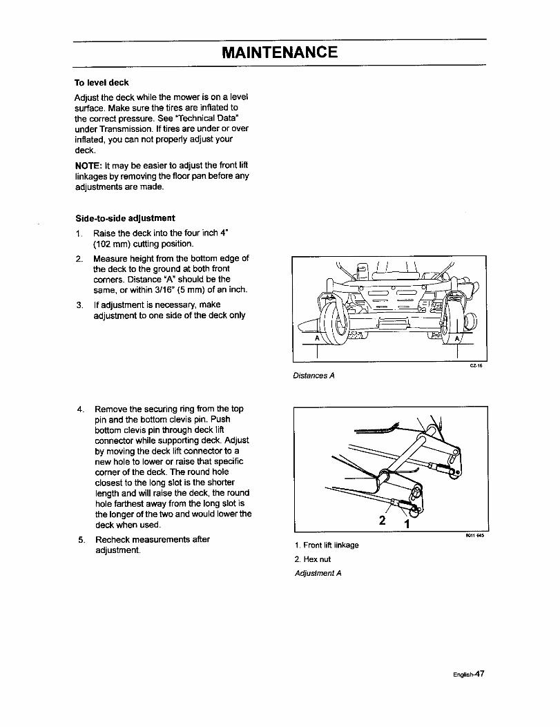
To level deck
Adjustthe deck while the mower is on a levelsurface. Make sure the tiresare inflatedtothe correct pressure. See "Technical Data"underTransmission. Iftires are underor overinflated, you can not propedy adjust yourdeck.
NOTE: It may be easier to adjust the front liftlinkagesby removing the floor pan before anyadjustments are made.
Side-to-side adjustment
1. Raise the deck into the four inch 4"(102 mm) cuttingposition,
2, Measure height from the bottom edge ofthe deck to the groundat both frontcorners. Distance =A" should be thesame, or within 3/16" (5 mm) of an inch.
3. If adjustment is necessary, makeadjustmentto one side of the deck only
Distances A
4.
5,
Remove the securing ring from the toppin and the bottom clevis pin. Pushbottom clevis pin through deck liftconnector while supporting deck. Adjustby moving the deck lift connector to anew hole to lower or raise that specificcorner of the deck. The round holeclosest to the long slot is the shorterlength and will raise the deck, the roundhole farthest away from the longslot isthe longer of the two and wouldlower thedeck when used.
Recheck measurements afteradjustment.
2 1
1. Front lift linkage
2. Hex nut
Adjustment A
8011_a45
Englisi_7
MAINTENANCE
Front-to-back adjustment
IMPORTANT INFORMATION
Deck must be leveled side-to-side, prior toleveling front to back. If the following frontto back adjustment is required, be sure toadjust both front and rear linkages equallyso the deck will stay level side to side.
To obtainthe best cutting performance, thedeck shouldbe adjustedso the fronttip of theblades are approximately 1/8" (3.2 ram) to1/4" (6.5 mm) lower than the rear tip. If thefront tip is higher, this will create a poorquality of cut.
BT
Front to back adjustmentCZ.19
WARNING!
Blades are sharp. Protect yourhands with gloves and/or wrapblades with a heavy cloth whenhandling.
1. Check blade heightwith blade facingfront to rear. Measure distance =B" at thefront and rear tip of the blade.
2. Before making any necessaryadjustments, check to make sure that thedeck is level side-to-side. See "Side toSide Adjustment" in Maintenancesection.
3.
4.
5,
6.
With the deck in the 4" (100 mm) cuttingposition,measure the front and rear tip ofeach blade while facing front to rear.
To adjust, loosen the jam nuton theyoke, remove the securing ring and pushthe clevis pin out while supporting thedeck. To lower that specific corner,lengthen the rod assembly by turning theyoke counter clockwise. To raise thatspecific corner, shorten the rod assemblyby turning the yoke clockwise.
Reinstallclevis pin and recheckdimension.
Once front to back adjustment is correct,reinstall securing ringsand secure jamnuts.
/
Rear lift linkage8O11497
English_-8
MAINTENANCE
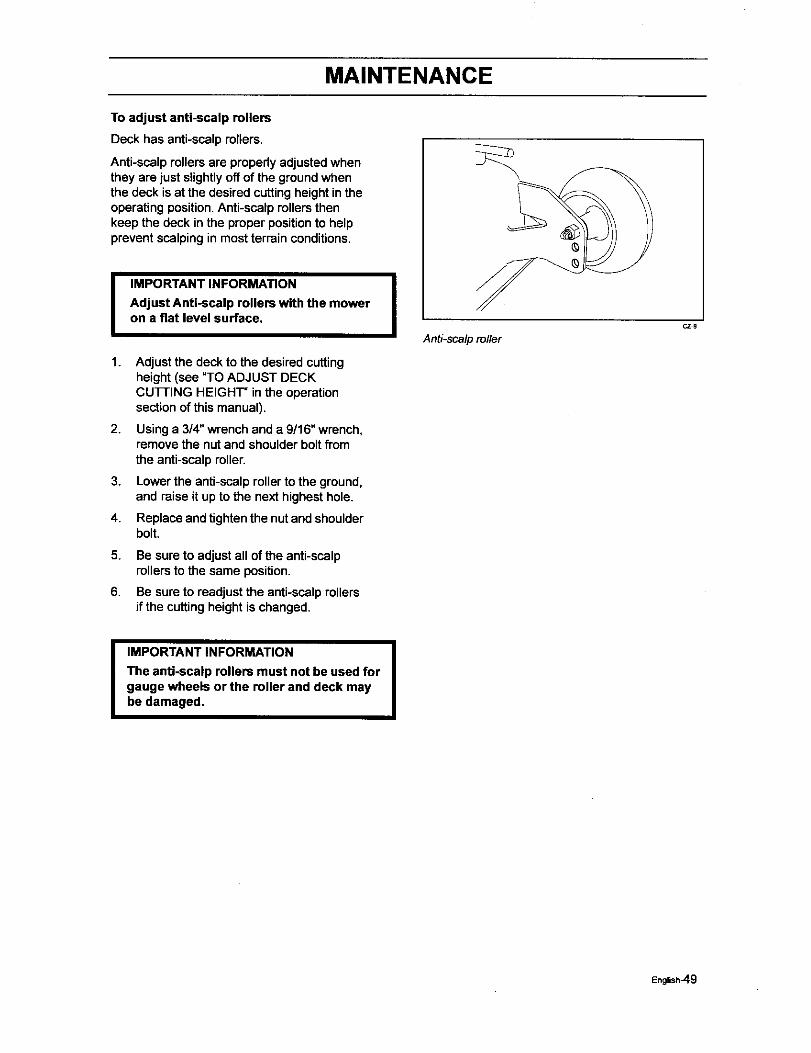
To adjust anti-scalp rollers
Deck has anti-scalpmilers.
Anti-scalp rollers are properlyadjustedwhenthey are just slightlyoff of the groundwhenthe deck is at the desired cuttingheight intheoperating position.Anti-scalp rollersthenkeep the deck inthe proper positionto helpprevent scalping in most terrainconditions.
I1.
2.
3.
4.
5.
6.
IMPORTANT INFORMATION IAdjust Anti-scalp rollers with the moweron a flat level surface,
Adjust the deck to the desired cuttingheight (see "TO ADJUST DECKCUTTING HEIGHT" in the operationsection of this manual).
Using a 314"wrench and a 9/16" wrench,remove the nut and shoulderbolt fromthe anti-scalp roller.
Lower the anti-scalproller to the ground,and raise it up to the next highest hole.
Replace and tighten the nut and shoulderbolt.
Be sureto adjust all of the anti-scalpmilers to the same position.
Be sureto readjust the anti-scalprollersif the cuttingheight is changed.
Anti-sca/p ro/lerCZg
I IMPORTANT INFORMATION I
The anti-scalp rollers must not be used forgauge wheels or the roller and deck maybe damaged,
English_9
MAINTENANCE
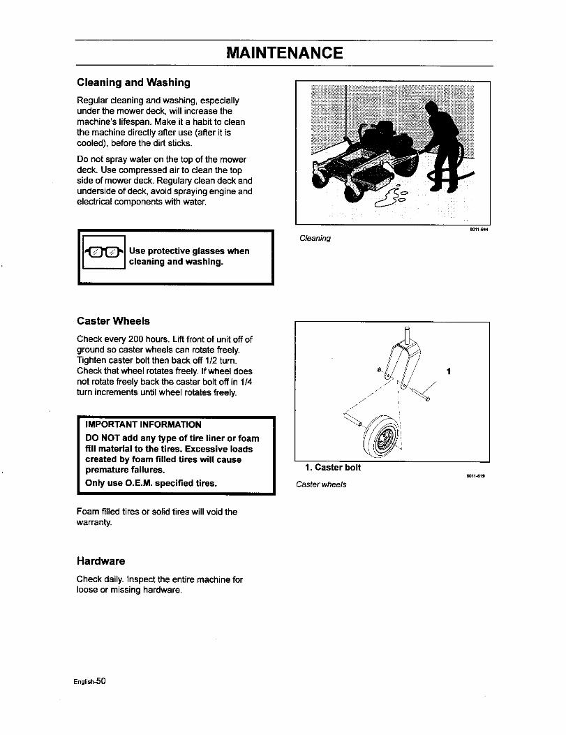
Cleaning and Washing
Regular cleaning and washing, especiallyunder the mower deck, will increase themachine's lifespan. Make it a habit to cleanthe machine directly after use (after it iscooled), before the dirt sticks.
Do not spraywater on the top of the mowerdeck. Use compressed air to clean the topside of mower deck. Regulary clean deck andunderside of deck, avoid spraying engine andelectrical components with water.
Use protective glasses whencleaning and washing. I Cleaning
_011J_44
Caster Wheels
Check every 200 hours. Lift front of unit off ofgroundso caster wheels can rotate freely."nghten caster bolt then back off 1/2 turn.Check that wheel rotates freely. If wheel doesnot rotate freely back the caster bolt off in 1/4turn increments until wheel rotates freely.
IMPORTANT INFORMATION
DO NOT add any type of tire liner or foamfill material to the tires. Excessive loadscreated by foam filled tires will causepremature failures.
Only use O.E.M. specified tires.
1/
/ / i
i
1. Caster bolt80H-619
Caster wheels
Foam filled tires or solid tires will void thewarranty.
Hardware
Check daily. Inspect the entire machine forloose or missinghardware,
English-5O
LUBRICATION
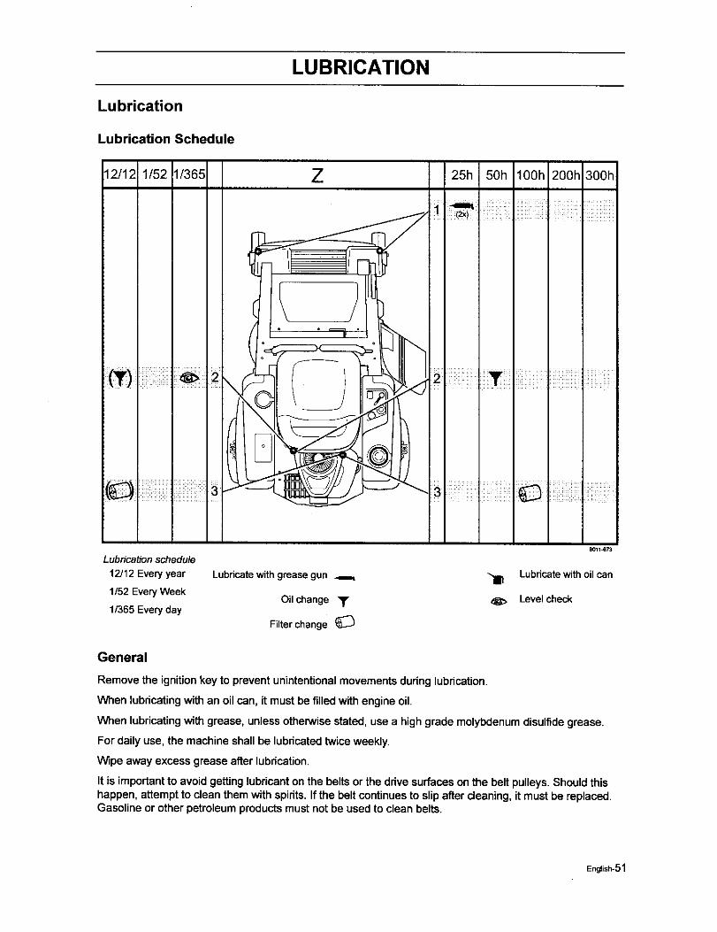
Lubrication
Lubrication Schedule
12/12 1/52 1/365 Z 25h 50h lOOh 200h 300h
I I I
\
8011_73
Lubricationschedule
12J12Everyyear Lubricatewith greasegun _ "_ Lubricatewith oil can1/52 EveryWeek
Oil change • d_, Level check1/365 Everyday
Filterchange
General
Remove the ignitionkey to prevent unintentional movements during lubrication.
When lubricating with an oil can, it must be filledwith engine oil.
When lubdcating with grease, unless otherwise stated, use a high grade molybdenum disulfide grease.
For daily use, the machine shall be lubricated twice weekly.
Wipe away excess grease after lubrication.
It is importantto avoid getting lubricanton the belts or the drive surfaces on the belt pulleys. Shouldthishappen, attempt to clean them with spirits.If the beltcontinuesto slip after cleaning, it must be replaced.Gasoline or other petroleum productsmust not be used to clean belts.
English-51
LUBRICATION
Lubricating the Cables
If possible, grease both ends of the cables and move the controls to end stop positions when lubricating.Refit the rubber covers on the cables after lubrication.Cables with sheathswill bindif they are notlubricatedregularty.If a ceble binds, it can disruptoperation.
If a cable binds, remove the cable and hang it vertically.Lubricateit with light engine oil until the oil beginsto escape fromthe bottom.
_p: Filla small plastic bag with oiland tape it so that it seals againstthe sheath and allow the cable to hangverticallyfrom the bag overnight. If you do notsucceed in lubricatingthe cable, it must be replaced.
Lubricating in Accordance with theLubrication Schedule
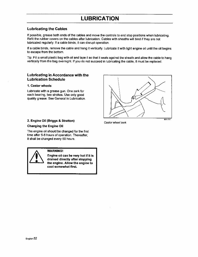
1. Caster wheels
Lubricate witha grease gun. One zerk foreach bearing,two strokes. Use only goodqualitygrease. See General in Lubrication.
2. Engine Oil (Briggs & Stratton)
Changing the Engine Oil
The engine oil should be changedfor the firsttime after 5-8 hoursof operation, Thereafter,it shall be changed every 50 hours,
Castor wheel zerk8011-717
WARNING!
Engine oil can be very hot if it isdrained directly after stoppingthe engine, Allow the engine tocool somewhat firaL
English-52
LUBRICATION
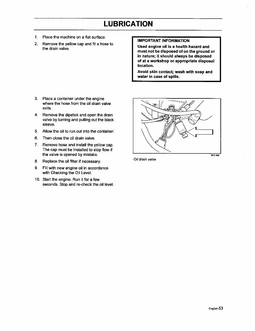
1. Place the machine on a flat surface.
2. Remove the yellow cap and fit a hose tothe drain valve.
IMPORTANT INFORMATION
Used engine oil is a health hazard andmust not be disposed of on the ground orin nature; it should always be disposedof at a workshop or appropriate disposallocation.
Avoid skin contact; wash with soap andwater in case of spills.
3. Place a container under the enginewhere the hose from the oil drain valveexits.
4. Remove the dipstick and open the drainvalve by turning and pulling out the blacksleeve.
5. Allow the oilto run out intothe container.
6. Then close the oil drain valve.
7,
8.
9.
Remove hose and install the yellow cap.The cap must be installedto stopflow ifthe valve is opened by mistake.
Replace the oil filter if necessary.
Fill with new engine oil in accordancewith Checking the Oil Level.
10. Start the engine. Run it for a fewseconds. Stop and re-check the oil level.
Oil drain valveB011499
English-53
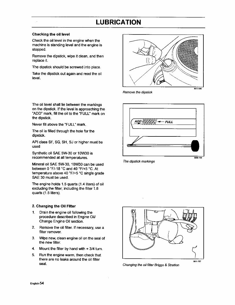
LUBRICATION
Checking the oil level
Check the oil level in the engine when the
machine is standing level and the engine isstopped.
Remove the dipstick, wipe it clean, and thenreplace it.
The dipstick should be screwed into place.
Take the dipstick out again and read the oillevel.
8011-900
Remove the dipstick
The oil level shall lie between the markingson the dipstick. If the level is approaching the"ADD" mark, fill the oil to the "FULL" mark onthe dipstick.
Never fill above the "FULL" mark.
The oil is filled through the hole for thedipstick.
API class SF, SG, SH, SJ or higher must beused
Synthetic oil SAE 5W-30 or 10W30 isrecommended at all temperatures.
Mineral oil SAE 5W-30, 10W30 can be usedbetween 0 °F/-18 °C and 40 °F/+5 °C. Attemperature above 40 °F/+5 °C single gradeSAE 30 must be used.
The engine holds 1.5 quarts (1.4 liters) ofoilexcluding the filter; includingthe filter 1.6quarts (1.5 liters).
_/ _ FULL
7
The dipstick markings
II800_159
2. Changing the Oil Filter
1. Drain the engineoil followingtheprocedure described in Engine Oil/Change Engine Oil section.
2. Remove the oil filter. If necessary, use afilter remover.
3. Wipe new, clean engine oil on the seal ofthe new filter.
4. Mount the filter by hand with + 3/4 turn.
5. Run the engine warm, then check thatthere are no leaks around the oil filterseal. Changing the oil filter Bdggs & Stratton
English-S4
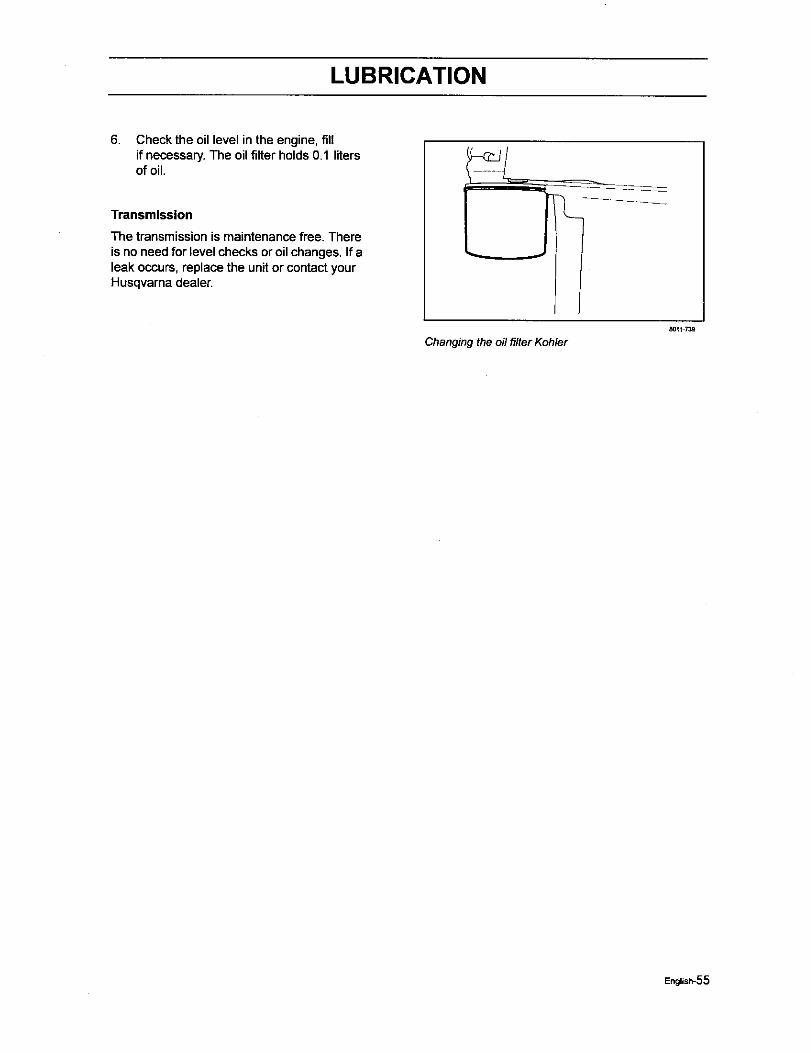
LUBRICATION
6. Check the oil level in the engine, fillif necessary.The oil filter holds0.1 litersof oil.
Transmission
The transmission is maintenance free. Thereis no need for level checks or oil changes. If aleak occurs, replace the unit or contact yourHusqvarna dealer.
Changing the oil filter Kohler80_1 739
English-55

TROUBLE SHOOTING GUIDE
Trouble Shooting Guide
Problem Cause
The engine will not start. The blade switch is engaged.
The steeringcontrolsare not locked intheneutral position.
The driver is not sittingin the driver'sseat.
The parking brake is not activated.
The battery is dead.
Contaminationinthe carburetoror fuel line.
The fuel supplyis closed orthe tapfor the fuel tanks is in the wrong position.
Clogged fuel filteror fuel line.
The starter motor does not turn the engine over. Dead battery.
Poor contacts onthe batteryterminalcable connections.
Fuse blown.
Ignitionsystem faulty.
Fault in the startermotor safety circuit.See Checking the Safety System inthe
Maintenance section.
The engine runs rough. Faulty carburetor.
The chokecontrol is pulled outwitha warm engine.
Defective valves.
Defective piston,cylinder, pistonring, orcylinderhead seal.
The cylinder head boltsare loose.
Clogged fuel filter or jet.
Clogged ventilationvalve on the fuel cap.
Fuel tank nearly empty.
Defective spark plug.
The spark plug is loose.
Defective ignitioncable.
Defective spark plugelectrode.
Defective spark plugconnection.
Rich fuel mixture or fuel-air mixture.
English-56

TROUBLE SHOOTING GUIDE
Wrong fuel type.
Water in the fuel.
Clogged air filter.
The engine seems weak. Clogged air filter.
Defective spark plug.
Carburetor incorrectlyadjusted.
The engine overheats. Clogged air intake or cooling fins.
Engine overloaded.
Poor ventilationaround engine.
Defective engine speed regulator.
Soot inthe combustionchamber.
Too little or no oil inthe engine.
Defective spark plug.
Pre-ignitionincorrect.
Battery notcharging. Poor contact with battery terminalcable connectors.
The machine moves slowly, unevenly,
or not at all.
Parking brake on.
Bypass valve on pump open.
Ddve belt for the transmissiongears slack orhas come off.
Mower deck not engaging. Drive belt for the mower deck has come loose.
Contact for the electromagneticcouplinghas loosened.
The blade switchis faultyor has come loose,from the cable contact.
The fuse has blown.
English-57

TROUBLE SHOOTING GUIDE
Uneven mowingresults. Differentair pressure in the tires on the left andright sides.
Bent blades.
The suspending for the mower deckis uneven.
The blades are blunt.
Driving speed too high.
The grass is too long.
Grass collected under the mower deck.
The machine vibrates. The blades are loose.
The blades are incorrectly balanced.
The engine is loose.
English-58
STORAGE
Storage
Winter Storage
At the end of the mowing season, the machineshould be readied for storage (or if it will not be inuse for longer than 30 days). Fuel allowed tostand for long periodsof time (30 days or more)can leave stickyresiduesthat can foul thecarburetor and disrupt engine function.
Fuel stabilizersare an acceptable option asregards to the stickyresiduesthat can occurduringstorage.
Add stabilizer to the fuel in the tank or in thestorage container.Always use the mixingratiosspecifiedby the manufacturer of the stabilizer.Run the engine for at least 10 minutes atteradding the stabilizer so that it reaches thecarburetor. Do not empty the fuel tank and thecarburetor if you have added stabilizer.
WARNING!
Never store an engine with fuelin the tank indoors or in poorlyventilated spaces where fuelvapor can come in contact withopen flames, sparks, or a pilotlight such as in a boiler, hotwater tank, clothes drier, etc.Handle the fuel with care. It isvery flammable and carelessuse can cause serious personalinjury and property damage.Drain the fuel into an approvedcontainer outdoors and faraway from open flame. Neveruse gasoline for cleaning. Usea degreaser and warm waterinstead.
To ready the machine for storage, follow thesesteps:
1. Thoroughlyclean the machine, especiallyunder the mower deck. Touch up damage tothe paintand spray a thin layer of oil ontheundersideof the mower deck to avoidcorrosion.
2. Inspectthe machine for worn or damagedparts and tighten any nutsorscrews that mayhave become loose.
3.
4.
Change the engine oil; disposeof properly.
Empty the fuel tanks or add a fuel stabilizer.Start the engineand allow it to run untilthecarburetor is drained of fuel or the stabilizerhas reached the carburetor.
5.
6.
7.
Remove the spark plug and pour about atablespoonof engine oil into the cylinder.Turn over the engine so that the oil is evenlydistributedand then refit the spark plug.
Lubricateall grease zerks, joints, and axles.
Remove the battery. Clean, charge, and storethe batteryin a cool place, but protect itfromdirect cold.
8. Store the machine in a clean, dry place andcover it for extra protection.
Service
When orderingspare parts, please specifythepurchase year, model, type, and sedal number.
Always use genuine Husqvama spare parts.
An annual check-up at an authorized serviceworkshop is a good way to ensure that yourmachine performs its best the following season.
English_59
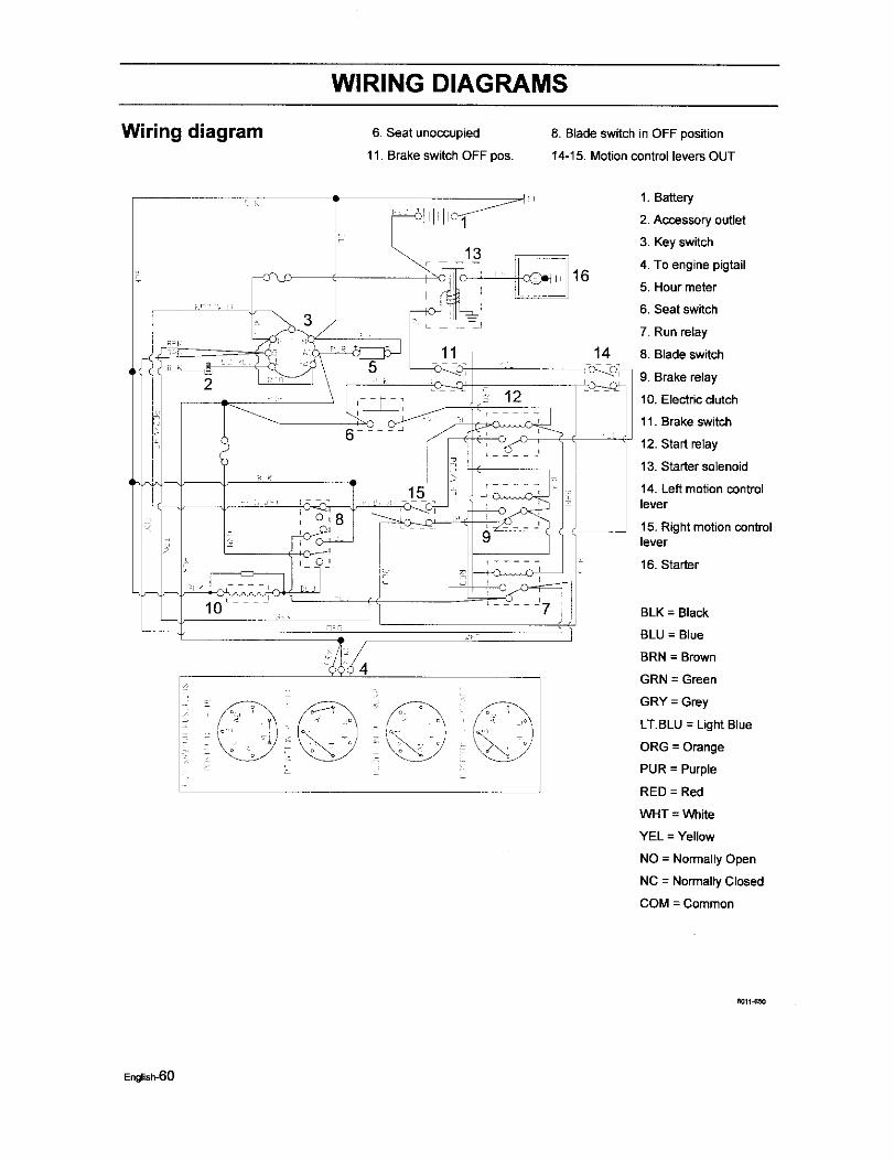
WIRING DIAGRAMS
Wiring diagram 6. Seat unoccupied
11. Brake switchOFF pos.
8. Blade switch in OFF position
14-15. Motioncontrol levers OUT
1. Battery
2. Accessory outlet
3. Key switch
4. To engine pigtail
5. Hour meter
6. Seat switch
2
147. Run relay
8. Blade switch
9. Brake relay
10. Electric clutch
11. Brake switch
12. Start relay
13. Starter solenoid
14. Left motion controllever
15. Right motion controllever
16. Starter
BLK = Black
BLU = Blue
BRN = Brown
GRN = Green
GRY = Grey
LT.BLU = Light Blue
ORG = Orange
PUR = Purple
RED = Red
WHT = White
YEL = Yellow
NO = NormallyOpen
NC = Normally Closed
COM = Common
8011_50
English-60
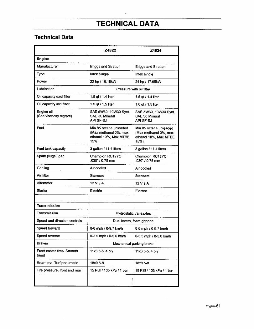
TECHNICAL DATA
Technical Data
Z4822 Z4824
Engine
Manufacturer Briggsand Straiten Briggsand Stratton
Type thtek Single Intek single
Power 22 hp / 16.18kW 24 hp / 17.65kW
Lubrication Pressure with oilfilter
Oil capacity excl filter 1.5 qt / 1.4 liter 1.5 qt / 1.4 liter
Oil capacity incl filter 1.6 qt / 1.5 liter 1.6 qt / 1.5 liter
Engine oil SAE 5W30, 10W30 Synt. SAE 5W30, 10W30 Synt.(See viscocitydigram) SAE 30 Mineral SAE 30 Mineral
API SF-SJ API SF-SJ
Fuel Min 85 octane unleaded Min 85 octane unleaded
(Max methanol 0%, max (Max methanol 0%, maxethanol 10%, Max MTBE ethanol 10%, Max MTBE15%) 15%)
Fuel tank capacity 3 gallon / 11.4 liters 3 gallon / 11.4 liters
Spark plugs/ gap Champion RC 12YC Champion RC12YC.030" / 0.75 mm .030" / 0.75 mm
Cooling Air cooled Air cooled
Air filter Standard Standard
Alternator 12 V 9 A 12 V 9 A
Starter Electric Electnc
Transmission
Transmission Hydrostatic transaxles
Speed and direction controls Dual levers, foam gripped
Speed forward 0-6 mph / 0-g.7 km/h 0-6 mph / 0-9.7 km/h
Speed reverse 0-3.5 mph / 0-5.6 km/h 0-3.5 mph / 0-5.6 km/h
Brakes Mechanical parkingbrake
Front caster tires, Smooth 11x3.5-5, 4 ply 11x3.5-5, 4 plytread
Rear tires, Turf pneumatic 18x9.5-6 18x9.5-6
Tire pressure, fi'ont and rear 15 PSi / 103 kPa / 1 bar 15 PSI / 103 kPa / 1 bar
English-61
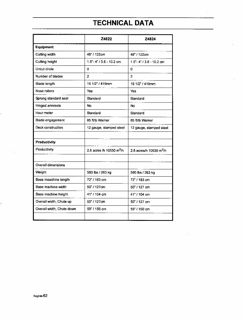
TECHNICAL DATA
Equipment
Cutting width
Cutting height
Uncut circle
Number of blades
Blade length
Nose rollers
Sprung standard seat
Hinged armrests
Hour meter
Blade engagement
Deck construction
Productivity
Productivity
Overall dimensions
Weight
Base maschine length
Base machine width
Base machine height
Overall width, Chute up
Overall width, Chute down
Z4822
48" / 122cm
1.5"-4 _/3.8 - 10.2 cm
0
2
16 1/2" / 419mm
Yes
Standard
No
Standard
85 ft/Ib Warner
12 gauge, stamped steel
2.6 acres/h 10530 m2/h
580 Ibs / 263 kg
72" / 183 cm
50" / 127cm
41"/104 cm
50" / 127cm
59" / 150 cm
Z4824
48" / 122cm
1.5"- 4" / 3.8 - 10.2 cm
0
2
16 1/2" / 419mm
Yes
Standard
No
Standard
85 ff/Ib Warner
12 gauge, stamped steel
2.6 acres/h 10530 m2/h
580 Ibs / 263 kg
72" / 183 crn
50" / 127 cm
41"/104 cm
50" / 127 crn
59"/150 cm
English-62
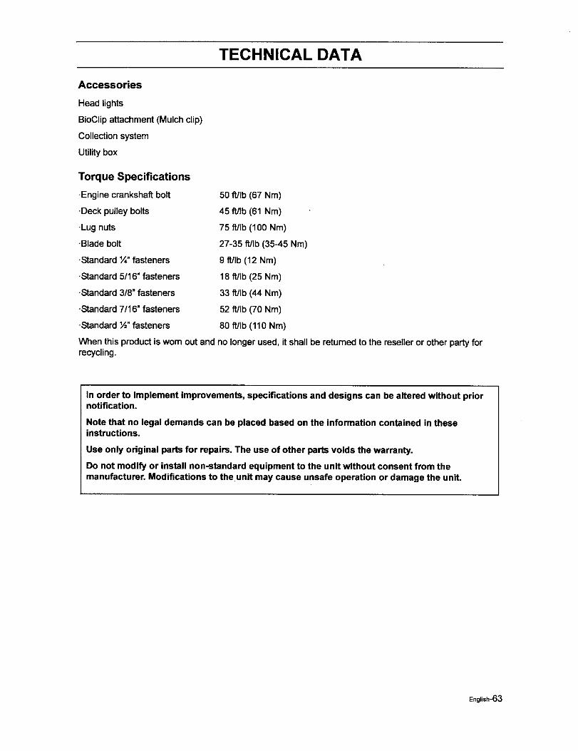
TECHNICAL DATA
Accessories
Head lights
BioClipattachment (Mulch clip)
Collection system
Utility box
Torque Specifications
-Engine crankshaftbolt
•Deck pulleybolts
-Lug nuts
•Blade bolt
•Standard t/4"fasteners
•Standard 5/16" fasteners
•Standard 3/8" fasteners
-Standard7/16" fasteners
-Standard½" fasteners
50 ft/Ib (67 Nm)
45 fl/Ib (61 Nm)
75 ft/Ib (100 Nm)
27-35 ft/Ib (35-45 Nm)
9 fdlb (12 Nm)
18 ft/Ib (25 Nm)
33 fdlb (44 Nm)
52 fdlb (70 Nm)
80 fdlb (110 Nm)
When this productis worn out and no longer used, it shall be returned to the reseller or other party forrecycling.
In order to implement improvements, specifications and designs can be altered without priornotification.
Note that no legal demands can be placed based on the information contained in theseinstructions.
Use only original parts for repairs. The use of other parts voids the warranty.
Do not modify or install non-standard equipment to the unit without consent from themanufacturer. Modifications to the unit may cause unsafe operation or damage the unit.
English-63

CONFORMITY CERTIFICATES
Conformity Certificates
USA requirements
Labels are placed on the engine and/or in the engine compartment statingthat the machine will fulfill therequirements. This is also applicable to special requirements for any of the states, (Californian emissionrules etc.). Do not remove any of these labels. Certificates can also be supplied with the machine atdelivery or written in the Engine manual. Take care of them as valuable documents.
English-64
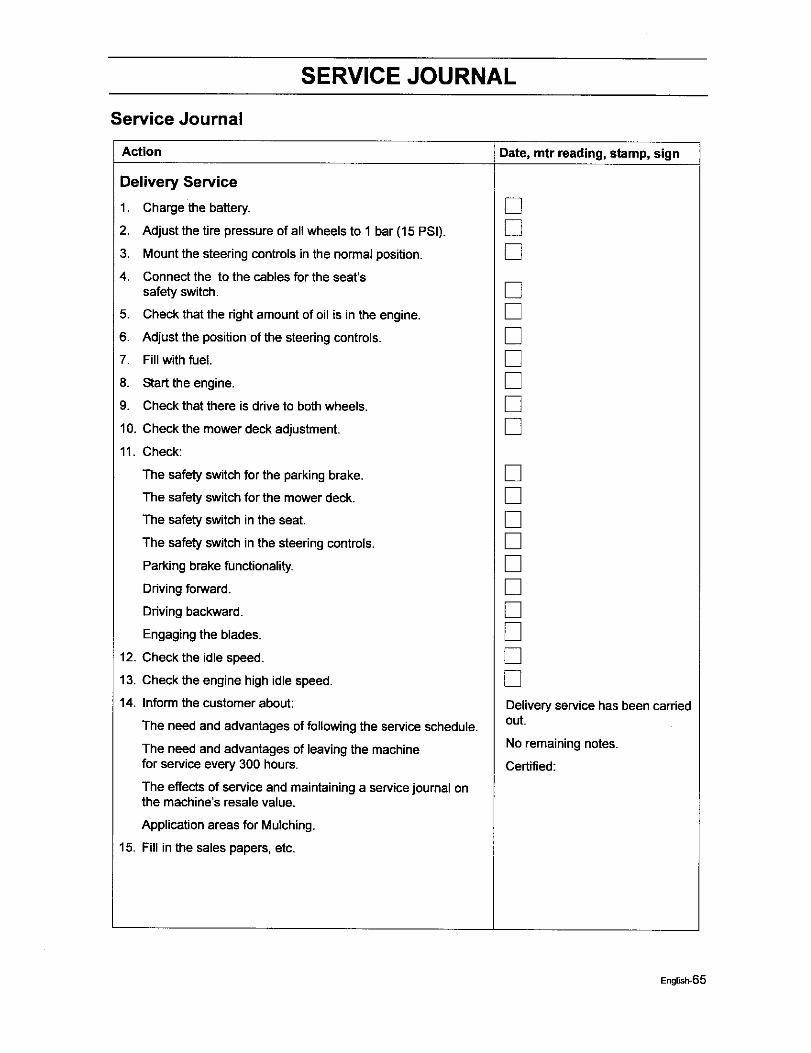
SERVICE JOURNAL
Service Journal
Action Date, mtr reading, stamp, sign
Delivery Service
1. Charge the battery.
2. Adjustthe tire pressure of all wheels to 1 bar (15 PSi).
3. Mountthe steeringcontrolsin the normal position.
4. Connectthe to the cables forthe seat'ssafety switch.
5. Check that the rightamount of oil is in the engine.
6. Adjustthe positionof the steeringcontrols.
7. Fillwith fuel
8. Start the engine.
9. Check that there is drive to bothwheels.
10. Check the mower deck adjustment.
11. Check:
The safety switchfor the parkingbrake.
The safety switchfor the mower deck.
The safetyswitch in the seat.
The safety switchin the steeringcontrols.
Parkingbrake functionality.
Ddvingforward.
Driving backward.
Engaging the blades.
12. Check the idle speed.
13. Check the engine high idle speed.
14. Inform the customer about:
The need and advantages of followingthe service schedule.
The need and advantages of leaving the machinefor service every 300 hours.
The effectsof service and maintaininga servicejournal onthe machine's resale value.
Applicationareas for Mulching.
15. Fill in the sales papers, etc.
[][][]
[][][][][][][]
[][][][][][][][][][]Deliveryservice has been cardedout.
No remaining notes.
Certified:
English-65
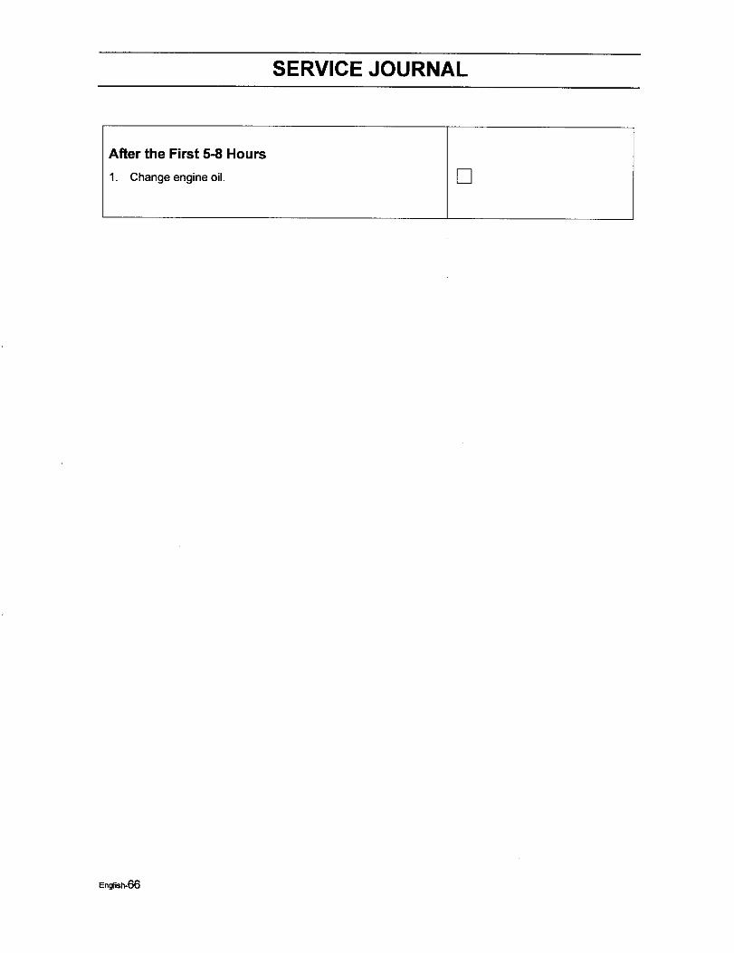
SERVICE JOURNAL
After the First 5-8 Hours
1. Change engine oil. []
English-66
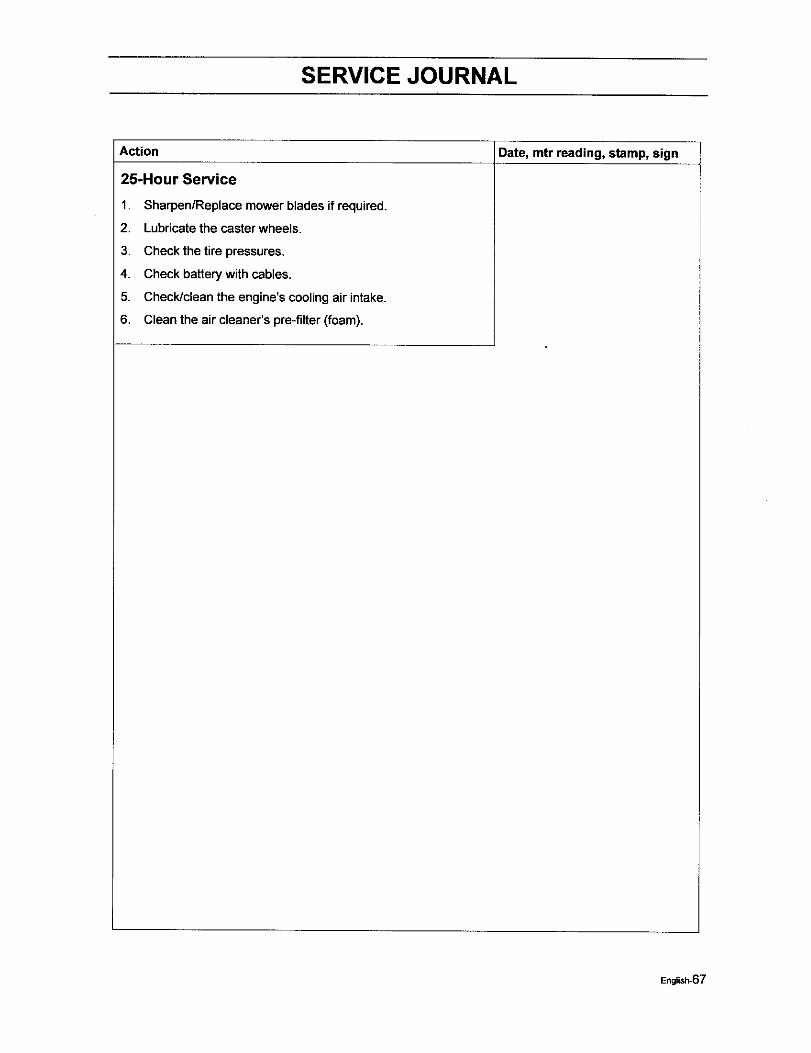
SERVICE JOURNAL
Date, mtr reading, stamp, signAction
25-Hour Service
1.
2.
3.
4.
5.
6.
Sharpen/Replaca mower blades if required.
Lubricate the caster wheels.
Check the tire pressures.
Check batterywith cables.
Check/clean the engine's coolingair intake.
Clean the air cleaner's pre-filter (foam).
English-67
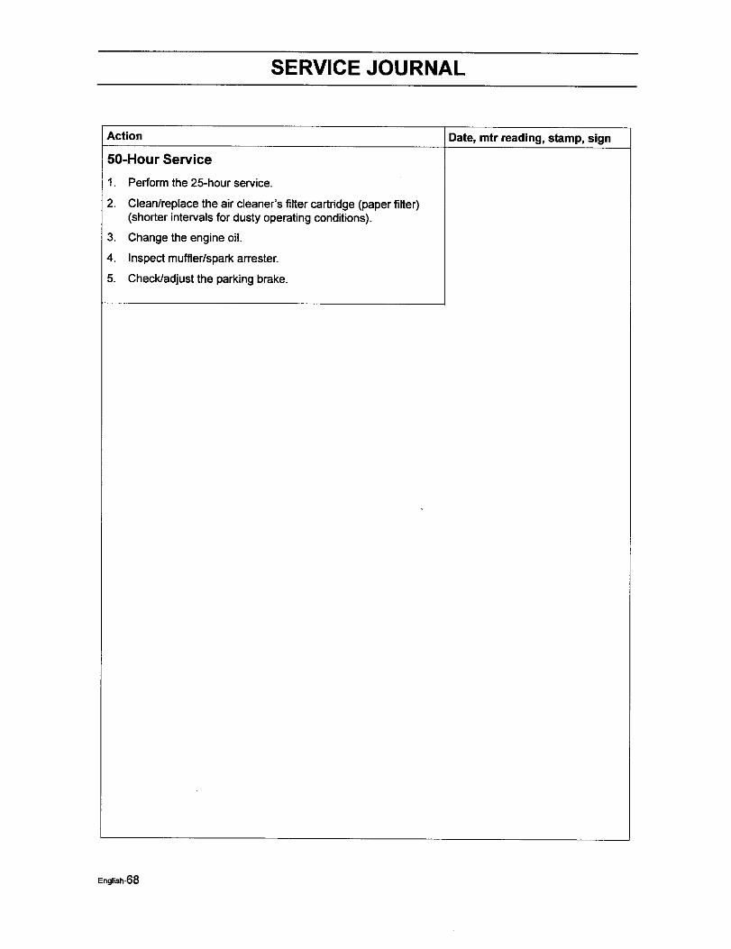
SERVICE JOURNAL
I Date, mtr reading, stamp, signAction
50-Hour Service
1.
2.
3.
4.
5.
Perform the 25-hour service.
Clean/replace the air cleaner's filter cartridge (paper filter)(shorter intervals for dusty operatingconditions).
Change the engine oil.
Inspect muffler/sparkarrester.
Check/adjustthe parkingbrake.
English-68
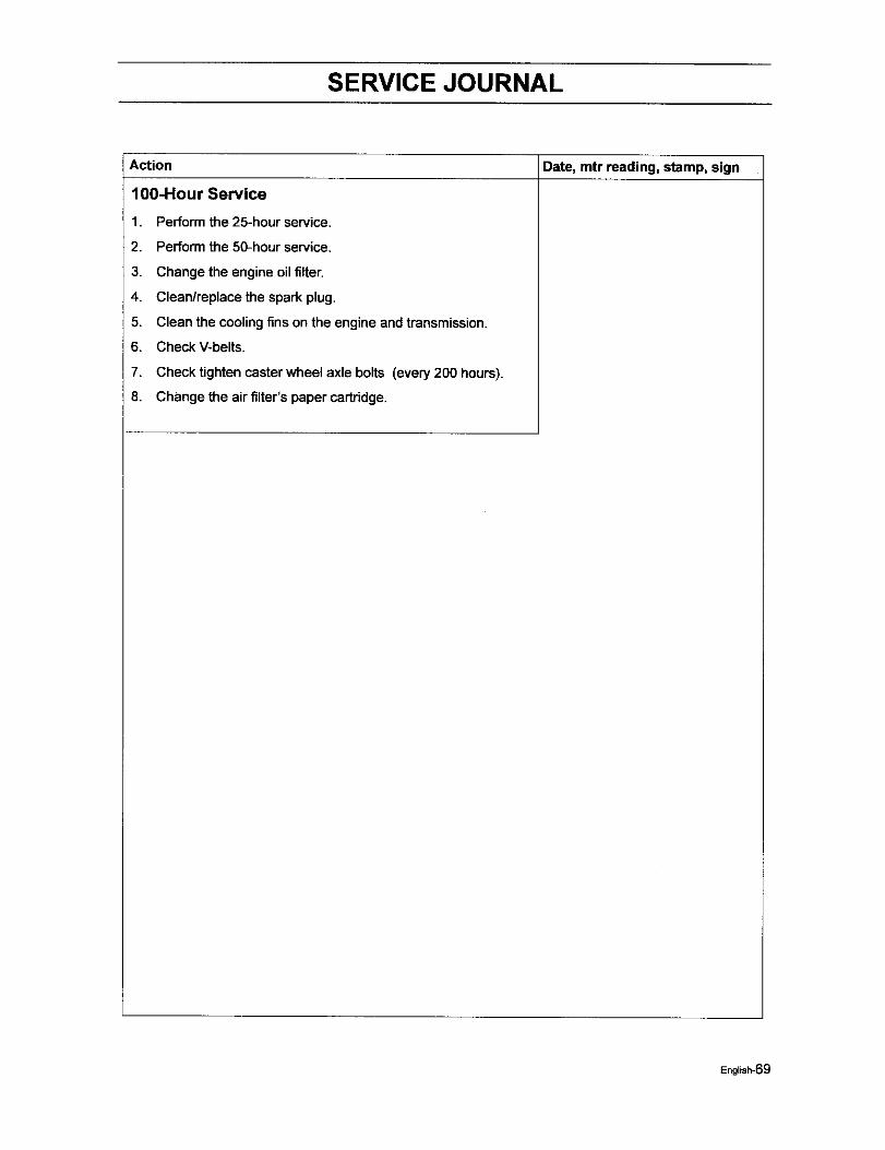
SERVICE JOURNAL
Date, mtr reading, stamp, signAction
100-Hour Service
1.
2.
3.
4.
5.
6,
7.
8.
Perform the 25-hour service.
Perform the 50-hour service.
Change the engine oil filter.
Clean/replace the spark plug.
Clean the cooling fins on the engine and transmission.
Check V-belts.
Check tighten caster wheel axle bolts (every 200 hours).
Change the air filter's paper cartridge.
English-69
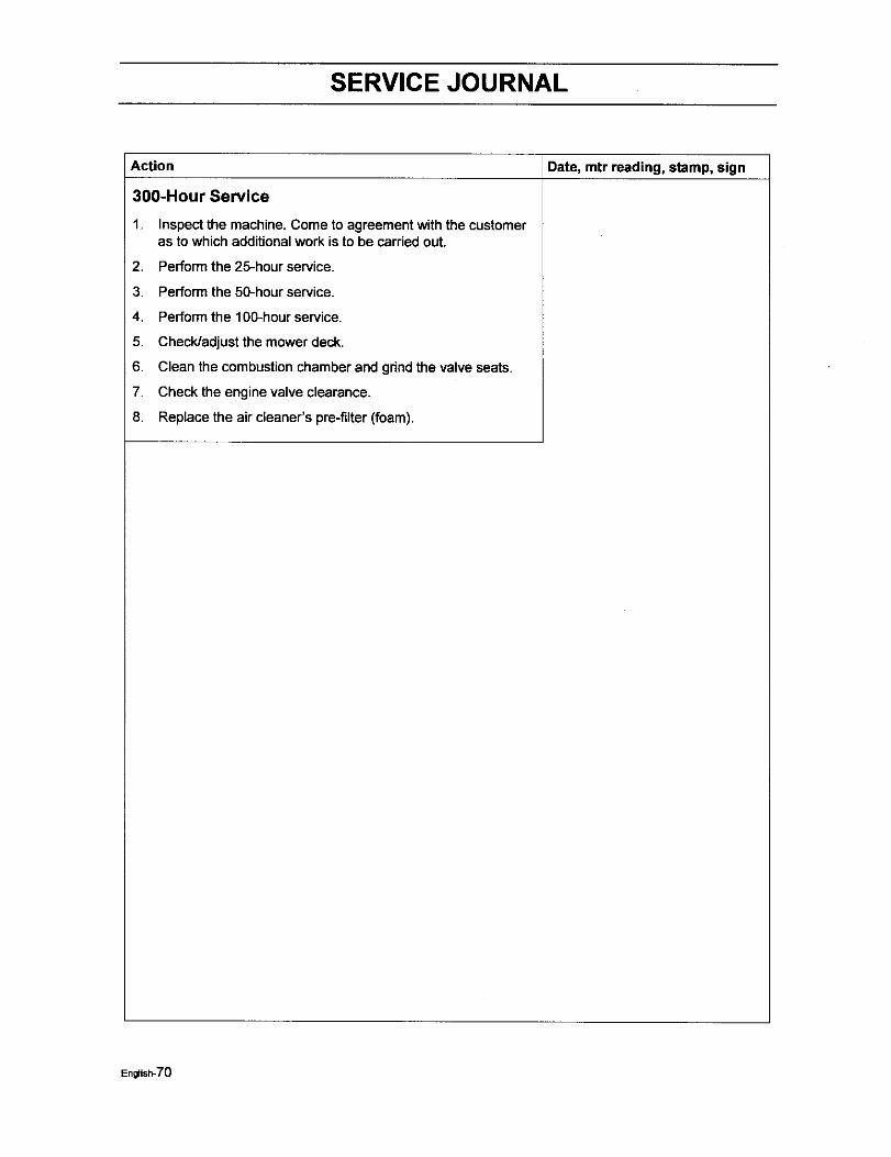
SERVICE JOURNAL
Date, mtr reading, stamp, signAction
300-Hour Service
1. Inspectthe machine, Come to agreement with the customeras to which additionalwork is to be carried out.
2. Perform the 25-hour service.
3. Perform the 50-hourservice.
4. Performthe 100-hourservice.
5. Check/adjust the mower deck.
6. Clean the combustionchamber and grindthe valve seats.
7. Check the engine valve clearance.
8. Replace the air cleaner's pra-filter (foam).
English-70
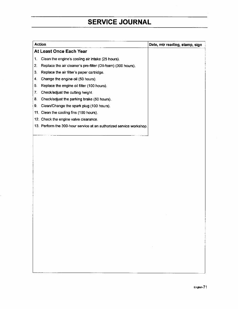
SERVICE JOURNAL
Action Date, mtr reading, stamp, sign
At Least Once Each Year
1. Clean the engine's cooling air intake (25 hours).
2. Replace the air cleaner's pre-filter (Oil-foam) (300 hours).
3. Replace the air filter's paper cartridge.
4. Change the engine oil (50 hours).
5. Replace the engine oil filter (100 hours),
7. Check/adjust the cutting height.
8. Check/adjust the parking brake (50 hours).
9. Clean/Change the spark plug (100 hours).
11. Clean the cooling fins (100 hours).
12. Check the engine valve clearance.
13. Perform the 300-hour serviceat an authorized serviceworkshop.
English-71

112690Rir 11/08/05