operation manual...operation manual part no’s: wg1-4b-1, wg1-4b-2, wg1-4b-4, wg1-4b-8 whirligig...
TRANSCRIPT

www.go4b.com/usa
Whirligig®UNIVERSAL SHAFT SENSOR MOUNT WITH FULLY GUARDED TARGET
INSTALLATION INSTRUCTIONS
OPERATION MANUALPart No’s: WG1-4B-1, WG1-4B-2, WG1-4B-4, WG1-4B-8
Whirligig Shown with M300 Slipswitch(All Sensors Sold Separately)
U.S. Patent #6,109,120

CUSTOMER SAFETY RESPONSIBILITIES Page 4 - 5
PRODUCT OVERVIEW Page 6
SPECIFICATIONS Page 6
DIMENSIONS Page 7
INSTALLATION INSTRUCTIONS Page 8
TROUBLESHOOTING GUIDE Page 9
PART NUMBERS & ACCESSORIES Page 9
COMPATIBLE SENSORS Page 10
PRODUCT WARRANTY Page 11
TABLE OF CONTENTS
Rotating parts can crush, cut and entangle.Do NOT operate with guard removed.Lockout power before removing guard or servicing.
WARNING
Whirligig® and Mag-Con™ are trademarks 4B Components Ltd., a subsidiary of T.F. & J.H. BRAIME (HOLDINGS) P.L.C.

PAGE 4
4B appreciates your business and is pleased you have chosen our products to meet your needs.
Please read in its entirety and understand the literature accompanying the product before you place the product into service. Please read the safety precautions carefully before operating the product. With each product you purchase from 4B, there are some basic but important safety considerations you must follow to be sure your purchase is permitted to perform its design function and operate properly and safely, giving you many years of reliable service. Please read and understand the Customer Safety Responsibilities listed below. Failure to follow this safety directive and the Operation Manuals and other material furnished or referenced, may result in serious injury or death.
SAFETY NOTICE TO OUR CUSTOMERS
A. In order to maximize efficiency and safety, selecting the right equipment for each operation is vital. The proper installation of the equipment, and regular maintenance and inspection is equally important in continuing the proper operation and safety of the product. The proper installation and maintenance of all our products is the responsibility of the user unless you have asked 4B to perform these tasks.
B. All installation and wiring must be in accordance with Local and National Electrical Codes and other standards applicable to your industry. (Please see the article “Hazard Monitoring Equipment Selection, Installation and Maintenance” at www.go4b.com.) The installation of the wiring should be undertaken by an experienced and qualified professional electrician. Failure to correctly wire any product and/or machinery can result in the product or machine failing to operate as intended, and can defeat its design function.
C. Periodic inspection by a qualified person will help assure your 4B product is performing properly. 4B recommends a documented inspection at least annually and more frequently under high use conditions.
D. Please see the last page of this manual for all warranty information regarding this product.
CUSTOMER SAFETY RESPONSIBILITIES
1. READ ALL LITERATURE PROVIDED WITH YOUR PRODUCT
Please read all user, instruction and safety manuals to ensure that you understand your product operation and are able to safely and effectively use this product. If the equipment is used in a manner not specified in this manual, the protection provided by the equipment may be impaired.
2. YOU BEST UNDERSTAND YOUR NEEDS
Every customer and operation is unique, and only you best know the specific needs and capabilities of your operation. Please call the 24-hour hotline at 309-698-5611 for assistance with any questions about the performance of products purchased from 4B. 4B is happy to discuss product performance with you at any time.
CUSTOMER SAFETY RESPONSIBILITIES

PAGE 5
3. SELECT A QUALIFIED AND COMPETENT INSTALLER
Correct installation of the product is important for safety and performance. If you have not asked 4B to perform the installation of the unit on your behalf, it is critical for the safety of your operation and those who may perform work on your operation that you select a qualified and competent electrical installer to undertake the installation. The product must be installed properly to perform its designed functions. The installer should be qualified, trained, and competent to perform the installation in accordance with Local and National Electrical Codes, all relevant OSHA Regulations, as well as any of your own standards and preventive maintenance requirements, and other product installation information supplied with the product. You should be prepared to provide the installer with all necessary installation information to assist in the installation.
4. ESTABLISH AND FOLLOW A REGULAR MAINTENANCE AND INSPECTION SCHEDULE FOR YOUR 4B PRODUCTS
You should develop a proper maintenance and inspection program to confirm that your system is in good working order at all times. You will be in the best position to determine the appropriate frequency for inspection. Many different factors known to the user will assist you in deciding the frequency of inspection. These factors may include but are not limited to weather conditions; construction work at the facility; hours of operation; animal or insect infestation; and the real-world experience of knowing how your employees perform their jobs. The personnel or person you select to install, operate, maintain, inspect or perform any work whatsoever, should be trained and qualified to perform these important functions. Complete and accurate records of the maintenance and inspection process should be created and retained by you at all times.
5. RETAIN AND REFER TO THE OPERATION MANUAL FOR 4B’S SUGGESTED MAINTENANCE AND INSPECTION RECOMMENDATIONS
As all operations are different, please understand that your specific operation may require additional adjustments in the maintenance and inspection process essential to permit the monitoring device to perform its intended function. Retain the Operation Manual and other important maintenance and service documents provided by 4B and have them readily available for people servicing your 4B equipment. Should you have any questions, please call the free 24-hour hotline number (309-698-5611).
6. SERVICE REQUEST
If you have questions or comments about the operation of your unit or require the unit to be serviced please contact the 4B location who supplied the product or send your request via fax (309-698-5615) or call us via our 24-hour hotline number in the USA (309-698-5611). Please have available product part numbers, serial numbers, and approximate date of installation. In order to assist you, after the product has been placed into service, complete the online product registration section which is accessed via our website www.go4b.com/usa.
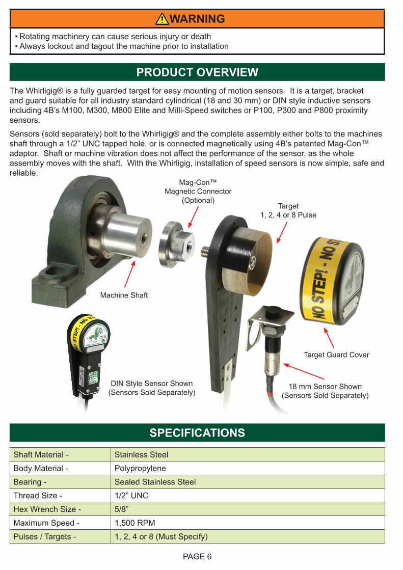
PRODUCT OVERVIEWThe Whirligig® is a fully guarded target for easy mounting of motion sensors. It is a target, bracket and guard suitable for all industry standard cylindrical (18 and 30 mm) or DIN style inductive sensors including 4B’s M100, M300, M800 Elite and Milli-Speed switches or P100, P300 and P800 proximity sensors.
Sensors (sold separately) bolt to the Whirligig® and the complete assembly either bolts to the machines shaft through a 1/2” UNC tapped hole, or is connected magnetically using 4B’s patented Mag-Con™ adaptor. Shaft or machine vibration does not affect the performance of the sensor, as the whole assembly moves with the shaft. With the Whirligig, installation of speed sensors is now simple, safe and reliable.
SPECIFICATIONS
Shaft Material - Stainless Steel
Body Material - Polypropylene
Bearing - Sealed Stainless Steel
Thread Size - 1/2” UNC
Hex Wrench Size - 5/8”
Maximum Speed - 1,500 RPM
Pulses / Targets - 1, 2, 4 or 8 (Must Specify)
WARNING• Rotating machinery can cause serious injury or death• Always lockout and tagout the machine prior to installation
PAGE 6
Machine Shaft
Target1, 2, 4 or 8 Pulse
18 mm Sensor Shown (Sensors Sold Separately)
Target Guard Cover
Mag-Con™Magnetic Connector
(Optional)
DIN Style Sensor Shown(Sensors Sold Separately)
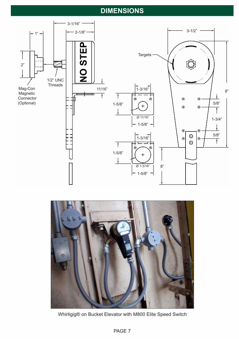
DIMENSIONS
PAGE 7
Mag-ConMagnetic
Connector(Optional)
2”
1” 2-1/8”
3-1/16”
11/16” 1-3/16”
1-5/8”
1-3/16”
1-5/8”
1-5/8”
1-5/8”
Ø 1-3/16”
Ø 11/16”
3-1/2”
5/8”
5/8”
8”
1-3/4”
8”
1/2” UNCThreads
Targets
Whirligig® on Bucket Elevator with M800 Elite Speed Switch
PAGE 8
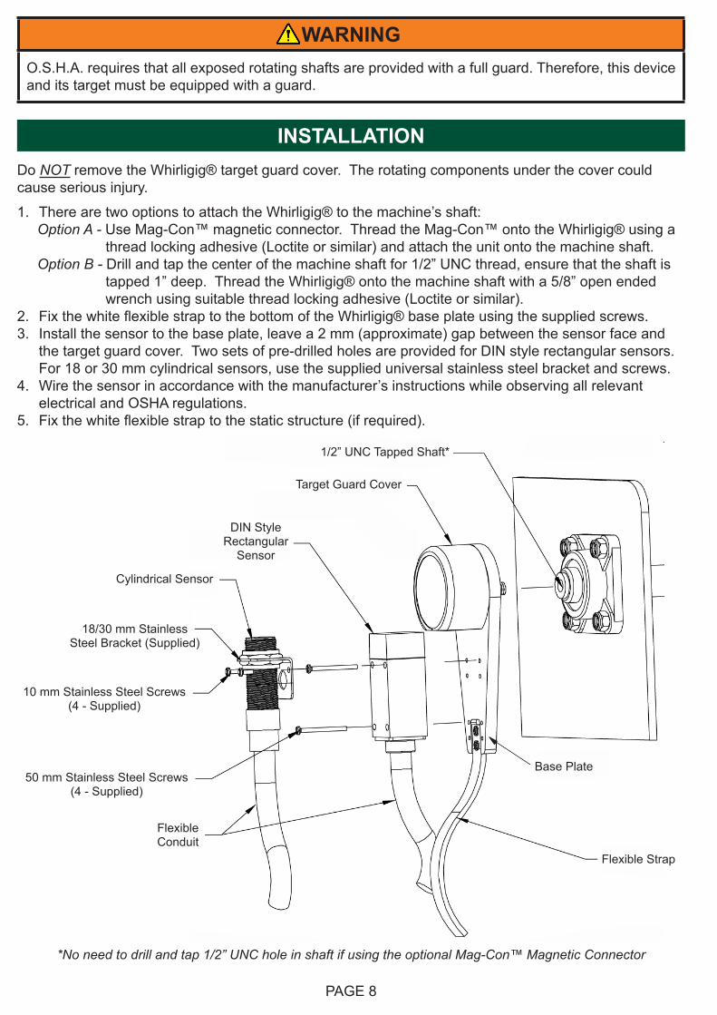
WARNINGO.S.H.A. requires that all exposed rotating shafts are provided with a full guard. Therefore, this device and its target must be equipped with a guard.
Flexible Conduit
Flexible Strap
50 mm Stainless Steel Screws(4 - Supplied)
18/30 mm StainlessSteel Bracket (Supplied)
10 mm Stainless Steel Screws(4 - Supplied)
Cylindrical Sensor
DIN StyleRectangular
Sensor
Target Guard Cover
1/2” UNC Tapped Shaft*
Base Plate
*No need to drill and tap 1/2” UNC hole in shaft if using the optional Mag-Con™ Magnetic Connector
INSTALLATIONDo NOT remove the Whirligig® target guard cover. The rotating components under the cover could cause serious injury.
1. There are two options to attach the Whirligig® to the machine’s shaft: Option A - Use Mag-Con™ magnetic connector. Thread the Mag-Con™ onto the Whirligig® using a thread locking adhesive (Loctite or similar) and attach the unit onto the machine shaft. Option B - Drill and tap the center of the machine shaft for 1/2” UNC thread, ensure that the shaft is tapped 1” deep. Thread the Whirligig® onto the machine shaft with a 5/8” open ended wrench using suitable thread locking adhesive (Loctite or similar).2. Fix the white flexible strap to the bottom of the Whirligig® base plate using the supplied screws.3. Install the sensor to the base plate, leave a 2 mm (approximate) gap between the sensor face and
the target guard cover. Two sets of pre-drilled holes are provided for DIN style rectangular sensors. For 18 or 30 mm cylindrical sensors, use the supplied universal stainless steel bracket and screws.
4. Wire the sensor in accordance with the manufacturer’s instructions while observing all relevant electrical and OSHA regulations.
5. Fix the white flexible strap to the static structure (if required).

PAGE 9
TROUBLESHOOTING GUIDE
FAULT REMEDY
Sensor does not Detect Whirligig® Target
1. Check the sensing range of the sensor being used, and move sensor closer to the target.
2. Check to make sure the sensor being used can detect a moving non-ferrous metal target. If not, try WG4-4B-4 with 400 series stainless steel target.
Whirligig® Unscrews from the Machine’s Shaft
Use thread locking adhesive (Loctite or similar) on the threads of the Whirligig®.
PART NUMBERS & ACCESSORIES
WG1-4B-1 Whirligig® with 1 Pulse / Target
WG1-4B-2 Whirligig® with 2 Pulse / Target
WG1-4B-4 Whirligig® with 4 Pulse / Target (Standard)
WG4-4B-4 Whirligig® with 4 Pulse / Target (Stainless Steel)
WG1-4B-8 Whirligig® with 8 Pulse / Target
WGB1830 18 / 30 mm Stainless Steel Bracket (Supplied)
MAG2000 Mag-Con™ Magnetic Connector (Optional)
Mag-Con™ Magnetic ConnectorThis optional accessory screws onto the Whirligig® and magnetically couples to the shaft being monitored, simplifying installation.
Material: Stainless SteelHolding Force: Over 100 lbs.Maximum Shaft Speed: 300 RPMTemperature Range: -40°F to 194°F (-40°C to 90°C)
U.S. Patent #6,964,209
Whirligig® Installed on the Tail Shaft of Enclosed Conveyor with M800 Elite Speed Switch

PAGE 10
4B COMPATIBLE SENSORS
M8001V10C M800 Elite Speed Switch
MIL8001V4C Milli-Speed Switch (4-20 mA)
M3001V10F M300 Slipswitch (2 Wire)
M3005V10CA M300 Slipswitch (5 Wire)
M1001V10F M100 Stopswitch
P8004V10C P800 ProxSwitch (Output Off)
P3002V10C P300 ProxSwitch
P3001V34C P300 ProxSwitch (NPN/PNP)
P1002V10C P100 ProxSwitch
P1001V34C P100 ProxSwitch (NPN/PNP)
KIT-SM2 SpeedMaster™ Speed Switch Calibration and Testing Device
For More Information on Whirligig® Accessories and Compatible Sensors, Visit www.go4b.com/usa
SpeedMaster™The SpeedMaster with Pulse Pilot is the only device that accurately tests the calibration of a speed switch, and allows testing of the alarm and shutdown features of the sensor while installed on the machine shaft.The SpeedMaster operates in two modes. Input mode is used to measure the pulse rate at normal speed. Output mode will allow the user to simulate underspeed for testing purposes.The Pulse Pilot fits in the gap between the sensor and the target. The Pulse Pilot will have no effect on the operation of the speed switch until it is connected to the SpeedMaster and set to “output” mode.
Speed Switch Sensors4B’s line of speed switches include: proximity, inductive, zero speed and stop motion to monitor dangerous belt slip, underspeed or stop conditions on conveyors, bucket elevators and any other rotating machinery.
Inductive Proximity Sensors4B’s line of inductive proximity sensors are designed to detect shaft speed, shaft position, gate position, or object presence.
Patents -US8947073MX321802EP26223568
PAGE 11
1. EXCLUSIVE WRITTEN LIMITED WARRANTY
ALL PRODUCTS SOLD ARE WARRANTED BY THE COMPANY 4B COMPONENTS LIMITED AND 4B BRAIME COMPONENTS LIMITED HEREIN AFTER REFERRED TO AS 4B TO THE ORIGINAL PURCHASER AGAINST DEFECTS IN WORKMANSHIP OR MATERIALS UNDER NORMAL USE FOR ONE (1) YEAR AFTER DATE OF PURCHASE FROM 4B. ANY PRODUCT DETERMINED BY 4B AT ITS SOLE DISCRETION TO BE DEFECTIVE IN MATERIAL OR WORKMANSHIP AND RETURNED TO A 4B BRANCH OR AUTHORIZED SERVICE LOCATION, AS 4B DESIGNATES, SHIPPING COSTS PREPAID, WILL BE, AS THE EXCLUSIVE REMEDY, REPAIRED OR REPLACED AT 4B’S OPTION.
2. DISCLAIMER OF IMPLIED WARRANTY
NO WARRANTY OR AFFIRMATION OF FACT, EXPRESSED OR IMPLIED, OTHER THAN AS SET FORTH IN THE EXCLUSIVE WRITTEN LIMITED WARRANTY STATEMENT ABOVE IS MADE OR AUTHORIZED BY 4B. 4B SPECIFICALLY DISCLAIMS ANY LIABILITY FOR PRODUCT DEFECT CLAIMS THAT ARE DUE TO PRODUCT MISUSE, ABUSE OR MISAPPLICATIONS, AS AUTHORIZED BY LAW, 4B SPECIFICALLY DISCLAIMS ALL WARRANTIES THAT THE PRODUCT IS FIT OR MERCHANTABLE FOR A PARTICULAR PURPOSE.
3. NO WARRANTY “BY SAMPLE OR EXAMPLE”
ALTHOUGH 4B HAS USED REASONABLE EFFORTS TO ACCURATELY ILLUSTRATE AND DESCRIBE THE PRODUCTS IN ITS CATALOGS, LITERATURE, AND WEBSITES, SUCH ILLUSTRATIONS AND DESCRIPTIONS ARE FOR THE SOLE PURPOSE OF PRODUCT IDENTIFICATION AND DO NOT EXPRESS OR IMPLY A WARRANTY AFFIRMATION OF FACT, OF ANY KIND OR A WARRANTY OR AFFIRMATION OF FACT THAT THE PRODUCTS WILL CONFORM TO THEIR RESPECTIVE ILLUSTRATIONS OR DESCRIPTIONS. 4B EXPRESSLY DISCLAIMS ANY WARRANTY OR AFFIRMATION OF FACT, EXPRESSED OR IMPLIED, OTHER THAN AS SET FORTH IN THE EXCLUSIVE WRITTEN LIMITED WARRANTY STATEMENT ABOVE, INCLUDING, WITHOUT LIMITATION, THE IMPLIED WARRANTIES OF MERCHANTABILITY AND FITNESS FOR A PARTICULAR PURPOSE.
4. LIMITATION OF DAMAGES
ANY LIABILITY FOR CONSEQUENTIAL, INCIDENTAL, SPECIAL, EXEMPLARY, OR PUNITIVE DAMAGES, OR FOR LOSS OF PROFIT WHETHER DIRECT OR INDIRECT, IS EXPRESSLY DISCLAIMED.
PRODUCT WARRANTY

Copyright © 2018 4B Group - All Rights Reserved
With subsidiaries in North America, Europe, Asia, Africa and Australia along with a worldwide network of distributors, 4B can provide practical solutions for all your applications no matter the location.
www.go4b.com REV70518
4B FRANCE9 Route de Corbie80800 Lamotte WarfuséeFranceTel: +33 (0) 3 22 42 32 26Fax: +33 (0) 3 22 42 37 33
4B AFRICA14 Newport Business Park Mica Drive, Kya Sand2163 JohannesburgSouth AfricaTel: +27 (0) 11 708 6114Fax: +27 (0) 11 708 1654
4B AUSTRALIABuilding 1, 41 Bellrick StreetAcacia Ridge, 4110QueenslandAustraliaTel: +61 (0) 7 3216 9365Fax: +61 (0) 7 3219 5837
4B COMPONENTS LTD.625 Erie AvenueMorton, IL 61550USATel: 309-698-5611Fax: 309-698-5615
4B BRAIME COMPONENTS LTD.Hunslet RoadLeeds LS10 1JZUnited KingdomTel: +44 (0) 113 246 1800Fax: +44 (0) 113 243 5021
4B DEUTSCHLAND9 Route de CorbieLamotte WarfuséeF-80800FranceTel: +49 (0) 700 2242 4091Fax: +49 (0) 700 2242 3733
4B ASIA PACIFICBuild No. 899/1 Moo 20Soi Chongsiri, Bangplee-Tam Ru Road, Tanbon Bangpleeyai, Amphur Bangplee,Samutprakarn 10540ThailandTel: +66 (0) 2 173-4339Fax: +66 (0) 2 173-4338